EP0849486A2 - Verfahren zum Wechsel der Bremsscheibe einer Scheibenbremse sowie zugehörige Scheibenbremse - Google Patents
Verfahren zum Wechsel der Bremsscheibe einer Scheibenbremse sowie zugehörige Scheibenbremse Download PDFInfo
- Publication number
- EP0849486A2 EP0849486A2 EP97121038A EP97121038A EP0849486A2 EP 0849486 A2 EP0849486 A2 EP 0849486A2 EP 97121038 A EP97121038 A EP 97121038A EP 97121038 A EP97121038 A EP 97121038A EP 0849486 A2 EP0849486 A2 EP 0849486A2
- Authority
- EP
- European Patent Office
- Prior art keywords
- brake
- disc
- brake disc
- wheel
- carrier
- Prior art date
- Legal status (The legal status is an assumption and is not a legal conclusion. Google has not performed a legal analysis and makes no representation as to the accuracy of the status listed.)
- Granted
Links
Images


Classifications
-
- B—PERFORMING OPERATIONS; TRANSPORTING
- B60—VEHICLES IN GENERAL
- B60B—VEHICLE WHEELS; CASTORS; AXLES FOR WHEELS OR CASTORS; INCREASING WHEEL ADHESION
- B60B27/00—Hubs
- B60B27/001—Hubs with roller-bearings
-
- B—PERFORMING OPERATIONS; TRANSPORTING
- B60—VEHICLES IN GENERAL
- B60T—VEHICLE BRAKE CONTROL SYSTEMS OR PARTS THEREOF; BRAKE CONTROL SYSTEMS OR PARTS THEREOF, IN GENERAL; ARRANGEMENT OF BRAKING ELEMENTS ON VEHICLES IN GENERAL; PORTABLE DEVICES FOR PREVENTING UNWANTED MOVEMENT OF VEHICLES; VEHICLE MODIFICATIONS TO FACILITATE COOLING OF BRAKES
- B60T1/00—Arrangements of braking elements, i.e. of those parts where braking effect occurs specially for vehicles
- B60T1/02—Arrangements of braking elements, i.e. of those parts where braking effect occurs specially for vehicles acting by retarding wheels
- B60T1/06—Arrangements of braking elements, i.e. of those parts where braking effect occurs specially for vehicles acting by retarding wheels acting otherwise than on tread, e.g. employing rim, drum, disc, or transmission or on double wheels
- B60T1/065—Arrangements of braking elements, i.e. of those parts where braking effect occurs specially for vehicles acting by retarding wheels acting otherwise than on tread, e.g. employing rim, drum, disc, or transmission or on double wheels employing disc
-
- F—MECHANICAL ENGINEERING; LIGHTING; HEATING; WEAPONS; BLASTING
- F16—ENGINEERING ELEMENTS AND UNITS; GENERAL MEASURES FOR PRODUCING AND MAINTAINING EFFECTIVE FUNCTIONING OF MACHINES OR INSTALLATIONS; THERMAL INSULATION IN GENERAL
- F16D—COUPLINGS FOR TRANSMITTING ROTATION; CLUTCHES; BRAKES
- F16D65/00—Parts or details
- F16D65/02—Braking members; Mounting thereof
- F16D65/12—Discs; Drums for disc brakes
- F16D65/123—Discs; Drums for disc brakes comprising an annular disc secured to a hub member; Discs characterised by means for mounting
-
- F—MECHANICAL ENGINEERING; LIGHTING; HEATING; WEAPONS; BLASTING
- F16—ENGINEERING ELEMENTS AND UNITS; GENERAL MEASURES FOR PRODUCING AND MAINTAINING EFFECTIVE FUNCTIONING OF MACHINES OR INSTALLATIONS; THERMAL INSULATION IN GENERAL
- F16D—COUPLINGS FOR TRANSMITTING ROTATION; CLUTCHES; BRAKES
- F16D55/00—Brakes with substantially-radial braking surfaces pressed together in axial direction, e.g. disc brakes
- F16D2055/0004—Parts or details of disc brakes
- F16D2055/0008—Brake supports
-
- F—MECHANICAL ENGINEERING; LIGHTING; HEATING; WEAPONS; BLASTING
- F16—ENGINEERING ELEMENTS AND UNITS; GENERAL MEASURES FOR PRODUCING AND MAINTAINING EFFECTIVE FUNCTIONING OF MACHINES OR INSTALLATIONS; THERMAL INSULATION IN GENERAL
- F16D—COUPLINGS FOR TRANSMITTING ROTATION; CLUTCHES; BRAKES
- F16D65/00—Parts or details
- F16D65/02—Braking members; Mounting thereof
- F16D2065/13—Parts or details of discs or drums
- F16D2065/1304—Structure
- F16D2065/1308—Structure one-part
-
- F—MECHANICAL ENGINEERING; LIGHTING; HEATING; WEAPONS; BLASTING
- F16—ENGINEERING ELEMENTS AND UNITS; GENERAL MEASURES FOR PRODUCING AND MAINTAINING EFFECTIVE FUNCTIONING OF MACHINES OR INSTALLATIONS; THERMAL INSULATION IN GENERAL
- F16D—COUPLINGS FOR TRANSMITTING ROTATION; CLUTCHES; BRAKES
- F16D65/00—Parts or details
- F16D65/02—Braking members; Mounting thereof
- F16D2065/13—Parts or details of discs or drums
- F16D2065/1304—Structure
- F16D2065/1328—Structure internal cavities, e.g. cooling channels
-
- F—MECHANICAL ENGINEERING; LIGHTING; HEATING; WEAPONS; BLASTING
- F16—ENGINEERING ELEMENTS AND UNITS; GENERAL MEASURES FOR PRODUCING AND MAINTAINING EFFECTIVE FUNCTIONING OF MACHINES OR INSTALLATIONS; THERMAL INSULATION IN GENERAL
- F16D—COUPLINGS FOR TRANSMITTING ROTATION; CLUTCHES; BRAKES
- F16D65/00—Parts or details
- F16D65/02—Braking members; Mounting thereof
- F16D2065/13—Parts or details of discs or drums
- F16D2065/134—Connection
- F16D2065/1356—Connection interlocking
- F16D2065/136—Connection interlocking with relative movement radially
-
- F—MECHANICAL ENGINEERING; LIGHTING; HEATING; WEAPONS; BLASTING
- F16—ENGINEERING ELEMENTS AND UNITS; GENERAL MEASURES FOR PRODUCING AND MAINTAINING EFFECTIVE FUNCTIONING OF MACHINES OR INSTALLATIONS; THERMAL INSULATION IN GENERAL
- F16D—COUPLINGS FOR TRANSMITTING ROTATION; CLUTCHES; BRAKES
- F16D69/00—Friction linings; Attachment thereof; Selection of coacting friction substances or surfaces
- F16D2069/004—Profiled friction surfaces, e.g. grooves, dimples
-
- F—MECHANICAL ENGINEERING; LIGHTING; HEATING; WEAPONS; BLASTING
- F16—ENGINEERING ELEMENTS AND UNITS; GENERAL MEASURES FOR PRODUCING AND MAINTAINING EFFECTIVE FUNCTIONING OF MACHINES OR INSTALLATIONS; THERMAL INSULATION IN GENERAL
- F16D—COUPLINGS FOR TRANSMITTING ROTATION; CLUTCHES; BRAKES
- F16D2250/00—Manufacturing; Assembly
- F16D2250/0084—Assembly or disassembly
Definitions
- the invention relates to a method for changing the brake disc Disc brake, in particular of commercial vehicles, the brake disc of which a friction ring and a brake disc hub over which the Brake disc on a wheel hub rotatably mounted on a steering knuckle is attached, the wheel flange for releasable attachment of a wheel has, the brake disc in the region of its friction ring with two Brake pads interacts with their brake pad carriers in one Shaft of a brake caliper carrier are arranged on one Mounting flange of an axle beam is attached and the Actuator of the disc brake carries. Furthermore, the Invention an associated brake disc.
- the brake disc hub is the Brake disc extended towards the wheel flange of the hub and with formed a radially projecting mounting flange over which the Brake disc either by means of the wheel bolts or by means of a separate one Fastening bolt is releasably connected to the wheel flange of the wheel hub.
- the known construction has the disadvantage that the Cup-shaped design of the brake disc hub with subsequent Mounting flange for a large accumulation of material on one side the brake disc, which leads to the heating of the brake disc when Braking results in one-sided thermal deformation of the brake disc has an umbrella-like appearance.
- the brake discs Since not only the brake pads wear, but also the brake discs, the brake discs must also be changed regularly. For one Such brake disc changes are in the after removing the brake pads the type described above also the wheel bolts or Remove the fastening bolts and loosen all screws that hold the Hold the caliper bracket on the mounting flange of the axle beam so that the Brake caliper carrier with the complete brake removed or by one loosened screw can be swung away. While the wheel bolts or Fixing bolts are relatively easy to remove Difficulty in loosening or removing the caliper bracket on Fastening flange of the axle body holding screws, because of this Stuck regularly due to constant heat. At Brake disc temperatures up to 900 ° C result in temperatures at the Fixing screws up to 500 ° C.
- the invention is based on the object , in addition to simplifying the change of the brake pads, of making it possible to change the brake disc without dismantling the brake caliper carrier.
- the solution to this problem by the method according to the invention is characterized in that the wheel hub is subtracted from the steering knuckle, separating the brake disc hub of the brake disc held in position, that the brake pad carriers with the brake pads are then removed from the shaft of the brake caliper carrier and that the positioning is then carried out the brake disc is lifted, the brake disc is lowered in the direction of the steering knuckle and the half of the brake disc opposite the brake caliper carrier is pivoted in the direction of the free end of the steering knuckle and finally the brake disc is removed from the brake caliper carrier and removed via the steering knuckle.
- the possibility is created, not only the brake pads easy to replace because the wheel hub is separated from the brake disc hub of the brake disc held in position can be removed from the steering knuckle, but also the brake disc after removing the brake pads from the shaft of the brake caliper carrier can be replaced easily by removing the positioning the brake disc lowered towards the steering knuckle and the half of the brake disc opposite the brake caliper carrier in the direction is pivoted to the free end of the steering knuckle, so that finally the brake disc is removed from the brake caliper carrier and over the Knuckle can be removed.
- This will solve the Holding the caliper bracket on the mounting flange of the axle beam Screwing and disassembling or swiveling the brake caliper carrier dispensable, which makes the work for a brake disc change simplify considerably.
- the wheel hub can be put together deducted from the steering knuckle with the wheel mounted on the wheel flange will.
- a suitable one for carrying out the method according to the invention Disc brake is characterized in that the Dimensions on the one hand the height and the axial thickness of the friction ring Brake disc and on the other hand the radial distance between the Steering knuckle and the front part of the wheel flange adjacent Brake caliper carrier and the axial distance between the front and rear part of the brake caliper carrier are coordinated.
- a brake caliper carrier that has two flanges for attachment to the Mounting flange of the axle beam and a front and a rear Connecting bridge between these flanges, which the shaft for Form brake pad carrier is according to a further feature of the invention rear connecting web in its central area in axial, from the Brake disc offset pointing away.
- This offset can be arched or by a recess.
- the front connecting bridge is narrower but higher than the rear one Connecting web can be designed to remove the brake disc to enable the brake caliper carrier.
- the radial distance of the front connecting bridge of the brake caliper carrier from the steering knuckle larger than that of the rear connecting bridge.
- the friction ring of the Brake disc at least in a partial area of its circumference a friction surface with recesses or depressions to the Assembly or disassembly of the brake disc by creating to facilitate additional clearance.
- the brake disc hub To position the brake disc, preferably the wheel hub pull off the steering knuckle together with the wheel attached to it can, is the brake disc hub over axially extending projections and / or depressions connected to the wheel hub neck in a rotationally fixed manner. This eliminates the previous one-sided, radially protruding Mounting flange ending extension of the brake disc hub, the one one-sided accumulation of material and thus a one-sided thermal load the brake disc revealed.
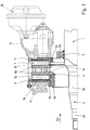
- the representations of an embodiment of a disc brake show a part of an axle beam 1, at the ends of which a steering knuckle 2 is trained.
- This steering knuckle 2 has two bearing seats 2a and 2b for the inner ring of preferably designed as tapered roller bearings Rolling bearings trained, for the sake of clarity on the Drawing are not shown.
- a wheel hub 3 on the steering knuckle 2 rotatably mounted, which in turn with bearing seats 3a and 3b is designed for the outer ring of the respective rolling bearing.
- the wheel hub 3 has a wheel flange 3c for the detachable attachment of one the drawing of the wheel, not shown, by means of wheel bolts; the for this Wheel bolts in the wheel flange 3c are provided in the holes 3d Recognize drawings.
- This brake disc 4 in turn includes one Brake disc hub 4a with the axial recesses 3f des Wheel hub neck 3e corresponding, axially extending projections 4d is provided, which are shown in Fig. 6. Also includes the brake disc 4 a friction ring 4b, which in the exemplary embodiment has a cooling channel 4c is provided.
- a retaining ring 8 is provided, the z. B. by means of screws 8a to End face of the wheel hub neck 3e can be screwed on (see FIG. 1).
- the Retaining ring 8 can also be designed as a magnet wheel for an ABS brake system be.
- a mounting flange 5 for a brake caliper carrier 6 is on the axle body 1 arranged with a shaft for receiving two brake blocks 7th is trained.
- Each brake pad 7 consists of a brake pad carrier 7a and the actual brake pad 7b.
- the brake caliper carrier 6 is shown in perspective in FIG. 8.
- This Illustration shows that the brake caliper carrier two flanges 6a comprises, via which it can be screwed to the mounting flange 5, the is in turn welded to the axle body 1.
- the brake caliper bracket 6 is screwed onto the mounting flange 5 on each side by means of three screws which are shown in FIGS. 7 and 8 are indicated.
- the brake caliper carrier 6 further includes a front Connecting web 6b and a rear connecting web 6c, which are extend between the two flanges 6a and one between them Have free space for the friction ring 4b of the brake disc 4.
- the top of the Connecting webs 6b and 6c serves as a bearing surface for the brake pads 7, the in the tangential direction of the brake caliper 6 by radially in pairs protruding stops 6d are guided.
- FIGS. 1 to 5 With dash-dotted lines is in FIGS. 1 to 5 for completeness a shown in longitudinal section brake caliper 9, which as in the axial Direction floating frame is executed and therefore is relatively movably mounted on the brake caliper carrier 6.
- Brake caliper 9 With the help of Brake caliper 9 is applied to the two brake pads 7 braking force through the piston one also shown in dash-dotted lines Brake cylinder 10 generated.
- the braking force of the brake cylinder piston is on the one hand directly on the inner brake pad 7 and on the other hand indirectly via the brake caliper 9 onto the external brake pad 7 exercised.
- To secure the brake pads 7 within their in the brake caliper carrier 6 Keep trained shaft is a retaining spring for each brake pad 7 11 provided that according to FIG. 6 on the respective brake pad carrier 7a of the Brake pad 7 is placed. Both retaining springs 11 are made together a bracket 12 provided on the brake caliper 9 in its operative position burdened and fixed. This situation is best seen in Fig. 1.
- FIG. 1 shows the operating state of the Disc brake shows.
- the first is according to FIG complete wheel hub 3 removed from steering knuckle 2. This is the first thing required, the retaining ring 8 by unscrewing the screws 8a Loosen wheel hub neck 3e.
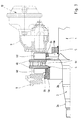
- the complete wheel hub 3 together with the rolling bearings and seals, not shown, and the wheel, also not shown, by means of the axle nut from the steering knuckle 2 are subtracted, which in the exemplary embodiment on the wheel hub neck 3e formed recesses 3f axially from the on the brake disc hub 4a trained projections 4d slide out.
- the brake disc 4 held in a suitable manner in their position shown in Fig. 1. After pulling off the hub 3 results in the state shown in FIG. 2.
- the brake caliper carrier 6 and the axial distance between the front and rear part of the brake caliper carrier 6 are coordinated with one another 5 with its brake caliper carrier 6 opposite lower half towards the free end of the Steering knuckle 2 pivoted and finally out of the brake caliper carrier 6 removed and removed via the knuckle 2.
- the rear connecting web 6c is in its central region in axial, offset from the brake disc 4 direction.
- This Offset V is shown in Fig. 5.
- the offset V of the rear Connecting web 6c can either by an arcuate design and / or by a return.
- this shows Embodiment that the front connecting web 6b narrower, however can be formed higher than the rear connecting web 6c, whereby removing or inserting the brake disc 4 into the brake caliper carrier 6 still relieved.
- the radial distance of the front Connecting web 6b of the brake caliper carrier 6 from the steering knuckle 2 larger than that of the rear connecting web 6c.
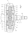
- the friction ring 4b of the brake disk 4 at least in one, but preferably in several sub-areas at least one friction surface with recesses 4f or bevels 4g Mistake.
- the embodiment shown in Fig. 9 shows that the upper and lower edge of the inner friction ring 4b with bevels 4g is carried out and that in the central region of the front friction ring 4b secant recess 4f is provided.
Abstract
Description
- Fig. 1
- einen Längsschnitt durch die obere Hälfte einer Scheibenbremse im Betriebszustand,
- Fig. 2
- einen der Fig. 1 entsprechenden Längsschnitt, nachdem die Radnabe vom Achsschenkel abgezogen worden ist,
- Fig. 3
- einen weiteren, den Fig. 1 und 2 entsprechenden Längsschnitt nach Entfernen der Bremsbeläge,
- Fig. 4
- einen weiteren Längsschnitt nach Aufheben der Positionierung der Bremsscheibe und Absenken der Bremsscheibe auf den Achsschenkel,
- Fig. 5
- einen den vorangegangenen Darstellungen entsprechenden Längsschnitt mit nach vorn verschwenkter und aus dem Bremssattelträger herausbewegter Bremsscheibe,
- Fig. 6
- eine Vorderansicht gemäß dem Pfeil VI in Fig. 2,
- Fig. 7
- eine Draufsicht gemäß dem Pfeil VII in Fig. 6,
- Fig. 8
- eine perspektivische Ansicht des Bremssattelträgers und
- Fig. 9
- eine in der oberen Hälfte geschnittene Seitenansicht einer Bremsscheibe.
- 1
- Achskörper
- 2
- Achsschenkel
- 2a
- Lagersitz
- 2b
- Lagersitz
- 3
- Radnabe
- 3a
- Lagersitz
- 3b
- Lagersitz
- 3c
- Radflansch
- 3d
- Bohrung
- 3e
- Radnabenhals
- 3f
- Vertiefung
- 4
- Bremsscheibe
- 4a
- Bremsscheibennabe
- 4b
- Reibring
- 4c
- Kühlkanal
- 4d
- Vorsprung
- 4f
- Ausnehmung
- 4g
- Abschrägung
- 5
- Befestigungsflansch
- 6
- Bremssattelträger
- 6a
- Flansch
- 6b
- Verbindungssteg, vorderer
- 6c
- Verbindungssteg, hinterer
- 6d
- Anschlag
- 7
- Bremsklotz
- 7a
- Bremsbelagträger
- 7b
- Bremsbelag
- 8
- Haltering
- 8a
- Schraube
- 9
- Bremssattel
- 10
- Bremszylinder
- 11
- Haltefeder
- 12
- Haltebügel
- V
- Versatz
Claims (11)
- Verfahren zum Wechsel der Bremsscheibe (4) einer Scheibenbremse, insbesondere von Nutzfahrzeugen, deren Bremsscheibe (4) aus einem Reibring (4b) und einer Bremsscheibennabe (4a) besteht, über die die Bremsscheibe (4) an einer auf einem Achsschenkel (2) drehbar gelagerten Radnabe (3) befestigt ist, die einen Radflansch (3c) zur lösbaren Befestigung eines Rades aufweist, wobei die Bremsscheibe (4) im Bereich ihres Reibringes (4b) mit zwei Bremsbelägen (7b) zusammenwirkt, die mit ihren Bremsbelagträgern (7a) in einem Schacht eines Bremssattelträgers (6) angeordnet sind, der an einem Befestigungsflansch (5) eines Achskörpers (1) befestigt ist und die Betätigungseinrichtung der Scheibenbremse trägt,
dadurch gekennzeichnet,daß die Radnabe (3) unter Trennung von der Bremsscheibennabe (4a) der in ihrer Position festgehaltenen Bremsscheibe (4) vom Achsschenkel (2) abgezogen wird,daß danach die Bremsbelagträger (7a) mit den Bremsbelägen (7b) aus dem Schacht des Bremssattelträgers (6) entfernt werdenund daß anschließend die Positionierung der Bremsscheibe (4) aufgehoben, die Bremsscheibe (4) in Richtung auf den Achsschenkel (2) abgesenkt und die dem Bremssattelträger (6) gegenüberliegende Hälfte der Bremsscheibe (4) in Richtung auf das freie Ende des Achsschenkels (2) verschwenkt und schließlich die Bremsscheibe (4) aus dem Bremssattelträger (6) entnommen und über den Achsschenkel (2) entfernt wird. - Verfahren nach Anspruch 1, dadurch gekennzeichnet, daß die Radnabe (3) zusammen mit dem am Radflansch (3c) montierten Rad vom Achsschenkel (2) abgezogen wird.
- Scheibenbremse zur Durchführung des Verfahrens nach Anspruch 1 oder 2, dadurch gekennzeichnet, daß die Abmessungen einerseits der Höhe und der axialen Dicke des Reibringes (4b) der Bremsscheibe (4) und andererseits des radialen Abstandes zwischen dem Achsschenkel (2) und dem dem Radflansch (3c) benachbarten vorderen Teil des Bremssattelträgers (6) sowie des axialen Abstandes zwischen vorderem und hinterem Teil des Bremssattelträgers (6) aufeinander abgestimmt sind.
- Scheibenbremse nach Anspruch 3 mit einem Bremssattelträger (6), der zwei Flansche (6a) zur Befestigung am Befestigungsflansch (5) des Achskörpers (1) und einen vorderen sowie einen hinteren Verbindungssteg (6b, 6c) zwischen diesen Flanschen (6a) aufweist, die den Schacht für die Bremsbelagträger (7a) bilden, dadurch gekennzeichnet, daß der hintere Verbindungssteg (6c) in seinem mittleren Bereich in axialer, von der Bremsscheibe (4) wegweisender Richtung versetzt ausgebildet ist.
- Scheibenbremse nach Anspruch 4, dadurch gekennzeichnet, daß der Versatz (V) des hinteren Verbindungssteges (6c) durch eine bogenförmige Ausbildung erfolgt.
- Scheibenbremse nach Anspruch 4, dadurch gekennzeichnet, daß der Versatz (V) des hinteren Verbindungssteges (6c) durch einen Rücksprung erfolgt.
- Scheibenbremse nach einem der Ansprüche 3 bis 6, dadurch gekennzeichnet, daß der vordere Verbindungssteg (6b) schmaler, aber höher als der hintere Verbindungssteg (6c) ausgebildet ist.
- Scheibenbremse nach mindestens einem der Ansprüche 3 bis 7, dadurch gekennzeichnet, daß der radiale Abstand des vorderen Verbindungssteges (6b) des Bremssattelträgers (6) vom Achsschenkel (2) größer als der des hinteren Verbindungssteges (6c) ist.
- Scheibenbremse nach mindestens einem der Ansprüche 3 bis 8, dadurch gekennzeichnet, daß der Reibring (4b) der Bremsscheibe (4) zumindest in einem Teilbereich seines Umfanges an mindestens einer Reibfläche mit Ausnehmungen (4f) bzw. Abschrägungen (4g) versehen ist.
- Scheibenbremse nach mindestens einem der Ansprüche 3 bis 9, dadurch gekennzeichnet, daß die Bremsscheibennabe (4a) über axial verlaufende Vorsprünge (4d) und/oder Vertiefungen (3f) mit dem Radnabenhals (3e) verdrehfest verbunden ist.
- Scheibenbremse nach Anspruch 10, dadurch gekennzeichnet, daß die Bremsscheibennabe (4a) in Richtung auf den Radflansch (3c) der Radnabe (3) mit einer axialen Verlängerung versehen ist.
Applications Claiming Priority (2)
| Application Number | Priority Date | Filing Date | Title |
|---|---|---|---|
| DE19652694A DE19652694C2 (de) | 1996-12-18 | 1996-12-18 | Anordnung einer Bremsscheibe an einer Radnabe |
| DE19652694 | 1996-12-18 |
Publications (3)
| Publication Number | Publication Date |
|---|---|
| EP0849486A2 true EP0849486A2 (de) | 1998-06-24 |
| EP0849486A3 EP0849486A3 (de) | 2000-05-03 |
| EP0849486B1 EP0849486B1 (de) | 2002-04-17 |
Family
ID=7815143
Family Applications (2)
| Application Number | Title | Priority Date | Filing Date |
|---|---|---|---|
| EP97121038A Expired - Lifetime EP0849486B1 (de) | 1996-12-18 | 1997-12-01 | Verfahren zum Wechsel der Bremsscheibe einer Scheibenbremse sowie zugehörige Scheibenbremse |
| EP97121039A Expired - Lifetime EP0849487B1 (de) | 1996-12-18 | 1997-12-01 | Anordnung einer Bremsscheibe an einer Radnabe |
Family Applications After (1)
| Application Number | Title | Priority Date | Filing Date |
|---|---|---|---|
| EP97121039A Expired - Lifetime EP0849487B1 (de) | 1996-12-18 | 1997-12-01 | Anordnung einer Bremsscheibe an einer Radnabe |
Country Status (9)
| Country | Link |
|---|---|
| US (1) | US6032768A (de) |
| EP (2) | EP0849486B1 (de) |
| CN (2) | CN1193581A (de) |
| AU (2) | AU4841497A (de) |
| BR (2) | BR9706140A (de) |
| DE (3) | DE19652694C2 (de) |
| ES (2) | ES2175250T3 (de) |
| TR (2) | TR199701640A2 (de) |
| ZA (2) | ZA9711339B (de) |
Cited By (7)
| Publication number | Priority date | Publication date | Assignee | Title |
|---|---|---|---|---|
| DE19822606C1 (de) * | 1998-05-20 | 1999-05-06 | Porsche Ag | Bremseinrichtung für Räder von Fahrzeugen |
| DE29924547U1 (de) * | 1999-04-01 | 2003-10-16 | Bpw Bergische Achsen Kg | Bremseinrichtung für Räder von Fahrzeugen |
| EP1564429A1 (de) * | 2004-02-12 | 2005-08-17 | Deere & Company | Trägerplatte und Verfahren zur Befestigung eines Scheibenbremssattels an einer Achse |
| DE102004016826A1 (de) * | 2004-04-01 | 2005-10-27 | Daimlerchrysler Ag | Bremsvorrichtung |
| DE102005059247A1 (de) * | 2005-12-12 | 2007-06-14 | Knorr-Bremse Systeme für Nutzfahrzeuge GmbH | Bremsvorrichtung |
| DE102007047794A1 (de) | 2007-11-15 | 2009-05-20 | Zf Friedrichshafen Ag | Anordnung zur Befestigung einer Bremsvorrichtung an einem Radträger eines Fahrzeuges |
| EP2236369A1 (de) | 2009-04-02 | 2010-10-06 | Knorr-Bremse Systeme für Nutzfahrzeuge GmbH | Verbindung einer Bremse mit einer Radachse eines Kraftfahrzeugs |
Families Citing this family (22)
| Publication number | Priority date | Publication date | Assignee | Title |
|---|---|---|---|---|
| DE19929390B4 (de) | 1999-06-28 | 2004-05-06 | Otto Sauer Achsenfabrik Keilberg | Bremsscheibenanordnung |
| TW571997U (en) * | 2003-02-20 | 2004-01-11 | Yan Luen Ind Co Ltd | Improved fassembling and positioning structure for brake apparatus of wheel axle |
| DE102004002571B4 (de) * | 2003-04-28 | 2015-02-26 | Bpw Bergische Achsen Kg | Bremssattel für eine Scheibenbremse |
| DE10324771A1 (de) * | 2003-05-31 | 2004-12-16 | Bpw Bergische Achsen Kg | Anordnung einer Bremsscheibe an einer Radnabe |
| WO2005038282A1 (en) * | 2003-10-22 | 2005-04-28 | Groupe Newtech International Inc. | Method of replacing the rotor disk of a disk brake assembly |
| DE10350928B4 (de) * | 2003-10-31 | 2012-10-11 | Zf Friedrichshafen Ag | Hinterachsradkopf für Einfach- und Zwillingsbereifung |
| DE102004034361B3 (de) * | 2004-07-16 | 2006-02-09 | Knorr-Bremse Systeme für Nutzfahrzeuge GmbH | An einer Radnabe eines Kraftfahrzeuges anschließbares Polrad |
| US9291227B2 (en) * | 2005-09-30 | 2016-03-22 | Performance Friction Corporation | Brake rotor and abs tone ring attachment assembly that promotes in plane uniform torque transfer distribution |
| DE102008014857B4 (de) * | 2008-03-18 | 2010-01-28 | Knorr-Bremse Systeme für Nutzfahrzeuge GmbH | Bremsscheiben/Nabenverbindung |
| DE102008017360B3 (de) | 2008-04-04 | 2009-07-30 | Knorr-Bremse Systeme für Nutzfahrzeuge GmbH | Anordnung einer Bremsscheibe an einer Radnabe |
| US20100018814A1 (en) * | 2008-07-03 | 2010-01-28 | Pagles Jonathan O | Vehicle wheel assembly, brake caliper assembly and related methods |
| MX2011010737A (es) * | 2009-05-29 | 2011-12-06 | Hendrickson Usa Llc | Husillo de eje de precision y ensamble de extremo de rueda para vehiculos de trabajo pesado. |
| US20110062772A1 (en) * | 2009-09-14 | 2011-03-17 | Hendrickson Usa, L.L.C. | Bearing retainer for heavy-duty vehicle wheel end assembly |
| US20110291467A1 (en) * | 2010-06-01 | 2011-12-01 | Consolidated Metco, Inc. | Wheel hub assembly |
| DE102011000626B4 (de) * | 2011-02-10 | 2021-12-09 | Bpw Bergische Achsen Kg | Radlagerung für ein Fahrzeugrad sowie Radnabe für die Befestigung eines Fahrzeugrades |
| DE102011112182A1 (de) | 2011-09-01 | 2013-03-07 | Daimler Ag | Anordnung einer Bremsscheibe an einer Radnabe |
| DE102013113550B4 (de) | 2013-12-05 | 2022-02-03 | Knorr-Bremse Systeme für Nutzfahrzeuge GmbH | Anordnung einer Bremsscheibe an einer Radnabe |
| WO2018222389A1 (en) * | 2017-06-01 | 2018-12-06 | Hendrickson Usa, L.L.C. | Brake component positioning assembly |
| DE102017113128A1 (de) * | 2017-06-14 | 2018-12-20 | Knorr-Bremse Systeme für Nutzfahrzeuge GmbH | Bremsscheiben-/Nabenverbindung |
| DE102017116309B4 (de) * | 2017-07-18 | 2020-04-16 | Saf-Holland Gmbh | Radnabe und ein System aus Radnabe und Bremselement |
| CN110905945B (zh) * | 2019-12-11 | 2021-10-26 | 隆中控股集团股份有限公司 | 一种轮毂盘总成或制动盘的拆换方法 |
| CN111301367A (zh) * | 2020-03-30 | 2020-06-19 | 吉林大学 | 一种用于碳纤维复合材料制动盘的双向浮动固定结构 |
Family Cites Families (14)
| Publication number | Priority date | Publication date | Assignee | Title |
|---|---|---|---|---|
| US3780834A (en) * | 1973-01-15 | 1973-12-25 | Gen Motors Corp | Disc brake assembly |
| FR2264285A1 (en) * | 1974-03-13 | 1975-10-10 | Citroen Sa | Motor vehicle wheel speed measurer - uses magnetic detector with ferromagnetic teeth integral with disc assembly |
| US3978945A (en) * | 1974-09-17 | 1976-09-07 | The B. F. Goodrich Company | Brake disc mounting |
| US3946837A (en) * | 1974-12-26 | 1976-03-30 | Rohr Industries, Inc. | Disc brake and actuator assembly |
| DE2610811C2 (de) * | 1976-03-15 | 1985-12-05 | Hermann Dr.-Ing. 7412 Eningen Klaue | Vollbelagscheibenbremse, insbesondere für Nutzfahrzeuge |
| US4049085A (en) * | 1976-08-10 | 1977-09-20 | Safety Racing Equipment, Incorporated | Caliper brake with assembly for rotor attachment to hub |
| DE2804209A1 (de) * | 1978-02-01 | 1979-08-02 | Kloeckner Humboldt Deutz Ag | Teilbelagscheibenbremse, insbesondere fuer eine getriebewelle und/oder die achsantriebswelle eines land- und/oder bauwirtschaftlich nutzbaren kraftfahrzeuges |
| GB2021218B (en) * | 1978-05-13 | 1982-07-07 | Girling Ltd | Disc brakes for vehicles |
| JPS6148622A (ja) * | 1984-08-14 | 1986-03-10 | Dia Hitoko Konpojitsuto Kk | 複合ブレ−キデイスク |
| DE3605806A1 (de) * | 1986-02-22 | 1987-09-03 | Porsche Ag | Befestigungsvorrichtung fuer eine bremsscheibe |
| DE4230012C2 (de) * | 1992-09-08 | 1999-08-26 | Knorr Bremse Systeme | ABS-überwachtes Fahrzeugrad |
| DE4338593A1 (de) * | 1993-11-11 | 1995-05-18 | Knorr Bremse Systeme | Bremsscheibe für eine Scheibenbremse |
| DE4433743A1 (de) * | 1994-09-21 | 1996-03-28 | Perrot Bremsen Gmbh | Anordnung zum Halten einer Radfelge |
| SE508173C2 (sv) * | 1996-06-17 | 1998-09-07 | Volvo Lastvagnar Ab | Hjulnav och bromsskiveanordning samt fjädrande låsning för ett fordonshjul |
-
1996
- 1996-12-18 DE DE19652694A patent/DE19652694C2/de not_active Expired - Fee Related
-
1997
- 1997-12-01 DE DE59706750T patent/DE59706750D1/de not_active Expired - Lifetime
- 1997-12-01 EP EP97121038A patent/EP0849486B1/de not_active Expired - Lifetime
- 1997-12-01 EP EP97121039A patent/EP0849487B1/de not_active Expired - Lifetime
- 1997-12-01 DE DE59707040T patent/DE59707040D1/de not_active Expired - Lifetime
- 1997-12-01 ES ES97121039T patent/ES2175250T3/es not_active Expired - Lifetime
- 1997-12-01 ES ES97121038T patent/ES2175249T3/es not_active Expired - Lifetime
- 1997-12-14 BR BR9706140-9A patent/BR9706140A/pt not_active Application Discontinuation
- 1997-12-17 ZA ZA9711339A patent/ZA9711339B/xx unknown
- 1997-12-17 BR BR9706383-5A patent/BR9706383A/pt not_active Application Discontinuation
- 1997-12-17 AU AU48414/97A patent/AU4841497A/en not_active Abandoned
- 1997-12-17 CN CN97125531A patent/CN1193581A/zh active Pending
- 1997-12-17 AU AU48415/97A patent/AU4841597A/en not_active Abandoned
- 1997-12-17 ZA ZA9711341A patent/ZA9711341B/xx unknown
- 1997-12-17 CN CN97125530A patent/CN1185389A/zh active Pending
- 1997-12-18 TR TR97/01640A patent/TR199701640A2/xx unknown
- 1997-12-18 US US08/993,347 patent/US6032768A/en not_active Expired - Fee Related
- 1997-12-18 TR TR97/01641A patent/TR199701641A3/tr unknown
Non-Patent Citations (1)
| Title |
|---|
| None |
Cited By (11)
| Publication number | Priority date | Publication date | Assignee | Title |
|---|---|---|---|---|
| DE19822606C1 (de) * | 1998-05-20 | 1999-05-06 | Porsche Ag | Bremseinrichtung für Räder von Fahrzeugen |
| WO1999059852A1 (de) * | 1998-05-20 | 1999-11-25 | Dr. Ing. H.C.F. Porsche Aktiengesellschaft | Bremseinrichtung für räder von fahrzeugen |
| DE29924547U1 (de) * | 1999-04-01 | 2003-10-16 | Bpw Bergische Achsen Kg | Bremseinrichtung für Räder von Fahrzeugen |
| EP1564429A1 (de) * | 2004-02-12 | 2005-08-17 | Deere & Company | Trägerplatte und Verfahren zur Befestigung eines Scheibenbremssattels an einer Achse |
| DE102004016826A1 (de) * | 2004-04-01 | 2005-10-27 | Daimlerchrysler Ag | Bremsvorrichtung |
| US7673724B2 (en) | 2004-04-01 | 2010-03-09 | KNORR-BREMSE Systeme fuer Nutzfehrzeuge GmbH | Brake mechanism |
| DE102005059247A1 (de) * | 2005-12-12 | 2007-06-14 | Knorr-Bremse Systeme für Nutzfahrzeuge GmbH | Bremsvorrichtung |
| DE102005059247B4 (de) * | 2005-12-12 | 2008-04-30 | Knorr-Bremse Systeme für Nutzfahrzeuge GmbH | Bremsvorrichtung |
| DE102007047794A1 (de) | 2007-11-15 | 2009-05-20 | Zf Friedrichshafen Ag | Anordnung zur Befestigung einer Bremsvorrichtung an einem Radträger eines Fahrzeuges |
| EP2236369A1 (de) | 2009-04-02 | 2010-10-06 | Knorr-Bremse Systeme für Nutzfahrzeuge GmbH | Verbindung einer Bremse mit einer Radachse eines Kraftfahrzeugs |
| DE102009015940A1 (de) | 2009-04-02 | 2010-10-14 | Knorr-Bremse Systeme für Nutzfahrzeuge GmbH | Verbindung einer Bremse mit einer Radachse eines Kraftfahrzeugs |
Also Published As
| Publication number | Publication date |
|---|---|
| ZA9711339B (en) | 1998-06-23 |
| BR9706383A (pt) | 1999-09-08 |
| TR199701641A2 (xx) | 1999-10-21 |
| EP0849487B1 (de) | 2002-03-27 |
| AU4841497A (en) | 1998-06-25 |
| TR199701640A3 (tr) | 1999-10-21 |
| DE59706750D1 (de) | 2002-05-02 |
| AU4841597A (en) | 1998-06-25 |
| TR199701640A2 (xx) | 1999-10-21 |
| ES2175250T3 (es) | 2002-11-16 |
| US6032768A (en) | 2000-03-07 |
| CN1193581A (zh) | 1998-09-23 |
| BR9706140A (pt) | 2001-11-27 |
| TR199701641A3 (tr) | 1999-10-21 |
| DE19652694C2 (de) | 2001-01-18 |
| EP0849487A3 (de) | 1999-10-13 |
| EP0849487A2 (de) | 1998-06-24 |
| EP0849486B1 (de) | 2002-04-17 |
| CN1185389A (zh) | 1998-06-24 |
| ES2175249T3 (es) | 2002-11-16 |
| ZA9711341B (en) | 1998-06-23 |
| DE59707040D1 (de) | 2002-05-23 |
| DE19652694A1 (de) | 1998-06-25 |
| EP0849486A3 (de) | 2000-05-03 |
Similar Documents
| Publication | Publication Date | Title |
|---|---|---|
| EP0849486B1 (de) | Verfahren zum Wechsel der Bremsscheibe einer Scheibenbremse sowie zugehörige Scheibenbremse | |
| DE3340442C2 (de) | Fahrwerks-Baugruppe für die Anbringung von Radachsen und Bremsen bei Kraftfahrzeugen | |
| DE2504239B2 (de) | Hydraulische Betätigungsvorrichtung für eine Vollbelagscheibenbremse mit konischen Bremsflächen, insbesondere für Motorräder | |
| DE2449043B2 (de) | Bremsscheibenanordnung, insbesondere für Gleisfahrzeuge | |
| EP0636217B1 (de) | Verfahren zum herstellen einer bremsscheibe für eine scheibenbremse | |
| EP1155829A2 (de) | Austauschbare Zylinderelemente an elektrographischen Druckeinheiten | |
| DE2520768A1 (de) | Scheibenbremse sowie verfahren zur montage derselben | |
| DE19508034A1 (de) | Scheibenbremse für Fahrzeuge, insbesondere Schienenfahrzeuge | |
| EP1069334B1 (de) | Sicherungselement für Scheibenbremsklötze | |
| DE3402530C2 (de) | ||
| DE2547083A1 (de) | Scheibenbremse | |
| DE3436973A1 (de) | Bremsscheibenanordnung fuer eine innen umgreifende scheibenbremse, insbesondere fuer kraftfahrzeuge | |
| EP1080000B1 (de) | Bremseinrichtung für räder von fahrzeugen | |
| DE2320115B2 (de) | Befestigung einer Bremsscheibe einer Achsnabe für Scheibenbremsen in Schienenfahrzeugen | |
| DE2120433A1 (de) | Scheibenbremse | |
| DE2748195B2 (de) | Luftgekühlte Vollbelag-Scheibenbremse | |
| DE2526403A1 (de) | Vollbelagscheibenbremse mit umlaufendem bremsgehaeuse, insbesondere fuer kraftfahrzeuge | |
| DE2230571A1 (de) | Scheibenbremse fuer kraftfahrzeuge | |
| EP0564710A1 (de) | Kettenrad für Gelenkketten | |
| DE10324771A1 (de) | Anordnung einer Bremsscheibe an einer Radnabe | |
| DE2904957A1 (de) | Verfahren und einrichtung zum abrichten von bremsscheiben | |
| EP0001045B1 (de) | Nachstellvorrichtung für eine Teilbelag-Scheibenbremse | |
| EP0245672A1 (de) | Reibbelag-Scheibenbremse | |
| DE10027429A1 (de) | Mit einer Bremseinrichtung versehene, luftgefederte Achskonstruktion | |
| DE1530500C3 (de) | Scheibenbremse |
Legal Events
| Date | Code | Title | Description |
|---|---|---|---|
| PUAI | Public reference made under article 153(3) epc to a published international application that has entered the european phase |
Free format text: ORIGINAL CODE: 0009012 |
|
| AK | Designated contracting states |
Kind code of ref document: A2 Designated state(s): DE ES FR GB IT |
|
| AX | Request for extension of the european patent |
Free format text: AL;LT;LV;MK;RO;SI |
|
| PUAL | Search report despatched |
Free format text: ORIGINAL CODE: 0009013 |
|
| AK | Designated contracting states |
Kind code of ref document: A3 Designated state(s): AT BE CH DE DK ES FI FR GB GR IE IT LI LU MC NL PT SE |
|
| AX | Request for extension of the european patent |
Free format text: AL;LT;LV;MK;RO;SI |
|
| 17P | Request for examination filed |
Effective date: 20000619 |
|
| AKX | Designation fees paid |
Free format text: DE ES FR GB IT |
|
| 17Q | First examination report despatched |
Effective date: 20010124 |
|
| GRAG | Despatch of communication of intention to grant |
Free format text: ORIGINAL CODE: EPIDOS AGRA |
|
| GRAG | Despatch of communication of intention to grant |
Free format text: ORIGINAL CODE: EPIDOS AGRA |
|
| GRAH | Despatch of communication of intention to grant a patent |
Free format text: ORIGINAL CODE: EPIDOS IGRA |
|
| GRAH | Despatch of communication of intention to grant a patent |
Free format text: ORIGINAL CODE: EPIDOS IGRA |
|
| REG | Reference to a national code |
Ref country code: GB Ref legal event code: IF02 |
|
| GRAA | (expected) grant |
Free format text: ORIGINAL CODE: 0009210 |
|
| AK | Designated contracting states |
Kind code of ref document: B1 Designated state(s): DE ES FR GB IT |
|
| GBT | Gb: translation of ep patent filed (gb section 77(6)(a)/1977) |
Effective date: 20020417 |
|
| REF | Corresponds to: |
Ref document number: 59707040 Country of ref document: DE Date of ref document: 20020523 |
|
| ET | Fr: translation filed | ||
| REG | Reference to a national code |
Ref country code: ES Ref legal event code: FG2A Ref document number: 2175249 Country of ref document: ES Kind code of ref document: T3 |
|
| PLBE | No opposition filed within time limit |
Free format text: ORIGINAL CODE: 0009261 |
|
| STAA | Information on the status of an ep patent application or granted ep patent |
Free format text: STATUS: NO OPPOSITION FILED WITHIN TIME LIMIT |
|
| 26N | No opposition filed |
Effective date: 20030120 |
|
| PGFP | Annual fee paid to national office [announced via postgrant information from national office to epo] |
Ref country code: ES Payment date: 20081219 Year of fee payment: 12 |
|
| PGFP | Annual fee paid to national office [announced via postgrant information from national office to epo] |
Ref country code: IT Payment date: 20081223 Year of fee payment: 12 |
|
| PGFP | Annual fee paid to national office [announced via postgrant information from national office to epo] |
Ref country code: FR Payment date: 20081216 Year of fee payment: 12 |
|
| PGFP | Annual fee paid to national office [announced via postgrant information from national office to epo] |
Ref country code: GB Payment date: 20081219 Year of fee payment: 12 |
|
| GBPC | Gb: european patent ceased through non-payment of renewal fee |
Effective date: 20091201 |
|
| REG | Reference to a national code |
Ref country code: FR Ref legal event code: ST Effective date: 20100831 |
|
| PG25 | Lapsed in a contracting state [announced via postgrant information from national office to epo] |
Ref country code: FR Free format text: LAPSE BECAUSE OF NON-PAYMENT OF DUE FEES Effective date: 20091231 |
|
| PG25 | Lapsed in a contracting state [announced via postgrant information from national office to epo] |
Ref country code: GB Free format text: LAPSE BECAUSE OF NON-PAYMENT OF DUE FEES Effective date: 20091201 |
|
| REG | Reference to a national code |
Ref country code: ES Ref legal event code: FD2A Effective date: 20110330 |
|
| PG25 | Lapsed in a contracting state [announced via postgrant information from national office to epo] |
Ref country code: IT Free format text: LAPSE BECAUSE OF NON-PAYMENT OF DUE FEES Effective date: 20091201 |
|
| PG25 | Lapsed in a contracting state [announced via postgrant information from national office to epo] |
Ref country code: ES Free format text: LAPSE BECAUSE OF NON-PAYMENT OF DUE FEES Effective date: 20110317 |
|
| PG25 | Lapsed in a contracting state [announced via postgrant information from national office to epo] |
Ref country code: ES Free format text: LAPSE BECAUSE OF NON-PAYMENT OF DUE FEES Effective date: 20091202 |
|
| REG | Reference to a national code |
Ref country code: DE Ref legal event code: R082 Ref document number: 59707040 Country of ref document: DE Representative=s name: BUNGARTZ CHRISTOPHERSEN PARTNERSCHAFT MBB PATE, DE |
|
| PGFP | Annual fee paid to national office [announced via postgrant information from national office to epo] |
Ref country code: DE Payment date: 20170103 Year of fee payment: 20 |
|
| REG | Reference to a national code |
Ref country code: DE Ref legal event code: R071 Ref document number: 59707040 Country of ref document: DE |