EP0849101A2 - Radialer lkw-Reifen - Google Patents
Radialer lkw-Reifen Download PDFInfo
- Publication number
- EP0849101A2 EP0849101A2 EP97310274A EP97310274A EP0849101A2 EP 0849101 A2 EP0849101 A2 EP 0849101A2 EP 97310274 A EP97310274 A EP 97310274A EP 97310274 A EP97310274 A EP 97310274A EP 0849101 A2 EP0849101 A2 EP 0849101A2
- Authority
- EP
- European Patent Office
- Prior art keywords
- slope
- tyre
- heavy duty
- angle
- blocks
- Prior art date
- Legal status (The legal status is an assumption and is not a legal conclusion. Google has not performed a legal analysis and makes no representation as to the accuracy of the status listed.)
- Granted
Links
Images


Classifications
-
- B—PERFORMING OPERATIONS; TRANSPORTING
- B60—VEHICLES IN GENERAL
- B60C—VEHICLE TYRES; TYRE INFLATION; TYRE CHANGING; CONNECTING VALVES TO INFLATABLE ELASTIC BODIES IN GENERAL; DEVICES OR ARRANGEMENTS RELATED TO TYRES
- B60C11/00—Tyre tread bands; Tread patterns; Anti-skid inserts
- B60C11/03—Tread patterns
- B60C11/13—Tread patterns characterised by the groove cross-section, e.g. for buttressing or preventing stone-trapping
-
- B—PERFORMING OPERATIONS; TRANSPORTING
- B60—VEHICLES IN GENERAL
- B60C—VEHICLE TYRES; TYRE INFLATION; TYRE CHANGING; CONNECTING VALVES TO INFLATABLE ELASTIC BODIES IN GENERAL; DEVICES OR ARRANGEMENTS RELATED TO TYRES
- B60C11/00—Tyre tread bands; Tread patterns; Anti-skid inserts
- B60C11/03—Tread patterns
- B60C11/11—Tread patterns in which the raised area of the pattern consists only of isolated elements, e.g. blocks
-
- B—PERFORMING OPERATIONS; TRANSPORTING
- B60—VEHICLES IN GENERAL
- B60C—VEHICLE TYRES; TYRE INFLATION; TYRE CHANGING; CONNECTING VALVES TO INFLATABLE ELASTIC BODIES IN GENERAL; DEVICES OR ARRANGEMENTS RELATED TO TYRES
- B60C11/00—Tyre tread bands; Tread patterns; Anti-skid inserts
- B60C11/03—Tread patterns
- B60C11/13—Tread patterns characterised by the groove cross-section, e.g. for buttressing or preventing stone-trapping
- B60C11/1376—Three dimensional block surfaces departing from the enveloping tread contour
- B60C11/1384—Three dimensional block surfaces departing from the enveloping tread contour with chamfered block corners
-
- B—PERFORMING OPERATIONS; TRANSPORTING
- B60—VEHICLES IN GENERAL
- B60C—VEHICLE TYRES; TYRE INFLATION; TYRE CHANGING; CONNECTING VALVES TO INFLATABLE ELASTIC BODIES IN GENERAL; DEVICES OR ARRANGEMENTS RELATED TO TYRES
- B60C9/00—Reinforcements or ply arrangement of pneumatic tyres
- B60C9/18—Structure or arrangement of belts or breakers, crown-reinforcing or cushioning layers
- B60C9/20—Structure or arrangement of belts or breakers, crown-reinforcing or cushioning layers built-up from rubberised plies each having all cords arranged substantially parallel
- B60C9/2003—Structure or arrangement of belts or breakers, crown-reinforcing or cushioning layers built-up from rubberised plies each having all cords arranged substantially parallel characterised by the materials of the belt cords
- B60C9/2009—Structure or arrangement of belts or breakers, crown-reinforcing or cushioning layers built-up from rubberised plies each having all cords arranged substantially parallel characterised by the materials of the belt cords comprising plies of different materials
-
- Y—GENERAL TAGGING OF NEW TECHNOLOGICAL DEVELOPMENTS; GENERAL TAGGING OF CROSS-SECTIONAL TECHNOLOGIES SPANNING OVER SEVERAL SECTIONS OF THE IPC; TECHNICAL SUBJECTS COVERED BY FORMER USPC CROSS-REFERENCE ART COLLECTIONS [XRACs] AND DIGESTS
- Y10—TECHNICAL SUBJECTS COVERED BY FORMER USPC
- Y10S—TECHNICAL SUBJECTS COVERED BY FORMER USPC CROSS-REFERENCE ART COLLECTIONS [XRACs] AND DIGESTS
- Y10S152/00—Resilient tires and wheels
- Y10S152/902—Non-directional tread pattern having no circumferential rib and having blocks defined by circumferential grooves and transverse grooves
Definitions
- the present invention relates to a pneumatic tyre, more particularly to a heavy duty radial tyre with an improved tread portion having resistance to uneven wear and tear-off and improved wet performance.
- an object of the present invention to provide a heavy duty radial tyre, in which the resistance to uneven wear and tear-off, wet performance, and appearance or tread pattern's image are improved in a well balanced manner.
- a heavy duty radial tyre comprises a tread portion which is provided with blocks having acute angled corners between a pair of edge lines, characterised in that the acute angled corners are provided with a down slop which becomes steeper from the radially outside to the inside of the tyre.
- the angle may change step-by-step or gradually.
- the size of the slope is 1 to 10 mm when measured along the one edge line (3A), and 1 to 10 mm when measured along the other edge line (3B), and 5 to 13 mm when measured in the radial direction of the tyre.
- the carcass 20 comprises at least one radial or semiradial ply made of steel cords or organic fibre cords, e.g. polyester, aromatic polyamide rayon, nylon, or the like being arranged at an angle of from 70 to 90 degrees with respect to the tyre equator C and turned up around the bead cores 19 from the axially inside to the outside of the tyre.
- steel cords or organic fibre cords e.g. polyester, aromatic polyamide rayon, nylon, or the like
- the belt 21 comprises two to four plies including at least two crossed plies, each of which is made of organic fibre cords, e.g. nylon, polyester, rayon, aromatic polyamide or the like or steel cords laid in parallel with each other at a predetermined inclination angle with respect to the tyre equator C.
- organic fibre cords e.g. nylon, polyester, rayon, aromatic polyamide or the like or steel cords laid in parallel with each other at a predetermined inclination angle with respect to the tyre equator C.
- four belt plies 21A, 21B, 21C and 21D are disposed, and the cord inclining direction is reversed between the belt plies 21B and 21C.
- the tread portion 15 as shown in Fig.2 is provided with circumferential rows 12 of blocks 2 which are divided by circumferential grooves 23, 24 and 25 and axial grooves 26, and each block 2 has acute angled corners (B).
- the so called block type tread pattern is formed, which is however only an example of the tread pattern. It is possible to employ another type of tread pattern, for example, a combination of block rows and circumferentially continuously extending ribs.
- a down slope 9 which becomes steeper toward the radially innerside of the tyre is formed on the acute angled corners (B).
- all the acute angled corners (B) adjoining the circumferential grooves are provided with a down slope 9. It is however possible that some of the corners (B) are not provided with such a slope. It is also possible that all the acute angled corners existing in the tread are provided with such a slope.
- a pair of main grooves 23 extending continuously in the tyre circumferential direction are disposed one on each side of the tyre equator C.
- a pair of narrow grooves 24 extending continuously in the tyre circumferential direction are each disposed between the tyre equator C and the main grooves 23.
- a pair of narrow grooves 25 extending continuously in the tyre circumferential direction are each disposed between the tread edge E and the main grooves 23; and axial grooves 26 are provided extending from the narrow grooves 24 to the tread edges E.
- a first row 12M of blocks 2A is formed between each of the narrow grooves 24 and the adjacent main groove 23; a second row 12N of blocks 2B is formed between each of the narrow grooves 25 and the adjacent main groove 23; a third row 12L of blocks 2C is formed between each of the narrow grooves 25 and the adjacent tread edge E; and a rib 31 extending continuously in the tyre circumferential direction along the tyre equator C is formed between the two narrow grooves 24.
- the rib 31 is provided with sipes 27 extending from the axially inner ends of the axial grooves 26 to the tyre equator C and circumferentially displaced relative to one another, and sipes 29 extending on the tyre equator C between circumferentially adjacent sipes 27 to form zigzag sipes 30 as shown in Fig.2.
- the main groove 23 is staggered at the crossing points with the axial grooves 26, and the segments between the axial grooves 26 are straight and inclined in one direction. Further, in the region between the narrow grooves 24 and 25, the axial grooves 26 are substantially straight and inclined in one direction. Furthermore, in the region between the narrow groove 25 and the tread edge E, the axial grooves 26 are straight and inclined in one direction which is different from the above-mentioned direction. As a result, the blocks 2A, 2B and 2C have a trapezoidal configuration. The trapezoid of the blocks 2A is reverse to that of the blocks 2B.
- each of the blocks is provided on each side in the circumferential direction with one acute angled corner (B) which is defined between a circumferentially extending edge line 3A and an axially extending edge line 3B as shown in Fig.3.
- the blocks 2A and 2B are provided on all the acute angled corners (B) with the down slope 9, but the blocks 2C are provided with the down slope 9 on acute angled corners (B) on the inner side of the axial direction.
- the acute angled corners adjoining the tread edges are not provided with a down slope.
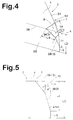
- Figs.4 and 5 show an example of the down slope 10 according to this invention.
- the slope 9 is a double slope composed of a radially outer gentle slope 9A and a radially inner steep slope 9B.
- the outer slope 9A is a trapezoidal flat plane
- the inner slope 9B is a triangle flat plane.
- the slope 9 as a whole seems like a bent isosceles triangle.
- Fig.6 shows another example of the slope 9.
- the slope 9 is a triple slope composed of the radially outer trapezoidal gentle slope 9A, the radially inner triangle steep slope 9B and a trapezoidal middle slopes 9C therebetween.
- the slope 9 can be composed of four or more slopes.
- Fig.7 shows still another example of the slope 9, which is a double slope similar to the former example of Fig.4, but the outer and inner slopes 9A and 9B are convexly curved in a horizontal plane parallel with the tread face.
- Figs.8 and 9 shows still more another example of the slope 9.
- the slope 9 becomes steeper gradually in contrast to the above-explained step-by-step change.
- the slope 9 is straight, not curved, in a horizontal plane in contrast to Fig.7.
- the slope 9 is curved in a horizontal plane and a perpendicular plane like a combination of the examples of Fig.7 and Fig.8.
- the radially inner slope 9B preferably has an inclination angle ⁇ min in the range of from 10 to 30 degrees.
- the radially outer slope 9A has an inclination angle ⁇ 1 in the range of from 30 to 70 degrees.
- the angle ⁇ 1 is preferably in the range of from 30 to 50 degrees.
- the angle ⁇ 1 is in the range of from 50 to 70 degrees
- the middle slope 9C has an inclination angle ⁇ 2 in the range of from 30 to 50 degrees.
- the inclination angle ⁇ gradually changes from substantially 90 degrees at the top to substantially 0 degree at the radially inner end point I.
- the dimensions of the cut-off rubber that is, the size of the slope 9 is defined as follows.
- a point (A) and distances La, Lb and Lc relating to the slope size are defined beforehand.
- the point (A) is an intersecting point of the three edge lines 3A, 3B and 5 of the block 2.
- the distance La is between the point (A) and an intersecting point of the line 3A and the upper edge 7 of the slope 9.
- the distance Lb is between the point (A) and an intersecting point of the line 3B and the upper edge 7 of the slope 9.
- the distance Lc is a radial distance between the point (A) and the radially inner extreme end of the slope 9.
- the distance Lc is the radial extent of the slope 9.
- the distance La is the distance between the radially inner extreme end of the slope 9 and the intersecting point of the edge line 3A and the upper edge 7 which distance is projected on the tread face.
- the distance Lb is the distance between the radially inner extreme end of the slope 9 and the intersecting point of the edge line 3B and the upper edge 7 which distance is projected on the tread face.
- the distances La and Lb are preferably set in the range of from 1 to 10 mm, more preferably 3 to 6 mm. If the distances La and Lb are less than 1 mm, it becomes difficult to obtain the required resistance to uneven wear and tear-off. If the distances La and Lb are more than 10 mm, not only the wet performance is liable to be deteriorated but also the tread pattern becomes a bad image. For the similar reason, the distance La is preferably set in the range of from 0.05 to 0.15 times the block edge length LA, and the distance Lb is preferably set in the range of from 0.10 to 0.30 times the block edge length LB.
- the distance Lc is preferably set in the range of from 0.25 to 0.50 times the blocks height LD and in the range of from 5 to 13 mm. If Lc is less than 5 mm or Lc/LD is less than 0.25, it becomes difficult to obtain the required resistance to uneven wear and tear-off. If Lc is more than 13 mm or Lc/LD is more than 0.50, not only the wet performance is liable to be deteriorated but also the tread pattern becomes a bad image.
- inclination angles ⁇ , ⁇ 1, ⁇ 2, amin of the slopes 9 are defined as an angle of a tangential line to the slope 9 measured with respect to a perpendicular line L, wherein both the lines are in a perpendicular plane F which is at a right angle to the slope 9 in a horizontal plane.
- the angle ⁇ is less than the above-mentioned range, the resistance to uneven wear and tear-off is liable to decrease. If the angle ⁇ is over the above-mentioned range, the resistance to uneven wear and tear-off and tread pattern's image becomes worse.
- Test tyres of size 285/75R24.5 having the same internal structure as shown in Fig.1 and the tread pattern of Fig.2 were made and tested.
- the carcass was composed of a single radial ply of steel cords (3/0.20+7/0.23), and the belt was composed of four plies of steel cords (1X3/0.20+6/0.35).
- the other specifications and test results are shown in Table 1.
- the tread pattern image was evaluated into five ranks (larger is better) on the basis of a feeling whether the acute angle corners are seen to be sharp or dull.
- the resistance to uneven wear and tear-off, wet performance, and pattern's image can be improved in a well balanced manner.
Landscapes
- Engineering & Computer Science (AREA)
- Mechanical Engineering (AREA)
- Tires In General (AREA)
Applications Claiming Priority (3)
| Application Number | Priority Date | Filing Date | Title |
|---|---|---|---|
| JP339136/96 | 1996-12-19 | ||
| JP33913696 | 1996-12-19 | ||
| JP33916396A JP3158061B2 (ja) | 1996-12-19 | 1996-12-19 | 重荷重用ラジアルタイヤ |
Publications (3)
| Publication Number | Publication Date |
|---|---|
| EP0849101A2 true EP0849101A2 (de) | 1998-06-24 |
| EP0849101A3 EP0849101A3 (de) | 1999-03-17 |
| EP0849101B1 EP0849101B1 (de) | 2003-03-05 |
Family
ID=18324842
Family Applications (2)
| Application Number | Title | Priority Date | Filing Date |
|---|---|---|---|
| EP97310272A Withdrawn EP0849100A1 (de) | 1996-12-19 | 1997-12-18 | LKW-Reifen |
| EP97310274A Expired - Lifetime EP0849101B1 (de) | 1996-12-19 | 1997-12-18 | Radialer lkw-Reifen |
Family Applications Before (1)
| Application Number | Title | Priority Date | Filing Date |
|---|---|---|---|
| EP97310272A Withdrawn EP0849100A1 (de) | 1996-12-19 | 1997-12-18 | LKW-Reifen |
Country Status (4)
| Country | Link |
|---|---|
| US (1) | US6138728A (de) |
| EP (2) | EP0849100A1 (de) |
| JP (2) | JPH10175405A (de) |
| DE (1) | DE69719474T2 (de) |
Cited By (9)
| Publication number | Priority date | Publication date | Assignee | Title |
|---|---|---|---|---|
| EP0925957A2 (de) * | 1997-12-25 | 1999-06-30 | Bridgestone Corporation | Luftreifen |
| EP1036674A2 (de) * | 1999-03-16 | 2000-09-20 | Sumitomo Rubber Industries Ltd. | Luftreifen |
| EP1186449A2 (de) * | 2000-09-06 | 2002-03-13 | The Goodyear Tire & Rubber Company | Luftreifen mit offenem Laufflächenprofil |
| US6378583B1 (en) | 2000-02-28 | 2002-04-30 | The Goodyear Tire & Rubber Company | Heel and toe wear balancing |
| EP1410927A2 (de) * | 2002-10-15 | 2004-04-21 | The Goodyear Tire & Rubber Company | Reifenlauffläche mit abgefasten Profilelementen |
| US20100236679A1 (en) * | 2007-11-06 | 2010-09-23 | Tetsuji Miyazaki | Pneumatic Tire |
| US7874331B2 (en) * | 2007-03-02 | 2011-01-25 | The Goodyear Tire & Rubber Company | Pneumatic tire with tread having chamfer located in notch |
| US8820373B2 (en) * | 2005-12-30 | 2014-09-02 | Continental Reifen Deutschland Gmbh | Tire having ribs, circumferential grooves and sipe pairs |
| EP3838627A1 (de) * | 2019-12-18 | 2021-06-23 | The Goodyear Tire & Rubber Company | Reifen mit laufflächenelementen mit doppelter winkelabschrägung |
Families Citing this family (25)
| Publication number | Priority date | Publication date | Assignee | Title |
|---|---|---|---|---|
| IT1289182B1 (it) * | 1997-01-20 | 1998-09-29 | Pirelli | Pneumatico a bassa resistenza di rotolamento in particolare per ruote motrici di veicoli pesanti |
| DE69930481T2 (de) * | 1998-10-30 | 2006-10-19 | Sumitomo Rubber Industries Ltd., Kobe | Fahrzeugreifen |
| EP1074405B1 (de) * | 1999-02-22 | 2006-01-18 | Bridgestone Corporation | Luftreifen |
| US6823911B1 (en) * | 1999-02-26 | 2004-11-30 | Bridgestone Corporation | Pneumatic tire including pseudo-land portion formed in circumferential groove |
| KR100505758B1 (ko) * | 2002-11-27 | 2005-08-03 | 한국타이어 주식회사 | 방향성 패턴을 갖는 공기입 타이어 |
| JP4309119B2 (ja) * | 2002-12-03 | 2009-08-05 | 横浜ゴム株式会社 | 空気入りタイヤ |
| JP4015629B2 (ja) * | 2004-02-02 | 2007-11-28 | 住友ゴム工業株式会社 | 重荷重用タイヤ |
| EP2028025B1 (de) * | 2006-06-12 | 2011-10-19 | The Yokohama Rubber Co., Ltd. | Luftreifen |
| RU2427475C2 (ru) * | 2006-09-22 | 2011-08-27 | Сумитомо Раббер Индастриз, Лтд. | Большегрузная радиальная шина |
| JP2008155817A (ja) * | 2006-12-25 | 2008-07-10 | Bridgestone Corp | 重荷重用空気入りタイヤ |
| JP4943958B2 (ja) * | 2007-07-02 | 2012-05-30 | 株式会社ブリヂストン | 空気入りタイヤ |
| JP4805322B2 (ja) * | 2008-10-03 | 2011-11-02 | 住友ゴム工業株式会社 | 重荷重用タイヤ |
| JP4972124B2 (ja) * | 2009-04-28 | 2012-07-11 | 住友ゴム工業株式会社 | 重荷重用ラジアルタイヤ |
| JP5506530B2 (ja) * | 2010-05-13 | 2014-05-28 | 東洋ゴム工業株式会社 | 空気入りタイヤ |
| JP5856051B2 (ja) * | 2010-05-20 | 2016-02-09 | 株式会社ブリヂストン | 重荷重用タイヤ |
| RU2561656C1 (ru) * | 2011-11-22 | 2015-08-27 | Бриджстоун Корпорейшн | Шина |
| KR101467464B1 (ko) * | 2013-06-13 | 2014-12-01 | 금호타이어 주식회사 | 굽힘 강도를 고려한 공기입 타이어용 벨트 교차 각도의 설계 방법 |
| JP6648820B2 (ja) * | 2016-04-08 | 2020-02-14 | 横浜ゴム株式会社 | 空気入りタイヤ |
| KR101737386B1 (ko) * | 2016-05-10 | 2017-05-19 | 한국타이어 주식회사 | 듀얼 보강벨트 구조를 가지는 공기입 타이어 |
| JP2019034673A (ja) | 2017-08-18 | 2019-03-07 | 住友ゴム工業株式会社 | タイヤ |
| JP7070162B2 (ja) * | 2018-07-03 | 2022-05-18 | 横浜ゴム株式会社 | 空気入りタイヤ |
| JP7225871B2 (ja) * | 2019-02-06 | 2023-02-21 | 住友ゴム工業株式会社 | タイヤ |
| DE102019213251A1 (de) * | 2019-09-03 | 2021-03-04 | Continental Reifen Deutschland Gmbh | Fahrzeugluftreifen |
| JP2022161331A (ja) * | 2021-04-08 | 2022-10-21 | 住友ゴム工業株式会社 | タイヤ |
| JP2024119532A (ja) * | 2023-02-22 | 2024-09-03 | 住友ゴム工業株式会社 | タイヤ |
Citations (3)
| Publication number | Priority date | Publication date | Assignee | Title |
|---|---|---|---|---|
| JPS63312204A (ja) * | 1987-06-11 | 1988-12-20 | Bridgestone Corp | 空気入りラジアルタイヤ |
| US5109903A (en) * | 1989-04-13 | 1992-05-05 | Yokohama Rubber Co. Ltd. | Pneumatic tire having chamfered tread blocks |
| JPH05319025A (ja) * | 1992-05-25 | 1993-12-03 | Bridgestone Corp | 空気入りタイヤ |
Family Cites Families (11)
| Publication number | Priority date | Publication date | Assignee | Title |
|---|---|---|---|---|
| NL136547C (de) * | 1968-03-04 | Michelin & Cie | ||
| JPS5470503A (en) * | 1977-11-17 | 1979-06-06 | Bridgestone Corp | Air-inflated tire for heavy load |
| JPS595443B2 (ja) * | 1979-11-29 | 1984-02-04 | 株式会社ブリヂストン | 重荷重用空気入りタイヤ |
| JPS5843803A (ja) * | 1981-09-11 | 1983-03-14 | Bridgestone Corp | 重荷重用空気入りラジアルタイヤ |
| US4690189A (en) * | 1986-01-29 | 1987-09-01 | The Goodyear Tire & Rubber Company | All-season pneumatic tire with chamfered tread blocks |
| DE69110100T2 (de) * | 1990-09-25 | 1995-11-02 | Michelin Rech Tech | Reifen mit Gürtel aus drei Lagen. |
| FR2684605B1 (fr) * | 1991-12-04 | 1994-01-28 | Michelin Et Cie | Pneumatique radial dont l'armature de sommet est composee de nappes de resistances differentes. |
| DE69304779T3 (de) * | 1992-05-08 | 2000-02-10 | Michelin Recherche Et Technique S.A., Freiburg/Fribourg | Reifen mit drei Gürtellagen |
| JPH05319026A (ja) * | 1992-05-27 | 1993-12-03 | Bridgestone Corp | 空気入りタイヤ |
| JP3388902B2 (ja) * | 1994-09-20 | 2003-03-24 | 株式会社ブリヂストン | 空気入りラジアルタイヤ |
| JP3005173B2 (ja) * | 1995-03-07 | 2000-01-31 | 住友ゴム工業株式会社 | 重荷重車用ラジアルタイヤ |
-
1996
- 1996-12-19 JP JP8339162A patent/JPH10175405A/ja active Pending
- 1996-12-19 JP JP33916396A patent/JP3158061B2/ja not_active Expired - Fee Related
-
1997
- 1997-12-15 US US08/990,723 patent/US6138728A/en not_active Expired - Fee Related
- 1997-12-18 DE DE69719474T patent/DE69719474T2/de not_active Expired - Fee Related
- 1997-12-18 EP EP97310272A patent/EP0849100A1/de not_active Withdrawn
- 1997-12-18 EP EP97310274A patent/EP0849101B1/de not_active Expired - Lifetime
Patent Citations (3)
| Publication number | Priority date | Publication date | Assignee | Title |
|---|---|---|---|---|
| JPS63312204A (ja) * | 1987-06-11 | 1988-12-20 | Bridgestone Corp | 空気入りラジアルタイヤ |
| US5109903A (en) * | 1989-04-13 | 1992-05-05 | Yokohama Rubber Co. Ltd. | Pneumatic tire having chamfered tread blocks |
| JPH05319025A (ja) * | 1992-05-25 | 1993-12-03 | Bridgestone Corp | 空気入りタイヤ |
Non-Patent Citations (2)
| Title |
|---|
| PATENT ABSTRACTS OF JAPAN vol. 013, no. 153 (M-813), 13 April 1989 & JP 63 312204 A (BRIDGESTONE CORP), 20 December 1988 * |
| PATENT ABSTRACTS OF JAPAN vol. 018, no. 133 (M-1571), 4 March 1994 & JP 05 319025 A (BRIDGESTONE CORP), 3 December 1993 * |
Cited By (16)
| Publication number | Priority date | Publication date | Assignee | Title |
|---|---|---|---|---|
| EP0925957A2 (de) * | 1997-12-25 | 1999-06-30 | Bridgestone Corporation | Luftreifen |
| EP0925957A3 (de) * | 1997-12-25 | 2000-01-05 | Bridgestone Corporation | Luftreifen |
| EP1036674A2 (de) * | 1999-03-16 | 2000-09-20 | Sumitomo Rubber Industries Ltd. | Luftreifen |
| EP1036674A3 (de) * | 1999-03-16 | 2002-09-04 | Sumitomo Rubber Industries Ltd. | Luftreifen |
| US6378583B1 (en) | 2000-02-28 | 2002-04-30 | The Goodyear Tire & Rubber Company | Heel and toe wear balancing |
| EP1186449A2 (de) * | 2000-09-06 | 2002-03-13 | The Goodyear Tire & Rubber Company | Luftreifen mit offenem Laufflächenprofil |
| US6520230B1 (en) * | 2000-09-06 | 2003-02-18 | The Goodyear Tire & Rubber Company | Tire with an open tread |
| EP1186449A3 (de) * | 2000-09-06 | 2003-03-19 | The Goodyear Tire & Rubber Company | Luftreifen mit offenem Laufflächenprofil |
| EP1410927A2 (de) * | 2002-10-15 | 2004-04-21 | The Goodyear Tire & Rubber Company | Reifenlauffläche mit abgefasten Profilelementen |
| EP1410927A3 (de) * | 2002-10-15 | 2004-11-24 | The Goodyear Tire & Rubber Company | Reifenlauffläche mit abgefasten Profilelementen |
| US6983777B2 (en) | 2002-10-15 | 2006-01-10 | The Goodyear Tire & Rubber Company | Tire tread with multi-planar chamfers |
| US8820373B2 (en) * | 2005-12-30 | 2014-09-02 | Continental Reifen Deutschland Gmbh | Tire having ribs, circumferential grooves and sipe pairs |
| US7874331B2 (en) * | 2007-03-02 | 2011-01-25 | The Goodyear Tire & Rubber Company | Pneumatic tire with tread having chamfer located in notch |
| US20100236679A1 (en) * | 2007-11-06 | 2010-09-23 | Tetsuji Miyazaki | Pneumatic Tire |
| US8459320B2 (en) * | 2007-11-06 | 2013-06-11 | Toyo Tire & Rubber Co., Ltd. | Pneumatic tire with tread having chamfered surface |
| EP3838627A1 (de) * | 2019-12-18 | 2021-06-23 | The Goodyear Tire & Rubber Company | Reifen mit laufflächenelementen mit doppelter winkelabschrägung |
Also Published As
| Publication number | Publication date |
|---|---|
| JPH10175405A (ja) | 1998-06-30 |
| US6138728A (en) | 2000-10-31 |
| EP0849101B1 (de) | 2003-03-05 |
| EP0849100A1 (de) | 1998-06-24 |
| EP0849101A3 (de) | 1999-03-17 |
| DE69719474T2 (de) | 2003-10-02 |
| DE69719474D1 (de) | 2003-04-10 |
| JP3158061B2 (ja) | 2001-04-23 |
| JPH10175406A (ja) | 1998-06-30 |
Similar Documents
| Publication | Publication Date | Title |
|---|---|---|
| EP0849101B1 (de) | Radialer lkw-Reifen | |
| US6170546B1 (en) | Heavy duty pneumatic tire including variable width grooves and constant width grooves | |
| CN107645993B (zh) | 用于车辆车轮的轮胎 | |
| US6003575A (en) | Pneumatic tire including sipes | |
| US5909756A (en) | Pneumatic tire including sub-grooves | |
| EP1440822B1 (de) | Luftreifen | |
| EP0934835B1 (de) | Radialer LKW-Reifen | |
| JPH0448641B2 (de) | ||
| JP6828496B2 (ja) | 空気入りタイヤ | |
| US7093630B2 (en) | Heavy duty radial tire | |
| EP1531064B1 (de) | Luftreifen | |
| JPH03178808A (ja) | 空気入りタイヤ | |
| WO2018150742A1 (ja) | 空気入りタイヤ | |
| EP0461858B1 (de) | Luftreifen für schwere Lasten | |
| US6371179B1 (en) | Pneumatic tire including shoulder blocks | |
| EP0965464B1 (de) | LKW-Reifen | |
| JPH0848115A (ja) | 空気入りラジアルタイヤ | |
| JPH07117417A (ja) | タイヤのトレッドパターン | |
| JP3336052B2 (ja) | 冬用空気入りラジアルタイヤ | |
| JP2866636B2 (ja) | 重荷重用空気入りタイヤ | |
| JPH115411A (ja) | 重荷重用タイヤ | |
| JP6930132B2 (ja) | 空気入りタイヤ | |
| JP6930130B2 (ja) | 空気入りタイヤ | |
| JP6919666B2 (ja) | 空気入りタイヤ | |
| US20220105757A1 (en) | Pneumatic tire |
Legal Events
| Date | Code | Title | Description |
|---|---|---|---|
| PUAI | Public reference made under article 153(3) epc to a published international application that has entered the european phase |
Free format text: ORIGINAL CODE: 0009012 |
|
| AK | Designated contracting states |
Kind code of ref document: A2 Designated state(s): DE FR GB |
|
| AX | Request for extension of the european patent |
Free format text: AL;LT;LV;MK;RO;SI |
|
| PUAL | Search report despatched |
Free format text: ORIGINAL CODE: 0009013 |
|
| AK | Designated contracting states |
Kind code of ref document: A3 Designated state(s): AT BE CH DE DK ES FI FR GB GR IE IT LI LU MC NL PT SE |
|
| AX | Request for extension of the european patent |
Free format text: AL;LT;LV;MK;RO;SI |
|
| 17P | Request for examination filed |
Effective date: 19990910 |
|
| AKX | Designation fees paid |
Free format text: DE FR GB |
|
| 17Q | First examination report despatched |
Effective date: 20010717 |
|
| GRAG | Despatch of communication of intention to grant |
Free format text: ORIGINAL CODE: EPIDOS AGRA |
|
| GRAG | Despatch of communication of intention to grant |
Free format text: ORIGINAL CODE: EPIDOS AGRA |
|
| GRAH | Despatch of communication of intention to grant a patent |
Free format text: ORIGINAL CODE: EPIDOS IGRA |
|
| GRAH | Despatch of communication of intention to grant a patent |
Free format text: ORIGINAL CODE: EPIDOS IGRA |
|
| GRAA | (expected) grant |
Free format text: ORIGINAL CODE: 0009210 |
|
| AK | Designated contracting states |
Designated state(s): DE FR GB |
|
| REG | Reference to a national code |
Ref country code: GB Ref legal event code: FG4D |
|
| REF | Corresponds to: |
Ref document number: 69719474 Country of ref document: DE Date of ref document: 20030410 Kind code of ref document: P |
|
| ET | Fr: translation filed | ||
| PLBE | No opposition filed within time limit |
Free format text: ORIGINAL CODE: 0009261 |
|
| STAA | Information on the status of an ep patent application or granted ep patent |
Free format text: STATUS: NO OPPOSITION FILED WITHIN TIME LIMIT |
|
| 26N | No opposition filed |
Effective date: 20031208 |
|
| PGFP | Annual fee paid to national office [announced via postgrant information from national office to epo] |
Ref country code: FR Payment date: 20051208 Year of fee payment: 9 |
|
| PGFP | Annual fee paid to national office [announced via postgrant information from national office to epo] |
Ref country code: GB Payment date: 20051214 Year of fee payment: 9 |
|
| PGFP | Annual fee paid to national office [announced via postgrant information from national office to epo] |
Ref country code: DE Payment date: 20061214 Year of fee payment: 10 |
|
| GBPC | Gb: european patent ceased through non-payment of renewal fee |
Effective date: 20061218 |
|
| REG | Reference to a national code |
Ref country code: FR Ref legal event code: ST Effective date: 20070831 |
|
| PG25 | Lapsed in a contracting state [announced via postgrant information from national office to epo] |
Ref country code: GB Free format text: LAPSE BECAUSE OF NON-PAYMENT OF DUE FEES Effective date: 20061218 |
|
| PG25 | Lapsed in a contracting state [announced via postgrant information from national office to epo] |
Ref country code: FR Free format text: LAPSE BECAUSE OF NON-PAYMENT OF DUE FEES Effective date: 20070102 |
|
| PG25 | Lapsed in a contracting state [announced via postgrant information from national office to epo] |
Ref country code: DE Free format text: LAPSE BECAUSE OF NON-PAYMENT OF DUE FEES Effective date: 20080701 |