EP0843788B1 - Befestigungselement und verfahren zu seiner verankerung - Google Patents
Befestigungselement und verfahren zu seiner verankerung Download PDFInfo
- Publication number
- EP0843788B1 EP0843788B1 EP97923041A EP97923041A EP0843788B1 EP 0843788 B1 EP0843788 B1 EP 0843788B1 EP 97923041 A EP97923041 A EP 97923041A EP 97923041 A EP97923041 A EP 97923041A EP 0843788 B1 EP0843788 B1 EP 0843788B1
- Authority
- EP
- European Patent Office
- Prior art keywords
- shaft
- fastening element
- fastener
- drilling tool
- axial
- Prior art date
- Legal status (The legal status is an assumption and is not a legal conclusion. Google has not performed a legal analysis and makes no representation as to the accuracy of the status listed.)
- Expired - Lifetime
Links
- 238000000034 method Methods 0.000 title claims description 33
- 238000004873 anchoring Methods 0.000 title claims description 10
- 238000005553 drilling Methods 0.000 claims abstract description 48
- 238000003466 welding Methods 0.000 claims description 3
- 238000004519 manufacturing process Methods 0.000 claims description 2
- 238000009527 percussion Methods 0.000 claims 1
- 238000007789 sealing Methods 0.000 claims 1
- 238000005520 cutting process Methods 0.000 abstract description 9
- 238000009413 insulation Methods 0.000 description 24
- 239000000463 material Substances 0.000 description 11
- 239000000758 substrate Substances 0.000 description 10
- 239000011449 brick Substances 0.000 description 9
- 238000005516 engineering process Methods 0.000 description 6
- 239000007787 solid Substances 0.000 description 5
- 239000002184 metal Substances 0.000 description 4
- 239000002023 wood Substances 0.000 description 4
- 238000003780 insertion Methods 0.000 description 3
- 230000037431 insertion Effects 0.000 description 3
- 239000004567 concrete Substances 0.000 description 2
- 230000007423 decrease Effects 0.000 description 2
- 238000001746 injection moulding Methods 0.000 description 2
- 239000011505 plaster Substances 0.000 description 2
- 230000036316 preload Effects 0.000 description 2
- 230000003068 static effect Effects 0.000 description 2
- 230000001360 synchronised effect Effects 0.000 description 2
- 235000001674 Agaricus brunnescens Nutrition 0.000 description 1
- 229910000831 Steel Inorganic materials 0.000 description 1
- 238000005299 abrasion Methods 0.000 description 1
- 238000010521 absorption reaction Methods 0.000 description 1
- 230000005540 biological transmission Effects 0.000 description 1
- 239000011455 calcium-silicate brick Substances 0.000 description 1
- 238000005253 cladding Methods 0.000 description 1
- 239000002131 composite material Substances 0.000 description 1
- 230000006835 compression Effects 0.000 description 1
- 238000007906 compression Methods 0.000 description 1
- 238000010616 electrical installation Methods 0.000 description 1
- 239000003292 glue Substances 0.000 description 1
- 238000002347 injection Methods 0.000 description 1
- 239000007924 injection Substances 0.000 description 1
- 238000009434 installation Methods 0.000 description 1
- 238000011900 installation process Methods 0.000 description 1
- 230000014759 maintenance of location Effects 0.000 description 1
- 239000011470 perforated brick Substances 0.000 description 1
- 239000011435 rock Substances 0.000 description 1
- 238000010079 rubber tapping Methods 0.000 description 1
- 238000007790 scraping Methods 0.000 description 1
- 239000000243 solution Substances 0.000 description 1
- 238000003892 spreading Methods 0.000 description 1
- 239000010959 steel Substances 0.000 description 1
- 239000004575 stone Substances 0.000 description 1
- 239000006228 supernatant Substances 0.000 description 1
- 239000013589 supplement Substances 0.000 description 1
- 210000002105 tongue Anatomy 0.000 description 1
Images

Classifications
-
- F—MECHANICAL ENGINEERING; LIGHTING; HEATING; WEAPONS; BLASTING
- F16—ENGINEERING ELEMENTS AND UNITS; GENERAL MEASURES FOR PRODUCING AND MAINTAINING EFFECTIVE FUNCTIONING OF MACHINES OR INSTALLATIONS; THERMAL INSULATION IN GENERAL
- F16B—DEVICES FOR FASTENING OR SECURING CONSTRUCTIONAL ELEMENTS OR MACHINE PARTS TOGETHER, e.g. NAILS, BOLTS, CIRCLIPS, CLAMPS, CLIPS OR WEDGES; JOINTS OR JOINTING
- F16B19/00—Bolts without screw-thread; Pins, including deformable elements; Rivets
- F16B19/002—Resiliently deformable pins
- F16B19/004—Resiliently deformable pins made in one piece
Definitions
- the invention relates to a fastener with a tubular shaft, the rear end section facing away from the setting direction with load application means Is provided.
- the invention also relates to a method for anchoring a such fastener according to the preamble of claim 9.
- Sequential methods are the most common and direct assembly technology. Sequential fastening procedures are common to all types suitable for substrates. Depending on the type of surface and the one to be achieved Fastening values also come in different types of fasteners for use.
- a drilling device is used first created a mounting hole in the underground.
- the drilling device consists of a metal, stone or wood drill that can be used with a handheld device motor-driven rotary drive and, if necessary, axial impact support becomes.
- a fastener - usually a dowel - inserted in the location hole and in most cases spread by screwing in a screw or by driving in a mandrel and anchored in the mounting hole.
- Can as mechanical fasteners also plastic or metal mandrels can be used with a head, with a Hammer be driven into the pre-drilled mounting hole.
- the holding mechanism is mostly based on friction, sometimes also in hollow perforated bricks Positive locking.
- the fastener For attaching insulation panels or fixing cables or pipes on the surface is the fastener with specially trained Load attack means equipped.
- Load application means known that in electrical assembly, for example, to determine Cables or insulation pipes, can be used. It has a foot part and one of them protruding, essentially arcuate bracket. There is one in the foot section Through hole provided through which to be anchored in the ground Fastener is guided.
- EP-A-0 492 230 or the corresponding one US-A-5,171,118 is a fastening device for insulation panels, Wall coverings and the like described.
- the fastening device comprises a fastener for anchoring in the ground and a load application means a large headboard.
- a hollow shaft protrudes from the head part and has an axial one Through hole having an abutment for the through Through hole inserted fastener is equipped.
- the Through hole opens at the head part and is, for example, by foldable resilient slats, lockable.
- the mechanical fastening of insulation panels is used, for example in thermal insulation composite systems, partly alone or as a supplement used to glue the panels.
- a tubular fastener for soft Surfaces such as lightweight concrete, plaster walls or wood, are known. It includes a conical expansion sleeve with a through hole and a longitudinal slot. On at its rear end one or more tongues protrude radially to limit it serve to drive in the expansion sleeve and an additional anchorage of the Cause expansion sleeve in the surface of the recording material. So the sleeve is easy the opposite one runs into the relatively soft recording material The front end of the expansion sleeve is pointed and / or is corrugated or chamfered. after the Expansion sleeve is inserted into the receiving material, it is screwed in conical tapping or wood screw radially expanded and anchored in a force-locking manner.
- a tubular fastener which one in essential cylindrical body with a through hole and one over the entire length extending slot.
- the body has at the rear end a radially protruding, annular flange.
- the opposite end portion of the Body tapers conically to an outside diameter that is smaller than that Diameter of the prepared mounting hole, so that the fastener can be driven in more easily.
- a procedure is also to be created be in the sequential order of creating a locating hole and the subsequent insertion of a fastener into the Receiving hole and possibly the expansion of the fastener waived can be.
- the need to create several different devices Location hole and for the subsequent anchoring of the fastener to be carried along should be dropped.
- the surface should and should be protected Fastenings can be achieved with the required holding values.
- In the Attaching insulation panels is said to be the tedious task of locating a pre-drilled one Location hole can be omitted.
- the attachment should be reliable and Settling failures should be avoided.
- the solution to these tasks is a fastener with the im Claim 1 mentioned features.
- the invention Fastener created comprising a tubular, Metallic shaft with an axial through hole and one over the entire shaft length extending, axial slot in the jacket of the shaft, as well Load application means on the rear end section of the Shaft. Chisel cutting edges are provided on the opposite front end of the shaft.
- the outer diameter of the shaft decreases from the rear end to the Front end.
- the shank is over one while reducing its outer diameter essential part of its longitudinal extent can be anchored in the subsurface.
- a drilling tool is used through the axial Passed through hole of the shaft of the fastener, the Drill bits of the drilling tool protrude beyond the front end of the shaft and one Have diameter that is smaller than the inside diameter of the Through hole.
- the fastener that is opposite the one created Receiving hole has an excess is then synchronized with the drilling process anchored in the receiving bore by driving in, in particular jammed, with the chisel blades calibrating the edge of the mounting hole.
- the fastener is anchored in the mounting hole by jamming the fastener opposite the Nominal diameter of the location hole has an excess.
- the fastening element according to the invention it is possible to attach points according to the fastening method according to the invention also to less solid or brittle substrates, such as brick masonry, in a direct installation technique to create. Although a location hole is still being drilled, however, the fastener is simultaneously anchored in the location bore. This will make the whole process of creating an attachment point simplified and the total time for creating the attachment point clearly reduced.
- the creation of an attachment point with the inventive Fastening element required by the fastening method according to the invention also no different devices for creating the mounting hole and for the then insert and anchor the fastener. Creating the Receiving hole and driving the fastener is done with only one Device.
- the device is a rotary drilling device Axial impact support to which the drilling tool is coupled.
- the creation of the The mounting hole is rotating while the fastening element is synchronous with it is driven into the ground by axial blows.
- the shaft and that Drilling tool decouples from each other.
- the rear end of the shaft of the Fastener is preferably in contact with a stop shoulder on the drilling tool.
- the fastening method according to the invention is simple in its Application and combines the advantages of a quick creation of fastening points in a direct assembly technique with the gentle treatment of the surface sequential fastening method.
- the invention makes it possible also in less solid or brittle substrates, such as brick masonry, Fastening with the help of a quick and the productivity of the user To create direct assembly technology.
- the shaft has a plate spring-like at its rear end Collar that extends substantially radially.
- the flange-like collar serves for example to support the fastener on a to be determined Component or to determine a specially designed load application means on Underground. Because the collar has a spring-like elasticity, one must Preload is applied to make the collar flush against an adjacent one Press surface. This preload also defines the minimum holding force of the im Firmly anchored shaft. Through this simple constructive measure the user an easy way to check whether the fastener is correct was set.
- the one measured on the inner wall of the shaft greatest width of the axial slot 25% to 50% of the outer diameter of the shaft in the area of its rear end. This ensures that on the one hand, sufficient space for radial compression of the tubular Shaft is present and on the other hand enough contact surface for the wall of the Receiving hole remains to be together with that from the spring force of the radial compressed shaft resulting radial force and the coefficient of static friction to achieve a sufficiently high frictional force.
- the fastener By extending the width of the slot from the rear end of the shaft to its Front end decreases, the fastener can result from it, easily Conical shape of the shaft is particularly easy in the synchronously predrilled Thread the mounting hole.
- the conical shape particularly compensates for softer substrates a possible abrasion on the borehole wall due to the Driving process, so that the shaft with about the entire anchoring depth the same contact force is applied to the wall of the mounting hole.
- the drill head of the drilling tool can have the slot in the area of the front end of the shaft advantageously be closed by a welding spot or the like. Through this constructive measure is the diameter of the chisel or chisel fix calibrated mounting hole.
- An expedient fastener is equipped with load application means, the one Foot part and a substantially arch-shaped protruding from the foot part Include mounting bracket, with a through hole for the shaft in the foot part is provided.
- the fastening element designed in this way is, for example, for the Use in electrical installation intended for cables or light pipes on the ground to be determined.
- the load application means is made of plastic, what its Mass production, for example in a plastic injection molding process.
- Another very advantageous fastener for use in the Attachment of insulation panels encompass the load application means over a large area Head part with a protruding shaft part.
- the head part and shaft part are of one Abutment for the rear portion of the fastener shaft having recess penetrated.
- In the mouth area of the head Recess are flexible closure elements, preferably against the center protruding, flexible segments.
- Head part and shaft part of the Load application means are preferably made of plastic and can therefore be simple be mass-produced in a plastic injection molding process.
- This Fastening element for insulation panels allows it in connection with the Fastening method according to the invention, insulation panels also on brittle Substrates, such as brick masonry, in a rational direct installation process to fix.
- the hollow shaft of the fastener forms for that Drilling tool a radial guide.
- the shaft supported on the abutment pulls when driving into the subsoil, comprising a head part and a shaft part Load application means in the material of the insulation plate until the large head part, preferably flush against the surface of the plate.
- the abutment is formed by a shoulder, which is provided in the recess in the shaft part and from the free front end of the Shaft part has a distance of about 8mm to about 25 mm. In this way cold bridges are minimized by the metallic shaft, on the other hand the Connection area between shaft and load application means still sufficient stability Absorption of lateral forces.
- the pull-off process can be used at the same time as a check from e.g. poorly anchored fastening points in masonry joints (setting failures) be used.
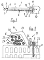
- FIG. 1 shows a first exemplary embodiment of the fastening element according to the invention, which is designated by the reference number 1. It includes a tubular one Shaft 2, which is provided with a through hole 3. At its the setting direction Rear end 4 facing away is the shaft 2 with a flange-like collar 5 equipped, which preferably has a plate spring-like elasticity. On his opposite front end 6, the shaft has 2 cutting edges 7, which are for one scraping or chiseling removal of the edge zone of a created drilling are trained.
- the shaft 2 has an axial slot 8, which extends over its stretches entire length. In the area of the cutting edges 7, the longitudinal slot 8 tapers and can be closed, for example, by a welding spot.
- the Outside diameter d of the shaft 2 at the rear end 4 is larger than at opposite front end 6.
- the longitudinal slot 8 has in the area of rear end 4 of the shaft 2 on the inner wall of the through hole 3 measured width w which is about 25% to about 50% of the outside diameter d of the shaft 2 in this area.
- the collar 5 having the rear end 4 of the shaft 2 of the fastener is in contact with a shoulder 11 on the drilling tool 9 and is supported on the shoulder 11 during operation so that axial blows delivered by the handheld device onto the fastening element 1 are transferable.
- the drilling tool 9 has a drill head 12, which with the 7 cut front end 6 of the shaft by a few millimeters, for example about 5 mm to 10 mm.
- the largest diameter of the drill head 12 is slightly smaller than the inside diameter of the through hole 3 am Front end 6 of the shaft 2.
- the drill head 12 rushes the cutting edges 7 at the front end 6 of the shank 2 ahead of the above-mentioned supernatant and creates a locating hole whose Diameter corresponds to the largest diameter of the drill head 12.
- the rear end 4 of the shaft 2 transmitted axial strokes in synchronism with the Creation of the location hole driven into the subsurface.
- the outer diameter of the shaft 2 has an oversize at the front end 6 the diameter of the location hole.
- the cutting edges 7 wear Front end 6 of the shaft 2 when driving in the fastener 1, the edge zone the receiving hole is chipped or chiseled off.
- the diameter of such calibrated mounting hole corresponds essentially to that Outside diameter of the shaft 2 on the cutting edges 7. Since the Outside diameter of the shaft 2 towards the rear end 4 of the shaft enlarged, the fastener 1 is when driving against the spring force of its material radially compressed and clamped in the Anchoring hole anchored. This shortly after the start of the axial Driving force effective clamping force leads to a decoupling of the usual rotary drilling tool 9 and the fastener 1.
- the fastening element 1 has at the rear end section 13 of the shaft Load application means 14. These can be, for example, an internal thread, holes in the Sheath of the shaft 2, tabs protruding from the collar or the like.
- Embodiment of the fastener according to the invention include the Load application means 14 a foot part 22 and a protruding from the foot part 22, in essential arcuate mounting bracket 23.
- the foot part 22 is a bore 24 for the shaft 2 provided.
- a countersink 25 on the top 26 of the foot part 22 serves as an abutment for the plate spring-like collar 5 at the rear end 4 of Shaft 2.
- a joint 28 is formed at the free end region 27 of the approximately opposite the foot part arcuate receiving bracket 23, a joint 28 is formed.
- the free one End section 29 of the mounting bracket 23 projects into the mounting bracket 23 limited receiving space 30.
- the End section can be pivoted away from the underground U into the receiving space.
- the foot part and the mounting bracket are preferably injection molded from plastic.
- the joint 28 can in this case simply be designed as a film hinge. The illustration shows this, particularly suitable for electrical mounting fastener in the Underground U anchored state with inserted cables K. As an example for a brittle underground U a hollow hole brick is shown.
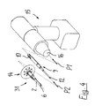
- the fastening element 31 shown in FIG. 3 is, for example, for fastening of insulation panels or wall cladding.
- the load application means 14 comprise a large-area head part 32 with a shaft part 33 protruding therefrom
- the head part 32 and the shaft part 33 are of an abutment for the rear Section 13 of the shaft 2 of the recess 34 having the fastening element 1 enforced.
- the abutment is formed by a shoulder 35 which is inside the Recess 34 is arranged and from the large-area head part 32 opposite free end 36 of the shaft part 33 a distance a of about 8 mm up to about 25 mm.
- the means of load application 14 have a mushroom shape overall. Load application means 14 designed in this way are the subject of EP-A-0 492 230 or the corresponding ones US-A-5,171,118.
- the shaft 2 of the fastening element 1 is through the continuous recess 34 guided and is supported with its plate spring collar 5 on the shoulder 35.
- the bore section extending from the shoulder 35 to the free end 36 of the shaft part 33 39 of the recess 34 has a diameter that is slightly smaller than the outer diameter of the shaft 2 in the rear section. This serves the bore section 39 as a guide for the shaft 2 of the fastening element 1.
- FIG. 4 an assembly unit is shown which allows, for example, a Insulation plate according to the direct assembly method according to the invention on a Fasten brick wall.
- the assembly unit includes a fastener 31, as shown in FIG. 3, a drilling tool 9 and a hand-held device 15 Hand tool 15 is, for example, a rotary drilling machine with Axial impact support.
- Drilling tool 9 with its insertion end 10 into the tool holder 16 of the Handheld device 15 inserted.
- the fastener 31 on the Drilling tool 9 pushed until the drill head 12 from the front end 6 of the Shaft 2 of the fastener 31 protrudes.
- the arrows P1 and P2 illustrate in the Representation of the assembly of the drilling tool 9 and the fastener 31.
- Die Assembly unit prepared in this way consisting of the handheld device 15, the Drilling tool 9 and the fastener 31 is made of the material Insulation plate pressed against the surface.
- the drilling tool 9 begins to create a locating hole in the underground.
- the front end 6 of the shank 2 of the fastening element 31 that carries the cutting edges touching the ground this follows the drilling head 12, supported by axial impacts in the underground. In this way, drilling is carried out continuously and at the same time Shaft 2 of the fastener 31 driven into the ground.
- the longitudinally slotted shaft 2 has an excess compared to the receiving bore, he is therefore compressed radially when driving in.
- the hollow shaft 2 of the Fastening element 31 forms a radial guide for the drilling tool 9. Which on the abutment supporting shaft 2 pulls that when driving into the ground Load application means 14 in the material of the insulation plate until the large-area head part, preferably flush against the surface of the plate.
- a fastener 31 is shown in FIG. 3, which is partially in the Material of an insulation plate P has been drawn in and not yet completely Underground U, for example a hollow hole brick, is anchored. It is clear It can be seen that the drill head 12 of the drilling tool 9 has the front end 6 of the shaft 2 towered over. This is only immediately before the following front end 6 of Fastening element 31 creates the receiving bore A.
- the flexible segments 38 are pressed into the interior of the recess 34 by the drilling tool 9.
- drilling tool 9 can have a circumferential groove 17 be provided which when pulling out the drilling tool 9 from the Fastener 31 comes into engagement with the flexible segments and these pulls out of the recess 34 again. In this way protrude after assembly the segments back to the center and can be used as a base for a subsequent applied plaster layer serve.
Landscapes
- General Engineering & Computer Science (AREA)
- Engineering & Computer Science (AREA)
- Mechanical Engineering (AREA)
- Processing Of Stones Or Stones Resemblance Materials (AREA)
- Joining Of Building Structures In Genera (AREA)
- Drilling And Boring (AREA)
- Earth Drilling (AREA)
- Drilling Tools (AREA)
- Percussive Tools And Related Accessories (AREA)
- Silver Salt Photography Or Processing Solution Therefor (AREA)
- Absorbent Articles And Supports Therefor (AREA)
- Auxiliary Devices For And Details Of Packaging Control (AREA)
- Paper (AREA)
- Diaphragms For Electromechanical Transducers (AREA)
- Liquid Developers In Electrophotography (AREA)
- Sheet Holders (AREA)
- Mutual Connection Of Rods And Tubes (AREA)
- Dowels (AREA)
- Slide Fasteners, Snap Fasteners, And Hook Fasteners (AREA)
- Gripping On Spindles (AREA)
Applications Claiming Priority (3)
| Application Number | Priority Date | Filing Date | Title |
|---|---|---|---|
| DE19620955A DE19620955A1 (de) | 1996-05-24 | 1996-05-24 | Befestigungssystem und Verfahren zur Erstellung von Befestigungen |
| DE19620955 | 1996-05-24 | ||
| PCT/EP1997/002386 WO1997045646A1 (de) | 1996-05-24 | 1997-05-09 | Befestigungselement und verfahren zu seiner verankerung |
Publications (2)
| Publication Number | Publication Date |
|---|---|
| EP0843788A1 EP0843788A1 (de) | 1998-05-27 |
| EP0843788B1 true EP0843788B1 (de) | 2001-04-04 |
Family
ID=7795219
Family Applications (2)
| Application Number | Title | Priority Date | Filing Date |
|---|---|---|---|
| EP97923041A Expired - Lifetime EP0843788B1 (de) | 1996-05-24 | 1997-05-09 | Befestigungselement und verfahren zu seiner verankerung |
| EP97810298A Expired - Lifetime EP0808696B1 (de) | 1996-05-24 | 1997-05-14 | Befestigungssystem und Verfahren zur Erstellung von Befestigungen |
Family Applications After (1)
| Application Number | Title | Priority Date | Filing Date |
|---|---|---|---|
| EP97810298A Expired - Lifetime EP0808696B1 (de) | 1996-05-24 | 1997-05-14 | Befestigungssystem und Verfahren zur Erstellung von Befestigungen |
Country Status (13)
| Country | Link |
|---|---|
| US (2) | US5899647A (hu) |
| EP (2) | EP0843788B1 (hu) |
| JP (2) | JPH11509920A (hu) |
| AT (2) | ATE200341T1 (hu) |
| AU (2) | AU731418B2 (hu) |
| CA (2) | CA2225146C (hu) |
| CZ (1) | CZ293151B6 (hu) |
| DE (3) | DE19620955A1 (hu) |
| DK (1) | DK0843788T3 (hu) |
| ES (2) | ES2155687T3 (hu) |
| HU (2) | HU221525B (hu) |
| PL (2) | PL186361B1 (hu) |
| WO (1) | WO1997045646A1 (hu) |
Cited By (1)
| Publication number | Priority date | Publication date | Assignee | Title |
|---|---|---|---|---|
| FR2992878A1 (fr) * | 2012-07-09 | 2014-01-10 | Lr Etanco Atel | Gabarit de percage. |
Families Citing this family (9)
| Publication number | Priority date | Publication date | Assignee | Title |
|---|---|---|---|---|
| US6488163B1 (en) * | 1999-10-01 | 2002-12-03 | Trn Business Trust | Knuckle coupler pin |
| DE10060484A1 (de) * | 2000-12-06 | 2002-06-13 | Fischer Artur Werke Gmbh | Werkzeug zum Bohren eines Bohrlochs und zum Setzen eines rohrförmigen Isolierplattendübels und Isolierplattendübel zum Setzen mit dem Werkzeug |
| DE10063816A1 (de) * | 2000-12-21 | 2002-06-27 | Fischer Artur Werke Gmbh | Werkzeug zum Bohren eines Bohrlochs und zum Setzen eines Isolierplattendübels |
| DE10117200A1 (de) * | 2001-04-06 | 2002-10-10 | Fischer Artur Werke Gmbh | Werkzeug und Verfahren zum Bohren eines Bohrlochs und zum Setzen einer Spannhülse in das Bohrloch in einem Arbeitsgang |
| JP4036756B2 (ja) † | 2001-04-26 | 2008-01-23 | “アールバーク”・トウンネーラウスバーウ・ゲゼルシヤフト・エム・ベー・ハー | 孔を開けてその孔に支持体を固定する方法および装置 |
| GB0315548D0 (en) * | 2003-07-03 | 2003-08-06 | Plasplugs Ltd | Wall plug |
| US20050207861A1 (en) * | 2004-03-22 | 2005-09-22 | Leatherman Barth A | Anchoring device |
| US20070044291A1 (en) * | 2005-08-23 | 2007-03-01 | Paul Gertner | System and method for precisely matching a predrilling tool with an insert for insertion into a substrate |
| DE102011006018A1 (de) * | 2011-03-24 | 2012-09-27 | Hilti Aktiengesellschaft | Befestigungssystem |
Family Cites Families (28)
| Publication number | Priority date | Publication date | Assignee | Title |
|---|---|---|---|---|
| US1429033A (en) * | 1922-01-07 | 1922-09-12 | William M Parker | Railway-rail fastening |
| US2240425A (en) * | 1939-07-31 | 1941-04-29 | Sternbergh James Hervey | Fastener |
| FR934263A (fr) * | 1946-09-18 | 1948-05-18 | Cheville murale et son mode d'utilisation | |
| BE656476A (hu) * | 1964-11-30 | 1965-03-16 | ||
| SE416997B (sv) * | 1979-02-09 | 1981-02-16 | Ingvar Sundberg | Expanderande fostanordning |
| US4395174A (en) * | 1981-05-18 | 1983-07-26 | Freeman James D | Self-penetrating fastener for fastening roofing panels to metal beams |
| US4507817A (en) * | 1981-10-08 | 1985-04-02 | Staffeld Stanley E | Connector and insertion tool |
| US4544041A (en) * | 1983-10-25 | 1985-10-01 | Rinaldi Roger E | Well casing inserting and well bore drilling method and means |
| US4617692A (en) * | 1983-12-30 | 1986-10-21 | Emhart Corporation | Tool for drilling and securing screw anchor to a wall |
| DE3535262A1 (de) * | 1985-10-03 | 1987-04-09 | Upat Max Langensiepen Kg | Spreizanker |
| US4720224A (en) * | 1986-05-29 | 1988-01-19 | United Industries Corporation | Sleeve anchor |
| US4750571A (en) * | 1986-10-08 | 1988-06-14 | Geeting Marvin D | Screen placement method and apparatus |
| US5066181A (en) * | 1987-01-21 | 1991-11-19 | Stadler Ag | Attachment element with large washer |
| GB2209489B (en) * | 1987-09-08 | 1991-05-22 | Itw Ltd | Fastening assembly |
| US4878794A (en) * | 1988-03-15 | 1989-11-07 | John W. Hall, Jr. | Collated screw fasteners |
| DE3914512A1 (de) * | 1989-05-02 | 1990-11-08 | Fischer Artur Werke Gmbh | Einschlagvorrichtung fuer einschlaganker mit spreizhuelse |
| US4966511A (en) * | 1989-06-14 | 1990-10-30 | Lee Yuan Ho | Expansion bolt unit for repeated use |
| US4990042A (en) * | 1989-09-05 | 1991-02-05 | Szayer Geza J | Self-drilling blind setting rivet |
| DE4003373C1 (hu) * | 1990-02-05 | 1991-05-08 | Sfs Stadler Holding Ag, Heerbrugg, Ch | |
| CH681648A5 (hu) * | 1990-06-25 | 1993-04-30 | Ver Drahtwerke Ag | |
| DE4041819A1 (de) * | 1990-12-24 | 1992-06-25 | Hilti Ag | Befestigungselement fuer isolationsplatten |
| FR2682725B1 (fr) * | 1991-10-16 | 1995-02-24 | Prospection & Inventions | Cheville pour fixation d'une piece a une paroi support de faible epaisseur. |
| US5536121A (en) * | 1992-09-22 | 1996-07-16 | Titan Technologies, Inc. | Anchor insert |
| DE4407349A1 (de) * | 1994-03-05 | 1995-09-07 | Toge Duebel A Gerhard Gmbh | Befestigungs-Vorrichtung |
| US5456326A (en) * | 1994-04-18 | 1995-10-10 | Exxon Production Research Company | Apparatus and method for installing open-ended tubular members axially into the earth |
| DE4432201A1 (de) * | 1994-09-09 | 1996-03-14 | Toge Duebel A Gerhard Gmbh | Isolierdorn-Dübel |
| DE4432780A1 (de) * | 1994-09-15 | 1996-03-21 | Hilti Ag | Rohr- und Kabelschelle mit Fußteil und Aufnahmebügel |
| US5743690A (en) * | 1995-01-03 | 1998-04-28 | Royle; Ian A. | Self-locking tubular fastener and fastener system |
-
1996
- 1996-05-24 DE DE19620955A patent/DE19620955A1/de not_active Withdrawn
-
1997
- 1997-01-31 CZ CZ1997288A patent/CZ293151B6/cs not_active IP Right Cessation
- 1997-05-09 WO PCT/EP1997/002386 patent/WO1997045646A1/de active IP Right Grant
- 1997-05-09 ES ES97923041T patent/ES2155687T3/es not_active Expired - Lifetime
- 1997-05-09 AT AT97923041T patent/ATE200341T1/de active
- 1997-05-09 US US08/983,402 patent/US5899647A/en not_active Expired - Lifetime
- 1997-05-09 PL PL97324633A patent/PL186361B1/pl not_active IP Right Cessation
- 1997-05-09 DE DE59703286T patent/DE59703286D1/de not_active Expired - Lifetime
- 1997-05-09 HU HU9902011A patent/HU221525B/hu not_active IP Right Cessation
- 1997-05-09 EP EP97923041A patent/EP0843788B1/de not_active Expired - Lifetime
- 1997-05-09 CA CA002225146A patent/CA2225146C/en not_active Expired - Fee Related
- 1997-05-09 DK DK97923041T patent/DK0843788T3/da active
- 1997-05-09 JP JP9541464A patent/JPH11509920A/ja not_active Ceased
- 1997-05-09 AU AU28952/97A patent/AU731418B2/en not_active Ceased
- 1997-05-09 CA CA002204957A patent/CA2204957C/en not_active Expired - Fee Related
- 1997-05-14 AT AT97810298T patent/ATE198060T1/de active
- 1997-05-14 DE DE59702749T patent/DE59702749D1/de not_active Expired - Lifetime
- 1997-05-14 EP EP97810298A patent/EP0808696B1/de not_active Expired - Lifetime
- 1997-05-14 AU AU21400/97A patent/AU712457B2/en not_active Ceased
- 1997-05-14 ES ES97810298T patent/ES2153173T3/es not_active Expired - Lifetime
- 1997-05-22 PL PL97320128A patent/PL184647B1/pl unknown
- 1997-05-23 US US08/862,529 patent/US5836405A/en not_active Expired - Lifetime
- 1997-05-23 HU HU9700943A patent/HU219555B/hu not_active IP Right Cessation
- 1997-05-26 JP JP13479697A patent/JP3973731B2/ja not_active Expired - Lifetime
Cited By (2)
| Publication number | Priority date | Publication date | Assignee | Title |
|---|---|---|---|---|
| FR2992878A1 (fr) * | 2012-07-09 | 2014-01-10 | Lr Etanco Atel | Gabarit de percage. |
| EP2684629A1 (fr) * | 2012-07-09 | 2014-01-15 | Ateliers LR Etanco | Gabarit de perçage |
Also Published As
Similar Documents
| Publication | Publication Date | Title |
|---|---|---|
| EP2752533B1 (de) | Vorrichtung zum Eintreiben eines Spreizelements in einen Dübel. | |
| EP0878261B1 (de) | Bohrwerkzeug | |
| EP0843788B1 (de) | Befestigungselement und verfahren zu seiner verankerung | |
| EP2044270B1 (de) | Befestigungssysteme und verfahren zur montage von dämmstoffplatten | |
| EP2265413B1 (de) | Werkzeug mit einer vorschubbewegungs- und/oder drehmoment-übertragungseinrichtung | |
| DE10159632B4 (de) | Dübel und Verfahren zur Montage von Dämmstoffplatten sowie eine Vorrichtung zum Eintreiben eines Spreizelements in einen Dübel | |
| EP0375606B1 (de) | Befestigungselement | |
| EP0988427B1 (de) | Verbindungselement zum verbinden von wenigstens zwei holzbauteilen und einer knotenplatte | |
| EP2487374B1 (de) | Verfahren und System zum Setzen eines selbstschneidenden Hinterschnittankers | |
| DE19520130A1 (de) | Formschlüssig setzbarer Hinterschnitt-Anker | |
| DE3524284C2 (de) | Befestigungsvorrichtung | |
| EP2502707B1 (de) | Befestigungssystem | |
| DE3633628A1 (de) | Verankerungselement, insbesondere duebel | |
| EP1400704A1 (de) | Einrichtung zur distanzierten Befestigung von Wärmedämmplatten an Wänden oder Decken | |
| EP1417418A1 (de) | Isolierplattendübel | |
| DE10213490A1 (de) | Verfahren und Vorrichtung zur Montage von Dämmstoffplatten | |
| DE3803708A1 (de) | Montagevorrichtung fuer schlagbohrmaschinen | |
| DE20320553U1 (de) | Einrichtung zur distanzierten Befestigung von Wärmedämmplatten an Wänden oder Decken | |
| AT410579B (de) | Bohrschraube und werkzeug zum einbohren | |
| EP0392201A2 (de) | Einschlagwerkzeug für Einschlaganker | |
| DE202007015716U1 (de) | Impulsnagel-Dübel | |
| DE8507867U1 (de) | Dübel zum Eintreiben in Leichtbeton od. dgl. | |
| DE19622543B4 (de) | Hinterschnittanker | |
| EP0412257A2 (de) | Spreizdübel | |
| EP2466158A1 (de) | Verfahren zum Setzen von mehrfach geschlitzten und mit einem Innengewinde versehenen Metalldübeln |
Legal Events
| Date | Code | Title | Description |
|---|---|---|---|
| PUAI | Public reference made under article 153(3) epc to a published international application that has entered the european phase |
Free format text: ORIGINAL CODE: 0009012 |
|
| AK | Designated contracting states |
Kind code of ref document: A1 Designated state(s): AT BE CH DE DK ES FR GB IE IT LI NL SE |
|
| 17P | Request for examination filed |
Effective date: 19980604 |
|
| 17Q | First examination report despatched |
Effective date: 19990818 |
|
| GRAG | Despatch of communication of intention to grant |
Free format text: ORIGINAL CODE: EPIDOS AGRA |
|
| GRAG | Despatch of communication of intention to grant |
Free format text: ORIGINAL CODE: EPIDOS AGRA |
|
| GRAH | Despatch of communication of intention to grant a patent |
Free format text: ORIGINAL CODE: EPIDOS IGRA |
|
| GRAH | Despatch of communication of intention to grant a patent |
Free format text: ORIGINAL CODE: EPIDOS IGRA |
|
| GRAA | (expected) grant |
Free format text: ORIGINAL CODE: 0009210 |
|
| ITF | It: translation for a ep patent filed |
Owner name: BARZANO' E ZANARDO MILANO S.P.A. |
|
| AK | Designated contracting states |
Kind code of ref document: B1 Designated state(s): AT BE CH DE DK ES FR GB IE IT LI NL SE |
|
| REF | Corresponds to: |
Ref document number: 200341 Country of ref document: AT Date of ref document: 20010415 Kind code of ref document: T |
|
| REG | Reference to a national code |
Ref country code: CH Ref legal event code: EP |
|
| REG | Reference to a national code |
Ref country code: IE Ref legal event code: FG4D Free format text: GERMAN |
|
| REF | Corresponds to: |
Ref document number: 59703286 Country of ref document: DE Date of ref document: 20010510 |
|
| REG | Reference to a national code |
Ref country code: ES Ref legal event code: FG2A Ref document number: 2155687 Country of ref document: ES Kind code of ref document: T3 |
|
| REG | Reference to a national code |
Ref country code: DK Ref legal event code: T3 |
|
| GBT | Gb: translation of ep patent filed (gb section 77(6)(a)/1977) |
Effective date: 20010614 |
|
| ET | Fr: translation filed | ||
| REG | Reference to a national code |
Ref country code: GB Ref legal event code: IF02 |
|
| PLBE | No opposition filed within time limit |
Free format text: ORIGINAL CODE: 0009261 |
|
| STAA | Information on the status of an ep patent application or granted ep patent |
Free format text: STATUS: NO OPPOSITION FILED WITHIN TIME LIMIT |
|
| 26N | No opposition filed | ||
| PGFP | Annual fee paid to national office [announced via postgrant information from national office to epo] |
Ref country code: IE Payment date: 20020529 Year of fee payment: 6 |
|
| PG25 | Lapsed in a contracting state [announced via postgrant information from national office to epo] |
Ref country code: IE Free format text: LAPSE BECAUSE OF NON-PAYMENT OF DUE FEES Effective date: 20030509 |
|
| REG | Reference to a national code |
Ref country code: IE Ref legal event code: MM4A |
|
| PGFP | Annual fee paid to national office [announced via postgrant information from national office to epo] |
Ref country code: NL Payment date: 20050503 Year of fee payment: 9 |
|
| PGFP | Annual fee paid to national office [announced via postgrant information from national office to epo] |
Ref country code: SE Payment date: 20050506 Year of fee payment: 9 |
|
| PGFP | Annual fee paid to national office [announced via postgrant information from national office to epo] |
Ref country code: DK Payment date: 20050513 Year of fee payment: 9 |
|
| PGFP | Annual fee paid to national office [announced via postgrant information from national office to epo] |
Ref country code: CH Payment date: 20050517 Year of fee payment: 9 |
|
| PGFP | Annual fee paid to national office [announced via postgrant information from national office to epo] |
Ref country code: BE Payment date: 20050715 Year of fee payment: 9 |
|
| PG25 | Lapsed in a contracting state [announced via postgrant information from national office to epo] |
Ref country code: SE Free format text: LAPSE BECAUSE OF NON-PAYMENT OF DUE FEES Effective date: 20060510 |
|
| PG25 | Lapsed in a contracting state [announced via postgrant information from national office to epo] |
Ref country code: LI Free format text: LAPSE BECAUSE OF NON-PAYMENT OF DUE FEES Effective date: 20060531 Ref country code: DK Free format text: LAPSE BECAUSE OF NON-PAYMENT OF DUE FEES Effective date: 20060531 Ref country code: CH Free format text: LAPSE BECAUSE OF NON-PAYMENT OF DUE FEES Effective date: 20060531 Ref country code: BE Free format text: LAPSE BECAUSE OF NON-PAYMENT OF DUE FEES Effective date: 20060531 |
|
| PGFP | Annual fee paid to national office [announced via postgrant information from national office to epo] |
Ref country code: IT Payment date: 20060531 Year of fee payment: 10 |
|
| PG25 | Lapsed in a contracting state [announced via postgrant information from national office to epo] |
Ref country code: NL Free format text: LAPSE BECAUSE OF NON-PAYMENT OF DUE FEES Effective date: 20061201 |
|
| REG | Reference to a national code |
Ref country code: CH Ref legal event code: PL Ref country code: DK Ref legal event code: EBP |
|
| EUG | Se: european patent has lapsed | ||
| NLV4 | Nl: lapsed or anulled due to non-payment of the annual fee |
Effective date: 20061201 |
|
| BERE | Be: lapsed |
Owner name: *HILTI A.G. Effective date: 20060531 |
|
| PG25 | Lapsed in a contracting state [announced via postgrant information from national office to epo] |
Ref country code: IT Free format text: LAPSE BECAUSE OF NON-PAYMENT OF DUE FEES Effective date: 20070509 |
|
| REG | Reference to a national code |
Ref country code: FR Ref legal event code: PLFP Year of fee payment: 20 |
|
| PGFP | Annual fee paid to national office [announced via postgrant information from national office to epo] |
Ref country code: GB Payment date: 20160504 Year of fee payment: 20 Ref country code: ES Payment date: 20160414 Year of fee payment: 20 Ref country code: DE Payment date: 20160504 Year of fee payment: 20 |
|
| PGFP | Annual fee paid to national office [announced via postgrant information from national office to epo] |
Ref country code: FR Payment date: 20160412 Year of fee payment: 20 Ref country code: AT Payment date: 20160425 Year of fee payment: 20 |
|
| REG | Reference to a national code |
Ref country code: DE Ref legal event code: R071 Ref document number: 59703286 Country of ref document: DE |
|
| REG | Reference to a national code |
Ref country code: GB Ref legal event code: PE20 Expiry date: 20170508 |
|
| REG | Reference to a national code |
Ref country code: AT Ref legal event code: MK07 Ref document number: 200341 Country of ref document: AT Kind code of ref document: T Effective date: 20170509 |
|
| PG25 | Lapsed in a contracting state [announced via postgrant information from national office to epo] |
Ref country code: GB Free format text: LAPSE BECAUSE OF EXPIRATION OF PROTECTION Effective date: 20170508 |
|
| REG | Reference to a national code |
Ref country code: ES Ref legal event code: FD2A Effective date: 20170825 |
|
| PG25 | Lapsed in a contracting state [announced via postgrant information from national office to epo] |
Ref country code: ES Free format text: LAPSE BECAUSE OF EXPIRATION OF PROTECTION Effective date: 20170510 |