EP0834652B1 - Glühkerze, ihr herstellunsverfahren und ionenstromdetektor - Google Patents
Glühkerze, ihr herstellunsverfahren und ionenstromdetektor Download PDFInfo
- Publication number
- EP0834652B1 EP0834652B1 EP97915709A EP97915709A EP0834652B1 EP 0834652 B1 EP0834652 B1 EP 0834652B1 EP 97915709 A EP97915709 A EP 97915709A EP 97915709 A EP97915709 A EP 97915709A EP 0834652 B1 EP0834652 B1 EP 0834652B1
- Authority
- EP
- European Patent Office
- Prior art keywords
- ion current
- current detecting
- detecting electrode
- glow plug
- heating
- Prior art date
- Legal status (The legal status is an assumption and is not a legal conclusion. Google has not performed a legal analysis and makes no representation as to the accuracy of the status listed.)
- Expired - Lifetime
Links
- 238000004519 manufacturing process Methods 0.000 title description 39
- 239000012212 insulator Substances 0.000 claims abstract description 223
- 238000002485 combustion reaction Methods 0.000 claims abstract description 209
- 239000000446 fuel Substances 0.000 claims abstract description 100
- 238000010438 heat treatment Methods 0.000 claims description 347
- 238000001514 detection method Methods 0.000 claims description 141
- 239000000919 ceramic Substances 0.000 claims description 82
- 229910010293 ceramic material Inorganic materials 0.000 claims description 59
- 239000000203 mixture Substances 0.000 claims description 39
- 239000002245 particle Substances 0.000 claims description 12
- 150000002500 ions Chemical class 0.000 abstract description 634
- 238000010276 construction Methods 0.000 abstract description 5
- OKTJSMMVPCPJKN-UHFFFAOYSA-N Carbon Chemical compound [C] OKTJSMMVPCPJKN-UHFFFAOYSA-N 0.000 description 89
- 229910052799 carbon Inorganic materials 0.000 description 89
- 239000000843 powder Substances 0.000 description 84
- 239000000758 substrate Substances 0.000 description 64
- 238000000034 method Methods 0.000 description 58
- 230000006870 function Effects 0.000 description 48
- 230000009471 action Effects 0.000 description 44
- 238000007639 printing Methods 0.000 description 42
- 229910052581 Si3N4 Inorganic materials 0.000 description 39
- HQVNEWCFYHHQES-UHFFFAOYSA-N silicon nitride Chemical compound N12[Si]34N5[Si]62N3[Si]51N64 HQVNEWCFYHHQES-UHFFFAOYSA-N 0.000 description 39
- 239000000463 material Substances 0.000 description 38
- YXTPWUNVHCYOSP-UHFFFAOYSA-N bis($l^{2}-silanylidene)molybdenum Chemical compound [Si]=[Mo]=[Si] YXTPWUNVHCYOSP-UHFFFAOYSA-N 0.000 description 37
- 229910021344 molybdenum silicide Inorganic materials 0.000 description 36
- 238000002347 injection Methods 0.000 description 33
- 239000007924 injection Substances 0.000 description 33
- WABPQHHGFIMREM-UHFFFAOYSA-N lead(0) Chemical compound [Pb] WABPQHHGFIMREM-UHFFFAOYSA-N 0.000 description 32
- 238000012545 processing Methods 0.000 description 32
- 238000009413 insulation Methods 0.000 description 28
- 230000003647 oxidation Effects 0.000 description 21
- 238000007254 oxidation reaction Methods 0.000 description 21
- 230000035939 shock Effects 0.000 description 21
- 239000013078 crystal Substances 0.000 description 19
- 229910052751 metal Inorganic materials 0.000 description 19
- 239000002184 metal Substances 0.000 description 19
- 238000005245 sintering Methods 0.000 description 19
- 230000006378 damage Effects 0.000 description 16
- 238000002156 mixing Methods 0.000 description 15
- 230000015572 biosynthetic process Effects 0.000 description 14
- 238000010586 diagram Methods 0.000 description 13
- 230000008569 process Effects 0.000 description 13
- 239000003870 refractory metal Substances 0.000 description 13
- 239000004020 conductor Substances 0.000 description 12
- 230000000694 effects Effects 0.000 description 12
- 238000010304 firing Methods 0.000 description 12
- 239000007787 solid Substances 0.000 description 12
- 230000035882 stress Effects 0.000 description 12
- 229910045601 alloy Inorganic materials 0.000 description 11
- 239000000956 alloy Substances 0.000 description 11
- 239000012535 impurity Substances 0.000 description 11
- 238000000465 moulding Methods 0.000 description 11
- BASFCYQUMIYNBI-UHFFFAOYSA-N platinum Chemical compound [Pt] BASFCYQUMIYNBI-UHFFFAOYSA-N 0.000 description 11
- 238000007650 screen-printing Methods 0.000 description 11
- PXHVJJICTQNCMI-UHFFFAOYSA-N Nickel Chemical compound [Ni] PXHVJJICTQNCMI-UHFFFAOYSA-N 0.000 description 10
- 230000008859 change Effects 0.000 description 10
- 238000002844 melting Methods 0.000 description 10
- 230000008018 melting Effects 0.000 description 10
- 230000009467 reduction Effects 0.000 description 10
- 229910000510 noble metal Inorganic materials 0.000 description 9
- 239000011347 resin Substances 0.000 description 9
- 229920005989 resin Polymers 0.000 description 9
- XLYOFNOQVPJJNP-UHFFFAOYSA-N water Substances O XLYOFNOQVPJJNP-UHFFFAOYSA-N 0.000 description 9
- PNEYBMLMFCGWSK-UHFFFAOYSA-N aluminium oxide Inorganic materials [O-2].[O-2].[O-2].[Al+3].[Al+3] PNEYBMLMFCGWSK-UHFFFAOYSA-N 0.000 description 8
- 239000011230 binding agent Substances 0.000 description 8
- 229910052593 corundum Inorganic materials 0.000 description 8
- 230000006872 improvement Effects 0.000 description 8
- 229910052721 tungsten Inorganic materials 0.000 description 8
- 229910001845 yogo sapphire Inorganic materials 0.000 description 8
- 239000011248 coating agent Substances 0.000 description 7
- 238000000576 coating method Methods 0.000 description 7
- 229910052759 nickel Inorganic materials 0.000 description 7
- 150000004767 nitrides Chemical class 0.000 description 7
- 229910052697 platinum Inorganic materials 0.000 description 7
- 229910021332 silicide Inorganic materials 0.000 description 7
- FVBUAEGBCNSCDD-UHFFFAOYSA-N silicide(4-) Chemical compound [Si-4] FVBUAEGBCNSCDD-UHFFFAOYSA-N 0.000 description 7
- 229910052750 molybdenum Inorganic materials 0.000 description 6
- 238000007649 pad printing Methods 0.000 description 6
- 229910052761 rare earth metal Inorganic materials 0.000 description 6
- 230000003746 surface roughness Effects 0.000 description 6
- 229910052719 titanium Inorganic materials 0.000 description 6
- 239000010936 titanium Substances 0.000 description 6
- 239000000567 combustion gas Substances 0.000 description 5
- 238000004891 communication Methods 0.000 description 5
- 238000007906 compression Methods 0.000 description 5
- 238000011161 development Methods 0.000 description 5
- 238000003754 machining Methods 0.000 description 5
- VYPSYNLAJGMNEJ-UHFFFAOYSA-N Silicium dioxide Chemical compound O=[Si]=O VYPSYNLAJGMNEJ-UHFFFAOYSA-N 0.000 description 4
- ATJFFYVFTNAWJD-UHFFFAOYSA-N Tin Chemical compound [Sn] ATJFFYVFTNAWJD-UHFFFAOYSA-N 0.000 description 4
- 230000006835 compression Effects 0.000 description 4
- 230000007797 corrosion Effects 0.000 description 4
- 238000005260 corrosion Methods 0.000 description 4
- 230000001747 exhibiting effect Effects 0.000 description 4
- 239000007789 gas Substances 0.000 description 4
- 239000011521 glass Substances 0.000 description 4
- 238000001746 injection moulding Methods 0.000 description 4
- 229910052741 iridium Inorganic materials 0.000 description 4
- 230000004048 modification Effects 0.000 description 4
- 238000012986 modification Methods 0.000 description 4
- 238000002360 preparation method Methods 0.000 description 4
- 230000001737 promoting effect Effects 0.000 description 4
- 230000004044 response Effects 0.000 description 4
- 229910052703 rhodium Inorganic materials 0.000 description 4
- 229910052707 ruthenium Inorganic materials 0.000 description 4
- 239000004065 semiconductor Substances 0.000 description 4
- WFKWXMTUELFFGS-UHFFFAOYSA-N tungsten Chemical compound [W] WFKWXMTUELFFGS-UHFFFAOYSA-N 0.000 description 4
- PQZSQOYXZGDGQW-UHFFFAOYSA-N [W].[Pb] Chemical compound [W].[Pb] PQZSQOYXZGDGQW-UHFFFAOYSA-N 0.000 description 3
- 230000001154 acute effect Effects 0.000 description 3
- 230000006866 deterioration Effects 0.000 description 3
- 238000010292 electrical insulation Methods 0.000 description 3
- 239000002737 fuel gas Substances 0.000 description 3
- PCHJSUWPFVWCPO-UHFFFAOYSA-N gold Chemical compound [Au] PCHJSUWPFVWCPO-UHFFFAOYSA-N 0.000 description 3
- 229910052737 gold Inorganic materials 0.000 description 3
- 239000010931 gold Substances 0.000 description 3
- 239000012774 insulation material Substances 0.000 description 3
- 238000012544 monitoring process Methods 0.000 description 3
- 229910052763 palladium Inorganic materials 0.000 description 3
- 239000012188 paraffin wax Substances 0.000 description 3
- 239000002994 raw material Substances 0.000 description 3
- 230000000717 retained effect Effects 0.000 description 3
- 239000010937 tungsten Substances 0.000 description 3
- 229910052720 vanadium Inorganic materials 0.000 description 3
- LEONUFNNVUYDNQ-UHFFFAOYSA-N vanadium atom Chemical compound [V] LEONUFNNVUYDNQ-UHFFFAOYSA-N 0.000 description 3
- 238000004804 winding Methods 0.000 description 3
- 241001247986 Calotropis procera Species 0.000 description 2
- 230000002159 abnormal effect Effects 0.000 description 2
- 239000003990 capacitor Substances 0.000 description 2
- 150000001875 compounds Chemical class 0.000 description 2
- 229910052802 copper Inorganic materials 0.000 description 2
- 238000005520 cutting process Methods 0.000 description 2
- 230000007423 decrease Effects 0.000 description 2
- 230000003247 decreasing effect Effects 0.000 description 2
- 238000005238 degreasing Methods 0.000 description 2
- 230000004907 flux Effects 0.000 description 2
- 239000003502 gasoline Substances 0.000 description 2
- 238000000227 grinding Methods 0.000 description 2
- 238000010030 laminating Methods 0.000 description 2
- 239000007769 metal material Substances 0.000 description 2
- 150000002739 metals Chemical class 0.000 description 2
- 229910001120 nichrome Inorganic materials 0.000 description 2
- 230000001105 regulatory effect Effects 0.000 description 2
- 230000004043 responsiveness Effects 0.000 description 2
- 230000000630 rising effect Effects 0.000 description 2
- 238000005096 rolling process Methods 0.000 description 2
- 239000000377 silicon dioxide Substances 0.000 description 2
- 239000000243 solution Substances 0.000 description 2
- 230000002123 temporal effect Effects 0.000 description 2
- 230000008646 thermal stress Effects 0.000 description 2
- VYZAMTAEIAYCRO-UHFFFAOYSA-N Chromium Chemical compound [Cr] VYZAMTAEIAYCRO-UHFFFAOYSA-N 0.000 description 1
- ZOKXTWBITQBERF-UHFFFAOYSA-N Molybdenum Chemical compound [Mo] ZOKXTWBITQBERF-UHFFFAOYSA-N 0.000 description 1
- 229910052779 Neodymium Inorganic materials 0.000 description 1
- 229910002795 Si–Al–O–N Inorganic materials 0.000 description 1
- 229910000831 Steel Inorganic materials 0.000 description 1
- RTAQQCXQSZGOHL-UHFFFAOYSA-N Titanium Chemical compound [Ti] RTAQQCXQSZGOHL-UHFFFAOYSA-N 0.000 description 1
- QCWXUUIWCKQGHC-UHFFFAOYSA-N Zirconium Chemical compound [Zr] QCWXUUIWCKQGHC-UHFFFAOYSA-N 0.000 description 1
- 239000000853 adhesive Substances 0.000 description 1
- 230000001070 adhesive effect Effects 0.000 description 1
- 230000002411 adverse Effects 0.000 description 1
- 230000001476 alcoholic effect Effects 0.000 description 1
- 239000010953 base metal Substances 0.000 description 1
- 239000003054 catalyst Substances 0.000 description 1
- 238000006243 chemical reaction Methods 0.000 description 1
- 229910052681 coesite Inorganic materials 0.000 description 1
- 238000007796 conventional method Methods 0.000 description 1
- 239000000498 cooling water Substances 0.000 description 1
- 229910052906 cristobalite Inorganic materials 0.000 description 1
- 238000002425 crystallisation Methods 0.000 description 1
- 230000008025 crystallization Effects 0.000 description 1
- 230000001419 dependent effect Effects 0.000 description 1
- 238000003745 diagnosis Methods 0.000 description 1
- 230000005684 electric field Effects 0.000 description 1
- 239000007772 electrode material Substances 0.000 description 1
- 230000008030 elimination Effects 0.000 description 1
- 238000003379 elimination reaction Methods 0.000 description 1
- 230000007613 environmental effect Effects 0.000 description 1
- 238000001704 evaporation Methods 0.000 description 1
- 230000008020 evaporation Effects 0.000 description 1
- 239000000295 fuel oil Substances 0.000 description 1
- 238000009499 grossing Methods 0.000 description 1
- 229910052735 hafnium Inorganic materials 0.000 description 1
- VBJZVLUMGGDVMO-UHFFFAOYSA-N hafnium atom Chemical compound [Hf] VBJZVLUMGGDVMO-UHFFFAOYSA-N 0.000 description 1
- 238000005304 joining Methods 0.000 description 1
- 229910052746 lanthanum Inorganic materials 0.000 description 1
- FZLIPJUXYLNCLC-UHFFFAOYSA-N lanthanum atom Chemical compound [La] FZLIPJUXYLNCLC-UHFFFAOYSA-N 0.000 description 1
- MRELNEQAGSRDBK-UHFFFAOYSA-N lanthanum oxide Inorganic materials [O-2].[O-2].[O-2].[La+3].[La+3] MRELNEQAGSRDBK-UHFFFAOYSA-N 0.000 description 1
- 239000010687 lubricating oil Substances 0.000 description 1
- 239000002075 main ingredient Substances 0.000 description 1
- 230000013011 mating Effects 0.000 description 1
- 238000005259 measurement Methods 0.000 description 1
- 230000007246 mechanism Effects 0.000 description 1
- 239000011733 molybdenum Substances 0.000 description 1
- QEFYFXOXNSNQGX-UHFFFAOYSA-N neodymium atom Chemical compound [Nd] QEFYFXOXNSNQGX-UHFFFAOYSA-N 0.000 description 1
- 239000012811 non-conductive material Substances 0.000 description 1
- 229910052762 osmium Inorganic materials 0.000 description 1
- TWNQGVIAIRXVLR-UHFFFAOYSA-N oxo(oxoalumanyloxy)alumane Chemical compound O=[Al]O[Al]=O TWNQGVIAIRXVLR-UHFFFAOYSA-N 0.000 description 1
- KTUFCUMIWABKDW-UHFFFAOYSA-N oxo(oxolanthaniooxy)lanthanum Chemical compound O=[La]O[La]=O KTUFCUMIWABKDW-UHFFFAOYSA-N 0.000 description 1
- 238000012805 post-processing Methods 0.000 description 1
- 238000000926 separation method Methods 0.000 description 1
- 235000012239 silicon dioxide Nutrition 0.000 description 1
- 239000004071 soot Substances 0.000 description 1
- 239000007921 spray Substances 0.000 description 1
- 238000005507 spraying Methods 0.000 description 1
- 239000010959 steel Substances 0.000 description 1
- 229910052682 stishovite Inorganic materials 0.000 description 1
- 229910052905 tridymite Inorganic materials 0.000 description 1
- 239000002699 waste material Substances 0.000 description 1
- FIXNOXLJNSSSLJ-UHFFFAOYSA-N ytterbium(III) oxide Inorganic materials O=[Yb]O[Yb]=O FIXNOXLJNSSSLJ-UHFFFAOYSA-N 0.000 description 1
- 229910052727 yttrium Inorganic materials 0.000 description 1
- VWQVUPCCIRVNHF-UHFFFAOYSA-N yttrium atom Chemical compound [Y] VWQVUPCCIRVNHF-UHFFFAOYSA-N 0.000 description 1
- 229910052726 zirconium Inorganic materials 0.000 description 1
Images


Classifications
-
- F—MECHANICAL ENGINEERING; LIGHTING; HEATING; WEAPONS; BLASTING
- F23—COMBUSTION APPARATUS; COMBUSTION PROCESSES
- F23Q—IGNITION; EXTINGUISHING-DEVICES
- F23Q7/00—Incandescent ignition; Igniters using electrically-produced heat, e.g. lighters for cigarettes; Electrically-heated glowing plugs
- F23Q7/001—Glowing plugs for internal-combustion engines
-
- F—MECHANICAL ENGINEERING; LIGHTING; HEATING; WEAPONS; BLASTING
- F02—COMBUSTION ENGINES; HOT-GAS OR COMBUSTION-PRODUCT ENGINE PLANTS
- F02P—IGNITION, OTHER THAN COMPRESSION IGNITION, FOR INTERNAL-COMBUSTION ENGINES; TESTING OF IGNITION TIMING IN COMPRESSION-IGNITION ENGINES
- F02P17/00—Testing of ignition installations, e.g. in combination with adjusting; Testing of ignition timing in compression-ignition engines
- F02P17/12—Testing characteristics of the spark, ignition voltage or current
-
- F—MECHANICAL ENGINEERING; LIGHTING; HEATING; WEAPONS; BLASTING
- F02—COMBUSTION ENGINES; HOT-GAS OR COMBUSTION-PRODUCT ENGINE PLANTS
- F02P—IGNITION, OTHER THAN COMPRESSION IGNITION, FOR INTERNAL-COMBUSTION ENGINES; TESTING OF IGNITION TIMING IN COMPRESSION-IGNITION ENGINES
- F02P19/00—Incandescent ignition, e.g. during starting of internal combustion engines; Combination of incandescent and spark ignition
- F02P19/02—Incandescent ignition, e.g. during starting of internal combustion engines; Combination of incandescent and spark ignition electric, e.g. layout of circuits of apparatus having glowing plugs
- F02P19/028—Incandescent ignition, e.g. during starting of internal combustion engines; Combination of incandescent and spark ignition electric, e.g. layout of circuits of apparatus having glowing plugs the glow plug being combined with or used as a sensor
-
- F—MECHANICAL ENGINEERING; LIGHTING; HEATING; WEAPONS; BLASTING
- F02—COMBUSTION ENGINES; HOT-GAS OR COMBUSTION-PRODUCT ENGINE PLANTS
- F02P—IGNITION, OTHER THAN COMPRESSION IGNITION, FOR INTERNAL-COMBUSTION ENGINES; TESTING OF IGNITION TIMING IN COMPRESSION-IGNITION ENGINES
- F02P17/00—Testing of ignition installations, e.g. in combination with adjusting; Testing of ignition timing in compression-ignition engines
- F02P17/12—Testing characteristics of the spark, ignition voltage or current
- F02P2017/125—Measuring ionisation of combustion gas, e.g. by using ignition circuits
-
- F—MECHANICAL ENGINEERING; LIGHTING; HEATING; WEAPONS; BLASTING
- F23—COMBUSTION APPARATUS; COMBUSTION PROCESSES
- F23N—REGULATING OR CONTROLLING COMBUSTION
- F23N2227/00—Ignition or checking
- F23N2227/42—Ceramic glow ignition
-
- F—MECHANICAL ENGINEERING; LIGHTING; HEATING; WEAPONS; BLASTING
- F23—COMBUSTION APPARATUS; COMBUSTION PROCESSES
- F23N—REGULATING OR CONTROLLING COMBUSTION
- F23N5/00—Systems for controlling combustion
- F23N5/02—Systems for controlling combustion using devices responsive to thermal changes or to thermal expansion of a medium
- F23N5/12—Systems for controlling combustion using devices responsive to thermal changes or to thermal expansion of a medium using ionisation-sensitive elements, i.e. flame rods
-
- F—MECHANICAL ENGINEERING; LIGHTING; HEATING; WEAPONS; BLASTING
- F23—COMBUSTION APPARATUS; COMBUSTION PROCESSES
- F23Q—IGNITION; EXTINGUISHING-DEVICES
- F23Q7/00—Incandescent ignition; Igniters using electrically-produced heat, e.g. lighters for cigarettes; Electrically-heated glowing plugs
- F23Q7/001—Glowing plugs for internal-combustion engines
- F23Q2007/002—Glowing plugs for internal-combustion engines with sensing means
-
- F—MECHANICAL ENGINEERING; LIGHTING; HEATING; WEAPONS; BLASTING
- F23—COMBUSTION APPARATUS; COMBUSTION PROCESSES
- F23Q—IGNITION; EXTINGUISHING-DEVICES
- F23Q7/00—Incandescent ignition; Igniters using electrically-produced heat, e.g. lighters for cigarettes; Electrically-heated glowing plugs
- F23Q7/001—Glowing plugs for internal-combustion engines
- F23Q2007/004—Manufacturing or assembling methods
Definitions
- the present invention relates to a glow plug for promoting ignition and combustion of fuel and an ion current detector using the glow plug.
- JP-A No. 7-259597 discloses a method for detecting ion current (ionization degree of fuel gases) due to combustion of fuel by a sleeve-like electrode attached to a mounting seat for a fuel injection nozzle, the sleeve-like electrode electrically insulated from the injection nozzle and a cylinder head of the engine, and connected to an external detection circuit.
- US Patent No. 4,739,731 discloses a sensor provided with a ceramic glow plug for detecting ion current (conductivity of ionized fuel gases).
- ion current conductivity of ionized fuel gases.
- an electric conductive layer made of platinum is formed on a surface of a heater (heating element) of the ceramic glow plug, and electrically insulated from a combustion chamber and a glow plug clamping fixture.
- An external power source for 250-volt DC voltage
- ion current detectors with a glow plug having such an ion current detecting function ignition and combustion of fuel are generally promoted by a heating action of the heating element when the engine starts at low temperature.
- a heating state of the heating element usually continues after warm-up of the engine has been completed until the combustion is stabilized (generally, referred to as "afterglow"). After completion of the afterglow, the heating action of the glow plug is stopped and the processing step of detecting ion current is started.
- ion current detectors display only a heating action and cannot detect ion current during the afterglow period. Since in this period any result of ion current detection can not be used for performing combustion control, the combustion cannot be controlled optimally. Stated more specifically, it is difficult to control the combustion optimally during the afterglow period because such a result of ion current detection cannot be used in individual combustion operations, e.g., for performing feedback control of ignition stage and flame failure detection.
- the ion current detecting electrode supported at the tip of the glow plug directly touches a flame having a high temperature, stresses tend to be concentrated in the neighborhood of the ion current detecting electrode and could damage the ceramic glow plug such as to crack it.
- Document JP-A-59-160046 discloses an ignition timing detector arranged in a cylinder head in the manner that it is projected into a combustion chamber having an injection nozzle.
- the ignition timing detector is obtained by covering the outside of an ionic-current detecting core with an insulator and winding a nichrome wire serving as a heating member for a glow plug in the form of a coil around the insulator.
- One end of the nichrome wire is connected to a center electrode while the other end is connected to a cover.
- the timing when fuel injected into the combustion chamber is fired is detected from the ionic current passed between the core and the outer wall, and the actual combustion time is calculated in a control circuit from the ionic current and the output of a crank angle position detector.
- the ignition timing sensor is incorporated with an electric resistance heating member at the tip end of the flame sensor thereof to use it both for a preheating plug in combination.
- the flame sensor section of the ignition timing sensor is provided with the electric resistance heating member, in which a high resistance wire member of tungsten or the like is wound around the tip end of a guide member in the shape of a coil and is incorporated into a casing. Both ends of the guide member are connected to an electric source through a connector and a switch while the flame sensor section functions as the preheating plug.
- Document JP-A-2-176322 discloses a conductive heater with a means which serves as an ignition source for fuel and a flame detecting means which determines the change of the current level relative to the applied voltage and the presence of flame.
- the flame detecting device monitoring command Prior to the igniter ignition command, the flame detecting device monitoring command is sent out so as to diagnose the insulation deterioration condition of a conductive heater in advance, and the diagnosis made is indicated on a first indicator with a lamp.
- the current and voltage are applied to the conductive heater to bring same to the red-hot condition at 1,000 to 1,200 deg.C, which serves as the ignition source.
- the fuel valve opening command is sent out.
- Document DE 37 06555 A1 discloses a structure wherein an ion current detecting electrode is arranged in a glow plug of filament type and of sheath type.
- the filament type structure is just formed in such a manner that a hearing element is wound in the form of a coil around the periphery of a ceramic cylinder.
- An insulated ion electrode is arranged at the ceramic cylinder. All of the ion electrodes are made of a metal.
- Document EP 0 456 245 A2 discloses a structure wherein a heating element made of tungsten exhibiting positive-temperature-coefficient is provided such that a combustion state is monitored by reading the variation in resistance value of the heating element caused heat by the combustion flame. When monitoring combustion, a predetermined amount of current is applied to the heating element, thereby detecting a state of voltage drop due to increase in resistance caused by the increase in temperature.
- Another object of the present invention is to provide an ion current detector capable of detecting ion current precisely even for a period of glow of the glow plug and hence maintaining proper combustion of fuel based on the detection results.
- Still another object of present invention is to provide an ion current detector capable of detecting ion current precisely and hence performing precise control of individual processings such as ignition stage detection and flame failure detection based on the detection results.
- Yet another object of the present invention is to provide a relatively inexpensive glow plug having excellent durability, which can detect ion current precisely without any trouble from carbon adhesion and any damage to the ion current detector.
- Yet another object of the present invention is to provide a glow plug having excellent durability without suffering any damage such as a crack and showing ease of manufacture.
- ion current means current passing through ionized fuel gases in a combustion chamber.
- the ion current detecting electrode may be referred to as the ion current detecting electrode.
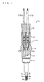
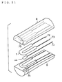
- a glow plug according to the invention as claimed in claim 1 comprises an insulator made of an insulating ceramic, a heating element made of a conductive ceramic and embedded in the insulator and energized through a pair of lead wires to generate heat, a combination of said insulator and said heating element being sintered as a single unit; and a ion current detecting electrode embedded in said insulator with a portion of said ion current detecting electrode exposed to a flame produced in a combustion chamber so that a ionization state in the flame can be detected.
- the heating element of the glow plug acts to promote ignition and combustion of fuel in the combustion chamber by a heating action of the heating element.
- the ion current detecting electrode embedded in the heat resisting insulator detects the ionization state in the combustion flame.
- the ion current detecting electrode and the inner wall of the combustion chamber adjacent to the ion current detecting electrode form two electrodes for capturing positive and negative ions existing therebetween during fuel combustion.
- the glow plug the ion current can be detected precisely with very simple structure, and information detected can be effectively used for combustion control. Further, since the glow plug is given an ion current detecting function, an inexpensive ion sensor can be provided.
- the glow plug of the invention is constructed such that the majority of the ion current detecting electrode is embedded in the heat resisting insulator except only a portion exposed to the outside, an amount of carbon adhered to the outer surface of the glow plug cannot establish an electric connection between the electrode and a housing (grounded side) to cause error detection of the ion current that may occur in the prior art (USP 4,739,731).
- the exposed portion of the ion current detecting electrode is preferably provided at the tip of the glow plug so that the exposed portion and the housing (inner wall side of the combustion chamber) will be separated as far from each other as possible.
- the glow plug can maintain its performance in detecting ion current for long periods.
- the heating element itself is embedded inside the heat resisting insulator, it never change its heating characteristics due to lowering of resistance or the like to maintain high heating performance for long periods. In other words, since such a construction could resist oxidation to wear the heating element, the sectional area is kept constant and the resistance does not vary. The construction also avoids damaging the heating element under thermal action such as thermal shock in the combustion chamber.
- the heating element and the ion current detecting element is constructed as follows.
- the invention as claimed in claim 2 recites that the heating element and the ion current detecting electrode is electrically connected to each other.
- the heating element and the ion current detecting electrode are integrally formed, while in the invention as claimed in claim 4 lead wires reside between the heating element and the ion current detecting electrode.
- both the heating performance of the heating element and the performance in detecting ion current can be maintained for long periods as mentioned above. From the standpoint of the manufacturing process, it is considered that the invention as claimed in claim 3 shows the simplest way to manufacture the glow plug.
- the glow plug as claimed in claim 5 is such that the heating element and the ion current detecting electrode are insulated from each other. Since the heating element and the ion current detecting electrode are energized through individual paths, the ion current detecting electrode can detect ion current synchronously with the heating action of the heating element (i.e., the combustion condition can be grasped constantly).
- the invention as claimed in claim 6 recites that at least the portion of the ion current detecting electrode exposed to the flame is made of a conductive ceramic material. It is therefore possible to minimize oxidation wearing of the ion current detecting electrode even when it is exposed to hot combustion gases, and hence to further improve the durability of the performance in detecting ion current by the glow plug.
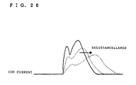
- the invention as claimed in claim 7 recites that the heating element and the ion current detecting electrode are produced dividedly from each other by using mixtures having different components or different particle sizes. Such divided production can change the resistance between the heating element and the ion current detecting electrode to provide a glow plug (ion current sensor) according to the application.
- a glow plug ion current sensor
- the result of ion current detection is used for flame failure detection, only the present or absence of ion current is required for the determination.
- an ion current detector as claimed in claim 8 features that the adhered carbon is removed without stopping the ion current detection by using the glow plug of claim 5 that can carry out the ion current detection by the ion current detecting electrode simultaneously with the heating action of the heating element.
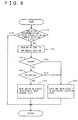
- the ion current detector comprises switching means for turning on or off the power supply to the heating element, leakage current detection means for detecting a leakage current flowing from the ion current detecting electrode in a predetermined stage before fuel combustion, and operation means for operating the switching means to temporarily energize the heating element when the leakage current detected is larger than a predetermined threshold.
- the exposed portion of the ion current detecting electrode and the housing side are electrically conducted to reduce the insulation resistance. Consequently, a leakage current flows and a desired ion current waveform cannot be obtained.
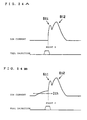
- the leakage current flows before its ion current waveform is obtained (before point A in Figs. 24A and 24B).
- the carbon adhered state of the outer surface of the glow plug is estimated based on the leakage current, and if it is such a carbon adhered state, the adhered carbon will be burnt off by running the heating element hot.
- a desired waveform of ion current e.g., the waveform shown in Fig. 24A
- the detection result can be used for precise processings such as ignition stage detection and flame failure detection.
- the insulation resistance between the ion current detecting electrode and the housing side depends on the pressure in the combustion chamber.
- the timing period of the pressure rise corresponds to the compression stage in a Diesel engine, for example.
- the leakage current may also be detected in correspondence to the timing period of fuel injection into the combustion chamber.
- the timing period of fuel injection corresponds to a period that elapses between the moment the pressure in the combustion chamber of the Diesel engine rises and the moment just before the fuel burns. It is therefore possible to detect the leakage current more securely under such a condition that the carbon adhered.
- the heating element and the ion current detecting electrode are first produced, surrounded with the heat resisting insulator, and hot-pressed at a predetermined temperature. A portion of the heat resisting insulator is then cut to expose the ion current detecting electrode to the outside.
- the glow plug having such special structure can be made up without requiring any complicated process, thereby providing the glow plug having such an excellent ion current detecting function through the simple manufacturing method.
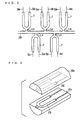
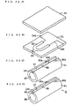
- the heating element and the ion current detecting electrode are provided on a thin-plate like heat resisting insulation sheet to be wrapped around a rod-shaped heat resisting insulation solid-shaft.
- the heat resisting insulation sheet and the heat resisting solid shaft are heat-treated, and a portion of the heat-treated body of the heat resisting insulation sheet and the heat resisting solid shaft is cut so that the ion current detecting electrode will be exposed to the outside.
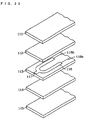
- the heating element and the ion current detecting electrode are provided on certain one of plural layer members. Then the plural layer members are so superposed that the layer member having the heating element and the ion current detecting electrode thereon will reside in a central portion. After that, the plural layer members put on top of each other are heat-treated, and a portion of superposed layer members is cut so that the ion current detecting electrode will be exposed to the outside.
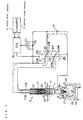
- a glow plug having a heating element energized through a pair of conductive wires to generate heat is used, and the following ion current detector is constructed by using an ion current detecting function of the glow plug.
- the conductive wire pair (lead wire pair) and the heating element are insulated from the grounded side such as a cylinder head.
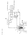
- An ion current detector includes switching means for switching over between a first state and a second state, in which the first state is for applying a supply voltage from a power source to the conductive wire pair, and the second state is for shutting the electric path between the conductive wire pair and the power source and applying the supply voltage between the heating element and a wall portion of a combustion chamber. Further, ion current detection means is provided for detecting ion current resulting from fuel combustion by using the voltage supplied from the power source in the second state.
- the supply voltage is applied from the power source to the conductive wire pair to run the heating element hot.
- This state corresponds to the state in which ignition and combustion of fuel is being promoted when the engine starts at low temperature.
- the electric path between the conductive wire pair and the power source is shut and the supply voltage is applied between the heating element and the wall portion of the combustion chamber.
- This state corresponds to the state in which ion current is detected. The ion current is detected by the ion current detection means.
- the voltage application to the heating element is performed through the common conductive wire pair in both states, and the switching between both states is selectively performed by the switching means. It is therefore possible to simplify the structure of the ion current detector that uses the glow plug having the ion current detecting function, such as wiring of the conductive wires connected to the heating element, and other circuit arrangements associated with ion current detection, and hence to provide an inexpensive ion current detector. In this case, the ion current detection accuracy is never reduced in spite of such simple structure.
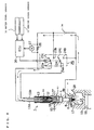
- the power source is connected through the switching means to an electric path between the heating element and the wall portion of the combustion chamber, while according to another example the power source is connected directly to the electric path between the heating element and the wall portion of the combustion chamber.
- the switching means can be materialized by a switching circuit with plural switch contacts, or a semiconductor switching element (transistor, thyristor or the like), with some resistance thereon.
- the power source for applying voltage to the conductive wire pair in the first state and the power source for applying voltage between the heating element and the wall portion of the combustion chamber in the second state may be provided separately, or a common power source may be used therebetween. In either case, the ion current can be detected precisely. In particular, according to the latter example a power source exclusively used for the ion current detection is not required, e.g., a power source other than the vehicle battery, thus simplifying the structure.
- one end of the power source is connected to one conductive wire coupled to the heating element while the other is connected to a cylinder head of the Diesel engine for holding the glow plug.
- the structure for applying voltage between the heating element and the wall portion of the combustion chamber can be simplified when it is used in the Diesel engine.
- a constant voltage circuit is provided between the power source and one wire of the conductive wire pair for regulating the supply voltage of the power source to a constant value. Since the ion current is originally weak, the ion current value detected is susceptible to variation of the applied voltage to cause a detection error when the applied voltage largely varies. The detection error also causes various problems. For example, when the output information of the ion current (wave height, area, etc.) is used for flame failure detection, the accuracy of the flame failure detection must be lowered. In contrast, the above structure permits the improvement in accuracy of the ion current detection and hence the improvement in accuracy of individual processings such as flame failure detection.
- a plurality of glow plugs are connected in parallel and power-supply paths to individual glow plugs are switched at the same time by the switching means.
- the switching circuit as the switching means and the detecting resistor as the ion current detection means can be shared by the glow plugs, thereby further simplifying the structure. For example, when the glow plugs are provided in the combustion chambers of a multiple cylinder engine, ion current can be detected for each cylinder in time series.
- the ion current detector can also be simplified with structure other than the above.
- an voltmeter for ion current detection is provided between one conductive wire of the glow plug and the ground contact.
- the voltmeter can be constructed by an amplifier measuring a potential difference from the ground with relatively simple structure, rather than by a differential amplifier having relatively complicated internal structure.
- a capacitor is provided between one conductive wire of the glow plug and the voltmeter.
- the DC component of the supply voltage is cut by the capacitor. Therefore, even when a power source of a relatively high voltage (e.g., 50 volts) is used exclusively for the ion current detection, the voltage applied to the voltage detector (amplifier) never exceeds the withstand voltage since the high voltage of the power source is not directly applied to the voltage detector. As a result, inconvenient things such as damage to the voltage detector can be prevented. It should be noted that this structure becomes more effective in the case the supply voltage for the ion current detection is 30 volts or higher.
- an ion current detecting resistor is provided on the grounded side of the power source for detecting ion current from a potential difference between both terminals of the ion current detecting resistor.
- the voltage waveform corresponding to the ion current waveform detected is plotted on a reference level of O volt. It is therefore unnecessary to use an expensive, complicated voltage detector even when using a supply voltage exceeding the withstand voltage of the voltage detector.
- Such structure is preferably materialized such that the heating-element power source and the ion current detecting power source are provided separately with the ion current detecting resistor provided on the grounded side of the latter power source. This is because the heating performance of the heating element may be lowered at heating time when the heating element and the ion current detecting resistor are connected in series.
- a glow plug can be used for the glow plug in the above ion current detector, in which a heating element portion having a heating element is so provided that it projects into the combustion chamber for burning fuel.
- An ion current detecting electrode to the inner wall of the combustion chamber is formed in the heating element.
- the heating element of the glow plug acts to promote ignition and combustion of fuel in the combustion chamber due to the heating action when the heating element is running hot.
- the heating element acts as the ion current detecting electrode for detecting the ion current resulting from the fuel combustion.
- the heating element and the inner wall of the combustion chamber adjacent to the heating element form two electrodes for capturing positive and negative ions existing therebetween when burning the fuel. It is therefore possible to detect the ion current precisely in spite of such simple structure, and hence to effectively use the information on the detected ion current for various combustion control. Further, since the ion current detecting function is given to the glow plug, an inexpensive ion current sensor can be provided.
- a further example of a glow plug comprises a heating element portion provided with a heat resisting insulator and a heating element embedded in the heat resisting insulator, in which a portion of the heating element is exposed from the heat resisting insulator and the exposed portion is used as an ion current detecting electrode to the inner wall of the combustion chamber.
- the exposed portion of the heating element effectively acts as the ion current detecting electrode, the following effect can be newly obtained.
- the adhered carbon is burnt off by the heating action of the heating element (e.g., due to glowing when the engine starts at low temperature).
- life of the glow plug is never reduced even in such structure in which an exposed portion is provided in the heating element for use as an ion current detecting electrode, so that the glow plug adds excellent durability that are useful for long periods.
- the heating element is preferably made of a ceramic material.
- the heating element made of a ceramic material is so arranged that a portion of the heating element will be exposed into the combustion chamber, oxidation wearing of the heating element can be minimized even when it is exposed to hot combustion gases, thereby further improving the durability of the glow plug.
- the heating-element running state of the glow plug and the ion current detecting state of the glow plug are switched (switching means).
- switching means In the ion current detecting state of the glow plug, combustion ions are captured between the glow plug electrode portion and the inner wall of the combustion chamber, and ion current is detected by current detection means such as an ion current detecting resistor.
- the switching means can be operated to temporarily switch over to the ion current detecting state at least immediately after the fuel ignition stage (operation means). Since the function of the glow plug for promoting ignition and combustion of fuel is given top priority in all the functions of the glow plug, for example, during the afterglow period when the engine starts at low temperature, the ion current detection has not been performed during the afterglow period in the prior art. In contrast, according to this example, the ion current detection period is temporarily provided within a range in which the heating function of the glow plug is never damaged even under the heating-element running state such as in the afterglow period. It is therefore possible to detect ion current precisely even in the glow period of the glow plug, and hence to maintain the fuel combustion properly using the result of the ion current detection.
- the operation means operates the switching means to switch over to the ion current detecting state for a predetermined period of time after each event of the fuel injection into the combustion chamber.
- the ion current detection period is set based on the fuel injection timing, the ion current can be detected securely by setting the ion current detection period as short as possible, thereby minimizing lowering of the glow function of the glow plug.
- the operation means operates at a predetermined frequency to switch over between the heating-element running state and the ion current detecting state. Even in such a case, the ion current detecting function and the heating-element running function can be united in the afterglow period.
- the glow plug comprises a heating element energized through a pair of lead wires to generate heat, a heat resisting insulator embedding the heating element therein, and an ion current detecting electrode integrally formed with the heating element.
- a glow plug is used to detect ion current produced when burning fuel.
- the ion current can be detected precisely in spite of such very simple structure, and the information on the ion current detected can be effectively used for combustion control.
- the heating-element running state of the glow plug and the ion current detecting state of the glow plug are switched (switching means).
- switching means switching means.
- the glow plug is switched from the heating-element running state to the ion current detecting state.
- combustion ions are captured between the exposed electrode portion of the glow plug and the inner wall of the combustion chamber, and the ion current is detected by the current detection means such as an ion current detecting resistor.
- a leakage current flowing from the exposed electrode portion is detected in a predetermined stage before fuel ignition under the ion current detecting state of the glow plug (leakage current detection means).
- the switching means is operated to temporarily switch over from the ion current detecting state to the heating-element running state (operation means).
- the carbon adhered to the outer portion of the glow plug in the combustion chamber can cause a reduction in insulation resistance between the exposed electrode and the grounded portion, and hence a flow of leakage current.
- a desired waveform of the ion current may not be obtained.
- the leakage current flows before a real waveform of the ion current is plotted (before point A in Fig. 6).
- the leakage current is detected in a predetermined stage (in the timing period of fuel injection in Fig. 6), so that the carbon adhesion to the outer glow plug can be estimated based on the leakage current.
- the glow plug is changed to the heating-element running state and the adhered carbon is burnt off. It is therefore possible to constantly detect a desired ion current waveform (e.g., the waveform shown in Fig. 24A), and hence to perform ignition detection or flame failure detection precisely using the detection result.
- a desired ion current waveform e.g., the waveform shown in Fig. 24A
- the insulation resistance between the exposed electrode and the grounded side depends on the pressure in the combustion chamber. For this reason, as the pressure rises, the insulation resistance is reduced and the leakage current tends to flow. To avoid such an inconvenient thing, the leakage current is detected when the pressure in the combustion chamber rises. In this case, the presence or absence of the leakage current can be detected securely.
- the pressure rise in the combustion chamber corresponds to the compression process in the Diesel engine.
- the leakage current is detected in response to the timing of fuel injection into the combustion chamber.
- the timing period of fuel injection corresponds to a period that elapses between the moment the pressure in the combustion chamber of the Diesel engine rises and the moment just before the fuel burns. It is therefore possible to detect the leakage current more securely under such a condition that the carbon adhered.
- the operation means holds the switching means in the heating-element running state for a period of time according to the leakage current value detected by the leakage current detection means.
- the leakage current value detected by the leakage current detection means.
- a high-pass filter is provided to the signal output portion of the ion current detector for detecting ion current, and the detection signal is input to the signal processor. Since the high-pass filter is incorporated in the system circuitry, the ion current due to combustion can be separated from the leakage current due to a failure of insulation even when the carbon adheres to the ion current detecting electrode of the glow plug, thereby detecting the ion current securely. If the combustion condition information such as ignition stage is judged from the output waveform of the high-pass filter, the judgment processing becomes easy to perform. A study confirms that the cut-off frequency of the high-pass filter is preferably set from 50 Hz to 5 kHz, more preferably 100 to 500 Hz.
- the threshold for use in judging leakage current by the operation means is set to a value near the acceptable maximum value.
- the threshold for use in judging leakage current should be set small.
- the use of the above structure permits separation between the leakage current and the ion current even when some leakage current flows. If the threshold for use in judging leakage current is set large within the acceptable range, the number of times the adhered carbon is burnt off will be reduced. It is therefore possible to detect ion current frequently, and hence to detect the combustion conditions frequently.
- Another example comprises comparison means for inputting an output signal of the high-pass filter and comparing the input signal with the threshold for use in detecting combustion conditions. Since the output of the high-pass filter is compared with the threshold for use in detecting combustion conditions, the processing for detecting combustion conditions can be easily carried out.
- the conductive heating-element and the ion current detecting electrode are provided inside the insulator.
- At least the exposed portion contacting the flame is constructed of the above conductive mixed-sinter with adding a sintering auxiliary made of more than one kind of oxide of rare-earth element.
- the structure of the mixed sinter is composed of a first crystal phase and a grain boundary phase between the first crystal phases. Portion of the grain boundary phase or the entire grain boundary phase is crystallized into a second crystal phase containing the sintering auxiliary.
- the ion current detecting electrode is thus composed of the first crystal phase as a crystal phase of either the conductive ceramic material or the nonconductive ceramic material or both, and the grain boundary phase between the crystal phases.
- the portion of the grain boundary phase or the entire grain boundary phase is crystallized into the second crystal phase while the grain boundary phase in the conventional or typical conductive mixed-sinter are made into glass phase in whole.
- the conductive heating-element and the ion current detecting electrode are provided in the insulator in either way that molded parts of them are produced separately, embedded in the ceramic powder material for the insulator and molded integrally, or that the molded parts of the conductive heating-element and the ion current detecting electrode are inserted between two molded parts of insulator produced in advance.
- the molded parts of the insulator, the conductive heating-element and the ion current detecting electrode are made up such that main composition of ceramic powders for the molded parts is mixed with paraffin wax and other resin and the mixture is injection-molded.
- the ion current detecting electrode is produced of a mixed material that contains a sintering auxiliary made of an oxide or oxides of rare-earth element in addition to the conductive ceramic powder and the nonconductive ceramic powder.
- the mixed sinter made of such a material is composed of the first crystal phase and the grain boundary phase between the first crystal phases, with portion of the grain boundary phase or the entire grain boundary phase crystallized into the second crystal phase.
- the conductive heating-element and the insulator it is also preferable to use such a material that contains a sintering auxiliary made of an oxide or oxides of rare-earth element in addition to the conductive ceramic powder and the nonconductive ceramic powder.
- the conductive heating-element and the insulator can thus be made in excellent structure with portion of the grain boundary phase or the entire grain boundary phase crystallized into the second crystal phase.
- the glow plug is run hot by the current passing therethrough to promote ignition and combustion of fuel in the combustion chamber, while the ion current detecting electrode form two electrodes with the inner wall of the combustion chamber adjacent to the ion current detecting electrode to detect ion current in the combustion flame.
- the glow plug has the ion current detecting function in addition to the original heating function, it can be manufactured with compact structure and at low cost.
- the glow plug can detect ion current precisely for long periods.
- At least the exposed portion contacting the flame is constructed of the mixed sinter having the above structure.
- the structure of the mixed sinter is composed of the first crystal phase and the grain boundary phase between the first crystal phases, with portion of the grain boundary phase or the entire grain boundary phase crystallized into a second crystal phase containing the sintering auxiliary.
- the melting point of the grain boundary phase and the corrosion resistance can be improved more largely than the conventional structure composed of amorphous glass phases without the second crystal in each grain boundary phase. It is therefore possible to improve the performance of the ion current detecting electrode that could resist thermal shock, oxidation and corrosion, and hence to prevent any damage to the ion current detecting electrode, thereby improving reliability of the accuracy in detecting ion current and reliability of the glow plug.
- the glow plug is such that the conductive heating-element, the lead wires and ion current detecting electrode are integrally provided inside the insulator, the structure of the glow plug is simplified. It is therefore possible to detect ion current precisely without carbon adhesion and hence to provide a glow plug exhibiting excellent durability without any damage to the ion current detecting electrode.
- the content of the sintering auxiliary to the total weight of the conductive ceramic material and the nonconductive ceramic material in the ion current detecting electrode is preferably set in a range from 3 to 25 wt%. If less than 3 wt%, the mixed sinter can not improve its compactness and is difficult to form the second crystal phase in each grain boundary phase.
- the grain boundary phase is made into a glass phase without being crystallized. In this case, the melting point of the grain boundary phase is reduced to lower the resistance to thermal shock and corrosion.
- the second crystal phase of the ion current detecting electrode preferably exists in each grain boundary phase with a degree of crystallization of more than 5%. If less than 5%, the resistance to oxidation and corrosion can not be so improved since the melting point increases due to existence of the second crystal phase.
- the conductive ceramic material is preferably made of more than one kind of the materials such as metallic carbide, nitride and boride. In this case, the second crystal phase can be formed easily.
- the ion current detecting electrode provided in the glow plug according to a further example has an exposed portion exposed from the insulator into the flame.
- the exposed portion also has a ground portion with a surface roughness Rz of 0.1 to 30 ⁇ m (an average roughness of 10 points).
- the surface roughness Rz of the ground portion is an average roughness of 10 points determined under the provision of JIS B 0601, and the value is in a range of between 0.1 ⁇ m and 30 ⁇ m. If less than 0.1 ⁇ m, the ion current can not be detected sufficiently. If more than 30 ⁇ m, a crack or cracks may be developed due to thermal shock or the like.
- the ground portion is controlled within the above range by grinding it with a grindstone or the like. In this case, a desired surface roughness Rz is obtained by regulating the grain size of the abrasive of the grindstone and other grinding conditions.
- molded parts for the conductive heating-element and the ion current detecting electrode are previously produced, embedded in the ceramic powder material for the insulator and molded integrally.
- the conductive heating-element and the ion current detecting electrode may be inserted between two insulator parts separately produced.
- the above insulator molded parts or the molded body with the conductive heating-element and the ion current detecting electrode may be made up by an injection molding.
- the conductive heating-element and the ion current detecting electrode may also be provided inside the insulator by printing formation.
- the printing formation is performed such that two products (green sheets) of ceramic material, e.g., for forming the insulator, are prepared, and the conductive heating-element, the associated lead wires and the ion current detecting electrode are printed on the surface of one product with a conductive material in a desired form by a printing technique such as screen printing, pad printing or hot stamp.
- the other product is so stacked that it will cover the printed portion and then firing is performed.
- the conductive heating-element, the lead wires and the ion current detecting electrode may be printed on two or more products.
- the conductive heating-element and the ion current detecting electrode may also be printed on different products and laminated together.
- the insulator with the conductive heating-element, the lead wires and the ion current detecting electrode printed and built therein is thus obtained.
- the insulator is cut as required and the ground portion is ground in the exposed portion of the ion current detecting electrode in a manner described above.
- Such a glow plug as the ground portion of a specific surface roughness Rz is provided in the exposed portion of the ion current detecting electrode can thus be obtained.
- the glow plug having the above structure is operated to generate heat by passing current through the conductive heating-element so that ignition and combustion of fuel in the combustion chamber can be promoted by the heating action.
- the ion current detecting electrode forms two electrodes with the adjacent inner wall of the combustion chamber to detect an ionization state in the flame. It is therefore possible for the structure to detect ion current precisely and hence to effectively use the information for combustion control. Further, since the glow plug has the ion current detecting function in addition to the original heating function (glow function) in the combustion chamber, it can be manufactured with compact structure and at low cost.
- the ground portion is provided in the exposed portion of the ion current detecting electrode.
- the ground portion has a surface roughness Rz ranging from 0.1 to 30 ⁇ m. Since the ground portion has lots of micron size irregularities, electric flux in the electric field between the ion current detecting electrode and the adjacent cylinder head is concentrated to the convexities in the irregularities, and potential gradients become sharp in the neighborhood of the convexities to which the electric flux is concentrated. Such sharp potential gradients attract charged particles of combustion gases into the neighborhood of the convexities. Consequently, the ion current detecting electrode having the ground portion of the specific surface roughness Rz attracts the charged particles in the combustion chamber due to considerable force, thereby further improving the accuracy in detecting ion current.
- the conductive heating-element the lead wires and the ion current detecting electrode are integrally provided inside the insulator, the structure is simplified. It is therefore possible to detect ion current precisely without any trouble from carbon adhesion, and hence to provide a glow plug having excellent durability.
- the area of the exposed portion provided at the tip of the ion current detecting electrode is preferably set in a range from 1x10 -6 to 0.5 cm 2 .
- the ion current detecting electrode can detect ion output as long as the area (S) of the exposed portion of the ion current detecting electrode is larger than 0, if the area of the exposed portion is less than 1x10 -6 cm 2 , the dimensions of the exposed portion will be very small such as 10 ⁇ m x 10 ⁇ m or smaller when it is formed by a printing technique, resulting in decreased productivity. On the other hand, if larger than 0.5 cm 2 , the area occupied by the ion current detecting electrode will become too large and hence the conductive heating-element will be made small, resulting in decreased productivity.
- the ion current detecting electrode can be electrically connected to the conductive heating-element.
- the manufacturing process becomes simple.
- Another example is made to the glow plug in which the conductive heating-element, the lead wires and the ion current detecting electrode are provided inside the insulator. According to this example, at least top portion of the ion current detecting electrode is covered with a nonconductive porous layer.
- the nonconductive porous layer has a communication hole opening from the surface of ion current detecting electrode into the flame.
- the porous layer has electrical nonconductivity.
- the nonconductive porous layer is made up by sintering nonconductive ceramic powder containing a main component such as Si 3 N 4 , Al 2 O 3 or SiO 2 .
- the conductive heating-element and the ion current detecting electrode can be provided in the insulator in the following manner:
- the conductive heating-element and the ion current detecting electrode are previously produced while the insulator having grooves for accommodating them are prepared.
- the conductive heating-element and the ion current detecting electrode are then embedded in the grooves and integrally baked.
- the conductive heating-element, the ion current detecting electrode and the insulator may be made of ceramic powder.
- the glow plug having the above structure is operated to generate heat by passing current through the conductive heating-element so that ignition and combustion of fuel in the combustion chamber can be promoted by the heating action.
- the ion current detecting electrode forms two electrodes with the adjacent inner wall of the combustion chamber to detect an ionization state in the flame.
- the ion current detecting electrode Since the top portion of the ion current detecting electrode is covered with the nonconductive porous layer, the ion current detecting electrode is never exposed to the direct fire of the flame. For this reason, the ion current detecting electrode is not subjected to stress concentration due to thermal shock by the hot flame, and hence any damage such as crack development. Further, since the nonconductive porous layer has the communication hole, ions flow into a space between the ion current detecting electrode and the cylinder head through the communication hole, thereby detecting the ions accurately.
- the structure it is therefore possible for the structure to detection current precisely and hence to effectively use the information for combustion control. Further, since the glow plug has the ion current detecting function in addition to the original heating function (glow function), it can be manufactured with compact structure and at low cost.
- the conductive heating-element is embedded in the insulator, it is never corroded by the combustion flame, so that excellent durability and good heating performance can be displayed for long periods without any reduction in the resistance and changes in heating characteristic.
- the conductive heating-element could resist oxidation wearing, the sectional area is maintained constantly and the resistance is kept at a constant level. Further, the danger of occurrence of inconvenient things such as damage to the conductive heating-element due to a thermal action such as thermal shock in the combustion chamber can be avoided.
- the glow plug can detect ion current precisely for long periods.
- the conductive heating-element, the lead wires and the ion current detecting electrode are integrally provided inside the insulator, the structure is simplified. It is therefore possible to detect ion current precisely without any trouble from carbon adhesion, and hence to provide a glow plug having excellent durability and easy to manufacture.
- the thickness of the nonconductive porous layer is preferably between 0.2 mm and 1.5 mm. If less than 0.2 mm, damage such as crack development may be caused due to thermal shock by the flame. If more than 1.5 mm, the thickness will become too large and a crack or cracks may be developed due to stress concentration by the hot flame.
- the nonconductive porous layer and the insulator are preferably made of the same material. In this case, the junction between both is improved, and the resistance to thermal shock is also improved since both has the same coefficient of linear expansion.
- the ion current detecting electrode,and the conductive heating-element can be combined.
- the conductive heating-element is covered with the nonconductive porous layer at the tip of the glow plug main body.
- the ion current detecting electrode can be made of a conductive ceramic material containing MoSi 2 , WC, TiN or the like, or refractory metal such as W, Mo or Ti.
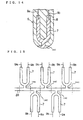
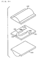
- the top portion of the insulator is preferably formed into a semi-spherical shape.
- the acute angle portion is removed from the tip of the insulator, the turbulence of combustion flame can be prevented in the neighborhood of the ion current detecting electrode to stabilize the detection performance. Further, since thermal stress concentration is prevented, the resistance to thermal shock can also be improved.
- the communication hole formed in the nonconductive porous layer can have any hole diameter as long as it is penetrated from the surface of the nonconductive porous layer to the surface of the ion current detecting electrode.
- the communication hole has only to pass current when the tip of the glow plug is immersed in an alcoholic solution containing water at a ratio of 50 to 50 and a voltage of 12 volt or so is applied between the tip and the solution.
- the glow plug is so constructed that the ion current detecting electrode will be electrically connected to the midway of the heating element, and that, when R1 denotes electric resistance of a first heating section of the heating element from a first end of the heating element, corresponding to a positive side in passing a DC current through the heating element, to a center of a first connecting portion, at which the ion current detecting electrode is first connected to the heating element; R2 denotes electric resistance of a second heating section of the heating element from the center of the first connecting portion, where a connection between the heating element and the ion current detecting electrode is first established, to a second end of the heating element corresponding to a negative side in passing a DC current through the heating element; and r denotes electric resistance between the first connecting portion and the opening end of the ion current detecting electrode, it will satisfy the relationship of R2 > r.
- the first connecting portion is a portion at which the ion current detecting electrode is first connected to the conductive heating-element in a path from the positive end to the negative end of the conductive heating-element.
- Such definition is made by taking into account both a single ion current detecting electrode and a plurality of ion current detecting electrodes provided for the conductive heating-element.
- the first heating section corresponds a path from the positive end to the closest ion current detecting electrode and the second heating section is a path from the negative end to the adjacent ion current detecting electrode.
- the second heating section may be connected to one or plural ion current detecting electrodes.
- both materials, or width, thickness or length of the conduction path can be changed.
- the second heating section and the ion current detecting electrode can be constructed at different mixing rates between the conductive ceramic powder and the nonconductive ceramic powder.
- a nonconductive ceramic material Si 3 N 4 , Al 2 O 3 , BN or the like is used.
- As a sintering auxiliary more than one kind of oxide of rare-earth element is added.
- MoSi 2 as a conductive ceramic material
- Si 3 N 4 as a nonconductive ceramic material
- Y 2 O 3 and Al 2 O 3 as a sintering auxiliary
- the conductive heating-element and the ion current detecting electrode is constructed by making the grain size of Si 3 N 4 larger than that of MoSi 2 so that conductive particles of MoSi 2 will be linked together around a nonconductive particle of Si 3 N 4 .
- MoSi 2 having a mean diameter of 1 ⁇ m and Si 3 N 4 having a mean diameter of 15 ⁇ m are used.
- the mean diameter is 1 ⁇ m as well.
- the sintering auxiliary of Y 2 O 3 and Al 2 O 3 is added at a total rate of 10 % per weight.
- more than one kind of oxide of rare-earth element other than Y 2 O 3 such as Yb 2 O 3 , La 2 O 3 or Nd 2 O, may be used.
- the mixture of the conductive ceramic material and the nonconductive ceramic material is used for the conductor, there may be used only the conductive ceramic material or a mixture of the nonconductive ceramic material and metal powder instead of the conductive ceramic material, or only metal powder or a metal wire is also possible.
- the insulator is made of a ceramic sinter that is constructed by adding a sintering auxiliary of Y 2 O 3 and Al 2 O 3 to the main composition of conductive ceramic MoSi 2 and nonconductive ceramic Si 3 N 4 .
- the insulator is constructed by making the grain size of Si 3 N 4 equal to or slightly smaller than that of MoSi 2 so that the conductive particles of MoSi 2 are surrounded with the nonconductive particles of Si 3 N 4 and divided into parts.
- MoSi 2 having a mean diameter of 0.9 ⁇ m and Si 3 N 4 having a mean diameter of 0.6 ⁇ m can be used.
- the sintering auxiliary more than one kind oxide of rare-earth element other than Y 2 O 3 , such as one combined with, yttrium, lanthanum and neodymium, may be used.
- the electric resistance R2 of the second heating section in a range of between 0.1 ⁇ and 5 ⁇ and the electric resistance r in a range of between 0.05 ⁇ and 2.5 ⁇ .
- a molded body for the conductive heating-element and the ion current detecting electrode is previously produced, embedded in the insulator and molded integrally.
- the lead wires are connected simultaneously with this molding process.
- Refractory metal or its alloy such as tungsten and molybdenum can be used for the lead wires.
- the molded body of the conductive heating-element and the ion current detecting electrode may be inserted between two insulator parts separately produced.
- the above insulator molded parts or the molded body with the conductive heating-element and the ion current detecting electrode may be made up such that main materials of ceramic powders are premixed with a binder of resin and the like, and the mixture is injection-molded. The molded parts are then baked.
- the conductive heating-element and the ion current detecting electrode may also be provided inside the insulator by printing formation.
- the printing formation is performed such that a product (green sheet) of ceramic material, e.g., for forming the insulator, are prepared, and the conductive heating-element, the associated lead wires and the ion current detecting electrode are printed on the surface of the product with a conductive material by a printing technique such as screen printing, pad printing or hot stamp. The product is then rolled and baked. The insulator with the conductive heating-element, the lead wires and the ion current detecting electrode printed and built therein is thus obtained.
- the firing of the injection-molded body or printed body is performed by a hot press method.
- the body is pressurized at 400 kg/cm 2 under one atmosphere of Ar gas and baked at a temperature of 1800 °C for 60 min.
- the glow plug is energized to generate heat by passing current therethrough so that ignition and combustion of fuel in the combustion chamber can be promoted by the heating action.
- the ion current detecting electrode forms two electrodes with the adjacent inner wall of the combustion chamber to detect an ionization state in the flame.
- the glow plug has the ion current detecting function in addition to the original heating function (glow function), it can be manufactured with compact structure and at low cost.
- the electric resistance R2 of the second heating section is set larger than the electric resistance r of the ion current detecting electrode. For this reason, when the carbon adhered to the surface of the insulator of the glow plug and caused an electrical short between the ion current detecting electrode and the cylinder head, the carbon between the ion current detecting electrode and the cylinder head can be burnt off securely by applying a DC current across the conductive heating-element.
- the DC current flows from the positive end to the cylinder head through the first heating section, the ion current detecting electrode and the adhered carbon since the relationship between the electric resistance R2 of the second heating section of the conductive heating-element and the electric resistance r of the ion current detecting electrode exhibits R2 > r.
- the carbon on the surface of the insulator is heated and burnt due to the heat by combination with the air in the combustion chamber. Since the carbon is thus burnt off, the electrical short due to carbon adhesion can be easily eliminated. It is therefore possible to detect ion current accurately for long periods.
- the conductive heating-element is embedded in the insulator, it is never corroded by the combustion flame, so that good heating performance can be displayed for long periods without any reduction in the resistance and changes in heating characteristic.
- the conductive heating-element could resist oxidation wearing, the sectional area is maintained constantly and the resistance is kept at a constant level. Further, the danger of occurrence of inconvenient things such as damage to the conductive heating-element due to a thermal action such as thermal shock in the combustion chamber can be avoided.
- the conductive heating-element, the lead wires and the ion current detecting electrode are provided inside the insulator, the structure is simplified. It is therefore possible to detect ion current precisely without any trouble from carbon adhesion, and hence to provide a glow plug having excellent durability.
- the electric resistance R2 of the second heating section is preferably set to more than twice the electric resistance r of the ion current detecting electrode as recited in claim 50. In this case, the carbon can be burnt off more securely.
- the ion current detecting electrode can be constructed of the main composition of a conductive ceramic material made of more than one kind of metallic silicide, carbide, nitride or boride, or a mixture of a conductive ceramic material and a nonconductive ceramic material.
- a conductive ceramic material made of more than one kind of metallic silicide, carbide, nitride or boride, or a mixture of a conductive ceramic material and a nonconductive ceramic material.
- the heat resistance can be improved and the expansion coefficient can be easily adjusted and matched with that of the insulator, so that the resistance to thermal shock can also be improved.
- the ion current detecting electrode can also be constructed of the main composition of a material made of one kind of refractory metal having a melting point of 1200 °C or higher, or a mixture of a refractory metal material and a nonconductive ceramic material.
- a material made of one kind of refractory metal having a melting point of 1200 °C or higher or a mixture of a refractory metal material and a nonconductive ceramic material.
- the metal material can be used in the form of wire, the cost associated with material preparation, machining and assembly can be reduced.
- the high-temperature resistance and the resistance to oxidation can be improved, and besides, the coefficient of linear expansion can be easily adjusted and matched with that of the insulator, so that excellent durability can be obtained.
- the conductive heating-element of the glow plug is energized to generate heat up to a temperature from 1000 to 1100 °C, the melting point must be set to 1200 °C by taking into account the heat resistance of the ion current detecting electrode.
- the exposed portion of the ion current detecting electrode exposed from the insulator preferably has a portion made of more than one kind of noble metal such as Pt, Ir, Rh, Ru and Pd. In this case, the resistance to wear and oxidation of the ion current detecting electrode can be improved.
- the ion current detecting electrode of the glow plug is electrically connected to the midway of the conductive heating-element.
- the tip of the ion current detecting electrode is exposed from the insulator into the flame, with positioning it more than 2 mm away from the tip of the housing supporting the main body for the insulator and the ion current detecting electrode.
- a molded body for the conductive heating-element and the ion current detecting electrode is previously produced, embedded in the ceramic powder material for the insulator and molded integrally.
- the conductive heating-element and the ion current detecting electrode may be inserted between two insulator parts separately produced.
- the above insulator molded parts or the molded body with the conductive heating-element and the ion current detecting electrode may be made up by an injection molding.
- the conductive heating-element and the ion current detecting electrode may also be provided inside the insulator by printing formation.
- the printing formation is performed such that two products (green sheets) of ceramic material, e.g., for forming the insulator, are prepared, and the conductive heating-element, the associated lead wires and the ion current detecting electrode are printed on the surface of one product with a conductive material in a desired form by a printing technique such as screen printing, pad printing or hot stamp.
- the other product is so stacked that it will cover the printed portion and then firing is performed.
- the conductive heating-element, the lead wires and the ion current detecting electrode may be printed on two or more products and laminated together.
- the conductive heating-element and the ion current detecting electrode may also be printed on different products and electrically conducted in the laminating process or after baked.
- the insulator with the conductive heating-element, the lead wires and the ion current detecting electrode printed and built therein is thus obtained.
- the glow plug having the above structure is operated to generate heat by passing current through the conductive heating-element so that ignition and combustion of fuel in the combustion chamber can be promoted by the heating action.
- the ion current detecting electrode forms two electrodes with the adjacent inner wall of the combustion chamber to detect an ionization state in the flame. It is therefore possible for the structure to detect ion current precisely and hence to effectively use the information for combustion control. Further, since the glow plug has the ion current detecting function in addition to the original heating function (glow function) in the combustion chamber, it can be manufactured with compact structure and at low cost.
- the tip of the ion current detecting electrode is located more than 2 mm away from the top portion of the housing. For this reason, even when some carbon is accumulated on the surface of the glow plug main body, the ion current detection can be performed securely. If the distance between the tip position of the ion current detecting electrode and the top portion of the housing is less than 2 mm, the detection ratio of ion output will be reduced gradually as the distance becomes short. In contrast, the present example is to set the distance to 2 mm or longer, so that the ion output can be detected securely.
- the conductive heating-element, the lead wires and the ion current detecting electrode 9 are provided integrally, the structure is simplified. It is therefore possible to detect ion current precisely without any trouble from carbon adhesion, and hence to provide a glow plug having excellent durability.
- R ( ⁇ ) denotes the total electric resistance of the conductive heating-element
- B ( ⁇ ) denotes the electric resistance from the positive end of the conductive heating-element to the tip of the ion current detecting electrode
- R ( ⁇ ) denotes the total electric resistance of the conductive heating-element
- B ( ⁇ ) denotes the electric resistance from the positive end of the conductive heating-element to the tip of the ion current detecting electrode
- the electric resistance B ( ⁇ ) is very large, the resistance of the circuit among the conductive heating-element, the ion current detecting electrode and the adhered carbon becomes large. In this case, almost normal current flows through the entire conductive heating-element and the adhered carbon can be burnt off by the heating action of the conductive heating-element even if the adhered carbon exists. It is therefore possible to easily burn and destroy the carbon accumulated on the glow plug main body with maintaining the original heating function of the glow plug constantly.
- materials for the conductive heating-element and the ion current detecting electrode, or width, thickness or length of the conduction path can be changed.
- the mixing ratio between raw materials of the conductive ceramic powder and the nonconductive ceramic powder is controllable.
- the length of the conduction path may also be changed by changing the connect position of the ion current detecting electrode to the conductive heating-element.
- the invention as claimed in claim 1 is applied to the glow plug constituted of the housing and the main body retained in the housing.
- the main body includes the insulator; the conductive heating-element provided inside the insulator; the pair of lead wires electrically connected to both ends of the conductive heating-element, drawn out to the outside of the insulator; and the ion current detecting electrode provided inside the insulator for detecting an ionization state in the flame. The tip of the ion current detecting electrode is exposed from the insulator so that it will contact the flame.
- the glow plug of the present invention features that when K denotes the coefficient of linear expansion of the ion current detecting electrode, H denotes the coefficient of linear expansion of the conductive heating-element and S denotes the coefficient of linear expansion of the insulator, the relationship among them is defined as H ⁇ S and H ⁇ K.
- a molded body for the conductive heating-element and the ion current detecting electrode is previously produced.
- the molded body is then embedded in the powder material for the insulator and molded integrally.
- the molded body of the conductive heating-element and the ion current detecting electrode may be inserted between two insulator molded parts separately produced.
- the insulator molded parts or the molded body with the conductive heating-element and the ion current detecting electrode may be made up by mixing resin containing main components of the molded body such as ceramic powder and paraffin wax and injection molding the mixture. After that, pressure firing is performed including degreasing, and the baked body is cut to be a ceramic heater with an ion current detecting function.
- the glow plug of the present invention having the above structure is operated to generate heat by passing current through the conductive heating-element so that ignition and combustion of fuel in the combustion chamber can be promoted by the heating action.
- the ion current detecting electrode forms two electrodes with the adjacent inner wall of the combustion chamber to detect an ionization state in the flame. It is therefore possible for the structure of the present invention to detect ion current precisely and hence to effectively use the information for combustion control. Further, since the glow plug has the ion current detecting function in addition to the original heating function (glow function) in the combustion chamber, it can be manufactured with compact structure and at low cost.
- the relationship among the coefficients of linear expansion H, K and S of the conductive heating-element, the ion current detecting electrode and the insulator is defined as H ⁇ S and H ⁇ K.
- the conductive heating-element has a coefficient of linear expansion larger than those of the ion current detecting electrode and the insulator. For this reason, compressive stress is maintained on the surface of the glow plug main body when in use.
- the glow plug main body is manufactured by molding the powder material and sintering it at a high temperature of about 1800 °C. Such a sinter is considered not to have any internal stress in a high-temperature state immediately after sintering.
- the glow plug since the glow plug is usually used in a range of between room temperature and 1000 °C lower than the sintering temperature, the glow plug main body shrinks compared to the state immediately after sintering.
- the relationship among the coefficients of linear expansion H, K and S of the conductive heating-element, the ion current detecting electrode and the insulator is as H ⁇ S and H ⁇ K, i.e. the coefficient of linear expansion H of the conductive heating-element embedded inside is larger than the coefficients K and S of the insulator and the ion current detecting electrode exposed on the surface of the main body, so that compressive stress acts on the surface of the main body constantly.
- the compressive stress acts on the surface of the glow plug main body constantly when in use.
- such compressive stress can be resistant to damage such as crack development much more than tensile stress. It is therefore possible for the glow plug of the present invention to prevent damage to the main body surface.
- the conductive heating-element is embedded in the rod-like insulator, it is never corroded by the combustion flame, so that good heating performance can be displayed for long periods without any reduction in the resistance and changes in heating characteristic. In other words, since the conductive heating-element could resist oxidation wearing, the sectional area is maintained constantly and the resistance is kept at a constant level. Further, the danger of occurrence of inconvenient things such as damage to the conductive heating-element due to a thermal action such as thermal shock in the combustion chamber can be avoided.
- the conductive heating-element, the lead wires and the ion current detecting electrode are integrally provided inside the insulator, the structure is simplified.
- the present invention to detect ion current precisely without any trouble from carbon adhesion, and hence to provide a glow plug having excellent durability.
- the coefficients of linear expansion K, H and S preferably satisfy the following relationship: O s H-S ⁇ 2.0x10 -6 (/°C) and 0 ⁇ H-K ⁇ 2.0x10 -6 (/°C).
- H-S is less than O is as described above.
- H-S exceeds 2.0x10 -6 , the tensile stress of the conductive heating-element will become large to cause a sharp rise of the resistance of the conductive heating-element in long-period operation.
- the case H-K is less than O is as described above.
- H-K exceeds 2.0x10 -6 , such a sharp rise of the resistance of the conductive heating-element will also be caused in long-period operation.
- the ion current detecting electrode can be constructed of a conductive ceramic material containing the main composition of more than one kind of metallic silicide, carbide, nitride or boride, or a mixture of a conductive ceramic material and a nonconductive ceramic material.
- the heat resistance can be improved and the expansion coefficient can be easily adjusted and matched with that of the insulator, so that the resistance to thermal shock can also be improved.
- the ion current detecting electrode can also be constructed of a refractory metal material containing the main composition of more than one kind of metal having a melting point of 1200 °C or higher, or a mixture of the refractory metal material and a nonconductive ceramic material as recited in claim 59.
- a refractory metal material containing the main composition of more than one kind of metal having a melting point of 1200 °C or higher, or a mixture of the refractory metal material and a nonconductive ceramic material as recited in claim 59.
- the metal material can be used in the form of wire, the cost associated with material preparation, machining and assembly can be reduced.
- the high-temperature resistance and the resistance to oxidation can be improved, and besides, the coefficient of linear expansion can be easily adjusted and matched with that of the insulator, so that excellent durability can be obtained.
- the conductive heating-element of the glow plug is energized to generate heat up to a temperature from 1000 to 1100 °C, the melting point must be set to 1200 °C by taking into account the heat resistance of the ion current detecting electrode.
- the glow plug including the insulator, the conductive heating-element provided inside the insulator, and the ion current detecting electrode provided inside the insulator for detecting an ionization state in the flame.
- a conductive layer is provided on the surface of the insulator so as to cover the exposed portion of the ion current detecting electrode exposed from the insulator, with establishing an electrical connection to the ion current detecting electrode.
- the conductive layer is provided on an area wider than the area of the exposed portion so that the exposed portion of the ion current detecting electrode exposed from the insulator can be covered with the conductive layer. While the conductive layer is electrically connected to the ion current detecting electrode, the conductive layer has conductivity itself. For this reason, the conductive layer can act to effectively extend the area of the exposed portion of the ion current detecting electrode.
- a molded body for the conductive heating-element and the ion current detecting electrode is previously produced, such as one shown in Fig. 100, while joining the lead wires thereto.
- the molded body is then embedded in the ceramic powder material for the insulator and molded integrally.
- the conductive heating-element and the ion current detecting electrode may be inserted between two insulator parts separately produced.
- the above insulator molded parts or the molded body with the conductive heating-element and the ion current detecting electrode may be made up such that the powder materials are mixed with resin containing paraffin wax for its main ingredients and the mixture is injection-molded. Pressure firing is then performed including degreasing, and after that, the baked body is cut to be a cylindrical shape with round tip, thus manufacturing a ceramic heater with an ion current detecting function.
- the conductive heating-element and the ion current detecting electrode may also be provided inside the insulator by printing formation.
- the printing formation is performed such that a product (green sheet) of ceramic material, e.g., for forming the insulator, are prepared, and the conductive heating-element, the associated lead wires and the ion current detecting electrode are printed on the surface of the product with a conductive material in a desired form by a printing technique such as screen printing, pat printing or hot stamp. The product is then rolled and baked.
- the insulator with the conductive heating-element, the lead wires and the ion current detecting electrode built therein is thus obtained.
- the ion current detecting electrode is manufactured to be exposed on the surface of the insulator.
- the conditions of the insulator such as shape and roughness are first tailored according to the need.
- the conductive layer is then printed out on the surface of the insulator in a desired form by a printing technique such as pat printing or a cylinder-screen printing.
- Other techniques such as plasma coating and evaporation coating can also be used for formation of the conductive layer.
- the glow plug of the present invention having the above structure is operated to generate heat by passing current through the conductive heating-element so that ignition and combustion of fuel in the combustion chamber can be promoted by the heating action.
- the ion current detecting electrode forms two electrodes with the adjacent inner wall of the combustion chamber to detect an ionization state in the flame. It is therefore possible for the structure to detect ion current precisely and hence to effectively use the information for combustion control. Further, since the glow plug has the ion current detecting function in addition to the original heating function (glow function) in the combustion chamber, it can be manufactured with compact structure and at low cost.
- the conductive layer electrically connected to the ion current detecting electrode is provided on the surface of the insulator. For this reason, the conductive layer acts as the exposed portion of the ion current detecting electrode to extend the area of the exposed portion. It is therefore possible to detect ion current more securely and precisely compared to an ion current detecting electrode with no conductive layer, and hence to further improve the fuel control.
- the conductive heating-element, the lead wires and the ion current detecting electrode are integrally provided inside the insulator, the structure is simplified. It is therefore possible to detect ion current precisely without any trouble from carbon adhesion while effectively extending the area of the ion current detecting electrode exposed to the flame.
- the insulator it is preferable to make the insulator partially exposed from the conductive layer so that an edged portion or portions will be formed on the conductive layer.
- the edged portion displays a tendency to absorb ions (edge effect) compared to the flat portion.
- the ion current detection can be performed in quick response to make it possible, as will be described later, to sharpen the angle of leading edge in the ion current detection stage and to increase the peak value.
- the edged portion formed by partially exposing the insulator from the conductive layer includes not only a case where the conductive layer has a pattern such as a net so that the insulator will be exposed from meshes of the net, but also a case where the conductive layer is made into a solid layer so that the edged portion is formed on the boundary between the solid layer and the exposed portion of the insulator.
- the edged portion is preferably rectangle in cross section. Such a rectangular-edged portion can be formed in steps without smoothing the boundary with the insulator. In this case, the edge effect can be further amplified.
- the conductive layer can be made in net structure so that the insulator will be exposed from meshes of the net. In this case, many rectangular-edged portions can be formed in the meshes and this make it possible to display the edge effect more securely.
- the conductive layer can be constructed of metal or conductive ceramic material.
- metal a mixed material of refractory metal and active metal is preferably used.
- the active metal improves adhesion of the conductive layer to the insulator while the refractory metal improves the durability.
- refractory metal platinum, noble metal such as gold, nickel, steel and chrome are cited, which can be used alone or by mixing them.
- active metal titanium, zirconium, hafnium and vanadium are cited, which can also be used alone or by mixing them.
- a preferable combination is of gold and nickel of more than 90 wt% with active vanadium for the remainder. In such a combination, gold and nickel maintain the durability while vanadium improves adhesion to the insulator.
- the conductive ceramic material various kinds of metallic silicide, carbide, nitride or boride can be used.
- Silicide is preferably selected in view of the oxidation resistance. It is also preferable to mix an oxide-type ceramic material such as aluminum oxide or silicon dioxide so as to improve adhesion to the insulator.
- the thickness of the conductive layer is preferably between 1 ⁇ m and 20 ⁇ m. If less than 1 ⁇ m, waves or waste matters due to combustion will collide with or crash the conductive layer to wear it heavily, resulting in loss of durability.
- the thickness is preferably 5 ⁇ m or thicker. If more than 20 ⁇ m, the thermal expansion coefficient is made largely different from that of the insulator, so that crack development can occur due to thermal changes to cause the conductive layer to come off from the insulator.
- the thickness is preferably 15 ⁇ m or thinner.
- the insulator includes a first insulating substrate, a covering insulating substrate provided on the front face of the first insulating substrate, and a second insulating substrate stacked on the back face of the first insulating substrate, the heating element is formed by printing between the front face of the first insulating substrate and the covering insulating substrate, the pair of lead wires are formed by printing between the front face of the first insulating substrate and the covering insulating substrate so as to be connected to both ends of the heating element, and the ion current detecting electrode is provided between the first and second insulating substrates.
- the glow plug is operated to generate heat by passing current through the conductive heating-element so that ignition and combustion of fuel in the combustion chamber can be promoted by the heating action.
- the ion current detecting electrode forms two electrodes with the adjacent inner wall of the combustion chamber to detect an ionization state in the flame.
- the glow plug has the ion current detecting function in addition to the original heating function (glow function) in the combustion chamber, it can be manufactured with compact structure and at low cost.
- the conductive heating-element is printed and embedded between the first insulating substrate and the covering insulating substrate, it is never corroded by the combustion flame, so that good heating performance can be displayed for long periods without any reduction in the resistance and changes in heating characteristic, thereby improving the durability.
- the conductive heating-element could resist oxidation wearing, the sectional area is maintained constantly and the resistance is kept at a constant level. Further, the danger of occurrence of inconvenient things such as damage to the conductive heating-element due to a thermal action such as thermal shock in the combustion chamber can be avoided.
- the ion current detecting electrode may be subjected to carbon adhesion, such adhered carbon can be burnt off by the heating action of the conductive heating-element (e.g., due to glowing when the engine starts at low temperature). As a result, the glow plug can detect ion current precisely for long periods.
- the conductive heating-element is formed by printing, e.g., on the front face of the first insulating substrate. Such printing formation is performed according to the following exemplary procedure.
- the conductive heating-element and the lead wires are formed on the front face of a product (green sheet) with a conductive material in desired forms by a printing technique such as screen printing, pad printing or hot stamp.
- the product is composed of ceramic material for the first insulating substrate as will be described later.
- the conductive heating-element and the lead wires can also be formed by printing on the covering insulating substrate.
- the second insulating substrate, the first insulating substrate and the covering insulating substrate are stacked in this order. Junction among them is made as will also be discussed in the following 51st embodiment.
- the substrates are all made into products of ceramic material, stacked one on another and joined by firing. Alternatively, the substrates may be joined with adhesive.
- the conductive heating-element and the lead wires are formed by printing between the first insulating substrate and the covering insulating substrate. For this reason, the conductive heating-element and the lead wires can be provided inside the glow plug with a thin layered state of between 0.005 mm and 0.02 in thickness, thereby making the glow plug compact. Since the conductive heating-element and the lead wires are never exposed into the combustion flame, the durability of the glow plug can also be improved.
- the conductive heating-element, the lead wires and the ion current detecting electrode are provided integrally together with the covering insulating substrate, the first insulating substrate and the second insulating substrate, the structure is simplified. It is therefore possible to detect ion current precisely without any trouble from carbon adhesion, and hence to provide a glow plug having excellent durability.
- Each outer surface of the first insulating substrate and the covering insulating substrate can have a curved surface portion.
- the curved surface portion is used to easily cut the laminated body of the first insulating substrate, the second insulating substrate and the covering insulating substrate to be a cylindrical shape in cross section (see Fig. 4).
- the glow plug is formed by stacking the first insulating and the second insulating substrate together with the conductive heating-element, the lead wires connected to both ends of the conductive heating-element and the ion current detecting electrode for detecting an ionization state in the flame being provided therebeteen.
- the conductive heating-element, the lead wires and the ion current detecting electrode can be provided in parallel between the first insulating and the second insulating substrate. For this reason, the glow plug can be manufactured easily.
- the ion current detecting electrode is preferably formed by printing on the front face of the second insulating substrate. In this case, since the ion current detecting electrode is previously formed by printing on the second insulating substrate, the first insulating substrate can be stacked thereon to make the manufacturing process simple.
- the ion current detecting electrode is preferably made of a conductive wire and provided between the front face of the second insulating substrate and the back face of the first insulating substrate.
- the ion current detecting electrode since the ion current detecting electrode is previously made into a wire, it can be provided merely by inserting the wire between the first insulating substrate and the second insulating substrate. For this reason, the glow plug can be manufactured easily.
- the conductive wire a metal wire and a sinter of ceramic material may be cited.
- the tip of the ion current detecting electrode is preferably exposed at the top portion of the second insulating substrate so as to be exposed into the flame. In this case, the responsiveness of ion current detection and the detection accuracy (S/N ratio) can be improved.
- the ion current detecting electrode can be made of more than one kind of ceramic material such as MoSi 2 , WC and TiN.
- the heat resistance can be improved, and besides, the coefficient of linear expansion can be easily adjusted and matched with that of the insulator, so that the resistance to thermal shock can also be improved.
- the ion current detecting electrode can be made of refractory metal containing more than one kind of metals W, Mo and Ti. In this case, since the material can be used in the form of wire, the cost associated with material preparation, machining and assembly can be reduced.
- the exposed portion of the ion current detecting electrode exposed from the second insulating substrate is preferably provided with more than one kind of noble metal such as Pt, Ir, Rh, Ru and Pd.
- the ion current detecting electrode can have improved resistance to wear and oxidation.
- the top portion of the rod-like insulator is preferably made into a semi-spherical shape. In this case, since the acute angle portion is removed from the tip of the rod-like insulator, the turbulence of combustion flame can be prevented in the neighborhood of the ion current detecting electrode to stabilize the detection performance.
- the insulator is a rod-like insulator
- the heating element is formed by printing inside the rod-like insulator
- the pair of lead wires are electrically connected to both ends of the heating element and drawn out to the outside of the rod-like insulator
- the ion current detecting electrode is provided inside the rod-like insulator with electrical insulation from the heating element established.
- the ion current detecting electrode forms two electrodes with the adjacent inner wall of the combustion chamber to detect an ionization state in the flame.
- the structure of the present invention can detect ion current precisely and hence to effectively use the information for combustion control. Further, since the glow plug has the ion current detecting function in addition to the original heating function (glow function) in the combustion chamber, it can be manufactured with compact structure and at low cost.
- the conductive heating-element is printed and embedded inside the rod-like insulator, it is never corroded by the combustion flame, so that good heating performance can be displayed for long periods without any reduction in the resistance and changes in heating characteristic.
- the conductive heating-element could resist oxidation wearing, the sectional area is maintained constantly and the resistance is kept at a constant level. Further, the danger of occurrence of inconvenient things such as damage to the conductive heating-element due to a thermal action such as thermal shock in the combustion chamber can be avoided.
- the surface of the ion current detecting electrode may be subjected to carbon adhesion during fuel combustion, such adhered carbon can be burnt off by the heating action of the conductive heating-element (e.g., due to glowing when the engine starts at low temperature). As a result, the glow plug can detect ion current accurately for long periods.
- the conductive heating-element is formed by printing inside the rod-like insulator. Such printing formation is performed according to the following exemplary procedure.
- the conductive heating-element and the lead wires are formed on the front face of a product (green sheet) with a conductive material in desired forms by a printing technique such as screen printing, pad printing or hot stamp.
- the product may be composed of ceramic material for the first insulating substrate. The product is then rolled and baked.
- the rod-like insulator with the conductive heating-element and the lead wires printed and built therein can thus be obtained.
- the ion current detecting electrode is inserted in and fixed to a hollow portion of the rod-like insulator, formed at the axial center of the product in the rolling process or other stage, through an electrically nonconductive material before firing or after firing.
- the conductive heating-element and the lead wires are thus formed by printing inside the rod-like insulator. For this reason, the conductive heating-element and the lead wires can be provided inside the glow plug with a thin layered state of between 0.005 mm and 0.02 in thickness, thereby making the glow plug compact. Since the conductive heating-element and the lead wires are never exposed into the combustion flame, the durability of the glow plug can also be improved.
- the conductive heating-element, the lead wires and the ion current detecting electrode are provided integrally inside the rod-like insulator, the structure is simplified. It is therefore possible to detect ion current precisely without any trouble from carbon adhesion, and hence to provide a glow plug having excellent durability.
- the insulator is a rod-like insulator constituted of an electrically insulating core shaft with a hollow portion therein and an insulating substrate covering the outer core shaft
- the heating element is formed by printing between the core shaft and the insulating substrate inside the rod-like insulator
- the pair of lead wires are electrically connected to both ends of the heating element and drawn out to the outside of the rod-like insulator
- the ion current detecting electrode is inserted in and fixed to the hollow portion of the core shaft with electrical insulation from the heating element established.
- the rod-like insulator is constituted of the core shaft and the insulating substrate, the glow plug can be made easily.
- the conductive heating-element is preferably formed by printing on the inside surface of the insulating substrate.
- the conductive heating-element and the lead wires can be previously formed by printing on the insulating substrate in the form of sheet, the glow plug can be manufactured easily because the sheet-like insulator has only to be wound around the core shaft.
- a method of manufacturing a glow plug comprises the steps of preparing the product of the core shaft having the hollow portion and composed of electrically nonconductive ceramic material, and inserting the ion current detecting electrode into the hollow portion, forming the conductive heating-element and the lead wires on the surface of the product of the insulating substrate composed of electrically nonconductive ceramic material by using a printing technique, placing the product of the core shaft on the printed surface of the insulating substrate and winding the insulating substrate around the outer core shaft, and heating and baking the core shaft and the insulating substrate.
- the glow plug can be easily manufactured.
- the insulator is a rod-like insulator; the heating element is provided inside the rod-like insulator; the pair of lead wires are electrically connected to both ends of the heating element and drawn out to the outside of the rod-like insulator; and the ion current detecting electrode is put in a groove with electrical insulation from the heating element established, the groove provided axially on the outer surface of the rod-like insulator.
- the conductive heating-element and the lead wires may be provided inside the rod-like insulator by printing them on the surface of a product (green sheet) of conductive material for the rod-like insulator with a conductive material in desired forms by a printing technique such as screen printing, pad printing or hot stamp. The product is then wound around the core shaft separately produced and the rolled body is baked.
- a laminating method in which an upper sheet with a groove thereon is stacked on the product with the printed portions such as conductive heating-element formed thereon can be used. The rod-like insulator with the conductive heating-element and the lead wires printed and built therein is thus obtained.
- the ion current is inserted in and fixed to a hollow portion of the rod-like insulator before firing or after firing, the hollow portion formed axially on the outer surface of the rod-like insulator.
- the glow plug is operated to generate heat by passing current through the conductive heating-element so that ignition and combustion of fuel in the combustion chamber can be promoted by the heating action.
- the ion current detecting electrode forms two electrodes with the adjacent inner wall of the combustion chamber to detect an ionization state in the flame.
- the glow plug has the ion current detecting function in addition to the original heating function (glow function) in the combustion chamber, it can be manufactured with compact structure and at low cost.
- the conductive heating-element is embedded inside the rod-like insulator, it is never corroded by the combustion flame, so that good heating performance can be displayed for long periods without any reduction in the resistance and changes in heating characteristic, thereby improving the durability.
- the conductive heating-element could resist oxidation wearing, the sectional area is maintained constantly and the resistance is kept at a constant level. Further, the danger of occurrence of inconvenient things such as damage to the conductive heating-element due to a thermal action such as thermal shock in the combustion chamber can be avoided.
- the ion current detecting electrode has only to be put in the groove on the rod-like insulator, the glow plug can be easily manufactured.
- the surface of the ion current detecting electrode may be subjected to carbon adhesion during fuel combustion, such adhered carbon can be burnt off by the heating action of the conductive heating-element (e.g., due to glowing when the engine starts at low temperature). As a result, the glow plug can detect ion current precisely for long periods.
- the conductive heating-element, the lead wires and the ion current detecting electrode are provided integrally inside the rod-like insulator, the structure is simplified. It is therefore possible to detect ion current precisely without any trouble from carbon adhesion, and hence to provide a glow plug having excellent durability.
- the groove with the ion current detecting electrode therein is preferably filled with a nonconductive coating material so that the ion current detecting electrode can be covered therewith.
- the ion current detecting electrode can be easily fixed to the rod-like insulator.
- a nonconductive coating material an electrically nonconductive ceramic material may be used.
- the conductive heating-element and the lead wires are preferably formed by printing on the inside surface of the insulator.
- the glow plug can be manufactured easily because the sheet-like insulator has only to be wound around the core shaft.
- the conductive heating-element and the lead wires can be provided inside the glow plug with a thin layered state of between 0.005 mm and 0.02 in thickness, thereby making the glow plug compact.
- the tip of the ion current detecting electrode is preferably exposed at the top portion of the rod-like insulator so as to be exposed into the flame. In this case, the responsiveness of ion current detection and the detection accuracy (S/N ratio) can be improved.
- the ion current detecting electrode can be made of more than one kind of ceramic material such as MoSi 2 , WC and TiN.
- the heat resistance can be improved, and besides, the coefficient of linear expansion can be easily adjusted and matched with that of the insulator, so that the resistance to thermal shock can also be improved.
- the ion current detecting electrode can be made of refractory metal containing more than one kind of metals W, Mo and Ti. In this case, since the material can be used in the form of wire or plate, the cost associated with material preparation, machining and assembly can be reduced.
- the exposed portion of the ion current detecting electrode exposed from the second insulating substrate is preferably provided with more than one kind of noble metal such as Pt, Ir, Rh, Ru and Pd.
- the ion current detecting electrode can have improved resistance to wear and oxidation.
- the top portion of the rod-like insulator is preferably made into a semi-spherical shape.
- the acute angle portion is removed from the tip of the rod-like insulator, the turbulence of combustion flame can be prevented in the neighborhood of the ion current detecting electrode to stabilize the detection performance. Further, since thermal stress concentration is prevented, the resistance to thermal shock can also be improved.
- a further method of manufacturing a glow plug comprises the steps of forming the conductive heating-element and the lead wires on the surface of the product of the insulating substrate composed of electrically nonconductive ceramic material by using a printing technique, placing the product of the core shaft of electrically nonconductive ceramic material on the printed surface of the insulating substrate and winding the insulating substrate around the outer core shaft while forming a groove axially among both of rolled-directional end surfaces of the insulating substrate and the core shaft, arranging the ion current detecting electrode inside the outer groove, and heating and baking the core shaft and the insulating substrate.
- the ion current detecting electrode can be joined more tightly to the substrate since the width of the substrate narrows due to shrinking of the substrate by firing.
- the glow plug can be easily manufactured.
- the glow plug of the embodiment is provided in a combustion chamber (turbulence chamber) formed in a cylinder head of the Diesel engine, with portion of the glow plug being exposed into the combustion chamber.
- the glow plug acts to promote ignition and combustion of fuel sprayed from a fuel injection nozzle.
- the glow plug also acts to detect active ions existing in the flame front during fuel combustion.
- Fig. 1 shows general structure of a glow plug 1 according to the embodiment.
- the glow plug 1 has a cylinder-like metal housing 4.
- a male screw portion 43 and a hex-head portion 44 are formed on the outer surface of the housing 4 so that the glow plug can be mounted in a cylinder head, as described later.
- An annular protection tube 46 is deposited in the upper portion of the housing 4.
- a ceramic heating unit 6 is retained in the housing 4, which is constituted of a U-type conductive heating element 7; a heat resisting insulator 8 having electrical nonconductivity; an ion current detecting electrode 14 formed integrally with the heating element 7; and two tungsten lead wires 9a, 9b embedded in the insulator 8 and connected to both ends of the heating element 7, respectively.
- the majority of the heating element 7 is embedded in the heat resisting insulator 8 and tightly retained.
- the end surface of the ion current detecting electrode 14 formed at the tip of the heating element 7 is placed on the same plane as the outer surface of the heat resisting insulator 8.
- the heating element 7 and the ion current detecting electrode 14 are integrally formed, both are electrically connected at all times.
- conductive chips 10a, 10b are embedded in the heat resisting insulator 8 and connected to upper ends of the tungsten lead wires 9a, 9b, respectively.
- Each of the conductive chips 10a, 10b is connected to a corresponding one of two lead wires 11a, 11b serving as external signal input lines of the glow plug 1.
- the housing 4 and the protection tube 46 are electrically insulated from the lead wires 11a and 11b by an insulating tube 12D and a rubber bush 12E.
- the lead wires 11a, 11b are fixed by a caulking force of the protection tube 46 as well as the rubber bush 12E.
- the heating element 7, the ion current detecting electrode 14 and the heat resisting insulator 8 are sintered products made of a mixture of conductive ceramic powder (in the embodiment, molybdenum silicide (MoSi 2 ) powder) and nonconductive ceramic powder (in the embodiment, silicon nitride (Si 3 N 4 ) powder).
- MoSi 2 molybdenum silicide
- Si 3 N 4 silicon nitride
- the heating element 7 and the ion current detecting electrode 14 are produced dividedly from the heat resisting insulator 8.
- the mixing ratio of MoSi 2 powder to Si 3 N 4 powder in the heating element 7 and the ion current detecting electrode 14 is also made different from that in the heat resisting insulator 8.
- the actual mean diameter of each powder is as follows: with the heating element 7 and the ion current detecting electrode 14, MoSi 2 powder is between 1 ⁇ m and 3 ⁇ m and Si 3 N 4 powder is between 10 ⁇ m and 20 ⁇ m; and with the heat resisting insulator 8, MoSi 2 powder is about 1.1 ⁇ m and Si 3 N 4 powder is about 0.7 ⁇ m.
- MoSi 2 powder is from 60 to 70 wt% and Si 3 N 4 powder is from 40 to 30 wt% in the former (the heating element 7 and the ion current detecting electrode 14); and MoSi 2 powder is from 20 to 30 wt% and Si 3 N 4 powder is from 80 to 70 wt% in the latter (heat resisting insulator 8).
- Y 2 O 3 and Al 2 O 3 are added as auxiliaries at a rate of about 10 wt%.
- the heating element 7 and the ion current detecting electrode 14 are made up such that small particles of MoSi 2 powder (conductive ceramic powder) are linked together around a large particle of Si 3 N 4 powder (nonconductive ceramic powder), current flows through the heating element 7 and the ion current detecting electrode 14, and thereby the heating element 7 runs hot.
- the heat resisting insulator 8 is made up such that small particles of Si 3 N 4 powder (nonconductive ceramic powder) are put between large particles of MoSi 2 powder (conductive ceramic powder), both powders are lined up to form an insulation layer having resistance larger than the heating element 7.
- a binder is kneaded with the respective mixtures of MoSi 2 powder and Si 3 N 4 powder to form pastes.
- the pastes are then injection-molded into desired shapes of the heating element 7, the ion current detecting electrode 14 and the heat resisting insulator 8, respectively.
- plural sets of the heating elements 7 and the ion current detecting electrodes 14 are coupled together through a connecting bar 28 as shown in Fig. 3, with the tungsten lead wires 9a and 9b connected to each set.
- the ion current detecting electrode 14 is cut part-way off (along the dot-dash line of Fig. 3) to separate each set of the heating element 7 and the ion current detecting electrode 14 from the connecting bar 28.
- two insulation parts 8a, 8b constituting the heat resisting insulator 8 are formed into a pair of semicylinders.
- Each mating surface of the insulation parts 8a, 8b has a groove portion 29 for accommodating the heating element 7, the lead wires 9a, 9b, and the ion current detecting electrode 14.
- the integrated body of the heating element 7 and the ion current detecting electrode 14 is placed in the groove portion 29 so that they will be surrounded with the insulation parts 8a, 8b, and then hot-pressed at a temperature of between 1700 °C and 1800 °C.
- the outer portion of the ceramic heating unit 6 is cut along the broken line of Fig. 6 to be a cylinder-like shape with a round tip.
- the heating element 7 is completely embedded in the heat resisting insulator 8, while the end surface of the ion current detecting electrode 14 is exposed at the tip of the ceramic heating unit 6.
- FIGs. 7 and 8 are diagrams showing general structure of an ion current detecting system according to the embodiment.
- Fig. 7 shows a state in which the glow plug 1 (heating element 7) is running hot, i.e., where the glow plug 1 is promoting ignition and combustion of fuel at starting of the engine.
- Fig. 8 shows a state in which the glow plug 1 detects ion current resulting from fuel combustion.
- a screw hole 16 is formed in a cylinder head 45 of the Diesel engine, and the glow plug 1 is screwed tightly in the screw hole 16.
- the hex-head portion 44 is held with a given tool and the male screw portion 43 of the plug 1 is screwed into the screw hole 16.
- the tip of the ceramic heating unit 6 of the glow plug 1 projects into the turbulence chamber 17 formed in the cylinder head 45.
- the turbulence chamber 17 communicates with a main combustion chamber 19 provided above a piston 18, and forms part of the combustion chamber.
- a tip of a fuel injection nozzle 20 is so arranged that the fuel will be sprayed from the fuel injection nozzle 20 into the turbulence chamber 17.
- a switching circuit 25 is provided between a 12-volt DC battery 34 and the glow plug 1, which switches the electric path between the battery 34 and the glow plug 1 according to the operating state of two 2-position switches 25.
- the switching circuit 25 maintains a heating-element running state (the state shown in Fig. 7) in normal operation in which no command signal is input from an electronic control unit (hereinafter, referred to as ECU) 30.
- ECU electronice control unit
- the heating-element running state goes to an ion current detecting state (the state shown in Fig. 8).
- two movable pieces of the switches 25 are interlocked.
- Terminals 23a and 24a of the switches 25 are connected to the lead wires 11a and 11b of the glow plug 1, respectively.
- Each of the switches 25 has a pair of contacts 23b, 23c or 24b, 24c to be selectively connected to the terminal 23a or 24a.
- the heating-element running state is such that the terminal 23a and the contact 23b are closed and the terminal 24a and the contact 24b are closed.
- one lead wire 11a of the glow plug 1 is connected to the positive side of the battery 34 through the terminal 23a and the contact 23b, while the other wire 11b is connected to the negative side of the battery 34 through the terminal 24a and the contact 24b.
- the heating element 7 is thus maintained in the running state (i.e., current flows along the path indicated by the double-dot-and-dash arrows in Fig. 7).
- the contact 24b is also connected to a portion of the cylinder head 45.
- the ion current detecting state is such that the terminal 23a and the contact 23c are closed and the terminal 24a and the contact 24c are closed, i.e., the switches 25 are both in the open state.
- the battery voltage is applied to the lead wire 11a through an ion current detecting resistor 26 existing in the electric path (the path indicated by the double-dot-and-dash arrows in Fig. 8) provided in parallel with one switch 23.
- the battery voltage is applied between the cylinder head 45 and the ion current detecting electrode 14 formed at the tip of the ceramic heating unit 6.
- application of the battery voltage accompanies an ion current flowing in the path as indicated by the double-dot-and-dash arrows in Fig. 8.
- the resistance of the ion current detecting resistor 26 is about 500 k ⁇ .
- the ion current flowing through the ion current detecting resistor 26 is detected by a potentiometer 27 as a potential difference between both ends of the resistor 26.
- the ECU 30 mainly includes a well-known microcomputer and an A/D converter, not shown, the microcomputer including a CPU, a ROM, a RAM, an I/O circuit and such.
- the ECU 30 receives a detection signal from the potentiometer 27.
- the ECU 30 also receives a detection signal from a water temperature sensor 36 for sensing temperature of engine cooling water, and a detection signal from an engine speed sensor 32 for sensing engine speed according to the crank angle of the engine.
- the ECU 30 thus detects a water temperature Tw and an engine speed Ne based on the detection signals from the sensors 36 and 32, respectively.
- the ECU 30 instructs the glow plug 1 to run the heating element 7 hot and to promote ignition and combustion of fuel.
- the ECU 30 sends a switching command signal to the switching circuit 25 to change the system circuitry to the ion current detecting state so that the ion current due to combustion can be detected.
- the switching circuit 25 keeps the heating element in the running state.
- the ECU 30 determines at step 110 whether or not warm-up of the engine has been completed and the switching circuit 25 is in the ion current detecting state. Since a negative determination is made at step 110 at the beginning of engine start, the ECU 30 reads the water temperature Tw and the engine speed Ne at the subsequent step 120.
- the ECU 30 determines at step 130, whether or not the water temperature Tw is higher than a predetermined warm-up temperature (60 °C in the embodiment), and at step 140, whether or not the engine speed Ne reaches a predetermined engine speed (2000 rpm in the embodiment) or more. If negative determinations are made at both steps, the ECU 30 regards the engine as not warmed up completely so further heating by the glow plug 1 (heating element 7) is necessary, and advances the processing to step 150. If a positive determination is made at either step 130 or step 140, the ECU 30 regards the engine as having been warmed up completely, or the heating by the glow plug 1 (heating element 7) as being unnecessary, and advances the processing to step 160.
- the ECU 30 keeps the switching circuit 25 in the heating-element running state (the state of Fig. 7), and it ends the processing. In this state, ignition and combustion of fuel is promoted by the heating action of the glow plug 1.
- the ECU 30 changes the switching circuit 25 from the heating-element running state to the ion current detecting state (the state of Fig. 8), and it ends this processing routine. In this state, an ion current produced when burning the fuel is detected by the ion current detecting resistor 26.
- the case where a positive determination is made at step 140 and the processing goes to step 160 includes a case, for example, where the engine is in a racing state and the engine speed Ne temporarily rises.
- the ECU 30 will make a negative determination at step 110 in the next processing cycle, and goes to steps 130 and 140 again to execute the determinations.
- the engine speed Ne stops its temporal rise and starts to decrease (i.e., when the engine speed Ne becomes Ne ⁇ 2000 rpm)
- the ECU 30 returns the switching circuit 25 to the heating-element running state (step 150).
- the ECU 30 makes a positive determination at step 110 when the water temperature Tw becomes equal to or higher than 60 °C and warm-up of the engine is completed.
- the ECU 30 gives the positive determination every time at step 110 after the engine has been warmed up completely and the switching circuit 25 is changed to the ion current detecting state.
- the switching circuit 25 is thus maintained in the ion current detecting state (the state of Fig. 8).
- Fig. 10 is a chart of a current waveform resulting from the observation of ion current with an oscilloscope, the ion current produced when burning the fuel.
- a portion of the waveform with the voltage suddenly rising immediately after compression TDC is of an ion current due to fuel combustion.
- point A shows a combustion start position, which corresponds to an ignition stage.
- the waveform has two peaks: the one, first peak B1, created by active ions in the diffused flame front, is observed early in the combustion event; and the other, second peak B2, created by a re-ionization effect due to an increase in internal pressure of the cylinder, is observed in the middle and late stages of the combustion event.
- the ECU 30 detects an actual ignition stage from the first peak B1 of the ion current waveform to perform feedback control of the ignition stage in such a manner that the actual ignition stage detected is made correspondent to a target ignition stage.
- the ECU 30 also detects a combustion condition, such as abnormal combustion or flame failure, from the second peak B2 of the ion current waveform to reflect the detection result on the fuel injection control. The result of the ion current detection is thus reflected on the fuel injection control so that the engine operation can be controlled precisely.
- Figs. 12 to 25 the structure of glow plugs according to second to seventh embodiments.
- portions common to those in the first embodiment are given identical numbers and detailed description thereof is omitted.
- the following embodiments will be described mainly with respect to points different from the first embodiment.
- Fig. 12 is sectional view showing the main parts of a glow plug according to the second embodiment.
- the glow plug 1 of the first embodiment is provided with the ion current detecting electrode 14 at the tip (round portion) of the heat resisting insulator 8, whereas the glow plug of the second embodiment is provided with an ion current detecting electrode 14A around the side of the heat resisting insulator 8.
- the end surface of the ion current detecting electrode 14A is exposed on the same plane as the side of the heat resisting insulator 8. Even in this case, the objects of the present invention can be achieved.
- the ion current detecting electrode 14A is molded as a body with the heating element 7, and both members 14A and 7 are electrically connected at all times. Since the heating element 7 itself is protected by the heat resisting insulator 8, there is no danger of impairing its heating characteristics.
- Fig. 13 is a sectional view showing the main parts of a glow plug according to the third embodiment.
- an ion current detecting electrode 14B is electrically connected at the tip of the heat resisting insulator 8 to the heating element 7 through a lead wire 9c.
- the composition of the ion current detecting electrode 14B is the same as that of the heating element 7. Even such structure can achieve the objects of the present invention.
- Fig. 14 is a sectional view showing the main parts of a glow plug according to the fourth embodiment.
- the glow plug of the embodiment features that the end surface of an ion current detecting electrode 14C has a relatively large area in the top portion of the heat resisting insulator 8.
- the ion current detecting electrode 14C is formed laterally in a straight line (not shown) as seen from the lower side. Even such structure can achieve the objects of the present invention.
- the glow plug of this embodiment can detect ion current more precisely.
- the heating element 7 and the ion current detecting electrode 14C is made in the form such as shown in Fig. 15, by injection-molding a mixture of MoSi 2 powder and Si 3 N 4 powder.
- the molding process is such that plural sets of the heating elements 7 and the ion current detecting electrodes 14C are coupled together through a connecting bar 28.
- the connecting bar 28 is then cut part-way off (along the dot-dash line of Fig. 15) to separate each set of the heating element 7 and the ion current detecting electrode 14C from the connecting bar 28.
- the set of the heating element 7 and the ion current detecting electrode 14C is surrounded with the heat resisting insulator 8 and hot-pressed at a temperature of between 1700 °C and 1800 °C.
- the outer portion of the ceramic heating unit 6 is then cut off along the broken line of Fig. 16 to be a cylindrical shape with a round tip.
- the heating element 7 is completely embedded in the heat resisting insulator 8, while the end surface of the ion current detecting electrode 14C is exposed laterally in a straight line in the top portion of the ceramic heating unit 6.
- Fig. 17 is a sectional view showing the main parts of a glow plug according to the fifth embodiment.
- the exposed end surface of the ion current detecting electrode is formed on the same plane as the outer surface of the heat resisting insulator 8, an ion current detecting electrode 14D of this embodiment projects from the outer surface of the heat resisting insulator 8. Even such a case can achieve the objects of the present invention as is similar to the above embodiments. Besides, the ion current detection in such structure can be further improved since the exposed area of the ion current detecting electrode 14D is large.
- the projection of the ion current detecting electrode 14D can be formed into any shape, such as a conic, pyramid-like, cylindrical, J-type or inverted T-type shape. Plural projecting electrode may also be provided.
- Figs. 18A, 18B, 19A and 19B are sectional views showing the main parts of a glow plug according to the sixth embodiment.
- the heating element and the ion current detecting electrode are electrically connected either by molding them as a body (except in the third embodiment) or through the common lead wire pair (in the third embodiment).
- this embodiment is such that the heating element and the ion current detecting electrode are separately formed and electrically connected by drawing out individual lead wires from both members (the heating element and the ion current detecting electrode), respectively.
- Figs. 18A and 18B show a case in which an ion current detecting electrode 14E is provided at the tip (round portion) of the heat resisting insulator 8.
- lead wires 9a, 9b are drawn out of both ends of the U-type heating element 7, with one lead wire 9b connected to a lead wire 9d from the ion current detecting electrode 14E. The connection is established inside the heat resisting insulator 8.
- Fig. 18B shows slightly different structure in which wiring of the lead wires 9b, 9d and 9e to the heating element 7 and the ion current detecting electrode 14E are almost the same as those in Fig. 18A, but an arrangement of an external signal input portion is different.
- the lead wire 9e is exposed on the side of the heat resisting insulator 8, and the exposed portion is connected to an external lead wire 9f through an annular conductor 55.
- the lead wires 9b and 9d are electrically connected through a conductive layer 57 provided on the end surface of the heat resisting insulator 8.
- FIGs. 19A and 19B show a case in which an ring-shaped ion current detecting electrode 14F is provided around the side of the heat resisting insulator 8.
- lead wires 62, 63 are drawn out of both ends of the U-type heating element 7, with one lead wire 63 connected to a lead wire 64 from the ion current detecting electrode 14F. The connection is established inside the heat resisting insulator 8.
- Fig. 19B wiring of the lead wires 62-64 to the heating element 7 and the ion current detecting electrode 14F are almost the same as those in Fig. 19A, but an arrangement of an external signal input portion is different.
- the lead wire 62 is exposed on the side of the heat resisting insulator 8, and the exposed portion is connected to an external lead wire 66 through an annular conductor 65.
- the lead wires 63 and 64 are electrically connected through a conductor 67 provided on the end surface of the heat resisting insulator 8.
- the glow plug can detect ion current precisely with simple structure and maintain the heating performance of the heating element 7 for long periods, as is similar to those of the above embodiments, thus obtaining desired effects of the present invention.
- the seventh embodiment as claimed in claims 5, 8 and 9 will be next described.
- the heating element and the ion current detecting electrode are electrically connected, they are electrically insulated in this embodiment.
- This embodiment is to embody the present invention in an ion current detector using such a glow plug.
- Fig. 20 is a sectional view showing the main parts of a glow plug 1 according to the embodiment.
- the heating element 7 and an ion current detecting electrode 14G are embedded separately in the heat resisting insulator 8 of the ceramic heating unit 6, with a portion (top end surface) of the ion current detecting electrode 14G exposed at the tip of the heating unit 6.
- a pair of lead wires 72, 73 are connected to both ends of the heating element 7.
- One lead wire 72 is drawn out from the side of the heat resisting insulator 8 and electrically connected to the housing 4, and the other lead wire 73 is electrically insulated from the housing 4 and led to the outside of the heat resisting insulator 8.
- a lead wire 74 connected to the ion current detecting electrode 14G is electrically insulated from the housing 4 and the lead wire 73 of the heating element 7 and led to the outside of the heat resisting insulator 8.
- a binder is kneaded with respective mixtures of MoSi 2 powder and Si 3 N 4 powder to form pastes.
- the pastes are then injection-molded into desired shapes of the heating element 7, the ion current detecting electrode 14G and the heat resisting insulator 8, respectively.
- the heat resisting insulator 8 is formed into divided semicylinders between which the heating element 7, the lead wires 72, 73 connected to the heating element 7, the ion current detecting electrode 14G and the lead wire 74 connected thereto are put in place.
- the members such as the heating element 7 and the ion current detecting electrode 14G, are assembled and surrounded with the heat resisting insulator 8, the assembly is hot-pressed at a temperature of between 1700 °C and 1800 °C. After that, the outer portion of the ceramic heating unit 6 is cut to obtain a cylinder-like shape with a round tip. At this time, as shown in Fig. 20, the heating element 7 is completely embedded in the heat resisting insulator 8, while the end surface of the ion current detecting electrode 14G is exposed in the top portion of the ceramic heating unit 6.
- the housing 4 of the glow plug 1 is screwed in the cylinder head 45, and the tip of the ceramic heating unit 6 of the glow plug 1 is so arranged that it projects into the turbulence chamber 17 of the cylinder head 45.
- the tip of the fuel injection nozzle 20 is also provided in the turbulence chamber 17 for spraying the fuel into the turbulence chamber 17.
- One lead wire 72 of the heating element 7 is grounded through the housing 4, while the other lead wire 73 is connected through a glow relay 76 to the positive side of the battery 34 having a rating of 12 volts.
- the glow relay 76 is turned ON or OFF in response to a command signal from the ECU 30, it is maintained in the OFF state in normal operation.
- the battery 34 supplies the heating element 7 with power to make the heating element 7 run hot.
- the relay 76 is turned OFF, the running state of the heating element 7 is stopped.
- the lead wire 74 coupled to the ion current detecting electrode 14G is always connected to the positive side of the battery 34 through the ion current detecting resistor 26. Therefore, the ion current detection is performed each time the fuel injection nozzle 20 splays the fuel and a combustion event occurs.
- the resistance of the ion current detecting resistor 26 is about 500 k ⁇ .
- the ion current flowing through the ion current detecting resistor 26 is detected by the potentiometer 27 as a potential difference between both ends of the resistor 26.
- the ECU 30 determines at step 201 whether or not warm-up of the engine has been completed. Since a negative determination is made at step 201 at the beginning of engine start, the ECU 30 reads the water temperature Tw and the engine speed Ne at the subsequent step 202.
- the ECU 30 determines at step 203, whether or not the water temperature Tw is higher than a predetermined warm-up temperature (60 °C in the embodiment), and at step 204, whether or not the engine speed Ne reaches a predetermined engine speed (2000 rpm in the embodiment) or more. If negative determinations are made at both steps, the ECU 30 regards the engine as not warmed up completely so further heating by the glow plug 1 (heating element 7) is necessary, and advances the processing to step 205. If a positive determination is made at either step 203 or step 204, the ECU 30 regards the engine as having been warmed up completely, or heating by the glow plug 1 (heating element 7) as being unnecessary, and advances the processing to step 206.
- step 205 the ECU 30 keeps the glow relay 76 in the On state, and returns the processing to step 201. In this state, ignition and combustion of fuel is promoted by the heating action of the glow plug 1.
- the ECU 30 changes the glow relay 76 from the ON state to the OFF state, and returns the processing to step 201.
- the case where a positive determination is made at step 204 and the processing goes to step 206 includes a case, for example, where the engine is in a racing state and the engine speed Ne temporarily rises. In such a case, the glow relay 76 is returned to the ON state (heating-element running state) again (step 205) once the engine speed Ne stops its temporal rise.
- the ECU 30 turns the glow relay 76 to be OFF state (step 206), makes a positive determination at step 201, and advances the processing to step 207. Then, at step 207, the ECU 30 reads a current value Ip, detected by the ion current detecting resistor 26, at the timing of fuel injection at which the fuel injection nozzle 20 sprays the fuel, and at the subsequent step 208, it determines whether or not the current value Ip is a given threshold Ith or more.
- the current value Ip corresponds to a leakage current due to the carbon adhered to the outer surface of the ceramic heating unit 6.
- step 208 the ECU 30 returns the processing to step 201.
- the ECU 30 regards the carbon as not adhering to the outer surface of the ceramic heating unit 6, or as being allowable, so that the glow relay 76 is maintained in the OFF state.
- the ECU 30 advances the processing to step 209 and changes the glow relay 76 from the OFF state to the ON state (heating-element running state).
- the insulation resistance between the ion current detecting electrode 14G and the grounded side is reduced by the adhered carbon and a leakage current flows (where Ip ⁇ Ith). Therefore, the glow relay 76 is turned ON and the heating element is made hot to burn off the adhered carbon.
- the ECU 30 maintains the glow relay 76 in the ON state for a predetermined period of time (two seconds in the embodiment) at step 210, and returns it to the OFF state at the subsequent step 211. After returning to step 201 again, the ECU 30 performs optimum ON/OFF control of the glow relay 76 while monitoring the leakage current at step 207.
- the glow relay 76 constitutes switching means as claimed.
- the processing step 207 corresponds to leakage current detecting means as claimed and the processing steps 208-211 correspond to operation means as claimed.
- Figs. 24A and 24B are charts of current waveforms resulting from the observation of ion current with an oscilloscope, the ion current produced when burning the fuel.
- Fig. 24A shows a case where no carbon adheres to the outer surface of the ceramic heating unit 6, and
- Fig. 24B shows a case where an amount of carbon adheres to the outer surface of the ceramic heating unit 6.
- a portion of the waveform with the voltage suddenly rising immediately after the timing period of fuel injection is of an ion current due to fuel combustion.
- point A shows a combustion start position, which corresponds to an ignition stage.
- the current value is kept at about "0".
- the waveform has two peaks: the one, first peak B11, created by active ions in the diffused flame front, is observed early in the combustion event; and the other, second peak B12, created by a re-ionization effect due to an increase in internal pressure of the cylinder, is observed in the middle and late stages of the combustion event.
- the ECU 30 detects an actual ignition stage from the first peak B11 of the ion current waveform to perform feedback control of the ignition stage in such a manner that the actual ignition stage detected is made correspondent to a target ignition stage.
- the ECU 30 also detects a combustion condition, such as abnormal combustion or flame failure, from the second peak B12 of the ion current waveform to reflect the detection result on the fuel injection control. The result of the ion current detection is thus reflected on the fuel injection control so that the engine operation can be controlled precisely.
- a leakage current exceeding the accepted level (the threshold value Ith) is observed in the timing period of the fuel injection.
- the adhered carbon is removed by the heating action of the heating element 7 (steps 209 to 211 of Fig. 23). If the adhered carbon is left as it is, the leakage current value gradually increases and the increased value of the leakage current may involve a difficulty in discriminating the second peak B12 from the first peak B11. Such a difficulty, however, can be avoided according to the embodiment.
- the ion current detecting system of the embodiment may be constructed as shown in Fig. 25.
- Fig. 25 there are provided two DC power sources: one a heating-element power source 77 for energizing the heating element 7 to generate heat, and the other an ion current detecting power source 78 for detecting ion current.
- the glow relay 76 turning the glow plug 1 ON or OFF is provided between one lead wire 73 of the heating element 7 and the heating-element power source 77, while the ion current detecting resistor 26 is provided between the lead wire 74 of the ion current detecting electrode 14G and the ion current detecting power source 78.
- Even such structure can control the heating action of the heating element 7 while detecting ion current at all times.
- a 12-volt DC power source (typical vehicle battery) is used as the heating-element power source 77 and a 50-volt DC power source is used as the ion current detecting power source 78.
- the ion current can be detected precisely with very simple structure as is similar to the above embodiments, and besides, the following effects can also be obtained.
- the present invention can also be realized in the following embodiments other than the above embodiments.
- the glow plug according to the present invention is effective for internal combustion engines, particularly in promoting ignition and combustion of fuel in Diesel engine. Since the glow plug is able to monitor combustion conditions by detecting ion current in the combustion chamber, it is also effective for engine control. Further, according to the ion current detector of the present invention, precise ion current detection can be realized. Furthermore, according to the glow plug manufacturing method of the present invention, a precise glow plug with simple structure can be manufactured.
Landscapes
- Engineering & Computer Science (AREA)
- Chemical & Material Sciences (AREA)
- Combustion & Propulsion (AREA)
- Mechanical Engineering (AREA)
- General Engineering & Computer Science (AREA)
- Ignition Installations For Internal Combustion Engines (AREA)
- Other Investigation Or Analysis Of Materials By Electrical Means (AREA)
Claims (9)
- Glühkerze (1), von der während der Benutzung ein Teil in einer Brennkammer (17) für die Verbrennung von Kraftstoff exponiert ist, umfassend:eine Isolierung (8) aus Isolierkeramik;ein Heizelement (7) aus leitfähiger Keramik, das in die Isolierung (8) eingebettet ist, und das durch ein Paar Leitungsdrähte (9a, 9b; 9b, 9e; 11a, 1 1b; 62, 63; 72, 73) dazu angeregt wird, Wärme zu erzeugen, wobei eine Kombination aus der Isolierung (8) und dem Heizelement (7) zu einer Einheit versintert sind; undeine Ionenstrom-Erfassungselektrode (14, 14A - 14G), die in die Isolierung (8) eingebettet ist, wobei ein Teil der Ionenstrom-Erfassungselektrode (14, 14A bis 14G) einer Flamme in der Brennkammer (17) ausgesetzt wird, so daß der Ionisationszustand in der Flamme erfaßt werden kann
- Glühkerze (1) nach Anspruch 1, worin das Heizelement (7) und die Ionenstrom-Erfassungselektrode (14, 14A - 14F) elektrisch miteinander verbunden sind.
- Glühkerze (1) nach Anspruch 2, worin das Heizelement (7) und die Ionenstrom-Erfassungselektrode (14, 14A, 14C, 14D) einstückig ausgebildet sind.
- Glühkerze (1) nach Anspruch 2, worin sich Leitungsdrähte zwischen dem Heizelement (7) und der Ionenstrom-Erfassungselektrode (14B, 14E, 14F) befinden.
- Glühkerze (1) nach Anspruch 1, worin das Heizelement (7) und die Ionenstrom-Erfassungselektrode (14G) gegeneinander isoliert sind.
- Glühkerze (1) nach einem der Ansprüche 1 bis 5, worin mindestens der Abschnitt der Ionenstrom-Erfassungselektrode (14A - 14G), der der Flamme ausgesetzt ist, aus leitfähigem keramischen Material besteht.
- Glühkerze (1) nach einem der Ansprüche 1 bis 6, worin das Heizelement (7) und die Ionenstrom-Erfassungselektrode (14G) getrennt voneinander unter Verwendung von Mischungen mit unterschiedlichen Bestandteilen oder unterschiedlichen Teilchengrößen hergestellt werden.
- Ionenstromsensor, in dem die Glühkerze (1) nach Anspruch 5 verwendet wird, um einen Ionenstrom zu erfassen, der aus der Kraftstoffverbrennung resultiert, umfassend:ein Schaltmittel (76) zum An- oder Abstellen der Energieversorgung für das Heizelement (7);ein Leckstrom-Erfassungsmittel (207) zum Erfassen eines Leckstroms von der Ionenstrom-Erfassungselektrode (14G) in einem vorbestimmten Stadium vor der Kraftstoffverbrennung; undein Betätigungsmittel (208 - 211) zum Betätigen des Schaltmittels (76), um das Heizelement (7) vorübergehend anzuregen, wenn der Leckstrom (Ip), der von dem Leckstrom-Erfassungsmittel (207) erfaßt wird, über einem vorgegebenen Schwellenwert (Ith) liegt.
- Ionenstromsensor nach Anspruch 8, worin das Leckstrom-Erfassungsmittel (207) betätigt wird, um den Leckstrom (Ip) zu erfassen, wenn der Druck in der Brennkammer (17) steigt.
Applications Claiming Priority (67)
| Application Number | Priority Date | Filing Date | Title |
|---|---|---|---|
| JP88006/96 | 1996-04-10 | ||
| JP8800696 | 1996-04-10 | ||
| JP8800696 | 1996-04-10 | ||
| JP14713296 | 1996-06-10 | ||
| JP14713296 | 1996-06-10 | ||
| JP147132/96 | 1996-06-10 | ||
| JP16647096A JP3814873B2 (ja) | 1996-06-26 | 1996-06-26 | イオン電流検出装置 |
| JP16647096 | 1996-06-26 | ||
| JP166470/96 | 1996-06-26 | ||
| JP16646996 | 1996-06-26 | ||
| JP166469/96 | 1996-06-26 | ||
| JP16646996 | 1996-06-26 | ||
| JP17947096 | 1996-07-09 | ||
| JP17947096 | 1996-07-09 | ||
| JP179470/96 | 1996-07-09 | ||
| JP22773496 | 1996-08-09 | ||
| JP22773496 | 1996-08-09 | ||
| JP22773396 | 1996-08-09 | ||
| JP22773396 | 1996-08-09 | ||
| JP22773596 | 1996-08-09 | ||
| JP227734/96 | 1996-08-09 | ||
| JP22773596 | 1996-08-09 | ||
| JP227733/96 | 1996-08-09 | ||
| JP227735/96 | 1996-08-09 | ||
| JP22860496 | 1996-08-29 | ||
| JP22860496 | 1996-08-29 | ||
| JP228604/96 | 1996-08-29 | ||
| JP26367296 | 1996-09-11 | ||
| JP26367496 | 1996-09-11 | ||
| JP263675/96 | 1996-09-11 | ||
| JP263672/96 | 1996-09-11 | ||
| JP26367296A JP3785696B2 (ja) | 1996-09-11 | 1996-09-11 | グロープラグ |
| JP263674/96 | 1996-09-11 | ||
| JP26367696A JP3785698B2 (ja) | 1996-09-11 | 1996-09-11 | グロープラグ |
| JP263673/96 | 1996-09-11 | ||
| JP263676/96 | 1996-09-11 | ||
| JP26367596A JP3785697B2 (ja) | 1996-09-11 | 1996-09-11 | グロープラグ |
| JP26367396 | 1996-09-11 | ||
| JP26367696 | 1996-09-11 | ||
| JP26367596 | 1996-09-11 | ||
| JP26367396A JP3823393B2 (ja) | 1996-09-11 | 1996-09-11 | グロープラグ |
| JP26367496A JP3823394B2 (ja) | 1996-09-11 | 1996-09-11 | グロープラグ |
| JP26937296 | 1996-09-18 | ||
| JP26937196 | 1996-09-18 | ||
| JP26937196A JP3785699B2 (ja) | 1996-09-18 | 1996-09-18 | グロープラグ |
| JP269371/96 | 1996-09-18 | ||
| JP26937296A JP3834889B2 (ja) | 1996-09-18 | 1996-09-18 | グロープラグ |
| JP269372/96 | 1996-09-18 | ||
| JP49258/97 | 1997-03-04 | ||
| JP4925997 | 1997-03-04 | ||
| JP49259/97 | 1997-03-04 | ||
| JP04925997A JP3605990B2 (ja) | 1996-04-10 | 1997-03-04 | イオン電流検出装置及びそれに用いられるグロープラグ |
| JP04925897A JP3605989B2 (ja) | 1996-06-26 | 1997-03-04 | イオン電流検出装置 |
| JP4925897 | 1997-03-04 | ||
| JP56241/97 | 1997-03-11 | ||
| JP05624197A JP3704869B2 (ja) | 1996-06-10 | 1997-03-11 | グロープラグ、グロープラグを用いたイオン電流検出装置、及びグロープラグの製造方法 |
| JP5624197 | 1997-03-11 | ||
| JP8602697A JPH10110952A (ja) | 1996-08-09 | 1997-03-18 | グロープラグ |
| JP8602697 | 1997-03-18 | ||
| JP86026/97 | 1997-03-18 | ||
| JP85785/97 | 1997-03-19 | ||
| JP85784/97 | 1997-03-19 | ||
| JP8578497 | 1997-03-19 | ||
| JP8578597 | 1997-03-19 | ||
| JP08578597A JP3674231B2 (ja) | 1996-08-09 | 1997-03-19 | グロープラグ及びその製造方法 |
| JP8578497A JPH10110950A (ja) | 1996-08-09 | 1997-03-19 | グロープラグ及びその製造方法 |
| PCT/JP1997/001254 WO1997038223A1 (en) | 1996-04-10 | 1997-04-10 | Glow plug, its production process and ion current detector |
Publications (3)
| Publication Number | Publication Date |
|---|---|
| EP0834652A1 EP0834652A1 (de) | 1998-04-08 |
| EP0834652A4 EP0834652A4 (de) | 1999-08-11 |
| EP0834652B1 true EP0834652B1 (de) | 2004-10-13 |
Family
ID=27586594
Family Applications (1)
| Application Number | Title | Priority Date | Filing Date |
|---|---|---|---|
| EP97915709A Expired - Lifetime EP0834652B1 (de) | 1996-04-10 | 1997-04-10 | Glühkerze, ihr herstellunsverfahren und ionenstromdetektor |
Country Status (3)
| Country | Link |
|---|---|
| US (1) | US6483079B2 (de) |
| EP (1) | EP0834652B1 (de) |
| WO (1) | WO1997038223A1 (de) |
Families Citing this family (69)
| Publication number | Priority date | Publication date | Assignee | Title |
|---|---|---|---|---|
| EP1082533B1 (de) * | 1998-05-26 | 2002-08-28 | Mecel AB | System und methode zur regelung der kraftstoffeinspritzung bei verbrennungsmotoren |
| DE19828595C2 (de) * | 1998-06-26 | 2002-09-26 | Beru Ag | Verfahren und Vorrichtung zum Überwachen der Verbrennungsvorgänge im Brennraum einer Brennkraftmaschine |
| DE19842148C2 (de) * | 1998-09-15 | 2002-02-07 | Beru Ag | Ionenstrom-Meßglühkerze für Brennkraftmaschinen und Anordnung zum Glühen und/oder Ionenstrommessen mit einer derartigen Glühkerze |
| US6148660A (en) * | 1998-09-25 | 2000-11-21 | General Motors Corporation | Glow sensor-ceramic tip |
| US6144015A (en) * | 1998-09-25 | 2000-11-07 | General Motors Corporation | Glow sensor--ceramic flat plate |
| US6062185A (en) * | 1998-09-25 | 2000-05-16 | General Motors Corporation | Glow sensor and engine component combination |
| RU2171394C2 (ru) * | 1999-04-05 | 2001-07-27 | Открытое акционерное общество "АВТОВАЗ" | Способ измерения ионного тока, протекающего в цилиндре двс |
| DE19920766C1 (de) * | 1999-05-05 | 2000-12-21 | Beru Ag | Glühkerze und Verfahren zur Herstellung derselben |
| US6177653B1 (en) | 1999-08-18 | 2001-01-23 | Delphi Technologies, Inc. | Ion sensor bulb-shaped glow plug assembly |
| US6285007B1 (en) | 1999-08-18 | 2001-09-04 | Delphi Technologies, Inc. | Ion sensor glow plug assembly |
| US6215105B1 (en) | 1999-08-18 | 2001-04-10 | Delphi Technologies, Inc. | Ion sensor glow plug assembly with coating between sheath and shell |
| US6248980B1 (en) | 1999-08-19 | 2001-06-19 | Delphi Technologies, Inc. | Ion sensor glow plug assembly |
| JP2001165440A (ja) | 1999-12-08 | 2001-06-22 | Ngk Spark Plug Co Ltd | グロープラグ及びその製造方法 |
| US6465759B1 (en) * | 2000-03-14 | 2002-10-15 | Delphi Technologies, Inc. | Ion sensor glow plug assembly |
| US6512204B1 (en) * | 2000-03-14 | 2003-01-28 | Delphi Technologies, Inc. | Ion sensor glow plug assembly |
| EP1299676B1 (de) * | 2000-06-30 | 2004-11-24 | Robert Bosch Gmbh | Glühstiftkerze mit ionenstromsensor sowie verfahren zum betreiben einer derartigen glühstiftkerze |
| DE10031893A1 (de) * | 2000-06-30 | 2002-01-10 | Bosch Gmbh Robert | Glühstiftkerze mit Ionenstromsensor sowie Verfahren zum Betreiben einer derartigen Glühstiftkerze |
| JP4808852B2 (ja) * | 2001-01-17 | 2011-11-02 | 日本特殊陶業株式会社 | 窒化珪素/炭化タングステン複合焼結体 |
| JP2002299012A (ja) * | 2001-04-02 | 2002-10-11 | Ngk Spark Plug Co Ltd | セラミックヒータ及びその製造方法、グロープラグ及びイオン電流検出装置 |
| DE10162253A1 (de) | 2001-12-18 | 2003-07-10 | Daimler Chrysler Ag | Glüh- und Ionenstrommeßvorrichtung für einen Dieselmotor |
| NL1022250C2 (nl) * | 2002-12-23 | 2004-06-24 | Nefit Buderus B V | Verbrandingsinrichting en inspectievenster voor een dergelijke verbrandingsinrichting. |
| JP3886449B2 (ja) * | 2002-12-26 | 2007-02-28 | 日本特殊陶業株式会社 | グロープラグ及びグロープラグの取付け構造 |
| JP3816073B2 (ja) * | 2003-01-28 | 2006-08-30 | 日本特殊陶業株式会社 | グロープラグ及びグロープラグの製造方法 |
| DE50311830D1 (de) * | 2003-06-20 | 2009-10-01 | Delphi Tech Inc | Treiberschaltung |
| EP1734304B1 (de) * | 2004-04-07 | 2016-12-14 | Ngk Spark Plug Co., Ltd. | Keramische heizvorrichtung und herstellungsverfahren dafür sowie die keramische heizvorrichtung verwendende glühkerze |
| US7115836B2 (en) * | 2004-06-29 | 2006-10-03 | Ngk Spark Plug Co., Ltd. | Glow plug |
| US20060163065A1 (en) * | 2005-01-26 | 2006-07-27 | Woodward Governor Company | Ion sensors formed with coatings |
| WO2006086227A2 (en) * | 2005-02-05 | 2006-08-17 | Saint-Gobain Ceramics & Plastics, Inc. | Ceramic igniters |
| JP4037423B2 (ja) * | 2005-06-07 | 2008-01-23 | 株式会社フジクラ | 発光素子実装用ホーロー基板の製造方法 |
| DE102005030134A1 (de) * | 2005-06-28 | 2007-01-04 | Siemens Ag | Sensor und Betriebsverfahren zur Detektion von Ruß |
| DE102006010194B4 (de) * | 2005-09-09 | 2011-06-09 | Beru Ag | Verfahren und Vorrichtung zum Betreiben der Glühkerzen einer selbstzündenden Brennkraftmaschine |
| JP2008115808A (ja) * | 2006-11-07 | 2008-05-22 | Denso Corp | 内燃機関の制御装置 |
| DE102006052634A1 (de) * | 2006-11-08 | 2008-05-15 | Robert Bosch Gmbh | Kraftstoffheizer |
| FR2913299B1 (fr) * | 2007-03-01 | 2009-04-17 | Renault Sas | Pilotage d'une pluralite de bobines bougies via un unique etage de puissance. |
| WO2009057597A1 (ja) * | 2007-10-29 | 2009-05-07 | Kyocera Corporation | セラミックヒータおよびこれを備えたグロープラグ |
| EP2257119B1 (de) * | 2008-02-20 | 2018-04-04 | Ngk Spark Plug Co., Ltd. | Keramik-heizelement und glühkerze |
| US20100065052A1 (en) * | 2008-09-16 | 2010-03-18 | Alexza Pharmaceuticals, Inc. | Heating Units |
| JP5279447B2 (ja) | 2008-10-28 | 2013-09-04 | 京セラ株式会社 | セラミックヒータ |
| KR100963224B1 (ko) * | 2009-02-03 | 2010-06-10 | (주) 더몰론코리아 | 물 또는 공기 중에서 겸용 사용이 가능한 세라믹 코팅 히터 |
| US8933373B2 (en) | 2009-10-27 | 2015-01-13 | Kyocera Corporation | Ceramic heater |
| US20120048963A1 (en) | 2010-08-26 | 2012-03-01 | Alexza Pharmaceuticals, Inc. | Heat Units Using a Solid Fuel Capable of Undergoing an Exothermic Metal Oxidation-Reduction Reaction Propagated without an Igniter |
| US20120090890A1 (en) * | 2010-10-15 | 2012-04-19 | Honeywell International Inc. | Rapidly self-drying rectifying flame rod |
| JP5827247B2 (ja) * | 2011-01-20 | 2015-12-02 | 京セラ株式会社 | ヒータおよびこれを備えたグロープラグ |
| JP5964547B2 (ja) * | 2011-01-25 | 2016-08-03 | 日本特殊陶業株式会社 | グロープラグおよびその製造方法 |
| KR101875621B1 (ko) | 2012-04-09 | 2018-07-06 | 현대자동차 주식회사 | 글로우 플러그 및 이를 포함하는 전자식 써모스탯 |
| EP2725299B1 (de) * | 2012-10-26 | 2016-10-19 | SIEVA d.o.o., PE Spodnja Idrija | Zündkerze mit elektrisch isolierender Hülle und Verfahren zur Herstellung dieser Kerze |
| JP6253138B2 (ja) * | 2012-11-01 | 2017-12-27 | 日本特殊陶業株式会社 | グロープラグの検査方法及びグロープラグの製造方法、並びに、シースヒータの検査方法及びシースヒータの製造方法 |
| DE102013201048B4 (de) * | 2013-01-23 | 2015-08-13 | Robert Bosch Gmbh | Glühstiftkerze |
| US10117292B2 (en) * | 2013-04-19 | 2018-10-30 | Chromalox, Inc. | Medium voltage heater elements moisture detection circuit |
| JP5795029B2 (ja) | 2013-07-09 | 2015-10-14 | 日本特殊陶業株式会社 | セラミックヒータ、グロープラグ、セラミックヒータの製造方法、および、グロープラグの製造方法 |
| US9534575B2 (en) * | 2013-07-31 | 2017-01-03 | Borgwarner Ludwigsburg Gmbh | Method for igniting a fuel/air mixture, ignition system and glow plug |
| KR101524253B1 (ko) * | 2014-08-19 | 2015-05-29 | 대진글로우텍 주식회사 | 2중 단자를 갖는 글로우 플러그 조립체 |
| JP6773675B2 (ja) | 2015-03-11 | 2020-10-21 | アレックザ ファーマシューティカルズ, インコーポレイテッド | サーマルエアゾール凝縮プロセスのためのエアウェイにおける帯電防止材の使用 |
| DE102016114315A1 (de) * | 2016-08-03 | 2018-02-08 | Eberspächer Climate Control Systems GmbH & Co. KG | Verfahren zum Betreiben eines brennstoffbetriebenen Fahrzeugheizgerätes |
| DE102016119057B4 (de) * | 2016-10-07 | 2025-06-05 | Balluff Gmbh | Sensorelement für einen kapazitiven Sensor und Verfahren zur Herstellung des Sensorelements und des Sensors |
| JP6794958B2 (ja) * | 2017-08-09 | 2020-12-02 | トヨタ自動車株式会社 | イオンプローブ |
| US11401867B2 (en) * | 2018-09-12 | 2022-08-02 | Pratt & Whitney Canada Corp. | Igniter for gas turbine engine |
| US11454173B2 (en) | 2018-09-12 | 2022-09-27 | Pratt & Whitney Canada Corp. | Igniter for gas turbine engine |
| US11415060B2 (en) | 2018-09-12 | 2022-08-16 | Pratt & Whitney Canada Corp. | Igniter for gas turbine engine |
| US11286861B2 (en) | 2018-09-12 | 2022-03-29 | Pratt & Whitney Canada Corp. | Igniter for gas turbine engine |
| US11391212B2 (en) | 2018-09-12 | 2022-07-19 | Pratt & Whitney Canada Corp. | Igniter for gas turbine engine |
| US11268486B2 (en) * | 2018-09-12 | 2022-03-08 | Pratt & Whitney Canada Corp. | Igniter for gas turbine engine |
| US11408351B2 (en) | 2018-09-12 | 2022-08-09 | Pratt & Whitney Canada Corp. | Igniter for gas turbine engine |
| US11268447B2 (en) | 2018-09-12 | 2022-03-08 | Pratt & Whitney Canada Corp. | Igniter for gas turbine engine |
| US11255271B2 (en) * | 2018-09-12 | 2022-02-22 | Pratt & Whitney Canada Corp. | Igniter for gas turbine engine |
| US11391213B2 (en) | 2018-09-12 | 2022-07-19 | Pratt & Whitney Canada Corp. | Igniter for gas turbine engine |
| US10957520B2 (en) * | 2018-09-20 | 2021-03-23 | Lam Research Corporation | Long-life high-power terminals for substrate support with embedded heating elements |
| CN109556709A (zh) * | 2018-12-02 | 2019-04-02 | 陕西航空电气有限责任公司 | 一种组合结构的航空发动机离子火焰探测器 |
| CN111946525A (zh) * | 2020-07-29 | 2020-11-17 | 蔡梦圆 | 用于二冲程汽油发动机热火头的转速变压式供电器 |
Citations (3)
| Publication number | Priority date | Publication date | Assignee | Title |
|---|---|---|---|---|
| DE3706555A1 (de) * | 1986-07-18 | 1988-01-21 | Webasto Werk Baier Kg W | Zuendeinrichtung fuer ein brennstoffbetriebenes heizgeraet |
| EP0456245A2 (de) * | 1990-05-11 | 1991-11-13 | Webasto AG Fahrzeugtechnik | Zündeinrichtung für ein brennstoffbetriebenes Heizgerät |
| JPH07259597A (ja) * | 1994-02-22 | 1995-10-09 | Scania Cv Ab | 燃焼エンジン燃焼室内のイオン化度を検出するセンサおよびそのようなセンサを備えた燃焼エンジン |
Family Cites Families (14)
| Publication number | Priority date | Publication date | Assignee | Title |
|---|---|---|---|---|
| JPS59160046A (ja) * | 1983-03-03 | 1984-09-10 | Nippon Denso Co Ltd | 燃料噴射時期制御装置 |
| JPS6013983A (ja) | 1983-07-04 | 1985-01-24 | Nissan Motor Co Ltd | 内燃機関の点火装置 |
| JPS6013985A (ja) * | 1983-07-06 | 1985-01-24 | Toyota Motor Corp | 内燃機関の着火時期センサ |
| DE3428371A1 (de) | 1984-08-01 | 1986-02-13 | Robert Bosch Gmbh, 7000 Stuttgart | Verfahren zur messung und regelung von betriebsdaten von verbrennungsmotoren |
| JP2752118B2 (ja) * | 1988-12-27 | 1998-05-18 | バブコツク日立株式会社 | バーナ点火装置 |
| JPH10110950A (ja) * | 1996-08-09 | 1998-04-28 | Denso Corp | グロープラグ及びその製造方法 |
| JP3834889B2 (ja) * | 1996-09-18 | 2006-10-18 | 株式会社デンソー | グロープラグ |
| JP3785699B2 (ja) * | 1996-09-18 | 2006-06-14 | 株式会社デンソー | グロープラグ |
| JP3674231B2 (ja) * | 1996-08-09 | 2005-07-20 | 株式会社デンソー | グロープラグ及びその製造方法 |
| JP3796846B2 (ja) * | 1996-09-12 | 2006-07-12 | 株式会社デンソー | グロープラグ |
| JP3605965B2 (ja) * | 1996-09-12 | 2004-12-22 | 株式会社デンソー | グロープラグ |
| US6144015A (en) * | 1998-09-25 | 2000-11-07 | General Motors Corporation | Glow sensor--ceramic flat plate |
| US6062185A (en) * | 1998-09-25 | 2000-05-16 | General Motors Corporation | Glow sensor and engine component combination |
| DE19852485C2 (de) * | 1998-11-13 | 2002-09-19 | Beru Ag | Glühkerze und Steckanschluss für eine Glühkerze |
-
1997
- 1997-04-10 EP EP97915709A patent/EP0834652B1/de not_active Expired - Lifetime
- 1997-04-10 US US08/973,799 patent/US6483079B2/en not_active Expired - Lifetime
- 1997-04-10 WO PCT/JP1997/001254 patent/WO1997038223A1/ja not_active Ceased
Patent Citations (3)
| Publication number | Priority date | Publication date | Assignee | Title |
|---|---|---|---|---|
| DE3706555A1 (de) * | 1986-07-18 | 1988-01-21 | Webasto Werk Baier Kg W | Zuendeinrichtung fuer ein brennstoffbetriebenes heizgeraet |
| EP0456245A2 (de) * | 1990-05-11 | 1991-11-13 | Webasto AG Fahrzeugtechnik | Zündeinrichtung für ein brennstoffbetriebenes Heizgerät |
| JPH07259597A (ja) * | 1994-02-22 | 1995-10-09 | Scania Cv Ab | 燃焼エンジン燃焼室内のイオン化度を検出するセンサおよびそのようなセンサを備えた燃焼エンジン |
Also Published As
| Publication number | Publication date |
|---|---|
| EP0834652A1 (de) | 1998-04-08 |
| US20020036192A1 (en) | 2002-03-28 |
| EP0834652A4 (de) | 1999-08-11 |
| WO1997038223A1 (en) | 1997-10-16 |
| US6483079B2 (en) | 2002-11-19 |
Similar Documents
| Publication | Publication Date | Title |
|---|---|---|
| EP0834652B1 (de) | Glühkerze, ihr herstellunsverfahren und ionenstromdetektor | |
| JP3796846B2 (ja) | グロープラグ | |
| JP3605965B2 (ja) | グロープラグ | |
| JP4068309B2 (ja) | ヒータ及びその製造方法 | |
| EP0869698B1 (de) | Keramischer Heizer | |
| EP1113225A2 (de) | Glühkerze | |
| CA1238829A (en) | Glow plug having a conductive film heater | |
| JP3704869B2 (ja) | グロープラグ、グロープラグを用いたイオン電流検出装置、及びグロープラグの製造方法 | |
| JP3674231B2 (ja) | グロープラグ及びその製造方法 | |
| JP3834889B2 (ja) | グロープラグ | |
| KR100416730B1 (ko) | 글로플러그 | |
| US20040079745A1 (en) | Plug heater for a pencil-type glow plug and corresponding glow plug | |
| JPH10110952A (ja) | グロープラグ | |
| JP3785699B2 (ja) | グロープラグ | |
| JP3823393B2 (ja) | グロープラグ | |
| JP3605990B2 (ja) | イオン電流検出装置及びそれに用いられるグロープラグ | |
| JPH10110950A (ja) | グロープラグ及びその製造方法 | |
| JP3785696B2 (ja) | グロープラグ | |
| JP3785698B2 (ja) | グロープラグ | |
| JP3785697B2 (ja) | グロープラグ | |
| JP3964305B2 (ja) | セラミックヒータ | |
| JP3605989B2 (ja) | イオン電流検出装置 | |
| JPH10335050A (ja) | セラミックヒータ | |
| JPH05242957A (ja) | セラミック発熱体 | |
| DE69731160T2 (de) | Glühkerze, ihr herstellunsverfahren und ionenstromdetektor |
Legal Events
| Date | Code | Title | Description |
|---|---|---|---|
| PUAI | Public reference made under article 153(3) epc to a published international application that has entered the european phase |
Free format text: ORIGINAL CODE: 0009012 |
|
| AK | Designated contracting states |
Kind code of ref document: A1 Designated state(s): DE FR GB |
|
| 17P | Request for examination filed |
Effective date: 19980409 |
|
| A4 | Supplementary search report drawn up and despatched |
Effective date: 19990629 |
|
| AK | Designated contracting states |
Kind code of ref document: A4 Designated state(s): DE FR GB |
|
| 17Q | First examination report despatched |
Effective date: 20020620 |
|
| GRAP | Despatch of communication of intention to grant a patent |
Free format text: ORIGINAL CODE: EPIDOSNIGR1 |
|
| GRAS | Grant fee paid |
Free format text: ORIGINAL CODE: EPIDOSNIGR3 |
|
| GRAA | (expected) grant |
Free format text: ORIGINAL CODE: 0009210 |
|
| AK | Designated contracting states |
Kind code of ref document: B1 Designated state(s): DE FR GB |
|
| REG | Reference to a national code |
Ref country code: GB Ref legal event code: FG4D |
|
| REF | Corresponds to: |
Ref document number: 69731160 Country of ref document: DE Date of ref document: 20041118 Kind code of ref document: P |
|
| PLBE | No opposition filed within time limit |
Free format text: ORIGINAL CODE: 0009261 |
|
| STAA | Information on the status of an ep patent application or granted ep patent |
Free format text: STATUS: NO OPPOSITION FILED WITHIN TIME LIMIT |
|
| ET | Fr: translation filed | ||
| 26N | No opposition filed |
Effective date: 20050714 |
|
| REG | Reference to a national code |
Ref country code: FR Ref legal event code: PLFP Year of fee payment: 19 |
|
| REG | Reference to a national code |
Ref country code: FR Ref legal event code: PLFP Year of fee payment: 20 |
|
| PGFP | Annual fee paid to national office [announced via postgrant information from national office to epo] |
Ref country code: GB Payment date: 20160421 Year of fee payment: 20 Ref country code: DE Payment date: 20160421 Year of fee payment: 20 |
|
| PGFP | Annual fee paid to national office [announced via postgrant information from national office to epo] |
Ref country code: FR Payment date: 20160421 Year of fee payment: 20 |
|
| REG | Reference to a national code |
Ref country code: DE Ref legal event code: R071 Ref document number: 69731160 Country of ref document: DE |
|
| REG | Reference to a national code |
Ref country code: GB Ref legal event code: PE20 Expiry date: 20170409 |
|
| PG25 | Lapsed in a contracting state [announced via postgrant information from national office to epo] |
Ref country code: GB Free format text: LAPSE BECAUSE OF EXPIRATION OF PROTECTION Effective date: 20170409 |