EP0834421A1 - Siège de véhicule - Google Patents
Siège de véhicule Download PDFInfo
- Publication number
- EP0834421A1 EP0834421A1 EP97117325A EP97117325A EP0834421A1 EP 0834421 A1 EP0834421 A1 EP 0834421A1 EP 97117325 A EP97117325 A EP 97117325A EP 97117325 A EP97117325 A EP 97117325A EP 0834421 A1 EP0834421 A1 EP 0834421A1
- Authority
- EP
- European Patent Office
- Prior art keywords
- air
- permeable
- connector
- vehicle seat
- layer
- Prior art date
- Legal status (The legal status is an assumption and is not a legal conclusion. Google has not performed a legal analysis and makes no representation as to the accuracy of the status listed.)
- Withdrawn
Links
Images


Classifications
-
- B—PERFORMING OPERATIONS; TRANSPORTING
- B60—VEHICLES IN GENERAL
- B60N—SEATS SPECIALLY ADAPTED FOR VEHICLES; VEHICLE PASSENGER ACCOMMODATION NOT OTHERWISE PROVIDED FOR
- B60N2/00—Seats specially adapted for vehicles; Arrangement or mounting of seats in vehicles
- B60N2/56—Heating or ventilating devices
- B60N2/5607—Heating or ventilating devices characterised by convection
- B60N2/5621—Heating or ventilating devices characterised by convection by air
- B60N2/5657—Heating or ventilating devices characterised by convection by air blown towards the seat surface
-
- A—HUMAN NECESSITIES
- A47—FURNITURE; DOMESTIC ARTICLES OR APPLIANCES; COFFEE MILLS; SPICE MILLS; SUCTION CLEANERS IN GENERAL
- A47C—CHAIRS; SOFAS; BEDS
- A47C7/00—Parts, details, or accessories of chairs or stools
- A47C7/62—Accessories for chairs
- A47C7/72—Adaptations for incorporating lamps, radio sets, bars, telephones, ventilation, heating or cooling arrangements or the like
- A47C7/74—Adaptations for incorporating lamps, radio sets, bars, telephones, ventilation, heating or cooling arrangements or the like for ventilation, heating or cooling
-
- B—PERFORMING OPERATIONS; TRANSPORTING
- B60—VEHICLES IN GENERAL
- B60H—ARRANGEMENTS OF HEATING, COOLING, VENTILATING OR OTHER AIR-TREATING DEVICES SPECIALLY ADAPTED FOR PASSENGER OR GOODS SPACES OF VEHICLES
- B60H1/00—Heating, cooling or ventilating [HVAC] devices
- B60H1/00271—HVAC devices specially adapted for particular vehicle parts or components and being connected to the vehicle HVAC unit
- B60H1/00285—HVAC devices specially adapted for particular vehicle parts or components and being connected to the vehicle HVAC unit for vehicle seats
-
- B—PERFORMING OPERATIONS; TRANSPORTING
- B60—VEHICLES IN GENERAL
- B60N—SEATS SPECIALLY ADAPTED FOR VEHICLES; VEHICLE PASSENGER ACCOMMODATION NOT OTHERWISE PROVIDED FOR
- B60N2/00—Seats specially adapted for vehicles; Arrangement or mounting of seats in vehicles
- B60N2/56—Heating or ventilating devices
- B60N2/5607—Heating or ventilating devices characterised by convection
- B60N2/5621—Heating or ventilating devices characterised by convection by air
- B60N2/5628—Heating or ventilating devices characterised by convection by air coming from the vehicle ventilation system, e.g. air-conditioning system
-
- B—PERFORMING OPERATIONS; TRANSPORTING
- B60—VEHICLES IN GENERAL
- B60N—SEATS SPECIALLY ADAPTED FOR VEHICLES; VEHICLE PASSENGER ACCOMMODATION NOT OTHERWISE PROVIDED FOR
- B60N2/00—Seats specially adapted for vehicles; Arrangement or mounting of seats in vehicles
- B60N2/56—Heating or ventilating devices
- B60N2/5607—Heating or ventilating devices characterised by convection
- B60N2/5621—Heating or ventilating devices characterised by convection by air
- B60N2/5642—Heating or ventilating devices characterised by convection by air with circulation of air through a layer inside the seat
-
- B—PERFORMING OPERATIONS; TRANSPORTING
- B60—VEHICLES IN GENERAL
- B60H—ARRANGEMENTS OF HEATING, COOLING, VENTILATING OR OTHER AIR-TREATING DEVICES SPECIALLY ADAPTED FOR PASSENGER OR GOODS SPACES OF VEHICLES
- B60H1/00—Heating, cooling or ventilating [HVAC] devices
- B60H1/00271—HVAC devices specially adapted for particular vehicle parts or components and being connected to the vehicle HVAC unit
- B60H2001/003—Component temperature regulation using an air flow
Definitions
- the invention relates to a vehicle seat.
- An air conditioner supplies a cold or warm air into a vehicle compartment through an air discharge port depending on the air temperature outside the vehicle, thus maintaining an appropriate air temperature within the compartment.
- a seat disposed in the compartment including a seating area and a back rest comprises a resilient cushioning meter molded from urethane foam, for example, the surface of which is covered by a sheet member such as formed of synthetic leather or cloth. Since an air conditioner mounted on the vehicle is powered from an engine, it takes a length of time from the start of operation of the conditioner until a suitable temperature is reached within the compartment, depending on the capacity of the conditioner, a temperature difference between the inside and the outside of the vehicle, the dimension of the compartment, the number of occupying persons or the like.
- a vehicle seat which is capable of providing a comfortable seated condition immediately upon initiation of operation of an air conditioner without being influenced by an air temperature within a compartment or the location of the seat while accommodating for a difference in the sensation to hotness and coldness of individual user, and which can be manufactured inexpensively with a simple construction and which allows a reduction in the operating cost.
- a vehicle seat for use with a vehicle equipped with an air discharging mechanism, comprising a lower layer formed by a non-permeable member, a permeable layer mounted on top of the lower layer and formed by an air channel member having a clearance formed therein through which an air can flow, and an upper layer mounted to cover the upper surface of the permeable layer and including a permeable section which allows a communication between the permeable layer and an exterior, the lower layer, the permeable layer and the upper layer being disposed toward the front surface of the seat, and an introduction passage for providing a connection between the permeable layer and an air discharging port of the air discharging mechanism for introducing part of the air which is delivered from the air discharging mechanism into the permeable layer.
- the introduced air at a given temperature flows in direct contact with body of the user, thus cooling or warning the body of the user in accordance with the temperature of the introduced air.
- a vehicle seat for use with a vehicle equipped with an air discharging mechanism comprising a lower layer formed by a non-permeable member, a permeable layer mounted on the upper surface of the lower layer and formed by an air channel member having a clearance formed therein through which an air can flow, and an upper layer formed by a non-permeable member which is mounted to cover the upper surface of the permeable layer and which is formed with a clearance at a given location which provides a communication between the permeable layer and an exterior, the lower layer, the permeable layer and the upper layer being disposed toward a front surface of the seat, and an introduction passage providing a connection between an air discharging port of the air discharging mechanism and the permeable layer for introducing part of the air which is delivered from the air discharging mechanism into the permeable layer.
- an air channel is formed within the permeable layer which is held sandwiched between the lower layer and the non-permeable member of the upper layer, allowing the introduced air to flow within the permeable layer in contact with the non-permeable member of the upper layer while the air which worked is externally displaced through the passage. Accordingly, the body of the user can be cooled or warmed through the contacting surface of the upper layer in accordance with the temperature of the introduced air.
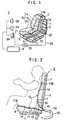
- a vehicle seat 2 according to a first embodiment of the invention is used in an automobile which is equipped an air conditioner (air discharging mechanism) 3.
- the vehicle seat 2 includes a seat pad 6 which is mounted on a seat cushion frame 4 and a seat pad 7 for a back rest which is mounted on a seat back frame 5.
- the vehicle seat 2 comprises a lower layer 10 formed by a sheet-like member (non-permeable member) such as formed from vinyl chloride, leather or the like, a permeable layer 11 mounted on top of the lower layer 10 and formed by a cushion member (air channel member) having a clearance formed therein through which an air can flow, and an upper layer 12 mounted on the upper surface of the permeable layer 11 and including a non-permeable section 13 and a permeable section 14 disposed at given locations thereon, it being understood that the lower layer 10, the permeable layer 11 and the upper layer 12 are formed in integrally continuous manner and disposed toward the front surface of the vehicle 2 (see Fig. 4).
- a sheet-like member non-permeable member
- a permeable layer 11 mounted on top of the lower layer 10 and formed by a cushion member (air channel member) having a clearance formed therein through which an air can flow
- an upper layer 12 mounted on the upper surface of the permeable layer 11 and including a non-permeable section 13
- the permeable section 14 in the upper layer12 is formed by a permeable textile fabric or meshy cloth and is disposed substantially in conformity to locations C1 (thigh and buttocks) and C2 (back) (see Fig. 3) which are contacted by a user as he sits on the seat.
- the permeable section 14 is disposed in a range narrower than the contacted locations C1, C2. (The permeable section 14 is shown hatched in Figs.
- the non-permeable section 13 is formed by a sheet-like member having a heat insulating capability and is disposed at the location corresponding to the waste as a user sits on the seat, namely, over a given length across the seat pad 6 and the back rest 7 of the vehicle seat.
- the combination of the layers 10, 11 and 12 defines a ventilating structure on the front surface of the vehicle seat.
- the cushion member 11 exhibits a resilience and has a given thickness, and is formed by weaving a plastic mono-filament yarn in the manner of a pile yarn on a double pile loom into a honeycomb structure.
- an air inlet port 15 which is used to introduce the air into the permeable layer 11 is formed in the ventilating structure 10, 11, 12 at a location corresponding to the rear end of the seating pad 6 and the bottom of the back rest 7.
- a hose (introduction passage) 20, which is used to introduce part of an air at a given temperature which is delivered from an air conditioner 3 by providing a communication between the permeable layer 11 and an air discharge port 3A of the air conditioner 3, is connected to the air inlet port 15.
- the hose 20 is molded from synthetic resin into the configuration of bellows so as to be flexible and extensible/shrinkable. As shown in Fig.
- an adapter 21 attached to the inlet end is connected to the air discharge port 3A of the air conditioner 3 while a connector 22 attached to the outlet end is connected to the air inlet port 15.
- An air regulating valve 23 is connected in the hose 20 for adjustably throttling the internal air passage and for interrupting the air passage and releasing the air to the exterior. Accordingly, an air at a given temperature (cold or warm air) which is delivered from the air discharge port 3A of the air conditioner 3 is fed into the permeable layer 11 while its flow rate is adjusted by the air regulating valve 23.
- the adapter 21 comprises a foam molded product from foamed styrol or an elastically deformable molded product from urethane or the like which is molded in conformity to the configuration of the air discharge port 3A, or may comprise a joint member.
- a clearance 11A is formed at the front end of the seating pad 6 while a clearance 11B is formed at the upper end of the back rest 7.
- These clearances 11A, 11B cannot be contacted or blocked by a user when he sits on the vehicle seat 2, providing a communication between the interior and the exterior of the permeable layer 11. It will be noted that these clearances 11A, 11B are located to be most distant from the air inlet port 15. Accordingly, when the air is introduced into the permeable layer 11 from the exterior and the entire surface of the permeable section 14 of the upper layer 12 is blocked, the introduced air can find its way to the outside through the clearances 11A, 11B.
- the hose 20 is used to connect the air inlet port 15 and the air discharge port 3A of the air conditioner 3.
- an air at a given temperature (cold or warm air) from the discharge port 3A is introduced into the permeable layer 11 through the hose 20.
- the air introduced into the permeable layer 11 passes through a clearance defined within the cushion member 11 held sandwiched between the non-permeable section 13 and the lower layer 10, and branches into the both portions thereof which are disposed toward the seating pad 6 and the back rest 7.
- an air channel is formed within the cushion member 11 held sandwiched between such contacted area and the lower layer 10, whereby the introduced air flows in contact with the part of the body (thigh, buttocks, and back) in areas of contact with the seating pad 6 and the back rest 7 to be displaced externally through the clearances 11A, 11B.
- the air conditioner 3 it is possible to cool or warn part of the body (thigh, buttocks and back) immediately upon operating the air conditioner 3, thus achieving a comfortable seated condition at the same time as the air at a given temperature is introduced.
- the body can be cooled down when a cold air is introduced from the air conditioner 3 in hot season while the body can be warmed when a warm air is introduced in cold season. Because the introduced air at a given temperature flows in direct contact with the body of the user in permeable sections 14 which are contacted by the user, there can be no sweating or no transfer of the heat from the seat to the user, again achieving a comfortable seated condition. Because the air regulating valve 23 is provided in the hose 20, the flow rate of the introduced air can be adjusted, thus controlling the comfortableness in accordance with the sensation of the user to hotness and coldness.
- the air introduced at a given temperature is brought into direct contact with the body of the user, there is no need to provide a large temperature differential of the air temperature with respect to the bodily temperature.
- the operating cost can be reduced.
- the power dissipation of the air conditioner, and hence the fuel cost can be reduced.
- the provision of the non-permeable section 13 having a heat insulating capability between the seating pad 6 and the back rest 7 avoids an adverse influence of the air temperature upon the waste of the user.
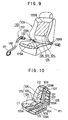
- vehicle seats 32, 42 and 48 according to a second, a third, and a fourth embodiment of the invention will be described. It is to be noted that parts corresponding to those shown in the first embodiment are designated like reference numerals and characters as used before.
- the permeable cushion member 11 disposed between the upper layer 12 and the lower layer 10 is replaced by a non-permeable cushion member (filler member) 33 substantially at the center of the non-permeable section 13 to define a non-permeable layer, and communication paths 34, 35 are formed on the opposite lateral sides of the non-permeable layer 33 for providing a communication between the permeable layer disposed toward the seating pad 6 and the permeable layer 11 disposed toward the back rest 7.
- air inlet ports 15A, 15B are provided for connection with branched connector 22A of the hose 20.
- the non-permeable layer 33 of the vehicle seat 32 there is no air flow through the non-permeable layer 33 of the vehicle seat 32, allowing an adverse influence of the temperature of the introduced air upon the waste to be more completely eliminated as compared with the vehicle seat 2 according to the first embodiment in which the non-permeable section is defined by a sheet member having a heat insulating capability.
- an air inlet port 15C is disposed forwardly of the seating pad 6 of the seat 42, and a non-permeable section 43 is formed in the upper layer 12 adjacent to the air inlet port 15C, thus forming a passage to the permeable-section 14.
- an air inlet port 45 is disposed on one of the lateral sides of the fold between the seating pad of the back rest 7 of the seat 48 for connection with the hose 20, in contradistinction to the vehicle seat 42 according to the third embodiment in which the air inlet port 15C connected with the hose 20 is disposed forwardy of the seating pad 6.
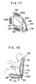
- FIG. 8 shows a vehicle seat 52 according to a fifth embodiment of the invention.
- a lower layer 10 formed by a non-permeable sheet-like member such as formed from vinyl chloride, leather or the like, a permeable layer 11 mounted on top of the lower layer 10 and formed by a permeable cushion member having pores formed therein through which an air can flow, and an upper layer 64 mounted to cover the upper surface of the permeable layer 11 and formed by a pair of sheet-like non-permeable members 62 and also including clearances 63A, 63B, which provide a communication between the permeable layer 11 and the exterior, formed at given locations around its outer edge, are formed in an integrally continuous manner and disposed toward the front surface of the seat 52.
- a non-permeable heat insulator 65 formed by a sheet-like member having a heat insulating capability, is disposed between a seating pad 56 and a back rest 57 of the seat 52. It will be seen that the respective layers 10, 11 and 64 constitute together a ventilating structure on the front surface of the seat 52. The back surface of the vehicle seat 52 is connected with a hose 20 communicating with the ventilating structure 10, 11, 64 and introducing an air at a given temperature from the air conditioner 3 into the permeable layer 11.
- the air flows in branched manner toward the seating pad 56 and the back rest 57, defining an air channel within the permeable layer 11 which is held sandwiched between the upper layer 64 and the lower layer 10 while the air which worked is externally displaced through paths 63A, 63B. Since the introduced air at the given temperature flows in contact with the rear surface of the non-permeable members 62 which are in contact with the user, the body of the user can be cooled or warmed in accordance with the temperature of the introduced air. Since a direct contact of the introduced air with the user is avoided, the air which is strongly cooled or warmed can be introduced without causing a discomfort since the air temperature is tempered when being conveyed to the user, thus achieving a comfortable seated condition.
- the permeable section 14 is formed in a range which is narrower than contacted locations C1, C2 (see Fig. 3) when a user is seated upon the seat, it should be understood that the permeable section may be formed substantially in conformity to the contacted locations C1, C2 or in a range slightly greater than such contacted locations, allowing the air which is introduced from the non-contacted permeable section 14 to be vented externally. In this instance, it is unnecessary to provide the clearances 11A, 11B. While the embodiments have been described as the invention is applied to a vehicle such as an automobile, it should be understood that the invention is not limited thereto, but is equally applicable to other vehicles such as aircrafts or marine vessels.
- the vehicle seat is connected with an air conditioner to introduce a cold or a warm air into the seat
- the invention is not limited thereto, but that it is only necessary that the air sheet be connected to an external air discharging mechanism such as a blower or drier, for example, for introducing an air at a normal temperature or a dry air to improve the comfortableness.
- the hose is connected to each seat, the hose may be branched to connect with a plurality of seats. The provision of the air regulating valve 13 can be dispensed with if the flow rate from the air conditioner 3 is adjusted.
- part of the hose 20 may be assembled into the vehicle seat 2, thus reducing the exposed appearance of the hose 20.
- the body of the user can be cooled or warmed immediately upon introducing the air at a given temperature into the seat from air discharge mechanism, thus providing a comfortable seated condition at the same time as the air is introduced. Since the ventilating structure is provided for each seat, a comfortable seated condition can be assured for each individual user without being influenced by the temperature within the compartment or the location of the seat. Since the air from the air discharge mechanism is allowed to contact part of the body of the user directly, the temperature of the introduced air can be controlled in accordance with a temperature differential relative to the bodily temperature, thus suppressing an operating cost as compared with a conventional practice in which the temperature of the air within the compartment is adjusted by means of the air conditioner. In addition, the vehicle seat can be manufactured inexpensively with a simple construction. Because the ventilating structure is provided inside the seat, the free space within the compartment can be increased to enhance the comfortability as compared with the provision of the air cushion on the seat as is conventional.
- the body of the user when the air from the air discharge mechanism is introduced into the ventilating structure of the seat, the body of the user can be cooled or warmed through the non-permeable member interposed. Accordingly if a strongly cold or warmed air is introduced into the seat, the air cannot contact the user directly, assuring a comfortable condition.
- a vehicle seat assembly 110 according to a sixth embodiment of the invention will now be described.
- the vehicle seat assembly is used on an automobile equipped with an external air discharge mechanism, not shown, such as an air conditioner, a blower, a heater or the like, for example.
- the vehicle seat assembly 110 comprises a seat 109, and an introduction hose assembly 112 which connects the seat 109 with an external air discharging mechanism.
- the seat 109 includes a seating pad 106 mounted on a seat cushion frame 104 and a seat pad 107 mounted on a seat back frame 105 to provide a back rest.
- the seat 109 comprises a lower layer 121 formed by a non-permeable sheet-like member such as formed from vinyl chloride, leather or the like, a permeable layer 122 mounted on top of the lower layer 121 and formed by a cushion member having pores formed therein through which an air can flow, and an upper layer 125 mounted on the upper surface of the permeable layer 122 and having a non-permeable section 123 and a permeable section 124 formed at given locations thereon, these layers being formed in an integrally continuous manner.
- a non-permeable sheet-like member such as formed from vinyl chloride, leather or the like
- a permeable layer 122 mounted on top of the lower layer 121 and formed by a cushion member having pores formed therein through which an air can flow
- an upper layer 125 mounted on the upper surface of the permeable layer 122 and having a non-permeable section 123 and a permeable section 124 formed at given locations thereon, these layers being formed in an integrally continuous manner.
- the cushion member 122 is a resilient, foldable and flexible cushion member having a given thickness, and is provided by weaving a plastic mono-filament yarn in the manner of a pile yarn on the double pile loom into a honeycomb structure as shown in Fig. 14. Clearances 125A, 125B are formed in the upper layer at the front end of the seating pad and at the upper end of the back rest, respectively, and these clearances cannot be contacted or blocked by the user when he sits on the seat 109, thus maintaining a communication between the interior and the exterior of the permeable layer 122.
- the permeable section 124 of the upper layer 125 is formed by a permeable textile fabric or a meshy cloth, and is formed substantially in conformity to the locations C1 (thigh, buttocks) and C2 (back) which are contacted when a user sits on the seat.
- the permeable section 124 is formed in a range slightly narrower than the contacted locations C1, C2.
- the non-permeable section 123 is formed by a heat insulating sheet-like member, and is formed to a given length along the fold between the seating pad and the back rest of the seat 109 so as to correspond to the waste of the user when he sits on the seat.
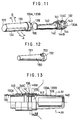
- the introduction hose assembly 112 comprises a flexible and extensible/shrinkable hose 130 which is molded from a synthetic resin into the configuration of the bellows, an adapter 131 attached to an inlet end of the hose 130 and connected to an air discharge mechanism so as to cover an air discharge port thereof, and a connector 132 attached to an outlet end of the hose 130.
- the seat 109 is provided with air inlet ports disposed on the opposite lateral sides of the fold P1 between the seating pad and the back rest, and connector receivers 133A, 133B are mounted on these air inlet ports.
- the connector 132 of the introduction hose assembly 112 is fitted into one of the connector receivers 133A, 133B for purpose of connection.
- each of the connector receivers 133A, 133B includes a sleeve of a reduced diameter 139 having a pair of elongate slots 134, 135 formed at given circumferential positions which depend on an angle of inclination between the seating pad and the back rest, which slots open into the cushion member 122 disposed toward the seating pad (indicated by an arrow A shown in Figs. 11, 14 and 15) and into the cushion member 122 disposed toward the back rest of the seat 109 (see arrow B shown in Figs 11,14 and 15).
- Fig. 11 Referring to Fig.
- each of the connector receivers 133A, 133B includes a sleeve of an increased diameter 136 which continues from the outer periphery of the sleeve 139 and having engaging grooves 137 (137A, 137B, 137C) formed at given circumferential positions around its inner periphery.
- each of the connector receivers 133A, 133B is formed with a reference indicator 138 which represents a rotational position of the connector 132 relative to either connector receiver 133A, 133B.
- the connector 132 comprises a split sleeve 140 which is slidable and rotatable when fitted into the sleeve 139, a sleeve-like portion 142 which is formed in a manner corresponding to the sleeve 136 of an increasing diameter of either connector receiver 133A, 133B and having a detent pawl 141 which is resiliently engaged in one of the engaging grooves 137, and a larger diameter portion 143 formed on the side of the sleeve-like portion 142 disposed toward the hose 130 and which is brought into abutment against the indicator 138 on either connector receiver 133A, 133B.
- the larger diameter portion 143 is rotatably connected to a connection sleeve 130A which is attached to the hose 130.
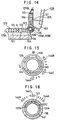
- the split sleeve 140 blocks either one of the elongate slots 134, 135 or open both of them depending on the rotational position, thus selectively guiding the air at a given temperature which is introduced through the introduction hose assembly 112 from an external air discharge mechanism, not shown, such as an air conditioner, a blower, a heater or the like, into at least one of the cushion members 122 of the seat 109 which are disposed toward the seating pad and the back rest.
- the sleeve-like portion 142 is formed with an L-shaped cut-in groove around the detent pawl 141, thus causing the detent pawl 141 to be elastically displaced in a radial direction.
- the detent pawl 141 fits in one of the engaging grooves 137 formed around the inner periphery of the sleeve 136 of an increase diameter of the corresponding connector receiver 133A, 133B, preventing a further rotation of the connector 132 and also serving to prevent the latter from being withdrawn.
- the larger diameter portion 143 of the connector 132 is provided with indicators 144A, 144B, 144C representing given circumferential positions of the connector 132.
- Indicator 144A represents the introduction of the air toward the seating pad of the seat 109; indicator 144B represents the introduction of the air toward the back rest; and indicator 144C represents the introduction of the air toward both the seating pad and the back rest.
- the split sleeve 140 opens or blocks a given one or ones of the elongate slots 134, 135 depending on the rotational position.
- the detent pawl 141 fits in one of the engaging grooves 137A, 137B, 137C which corresponds to one of the indicators 144A, 144B, 144C, thus blocking further rotation of the connector 132 and preventing the connector 132 from being withdrawn from either connector receiver 133A, 133B.
- a cylindrical plug member 150 is inserted into either connector receiver 133A, 133B to interrupt a communication between the inside and the outside of the seat 109.
- the plug member 150 comprises a sleeve of a reduced diameter 151 which is inserted into one of the connector receivers 133A, 133B to block elongate slots 134, 135 and also carrying a projection 153 which can fit in one of the engaging grooves 137, and a sleeve of an increased diameter 152 formed on the outside of the sleeve 151 and which is adapted to be brought into abutment against the indicator 138.
- the plug member 150 is mounted in the other of the connector receivers 133A, 133B for a balanced guidance of the introduced air in a desired flow direction while preventing a leakage of the introduced air in the permeable layer 122 from the other connector receiver.
- the adapter 131 comprises a base 160 connected with the hose 130 and having an enlarging air inlet port 161, and a plurality of applied pieces 162A, 162B, 162C, 162D mounted in a rockable manner along the air inlet port 161 to cover an air discharge port of an external air discharge mechanism, not shown. It will be seen that an adhesive material 163 is applied to the inside of each of the applied pieces 162A-162D so as to surround the air discharge port in accordance with the configuration and size of the air discharge port.
- the applied pieces 162A-162D are designed to allow the air to be efficiently to be received by the introduction hose assembly 112 if they do not completely cover the air discharge port of an air conditioner which is mounted on the vehicle as the adapter 131 is connected to the air conditioner, or in the presence of any slight clearances therebetween.
- the connector 132 of the introduction hose assembly 112 is connected to one of the connector receivers 133A, 133B in the seat 109 while the plug member 150 is mounted in the other connector receiver.
- the applied pieces 162A, 162B, 162C, 162D of the adapter 131 are applied in surrounding relationship with one of air discharge ports of an external air discharge mechanism, for example, an air conditioner, not shown, thus covering the selected one of the air discharge ports.
- the split sleeve 140 opens the elongate slot 134 and blocks the elongate 135, and at this position of the sleeve, the detent pawl 141 fits in the engaging groove 137A, thus locking the connector 132 with respect to the corresponding connector receiver 133A or 133B.
- the engine is then started to operate the external air discharge mechanism, not shown, whereupon an air at a given temperature (a cold or warm air) from the air discharge port of the air conditioner is introduced into one of the permeable layers 122 which is disposed toward the seating pad of the seat 109 through the introduction hose assembly 112.
- a given temperature a cold or warm air
- the split sleeve 140 opens the elongate slot 135 and blocks the elongate slot 134, and the detent pawl 141 fits in the engaging groove 137B. Accordingly the air is introduced into the permeable layer which is disposed toward the back rest.
- the split sleeve 140 opens the both elongate slots 134, 135, whereby the air is introduced into the permeable layer 122 disposed toward both the seating pad and the back rest.
- the air which is introduced into the permeable layer 122 of the seat 109 through the introduction hose assembly 112 passes through the interior of at least one of the cushion members 122 which are disposed toward the seating pad or the back rest of the seat 109, and the air which flows into the permeable section 124 contacts part of the body (either back or the thigh, and buttocks) while the air which worked is displaced through discharge sections 125A, 125B.
- the connector 132 can be brought to a desired rotational position, thus controlling the direction of flow of the air which passes through the permeable layer 122 of the seat 109.
- the connector 132 in a manner to prevent the engagement of the detent pawl 141 with one of the engaging grooves 137 so that the indicator 138 is positioned intermediate the indicators 144A, 144B, 144C, thus adjusting the area of opening presented by the elongate slots 134, 135 to control the flow rate of the air which is introduced into the permeable layer 122 of the seat 109. Since the applied pieces 162A-162D of the adapter 131 are applied around the air discharge port to cover it, the adapter 131 of the introduction hose assembly 112 can accommodate for a variety of air discharge ports without being influenced by the configuration or size of such air discharge port.
- the direction of flow of the air which is introduced into the permeable layer of the seat can be freely changed with a simple construction, a fine adjustment of the flow rate of the air is permitted, and an accommodation for a variety of configurations of the air discharge port is achieved.
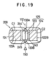
- Fig. 19 shows a vehicle seat 209 according to a seventh embodiment of the invention.
- the permeable cushion member 122 which is interposed between the upper layer 125 and the lower layer 121 is replaced by a non-permeable cushion member 243 to define a non-permeable layer substantially at the center of the non-permeable section 123 in the upper layer 125.
- Permeable cushion members 122 are disposed between the upper and the lower layer 121, 125 on the opposite sides of the non-permeable layer 243, thus forming communication paths 244, 245 which provide a communication between the permeable layer 122A disposed toward the seating pad and the permeable layer 122B disposed toward the back rest. Accordingly, an adverse influence of the temperature of the introduced air upon the waste can be completely eliminated when the air is introduced into the seat 209.
- three engaging grooves are formed at a given circumferential spacing in the connector receiver, but it should be understood that the invention is not limited thereto, but that a number of engaging grooves may be provided circumferentially to define the circumferential position of the split sleeve 140 more finely to enable it to be locked for each choice of the area of opening provided by the elongate slots 134, 135.
- the permeable section 124 is provided on the surface of the permeable cushion member 122, the invention is not limited thereto. Instead, the entire front surface of the cushion member 122 may be formed by non-permeable thin sheet to prevent a direct contact of the air with the body of the user while allowing the air temperature to be transmitted to the body through the sheet.
- a highly heat insulating non-permeable member may be provided in a region surrounding the waste.
- the external air discharge mechanism such as an air conditioner
- the introduction hose assembly 112 need not be provided.
- the introduction passage may be provided below the floor of the vehicle and connected to the seat through an opening formed in the floor. In this instance, the hose does not appear above the floor, thus preventing any interference with the user.
- the connector is fitted to the connector receiver and is then turned, but the invention is not limited thereto, but the air control can also be achieved by an axial displacement between the connector and the connector receiver.
- the direction of flow of the air which is introduced into the permeable layer can be freely changed with a simple construction, and the flow rate of the air which is introduced into the permeable layer can be adjusted, thus improving the comfortability.
- the air channel is previously assembled into the seat, a mere connection of the introduction passage allows an external air supply to be utilized, thus improving the convenience.
- an accommodation for a variety of differing types of external air discharge ports is provided, thus enhancing the universal applicability of the introduction hose, permitting a reduction in the manufacturing cost.
Landscapes
- Engineering & Computer Science (AREA)
- Mechanical Engineering (AREA)
- Aviation & Aerospace Engineering (AREA)
- Transportation (AREA)
- Power Engineering (AREA)
- Physics & Mathematics (AREA)
- Thermal Sciences (AREA)
- Chair Legs, Seat Parts, And Backrests (AREA)
- Seats For Vehicles (AREA)
- Air-Conditioning For Vehicles (AREA)
Applications Claiming Priority (4)
| Application Number | Priority Date | Filing Date | Title |
|---|---|---|---|
| JP284679/96 | 1996-10-07 | ||
| JP8284679A JP2947187B2 (ja) | 1996-10-07 | 1996-10-07 | 車両用座席 |
| JP24946997A JP3306583B2 (ja) | 1997-08-29 | 1997-08-29 | 車両用座席 |
| JP249469/97 | 1997-08-29 |
Publications (1)
| Publication Number | Publication Date |
|---|---|
| EP0834421A1 true EP0834421A1 (fr) | 1998-04-08 |
Family
ID=26539310
Family Applications (1)
| Application Number | Title | Priority Date | Filing Date |
|---|---|---|---|
| EP97117325A Withdrawn EP0834421A1 (fr) | 1996-10-07 | 1997-10-07 | Siège de véhicule |
Country Status (6)
| Country | Link |
|---|---|
| US (1) | US5918930A (fr) |
| EP (1) | EP0834421A1 (fr) |
| KR (1) | KR100305600B1 (fr) |
| CN (1) | CN1079750C (fr) |
| AU (1) | AU702397B2 (fr) |
| TW (1) | TW429902U (fr) |
Cited By (38)
| Publication number | Priority date | Publication date | Assignee | Title |
|---|---|---|---|---|
| DE19736951A1 (de) * | 1997-08-25 | 1999-03-04 | Titv Greiz | Sitzaufbau, insbesondere für Sitze in Kraftfahrzeugen |
| WO1999058907A1 (fr) * | 1998-05-12 | 1999-11-18 | Amerigon, Inc. | Echangeur de chaleur thermoelectrique |
| US6907739B2 (en) | 1998-05-12 | 2005-06-21 | Lon E. Bell | Thermoelectric heat exchanger |
| FR2874551A1 (fr) * | 2004-08-27 | 2006-03-03 | Valeo Climatisation Sa | Dispositif de jonction aeraulique entre l'assise et le dossier rabattable d'un seige, de vehicule notamment |
| WO2006131189A1 (fr) * | 2005-06-08 | 2006-12-14 | Bayerische Motoren Werke Aktiengesellschaft | Siege de vehicule comportant une couche de ventilation sous un revetement de surface |
| GB2438065A (en) * | 2006-05-08 | 2007-11-14 | Lear Corp | Connector for airflow between an air conditioning device and a plenum member in a vehicle seat |
| DE102006054860A1 (de) * | 2006-11-20 | 2008-05-21 | Proseat Gmbh & Co. Kg | Baugruppe für einen Sitz |
| WO2011011294A1 (fr) * | 2009-07-18 | 2011-01-27 | Jacobo Frias | Système de commande de température non gonflable |
| US7926293B2 (en) | 2001-02-09 | 2011-04-19 | Bsst, Llc | Thermoelectrics utilizing convective heat flow |
| US7942010B2 (en) | 2001-02-09 | 2011-05-17 | Bsst, Llc | Thermoelectric power generating systems utilizing segmented thermoelectric elements |
| US7946120B2 (en) | 2001-02-09 | 2011-05-24 | Bsst, Llc | High capacity thermoelectric temperature control system |
| US8069674B2 (en) | 2001-08-07 | 2011-12-06 | Bsst Llc | Thermoelectric personal environment appliance |
| ITPI20120103A1 (it) * | 2012-10-05 | 2014-04-06 | Giuliano Martelli | Cuscino aria termo riscaldato caldo freddo |
| US9006556B2 (en) | 2005-06-28 | 2015-04-14 | Genthem Incorporated | Thermoelectric power generator for variable thermal power source |
| US9121414B2 (en) | 2010-11-05 | 2015-09-01 | Gentherm Incorporated | Low-profile blowers and methods |
| US9310112B2 (en) | 2007-05-25 | 2016-04-12 | Gentherm Incorporated | System and method for distributed thermoelectric heating and cooling |
| US9335073B2 (en) | 2008-02-01 | 2016-05-10 | Gentherm Incorporated | Climate controlled seating assembly with sensors |
| US9365090B2 (en) | 2004-05-10 | 2016-06-14 | Gentherm Incorporated | Climate control system for vehicles using thermoelectric devices |
| US9447994B2 (en) | 2008-10-23 | 2016-09-20 | Gentherm Incorporated | Temperature control systems with thermoelectric devices |
| US9555686B2 (en) | 2008-10-23 | 2017-01-31 | Gentherm Incorporated | Temperature control systems with thermoelectric devices |
| US9622588B2 (en) | 2008-07-18 | 2017-04-18 | Gentherm Incorporated | Environmentally-conditioned bed |
| US9662962B2 (en) | 2013-11-05 | 2017-05-30 | Gentherm Incorporated | Vehicle headliner assembly for zonal comfort |
| US9685599B2 (en) | 2011-10-07 | 2017-06-20 | Gentherm Incorporated | Method and system for controlling an operation of a thermoelectric device |
| US9857107B2 (en) | 2006-10-12 | 2018-01-02 | Gentherm Incorporated | Thermoelectric device with internal sensor |
| US9863672B2 (en) | 2005-04-08 | 2018-01-09 | Gentherm Incorporated | Thermoelectric-based air conditioning system |
| US9989267B2 (en) | 2012-02-10 | 2018-06-05 | Gentherm Incorporated | Moisture abatement in heating operation of climate controlled systems |
| US10005337B2 (en) | 2004-12-20 | 2018-06-26 | Gentherm Incorporated | Heating and cooling systems for seating assemblies |
| US10106011B2 (en) | 2009-05-18 | 2018-10-23 | Gentherm Incorporated | Temperature control system with thermoelectric device |
| US10405667B2 (en) | 2007-09-10 | 2019-09-10 | Gentherm Incorporated | Climate controlled beds and methods of operating the same |
| US10603976B2 (en) | 2014-12-19 | 2020-03-31 | Gentherm Incorporated | Thermal conditioning systems and methods for vehicle regions |
| US10625566B2 (en) | 2015-10-14 | 2020-04-21 | Gentherm Incorporated | Systems and methods for controlling thermal conditioning of vehicle regions |
| US10991869B2 (en) | 2018-07-30 | 2021-04-27 | Gentherm Incorporated | Thermoelectric device having a plurality of sealing materials |
| US11033058B2 (en) | 2014-11-14 | 2021-06-15 | Gentherm Incorporated | Heating and cooling technologies |
| US11152557B2 (en) | 2019-02-20 | 2021-10-19 | Gentherm Incorporated | Thermoelectric module with integrated printed circuit board |
| US11240882B2 (en) | 2014-02-14 | 2022-02-01 | Gentherm Incorporated | Conductive convective climate controlled seat |
| US11639816B2 (en) | 2014-11-14 | 2023-05-02 | Gentherm Incorporated | Heating and cooling technologies including temperature regulating pad wrap and technologies with liquid system |
| US11857004B2 (en) | 2014-11-14 | 2024-01-02 | Gentherm Incorporated | Heating and cooling technologies |
| US11993132B2 (en) | 2019-11-26 | 2024-05-28 | Gentherm Incorporated | Thermoelectric conditioning system and methods |
Families Citing this family (46)
| Publication number | Priority date | Publication date | Assignee | Title |
|---|---|---|---|---|
| US6254179B1 (en) * | 1997-11-06 | 2001-07-03 | Webasto Thermosysteme Gmbh | Air conditionable vehicle seat |
| US6786541B2 (en) | 2001-01-05 | 2004-09-07 | Johnson Controls Technology Company | Air distribution system for ventilated seat |
| US6629724B2 (en) | 2001-01-05 | 2003-10-07 | Johnson Controls Technology Company | Ventilated seat |
| US7040710B2 (en) | 2001-01-05 | 2006-05-09 | Johnson Controls Technology Company | Ventilated seat |
| DE20112473U1 (de) * | 2001-07-28 | 2002-12-19 | Johnson Controls Gmbh | Klimatisiertes Polsterteil für einen Fahrzeugsitz |
| DE20120516U1 (de) * | 2001-12-19 | 2003-04-30 | Johnson Controls Gmbh | Belüftungssystem für ein Polsterteil |
| US6893086B2 (en) * | 2002-07-03 | 2005-05-17 | W.E.T. Automotive Systems Ltd. | Automotive vehicle seat insert |
| AU2003290662A1 (en) * | 2002-11-05 | 2004-06-07 | Witchie, Ronald, G. | An arrangement and method for providing an air flow within an upholstered seat |
| US7029065B2 (en) * | 2003-02-13 | 2006-04-18 | The Boeing Company | Ventilated seating system with improved low pressure performance |
| US7274007B2 (en) | 2003-09-25 | 2007-09-25 | W.E.T. Automotive Systems Ltd. | Control system for operating automotive vehicle components |
| US7425034B2 (en) * | 2003-10-17 | 2008-09-16 | W.E.T. Automotive Systems Ag | Automotive vehicle seat having a comfort system |
| US7461892B2 (en) | 2003-12-01 | 2008-12-09 | W.E.T. Automotive Systems, A.C. | Valve layer for a seat |
| DE102004030705B3 (de) * | 2004-06-25 | 2005-12-01 | Daimlerchrysler Ag | Luftversorgungseinrichtung für einen Fahrzeugsitz sowie Verfahren zum Betreiben derselben |
| US8783397B2 (en) | 2005-07-19 | 2014-07-22 | Bsst Llc | Energy management system for a hybrid-electric vehicle |
| JP4673692B2 (ja) * | 2005-07-19 | 2011-04-20 | 本田技研工業株式会社 | 車両における電気機器の冷却構造 |
| US7478869B2 (en) | 2005-08-19 | 2009-01-20 | W.E.T. Automotive Systems, Ag | Automotive vehicle seat insert |
| US7640753B2 (en) * | 2006-01-10 | 2010-01-05 | Delphi Technologies, Inc. | Control method for thermal regulation of a vehicle seat |
| US20070200398A1 (en) * | 2006-02-28 | 2007-08-30 | Scott Richard Wolas | Climate controlled seat |
| US7621135B2 (en) | 2006-03-15 | 2009-11-24 | Delphi Technologies, Inc. | Differential thermal conditioning of a vehicle seat |
| TWI494070B (zh) * | 2006-04-18 | 2015-08-01 | Seft Dev Lab Co Ltd | 間隔物及空調墊 |
| US20100155018A1 (en) | 2008-12-19 | 2010-06-24 | Lakhi Nandlal Goenka | Hvac system for a hybrid vehicle |
| US7779639B2 (en) | 2006-08-02 | 2010-08-24 | Bsst Llc | HVAC system for hybrid vehicles using thermoelectric devices |
| WO2009056112A1 (fr) * | 2007-10-29 | 2009-05-07 | W.E.T. Automotive Systems Ag | Dispositif de climatisation pour sièges |
| JP2011506178A (ja) * | 2007-12-10 | 2011-03-03 | ヴィー・エー・テー・オートモーティヴ・システムス・アクチェンゲゼルシャフト | 改良された空調モジュールおよび方法 |
| US20090218855A1 (en) * | 2008-02-26 | 2009-09-03 | Amerigon Incorporated | Climate control systems and devices for a seating assembly |
| DE102008017965B4 (de) * | 2008-04-08 | 2011-06-01 | W.E.T. Automotive Systems Ag | Belüftungseinrichtung |
| US8701422B2 (en) | 2008-06-03 | 2014-04-22 | Bsst Llc | Thermoelectric heat pump |
| US20100101239A1 (en) | 2008-10-23 | 2010-04-29 | Lagrandeur John | Multi-mode hvac system with thermoelectric device |
| DE202009017046U1 (de) | 2008-12-21 | 2010-05-12 | W.E.T. Automotive Systems Ag | Belüftungseinrichtung |
| DE202010002050U1 (de) * | 2009-02-18 | 2010-07-15 | W.E.T. Automotive Systems Ag | Klimatisierungseinrichtung für Fahrzeugsitze |
| KR102218137B1 (ko) | 2009-05-18 | 2021-02-22 | 젠썸 인코포레이티드 | 열전기 가열 및 냉각 시스템 |
| WO2011016284A1 (fr) * | 2009-08-03 | 2011-02-10 | 本田技研工業株式会社 | Structure de refroidissement pour un composant électrique haute tension pour véhicule |
| DE102011014516A1 (de) | 2010-04-06 | 2012-05-10 | W.E.T. Automotive Systems Ag | Multifunktionsprodukt |
| DE112012002935T5 (de) | 2011-07-11 | 2014-05-15 | Gentherm Inc. | Auf Thermoelektrik basierendes Wärmemanagement elektrischer Vorrichtungen |
| DE102012014678A1 (de) | 2011-08-19 | 2013-02-21 | W.E.T. Automotive Systems Ag | Heizeinrichtung |
| DE202011110107U1 (de) | 2011-11-17 | 2013-02-19 | W.E.T. Automotive Systems Ag | Temperier-Einrichtung |
| DE102012020516A1 (de) | 2011-12-09 | 2013-06-13 | W.E.T. Automotive Systems Ag | Temperier-Einrichtung für eine elektrochemische Spannungsquelle |
| DE102011121980A1 (de) | 2011-12-26 | 2013-06-27 | W.E.T. Automotive Systems Ag | Luftfördereinrichtung |
| CN103010058A (zh) * | 2012-12-04 | 2013-04-03 | 陈贺章 | 快速凉热座垫 |
| US9440572B2 (en) | 2013-05-20 | 2016-09-13 | David R. Hall | Heating, ventilation, and air conditioning seat assembly |
| US9818380B2 (en) * | 2013-11-18 | 2017-11-14 | Joseph E. Luttwak | Method for making light and stiff panels and structures using natural fiber composites |
| US11752737B2 (en) | 2013-11-18 | 2023-09-12 | Lingrove Inc. | Aesthetically-enhanced structures using natural fiber composites |
| JP6699508B2 (ja) * | 2016-10-26 | 2020-05-27 | トヨタ紡織株式会社 | 乗物用シート |
| GB2559243B (en) | 2016-12-01 | 2021-12-08 | Wonderland Switzerland Ag | Rebound bar adapted for being supported between a child safety seat and a backrest of a car seat and child safety seat assembly therewith |
| US10479237B2 (en) * | 2016-12-01 | 2019-11-19 | Wonderland Switzerland Ag | Rebound bar adapted for being supported between a child safety seat and a backrest of a car seat and child safety assembly therewith |
| US10974628B1 (en) * | 2018-12-18 | 2021-04-13 | Joseph Patrick Mooney | Apparatus for providing a car seat with ventilation |
Citations (11)
| Publication number | Priority date | Publication date | Assignee | Title |
|---|---|---|---|---|
| US2804913A (en) * | 1955-11-23 | 1957-09-03 | S E Hyman Company | Ventilated seat cover |
| JPH01172012A (ja) * | 1987-12-25 | 1989-07-06 | Suzuki Motor Co Ltd | 車両用座席における空調制御装置 |
| US4923248A (en) * | 1988-11-17 | 1990-05-08 | Steve Feher | Cooling and heating seat pad construction |
| DE3903303A1 (de) * | 1989-02-04 | 1990-08-09 | Wilfried Wunderatzke | Sitz, insbesondere fahrzeugsitz |
| EP0411375A1 (fr) * | 1989-08-04 | 1991-02-06 | FIAT AUTO S.p.A. | Siège pour véhicules, pourvus d'un compartiment passager à air conditionné |
| JPH0523235A (ja) * | 1991-07-19 | 1993-02-02 | Japan Gore Tex Inc | 座席シート |
| DE4200825A1 (de) * | 1992-01-15 | 1993-07-22 | Bayerische Motoren Werke Ag | Sitzaufbau |
| FR2694527A1 (fr) * | 1992-08-04 | 1994-02-11 | Baghini Deso | Système de climatisation pour sièges de véhicules automobile. |
| EP0582734A1 (fr) * | 1992-08-11 | 1994-02-16 | LEDA Logarithmic Electrical Devices for Automation S.r.l. | Siège chauffé électriquement pour véhicules automobiles |
| US5370439A (en) * | 1994-01-04 | 1994-12-06 | Lowe; Warren | Vehicle seat ventilation |
| DE4323164A1 (de) * | 1993-07-10 | 1995-01-12 | Harald Dipl Ing Austel | Sitzbelüftungssystem |
Family Cites Families (12)
| Publication number | Priority date | Publication date | Assignee | Title |
|---|---|---|---|---|
| GB929555A (en) * | 1960-08-03 | 1963-06-26 | Frank Karner | Air conditioned seat |
| JPS60142660A (ja) * | 1983-12-29 | 1985-07-27 | Nec Corp | デイジタル構内電子交換機の会議電話方式 |
| US4592926A (en) * | 1984-05-21 | 1986-06-03 | Machine Technology, Inc. | Processing apparatus and method |
| JPS63106358A (ja) * | 1986-10-24 | 1988-05-11 | Hitachi Ltd | 燃料噴射弁 |
| FR2630056B1 (fr) * | 1988-04-15 | 1992-03-06 | Renault | Siege ventile de vehicule |
| NL190601C (nl) * | 1989-07-10 | 1994-05-16 | John Hendricus Tol | Spelinrichting. |
| US5002336A (en) * | 1989-10-18 | 1991-03-26 | Steve Feher | Selectively cooled or heated seat and backrest construction |
| US5016302A (en) * | 1989-12-13 | 1991-05-21 | Yu Kaung M | Motive air seat cushion |
| US4997230A (en) * | 1990-01-30 | 1991-03-05 | Samuel Spitalnick | Air conditioned cushion covers |
| DE4228163A1 (de) * | 1992-08-25 | 1994-03-03 | Baumann Sabine | Auflage |
| US5524439A (en) * | 1993-11-22 | 1996-06-11 | Amerigon, Inc. | Variable temperature seat climate control system |
| US5626386A (en) * | 1996-07-16 | 1997-05-06 | Atoma International, Inc. | Air cooled/heated vehicle seat assembly |
-
1997
- 1997-10-03 AU AU39913/97A patent/AU702397B2/en not_active Ceased
- 1997-10-04 TW TW087215953U patent/TW429902U/zh not_active IP Right Cessation
- 1997-10-06 US US08/944,886 patent/US5918930A/en not_active Expired - Fee Related
- 1997-10-07 EP EP97117325A patent/EP0834421A1/fr not_active Withdrawn
- 1997-10-07 KR KR1019970051472A patent/KR100305600B1/ko not_active IP Right Cessation
- 1997-10-07 CN CN97118958A patent/CN1079750C/zh not_active Expired - Fee Related
Patent Citations (11)
| Publication number | Priority date | Publication date | Assignee | Title |
|---|---|---|---|---|
| US2804913A (en) * | 1955-11-23 | 1957-09-03 | S E Hyman Company | Ventilated seat cover |
| JPH01172012A (ja) * | 1987-12-25 | 1989-07-06 | Suzuki Motor Co Ltd | 車両用座席における空調制御装置 |
| US4923248A (en) * | 1988-11-17 | 1990-05-08 | Steve Feher | Cooling and heating seat pad construction |
| DE3903303A1 (de) * | 1989-02-04 | 1990-08-09 | Wilfried Wunderatzke | Sitz, insbesondere fahrzeugsitz |
| EP0411375A1 (fr) * | 1989-08-04 | 1991-02-06 | FIAT AUTO S.p.A. | Siège pour véhicules, pourvus d'un compartiment passager à air conditionné |
| JPH0523235A (ja) * | 1991-07-19 | 1993-02-02 | Japan Gore Tex Inc | 座席シート |
| DE4200825A1 (de) * | 1992-01-15 | 1993-07-22 | Bayerische Motoren Werke Ag | Sitzaufbau |
| FR2694527A1 (fr) * | 1992-08-04 | 1994-02-11 | Baghini Deso | Système de climatisation pour sièges de véhicules automobile. |
| EP0582734A1 (fr) * | 1992-08-11 | 1994-02-16 | LEDA Logarithmic Electrical Devices for Automation S.r.l. | Siège chauffé électriquement pour véhicules automobiles |
| DE4323164A1 (de) * | 1993-07-10 | 1995-01-12 | Harald Dipl Ing Austel | Sitzbelüftungssystem |
| US5370439A (en) * | 1994-01-04 | 1994-12-06 | Lowe; Warren | Vehicle seat ventilation |
Non-Patent Citations (2)
| Title |
|---|
| PATENT ABSTRACTS OF JAPAN vol. 13, no. 446 (M - 877) 6 October 1989 (1989-10-06) * |
| PATENT ABSTRACTS OF JAPAN vol. 17, no. 297 (C - 1068) 8 June 1993 (1993-06-08) * |
Cited By (63)
| Publication number | Priority date | Publication date | Assignee | Title |
|---|---|---|---|---|
| DE19736951A1 (de) * | 1997-08-25 | 1999-03-04 | Titv Greiz | Sitzaufbau, insbesondere für Sitze in Kraftfahrzeugen |
| US7178344B2 (en) | 1998-05-12 | 2007-02-20 | Amerigon, Inc. | Thermoelectric heat exchanger |
| USRE44272E1 (en) | 1998-05-12 | 2013-06-11 | Gentherm Incorporated | Thermoelectric heat exchanger |
| EP1429089A2 (fr) * | 1998-05-12 | 2004-06-16 | Amerigon, Inc. | Echangeur de chaleur thermoelectrique |
| US6907739B2 (en) | 1998-05-12 | 2005-06-21 | Lon E. Bell | Thermoelectric heat exchanger |
| US6223539B1 (en) | 1998-05-12 | 2001-05-01 | Amerigon | Thermoelectric heat exchanger |
| EP1429089A3 (fr) * | 1998-05-12 | 2005-07-06 | Amerigon, Inc. | Echangeur de chaleur thermoelectrique |
| WO1999058907A1 (fr) * | 1998-05-12 | 1999-11-18 | Amerigon, Inc. | Echangeur de chaleur thermoelectrique |
| US7942010B2 (en) | 2001-02-09 | 2011-05-17 | Bsst, Llc | Thermoelectric power generating systems utilizing segmented thermoelectric elements |
| US7926293B2 (en) | 2001-02-09 | 2011-04-19 | Bsst, Llc | Thermoelectrics utilizing convective heat flow |
| US7946120B2 (en) | 2001-02-09 | 2011-05-24 | Bsst, Llc | High capacity thermoelectric temperature control system |
| US8495884B2 (en) | 2001-02-09 | 2013-07-30 | Bsst, Llc | Thermoelectric power generating systems utilizing segmented thermoelectric elements |
| US8069674B2 (en) | 2001-08-07 | 2011-12-06 | Bsst Llc | Thermoelectric personal environment appliance |
| US9365090B2 (en) | 2004-05-10 | 2016-06-14 | Gentherm Incorporated | Climate control system for vehicles using thermoelectric devices |
| FR2874551A1 (fr) * | 2004-08-27 | 2006-03-03 | Valeo Climatisation Sa | Dispositif de jonction aeraulique entre l'assise et le dossier rabattable d'un seige, de vehicule notamment |
| US10005337B2 (en) | 2004-12-20 | 2018-06-26 | Gentherm Incorporated | Heating and cooling systems for seating assemblies |
| US9863672B2 (en) | 2005-04-08 | 2018-01-09 | Gentherm Incorporated | Thermoelectric-based air conditioning system |
| WO2006131189A1 (fr) * | 2005-06-08 | 2006-12-14 | Bayerische Motoren Werke Aktiengesellschaft | Siege de vehicule comportant une couche de ventilation sous un revetement de surface |
| US9006556B2 (en) | 2005-06-28 | 2015-04-14 | Genthem Incorporated | Thermoelectric power generator for variable thermal power source |
| US7607739B2 (en) | 2006-05-08 | 2009-10-27 | Lear Corporation | Air routing system and method for use with a vehicle seat |
| GB2438065B (en) * | 2006-05-08 | 2008-11-12 | Lear Corp | Air routing system and method for use with a vehicle seat |
| GB2438065A (en) * | 2006-05-08 | 2007-11-14 | Lear Corp | Connector for airflow between an air conditioning device and a plenum member in a vehicle seat |
| US9857107B2 (en) | 2006-10-12 | 2018-01-02 | Gentherm Incorporated | Thermoelectric device with internal sensor |
| DE102006054860B4 (de) * | 2006-11-20 | 2009-08-13 | Proseat Gmbh & Co. Kg | Baugruppe für einen Sitz |
| DE102006054860A1 (de) * | 2006-11-20 | 2008-05-21 | Proseat Gmbh & Co. Kg | Baugruppe für einen Sitz |
| US10464391B2 (en) | 2007-05-25 | 2019-11-05 | Gentherm Incorporated | System and method for distributed thermoelectric heating and cooling |
| US9310112B2 (en) | 2007-05-25 | 2016-04-12 | Gentherm Incorporated | System and method for distributed thermoelectric heating and cooling |
| US9366461B2 (en) | 2007-05-25 | 2016-06-14 | Gentherm Incorporated | System and method for climate control within a passenger compartment of a vehicle |
| US10405667B2 (en) | 2007-09-10 | 2019-09-10 | Gentherm Incorporated | Climate controlled beds and methods of operating the same |
| US10228166B2 (en) | 2008-02-01 | 2019-03-12 | Gentherm Incorporated | Condensation and humidity sensors for thermoelectric devices |
| US9651279B2 (en) | 2008-02-01 | 2017-05-16 | Gentherm Incorporated | Condensation and humidity sensors for thermoelectric devices |
| US9335073B2 (en) | 2008-02-01 | 2016-05-10 | Gentherm Incorporated | Climate controlled seating assembly with sensors |
| US9622588B2 (en) | 2008-07-18 | 2017-04-18 | Gentherm Incorporated | Environmentally-conditioned bed |
| US11297953B2 (en) | 2008-07-18 | 2022-04-12 | Sleep Number Corporation | Environmentally-conditioned bed |
| US10226134B2 (en) | 2008-07-18 | 2019-03-12 | Gentherm Incorporated | Environmentally-conditioned bed |
| US9447994B2 (en) | 2008-10-23 | 2016-09-20 | Gentherm Incorporated | Temperature control systems with thermoelectric devices |
| US9555686B2 (en) | 2008-10-23 | 2017-01-31 | Gentherm Incorporated | Temperature control systems with thermoelectric devices |
| US11203249B2 (en) | 2009-05-18 | 2021-12-21 | Gentherm Incorporated | Temperature control system with thermoelectric device |
| US10106011B2 (en) | 2009-05-18 | 2018-10-23 | Gentherm Incorporated | Temperature control system with thermoelectric device |
| WO2011011294A1 (fr) * | 2009-07-18 | 2011-01-27 | Jacobo Frias | Système de commande de température non gonflable |
| US9121414B2 (en) | 2010-11-05 | 2015-09-01 | Gentherm Incorporated | Low-profile blowers and methods |
| US10288084B2 (en) | 2010-11-05 | 2019-05-14 | Gentherm Incorporated | Low-profile blowers and methods |
| US11408438B2 (en) | 2010-11-05 | 2022-08-09 | Gentherm Incorporated | Low-profile blowers and methods |
| US9685599B2 (en) | 2011-10-07 | 2017-06-20 | Gentherm Incorporated | Method and system for controlling an operation of a thermoelectric device |
| US10208990B2 (en) | 2011-10-07 | 2019-02-19 | Gentherm Incorporated | Thermoelectric device controls and methods |
| US9989267B2 (en) | 2012-02-10 | 2018-06-05 | Gentherm Incorporated | Moisture abatement in heating operation of climate controlled systems |
| US10495322B2 (en) | 2012-02-10 | 2019-12-03 | Gentherm Incorporated | Moisture abatement in heating operation of climate controlled systems |
| ITPI20120103A1 (it) * | 2012-10-05 | 2014-04-06 | Giuliano Martelli | Cuscino aria termo riscaldato caldo freddo |
| US10266031B2 (en) | 2013-11-05 | 2019-04-23 | Gentherm Incorporated | Vehicle headliner assembly for zonal comfort |
| US9662962B2 (en) | 2013-11-05 | 2017-05-30 | Gentherm Incorporated | Vehicle headliner assembly for zonal comfort |
| US11240882B2 (en) | 2014-02-14 | 2022-02-01 | Gentherm Incorporated | Conductive convective climate controlled seat |
| US11240883B2 (en) | 2014-02-14 | 2022-02-01 | Gentherm Incorporated | Conductive convective climate controlled seat |
| US11033058B2 (en) | 2014-11-14 | 2021-06-15 | Gentherm Incorporated | Heating and cooling technologies |
| US11639816B2 (en) | 2014-11-14 | 2023-05-02 | Gentherm Incorporated | Heating and cooling technologies including temperature regulating pad wrap and technologies with liquid system |
| US11857004B2 (en) | 2014-11-14 | 2024-01-02 | Gentherm Incorporated | Heating and cooling technologies |
| US11358433B2 (en) | 2014-12-19 | 2022-06-14 | Gentherm Incorporated | Thermal conditioning systems and methods for vehicle regions |
| US10603976B2 (en) | 2014-12-19 | 2020-03-31 | Gentherm Incorporated | Thermal conditioning systems and methods for vehicle regions |
| US10625566B2 (en) | 2015-10-14 | 2020-04-21 | Gentherm Incorporated | Systems and methods for controlling thermal conditioning of vehicle regions |
| US11075331B2 (en) | 2018-07-30 | 2021-07-27 | Gentherm Incorporated | Thermoelectric device having circuitry with structural rigidity |
| US11223004B2 (en) | 2018-07-30 | 2022-01-11 | Gentherm Incorporated | Thermoelectric device having a polymeric coating |
| US10991869B2 (en) | 2018-07-30 | 2021-04-27 | Gentherm Incorporated | Thermoelectric device having a plurality of sealing materials |
| US11152557B2 (en) | 2019-02-20 | 2021-10-19 | Gentherm Incorporated | Thermoelectric module with integrated printed circuit board |
| US11993132B2 (en) | 2019-11-26 | 2024-05-28 | Gentherm Incorporated | Thermoelectric conditioning system and methods |
Also Published As
| Publication number | Publication date |
|---|---|
| CN1180628A (zh) | 1998-05-06 |
| CN1079750C (zh) | 2002-02-27 |
| KR19980032627A (ko) | 1998-07-25 |
| US5918930A (en) | 1999-07-06 |
| AU3991397A (en) | 1998-04-09 |
| AU702397B2 (en) | 1999-02-18 |
| TW429902U (en) | 2001-04-11 |
| KR100305600B1 (ko) | 2001-11-22 |
Similar Documents
| Publication | Publication Date | Title |
|---|---|---|
| US5918930A (en) | Vehicle seat | |
| EP0834420B1 (fr) | Ventilateur à utiliser avec un siège de véhicule | |
| USRE39394E1 (en) | Seat apparatus with air flow | |
| EP0912363B1 (fr) | Ensemble siege de vehicule refroidi/chauffe par air | |
| EP0206152B1 (fr) | Revêtement, notamment pour sièges de véhicules | |
| EP1349745B1 (fr) | Siege ventile transportable | |
| US6511125B1 (en) | Ventilated seat pad | |
| US7467823B2 (en) | Vehicle seat | |
| US5516189A (en) | Portable heated seat | |
| US5902014A (en) | Ventilated vehicle seat with a plurality of miniature ventilators | |
| US6247751B1 (en) | Seat, especially a vehicle seat | |
| GB2321722A (en) | Vehicle seat with heating and ventilation | |
| JP2004215748A (ja) | 車両用空調装置 | |
| WO2000018606A1 (fr) | Dispositif de ventilation pour siege | |
| JP2943729B2 (ja) | 車両の座席用通気具 | |
| JP3306583B2 (ja) | 車両用座席 | |
| JP2947187B2 (ja) | 車両用座席 | |
| JP3282555B2 (ja) | 車両の座席用通気具 | |
| JP2005143981A (ja) | 空調用シートマット及び空調用シート | |
| KR200369712Y1 (ko) | 냉난방 장치가 장착된 자동차용 시트 | |
| JPS6328930Y2 (fr) | ||
| JP2560860Y2 (ja) | 自動車用通気シート | |
| JPH0714951U (ja) | 空調シート | |
| JPH0682960U (ja) | 自動車の座席シートとシートクッション | |
| KR960007776Y1 (ko) | 자동차용 방석 |
Legal Events
| Date | Code | Title | Description |
|---|---|---|---|
| PUAI | Public reference made under article 153(3) epc to a published international application that has entered the european phase |
Free format text: ORIGINAL CODE: 0009012 |
|
| 17P | Request for examination filed |
Effective date: 19971007 |
|
| AK | Designated contracting states |
Kind code of ref document: A1 Designated state(s): CH DE DK ES FR GB GR IT LI NL SE |
|
| AX | Request for extension of the european patent |
Free format text: AL;LT;LV;RO;SI |
|
| AKX | Designation fees paid |
Free format text: CH DE DK ES FR GB GR IT LI NL SE |
|
| RBV | Designated contracting states (corrected) |
Designated state(s): CH DE DK ES FR GB GR IT LI NL SE |
|
| 17Q | First examination report despatched |
Effective date: 20020110 |
|
| GRAH | Despatch of communication of intention to grant a patent |
Free format text: ORIGINAL CODE: EPIDOS IGRA |
|
| STAA | Information on the status of an ep patent application or granted ep patent |
Free format text: STATUS: THE APPLICATION IS DEEMED TO BE WITHDRAWN |
|
| 18D | Application deemed to be withdrawn |
Effective date: 20030528 |