EP0819628B2 - Verfahren zum Entleeren von Schüttgut - Google Patents
Verfahren zum Entleeren von Schüttgut Download PDFInfo
- Publication number
- EP0819628B2 EP0819628B2 EP97111769A EP97111769A EP0819628B2 EP 0819628 B2 EP0819628 B2 EP 0819628B2 EP 97111769 A EP97111769 A EP 97111769A EP 97111769 A EP97111769 A EP 97111769A EP 0819628 B2 EP0819628 B2 EP 0819628B2
- Authority
- EP
- European Patent Office
- Prior art keywords
- container
- emptying
- suction removal
- suction
- loose material
- Prior art date
- Legal status (The legal status is an assumption and is not a legal conclusion. Google has not performed a legal analysis and makes no representation as to the accuracy of the status listed.)
- Expired - Lifetime
Links
- 239000000463 material Substances 0.000 title claims abstract description 15
- 238000000034 method Methods 0.000 title claims description 16
- 230000009969 flowable effect Effects 0.000 claims abstract 3
- 239000013590 bulk material Substances 0.000 description 26
- 239000011888 foil Substances 0.000 description 14
- 239000000725 suspension Substances 0.000 description 5
- 238000000605 extraction Methods 0.000 description 2
- 239000004744 fabric Substances 0.000 description 2
- 239000004033 plastic Substances 0.000 description 2
- 229920003023 plastic Polymers 0.000 description 2
- 208000032750 Device leakage Diseases 0.000 description 1
- 229910000831 Steel Inorganic materials 0.000 description 1
- 230000003247 decreasing effect Effects 0.000 description 1
- 230000000694 effects Effects 0.000 description 1
- 239000008187 granular material Substances 0.000 description 1
- 238000007654 immersion Methods 0.000 description 1
- 230000002093 peripheral effect Effects 0.000 description 1
- 230000003014 reinforcing effect Effects 0.000 description 1
- 239000007858 starting material Substances 0.000 description 1
- 239000010959 steel Substances 0.000 description 1
Images
Classifications
-
- B—PERFORMING OPERATIONS; TRANSPORTING
- B65—CONVEYING; PACKING; STORING; HANDLING THIN OR FILAMENTARY MATERIAL
- B65B—MACHINES, APPARATUS OR DEVICES FOR, OR METHODS OF, PACKAGING ARTICLES OR MATERIALS; UNPACKING
- B65B69/00—Unpacking of articles or materials, not otherwise provided for
- B65B69/0075—Emptying systems for flexible intermediate bulk containers [FIBC]
-
- B—PERFORMING OPERATIONS; TRANSPORTING
- B65—CONVEYING; PACKING; STORING; HANDLING THIN OR FILAMENTARY MATERIAL
- B65G—TRANSPORT OR STORAGE DEVICES, e.g. CONVEYORS FOR LOADING OR TIPPING, SHOP CONVEYOR SYSTEMS OR PNEUMATIC TUBE CONVEYORS
- B65G53/00—Conveying materials in bulk through troughs, pipes or tubes by floating the materials or by flow of gas, liquid or foam
- B65G53/34—Details
- B65G53/40—Feeding or discharging devices
- B65G53/42—Nozzles
-
- B—PERFORMING OPERATIONS; TRANSPORTING
- B65—CONVEYING; PACKING; STORING; HANDLING THIN OR FILAMENTARY MATERIAL
- B65G—TRANSPORT OR STORAGE DEVICES, e.g. CONVEYORS FOR LOADING OR TIPPING, SHOP CONVEYOR SYSTEMS OR PNEUMATIC TUBE CONVEYORS
- B65G65/00—Loading or unloading
- B65G65/30—Methods or devices for filling or emptying bunkers, hoppers, tanks, or like containers, of interest apart from their use in particular chemical or physical processes or their application in particular machines, e.g. not covered by a single other subclass
- B65G65/34—Emptying devices
- B65G65/36—Devices for emptying from the top
Definitions
- the invention relates to a method for emptying pourable bulk material from flexible, in particular bag or bag-like containers according to the preamble of patent claims 1, and 4.
- the starting materials to be processed are in the form of free-flowing bulk material. These are often supplied in filled containers, so-called.
- Octabin approaches which are lined with an inner film, d. H. have an inner foil bag that surrounds the bulk material.
- folding boxes with inner foil bag and fabric sacks or fabric-reinforced bags are known for storing and transporting bulk materials, also called big bags, in which no external reinforcing container is provided.
- the suction tube sucks away part of the bulk material, it no longer flows to the suction point in the case of bulk containers with a diameter of one meter or more.
- the problem is compounded by the fact that can hardly form a gradient from the container edge to the deepest suction.
- DE 4315 327 A1 proposes a method in which the container wall is tracked towards the suction device, i. is pulled radially inward. This results in a loosening of the material, for. B. by the container stands on a vibrating stop. However, a largely complete emptying of the container is usually not possible with this known method.
- the invention is therefore based on the object to provide a method for emptying pourable bulk material, which makes it possible in a simple manner, the bulk material when using an insertable from above into the container suction without manual operation of the suction as evenly as possible and completely from the Container to empty.
- the container with increasing emptying is at least as far pulled up that the lower portion of the container rests laterally on the suction of the suction device while the entire container is lifted with the bulk material residue from the ground.
- the entire container with the bulk material residue is lifted off the ground towards the end of the emptying process.
- the lifting of the container from the ground takes place when the applied tensile force is greater than the remaining weight of the bulk material including the suction head or suction tube.
- the residual material flows from the container edge forth towards the center, where it can be absorbed and sucked.
- the tensile force for the hoist is adjusted so that the tensile strength of the bag material is not exceeded.
- the lifting of the container signals the operator that the container is almost completely emptied, so that a container change can be initiated.
- the hoisting operation can be interrupted at any time, so that it is always possible to bring a different container to the extraction point with a required material change.
- holding elements which are arranged distributed regularly over the circumference of a holding frame, whereby a uniform pulling up and a uniform Loading of the container is ensured.
- These holding elements may in this case consist of clamping elements which comprise the container wall on both sides and clamp accordingly, or hooks, which are optionally hung on handles, which are provided at the upper edge of the container.
- the three-point suspension of the support frame is preferably made of three equal length ropes or chains, which are attached at its one end to a cable. This cable is suitably guided over pulleys to the lifting device, the pulleys can be attached to a surrounding the container to be emptied frame or directly to the building walls. Instead of a cable pull, a chain hoist can also be used.
- the emptying device consists essentially of an annular
- Holding frame 1 made of a rigid material, such as steel, which is suspended over three tension members in the form of ropes 2 on a cable 3.
- the cables 2 have the same length and are arranged regularly over the circumference of the support frame 1, d. H. fastened with its lower end to the support frame 1, while their opposite ends converge at a central connection point 4 and are fastened there to the cable 3.
- This three-point suspension ensures that the support frame 1 is suspended in a statically determined manner, lying in a horizontal plane.
- the clamping elements 5 are arranged regularly over the circumference of the holding frame 1, d. H. they have a uniform distance to each other, wherein they are pivotally mounted on the support frame 1.
- the clamping elements 5 are in the illustrated embodiment of two jaws, between which the film bag 6 can be inserted in its upper edge region, whereupon the jaws are pressed together and pinch the film bag between them.
- they can be provided with appropriate rubber surfaces or ribbed surfaces.
- the cable 3 is guided over guide rollers 8, 9, which are arranged on the upper side of a frame 10.
- This cable guide causes the cable 3 is initially guided vertically upwards to the top of the frame 10 and from there in the horizontal direction to the guide roller 9, which is located in the region of an upper corner of the frame 10. From the guide roller 9, the cable 3 in turn extends vertically downwards and is attached at its free end to a piston rod 11 of a lifting cylinder 12.
- the lifting cylinder 12 can be operated pneumatically or hydraulically. As an alternative to a lifting cylinder, it is also possible to use other alternative lifting devices such as an electric motor or a manually operable crank handle.
- octabin 7 (Figure 3A) can be retracted, for example by means of a forklift in the portal-like frame 10 until the octabin 7 in the center located below the hoist. Subsequently, the clamping elements 5 are clamped in the upper edge region of the foil bag 6 and introduced a suction device 15 from above into the foil bag 6.
- the suction device 15 can, as shown in FIGS.
- 3A and 3B be a buoyant suction head 18 connected to a suction hose 16 or, alternatively, only a suction pipe which is inserted from above into the film bag 6 like a vacuum cleaner pipe , The bulk material 13 can now be sucked out of the film bag 6 via the suction hose 16 of the suction device 15. Since the suction device 15 is known as such, this will not be described in detail.
- the film bag 6 is at least largely filled with the bulk material 13 so that it is pressed to the vicinity of the upper edge region of a rigid, octagonal outer casing 17 of the octabin 7 to the inner peripheral wall 17 of the outer casing 17 becomes. Since in this initial stage of the support frame 1 is in a relatively low position, the piston rod 11 of the lifting cylinder 12 is relatively far extended.
- the piston rod 11 is continuously retracted into the interior of the lifting cylinder 12, whereby the hoist raised accordingly and the foil bag 6 tightened upwards, d. H. is stretched. Since the holding frame 1 has a smaller diameter than the octabin 7, the upper edge region of the foil bag 6 is pulled simultaneously radially inwardly. As a result, the flow of the bulk material 13 is supported by the edge regions of the octabin 7 toward its center, where the suction head 18 of the suction device 15 is located.
- FIG. 3B The state of complete or at least almost complete emptying of the octabine 7 is shown in FIG. 3B.
- the film bag 6 assumes a substantially reduced diameter in relation to the rigid outer casing 17, wherein only in the lowermost region of the film bag 6 a residual amount 131 of bulk material is present.
- This residual amount 131 is located only below, but not laterally next to the suction head 18, on which the lower portion of the foil bag 6 rests laterally.
- the maximum extension and retraction lengths of the piston rod 11 are suitably determined by suitable limit switches, not shown, and are advantageously variable in order to adapt to different container heights.
- a cable pull 20, which is furthermore shown in FIGS. 3A and 3B, merely serves to balance the weight of the suction head 18 so that it rests on the bulk material 13 with a predetermined compressive force and floats on it. This weight compensation will not be described here.
Landscapes
- Engineering & Computer Science (AREA)
- Mechanical Engineering (AREA)
- Control And Other Processes For Unpacking Of Materials (AREA)
- Filling Or Emptying Of Bunkers, Hoppers, And Tanks (AREA)
Description
- Die Erfindung betrifft ein Verfahren zum Entleeren von rieselfähigem Schüttgut aus flexiblen, insbesondere sack- oder beutelartigen Behältnissen gemäß dem Oberbegriff der Patentansprüche 1, und 4.
- In vielen technischen Bereichen, insbesondere auch in der kunststoffverarbeitenden Industrie, liegen die zu verarbeitenden Ausgangsprodukte in Form von rieselfähigem Schüttgut vor. Diese werden häufig in befüllten Gebinden, sog. Oktabinbehältern, angeliefert, die mit einer innenliegenden Folie ausgekleidet sind, d. h. einen innenliegenden Foliensack aufweisen, der das Schüttgut umgibt. Weiterhin sind zur Aufbewahrung und zum Transport von Schüttgütern auch Faltboxen mit innenliegendem Foliensack und Gewebesäcke bzw. gewebeverstärkte Säcke bekannt, auch Big-Bags genannt, bei denen keinerlei äußerer Verstärkungsbehälter vorgesehen ist.
- Das Entleeren derartiger Behältnisse erfolgt hauptsächlich unter Verwendung von Absaugvorrichtungen, wobei ein Saugrohr wie eine Lanze in das Schüttgut gesteckt wird. Nachteilig ist hierbei jedoch, daß dieses Saugrohr durch eine Bedienungsperson ähnlich wie bei einem Staubsauger laufend manuell nachgeführt werden muß, um eine optimale Eintauchtiefe an der richtigen Absaugstelle zu gewährleisten. Hierdurch ist eine Bedienungsperson permanent oder zumindest über eine lange Zeit an der Absaugstelle gebunden. Weiterhin kann nicht vermieden werden, daß die Folie immer wieder an das Saugrohr angesaugt und dadurch der Absaugvorgang unterbrochen wird.
- Wird auf das manuelle Nachführen des Saugrohrs verzichtet, tritt der Effekt auf, daß das Saugrohr zwar einen Teil des Schüttgutes wegsaugt, aber bei Schüttgutgebinden mit einem Durchmesser von einem Meter oder mehr weit entfernt liegende Schüttgutanteile nicht mehr an die Absaugstelle fließen. Mit sinkendem Füllstand im Gebinde wird das Problem noch dadurch verstärkt, daß sich kaum mehr ein Gefälle vom Gebinderand zur tiefsten Absaugstelle bilden kann.
- Weiterhin ist es bekannt, gefüllte Gebinde mit innenliegender Folie, die das Schüttgut umgibt, auf eine Kippvorrichtung zu stellen und durch Neigen dieser Kippvorrichtung ein Auslaufen an einer bestimmten Stelle zu erreichen. Eine derartige Kippvorrichtung ist jedoch technisch aufwendig und benötigt einen großen Platzbedarf. Weiterhin ist mit diesen Kippvorrichtungen das teilweise Entleeren von Gewebesäcken nicht möglich.
- Aus der DE 421 18 331 A1 ist eine Entleervorrichtung bekannt, bei dem der Schüttgutbehälter in seinem oberen Randbereich Über Zugfedern aufgehängt ist, die ein in sich vertikal bewegbares Hebezeug darstellen. Die Aufhängepunkte, an denen diese Zugfedern aufgehängt sind, befinden sich knapp außerhalb der Grundfläche der Transportbehälter, so daß der obere Randbereich des Schüttgutbehälters aufgrund der Zugkraft der Federn radial nach außen gezogen wird. Bei dieser bekannten Aufhängung besteht jedoch die Gefahr, daß beim Aussaugen des Schüttgutbehälters mittels einer von oben eingeführten Absaugvorrichtung das Absaugen des Schüttguts hauptsächlich in der Mitte des Schüttgutbehälters und weniger in dessen Randbereichen erfolgt, so daß häufig Krater gebildet werden.
- Um diesem Problem zu begegnen, wird in der DE 4315 327 A1 ein Verfahren vorgeschlagen, bei dem die Behältniswandung zur Absaugvorrichtung hin nachgeführt, d.h. radial nach innen gezogen wird. Dabei erfolgt eine Auflockerung des Materials, z. B. indem das Behältnis dabei auf einer vibrierenden Abstelleinrichtung steht. Auch mit diesem bekannten Verfahren ist jedoch eine weitgehend restlose Entleerung des Behältnisses in der Regel nicht möglich.
- Der Erfindung liegt von daher die Aufgabe zugrunde, ein Verfahren zum Entleeren von rieselfähigem Schüttgut zu schaffen, die es auf einfache Weise ermöglicht, das Schüttgut bei Verwendung einer von oben her in das Behältnis einführbaren Absaugvorrichtung ohne manuelle Betätigung der Absaugvorrichtung möglichst gleichmäßig und vollständig aus dem Behältnis zu entleeren.
- Diese Aufgabe wird erfindungsgemäß durch die Merkmale der Patentansprüche 1, bzw. 4 gelöst.
- Bei dem erfindungsgemäßen Verfahren gemäß Patentanspruch 4 wird das Behältnis mit zunehmender Entleerung wenigstens soweit nach oben gezogen, daß der untere Bereich des Behältnisses seitlich am Absaugkopf der Absaugvorrichtung anliegt und dabei das gesamte Behältnis mit dem Schüttgutrest vom Boden abgehoben ist.
- Bei dem erfindungsgemäßen Verfahren gemäß Patentanspruch 1 wird gegen Ende des Entleerungsvorgangs das gesamte Behältnis mit dem Schüttgutrest vom Boden weggehoben.
- Das Wegheben des Behältnisses vom Boden erfolgt dann, wenn die angelegte Zugkraft größer ist als die verbleibende Gewichtskraft des Schüttgutes einschließlich des Absaugkopfes bzw. Absaugrohres. Dadurch fließt dem an der tiefsten Stelle des Behältnisses nunmehr angeordneten Absaugrohr oder Absaugkopf das Restmaterial vom Behältnisrand her zur Mitte hin zu, wo es aufgenommen und abgesaugt werden kann. Hierdurch ist eine fast restlose Entleerung ohne manuelles Zutun möglich. Die Zugkraft für das Hebezeug wird dabei so eingestellt, daß die Reißfestigkeit des Sackmaterials nicht überschritten wird. Ferner signalisiert das Hochheben des Behältnisses dem Betreiber, daß das Behältnis fast vollständig entleert ist, so daß ein Behältniswechsel eingeleitet werden kann.
- Der Hochziehvorgang kann zu jedem beliebigen Zeitpunkt unterbrochen werden, so daß es jederzeit möglich ist, bei einem erforderlichen Materialwechsel ein anderes Gebinde an die Absaugstelle zu bringen.
- Das Hochziehen des Behältnisses erfolgt mittels Halteelementen, die über den Umfang eines Halterahmens regelmäßig verteilt angeordnet sind, wodurch ein gleichmäßiges Hochziehen und eine gleichmäßige Belastung des Behältnisses gewährleistet wird. Diese Halteelemente können hierbei aus Klemmelementen bestehen, welche die Behältniswand beidseitig umfassen und entsprechend einklemmen, oder aus Haken, die ggf. an Henkeln eingehängt werden, die am oberen Rand des Behältnisses vorgesehen sind.
- Besonders vorteilhaft ist es, wenn der Halterahmen an drei Punkten aufgehängt ist, die über seinen Umfang regelmäßig verteilt sind. Eine derartige Dreipunktaufhängung bietet den Vorteil, daß der Halterahmen immer auf eine statisch bestimmte Weise horizontal ausgerichtet bleibt und ein unerwünschtes Kippen auch bei ungleichmäßiger Befestigung des Hebezeugs am Behältnis vermieden werden kann. Die Dreipunktaufhängung des Halterahmens besteht vorzugsweise aus drei gleich langen Seilen oder Ketten, die an ihrem einen Ende an einem Seilzug befestigt sind. Dieser Seilzug wird zweckmäßigerweise über Umlenkrollen zu der Hubeinrichtung geführt, wobei die Umlenkrollen an einem das zu entleerende Behältnis umgebenden Rahmengestell oder direkt an den Gebäudewänden befestigt sein können. Anstelle eines Seilzuges kann auch ein Kettenzug verwendet werden.
- Die Erfindung wird nachfolgend anhand der Zeichnungen beispielshaft näher erläutert. In diesen zeigen:
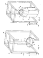
- Figur 1
- eine schematische, perspektivische Darstellung der an einem Rahmengestell befestigten Entleervorrichtung in abgesenktem Zustand ohne Absaugvorrichtung, wobei ein vorderer Stützpfosten des Rahmengestells der besseren Übersichtlichkeit wegen weggeschnitten wurde,
- Figur 2
- eine Figur 1 entsprechende Darstellung mit einem Oktabin mit innenliegendem Foliensack, der das zu entleerende Schüttgut enthält, wobei der Foliensack von der Entleervorrichtung ergriffen und diese in der angehobenen Stellung gezeigt ist,
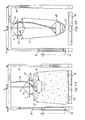
- Figuren 3A und 3B
- teilweise geschnittene Seitenansichten der Entleervorrichtung mit einem Oktabin und einer Absaugvorrichtung, wobei die Positionen zu Beginn bzw. am Ende des Absaugvorganges gezeigt sind, und
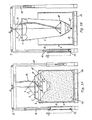
- Figuren 4A und 4B
- eine Darstellung entsprechend den Figuren 3A und 3B, wobei als Behältnis ein Big-Bag mit Henkeln verwendet wird.
- Wie aus Figur 1 ersichtlich, besteht die Entleervorrichtung im wesentlichen aus einem ringförmigen
- Halterahmen 1 aus einem biegefesten Material, beispielsweise Stahl, der über drei Zugelemente in der Form von Seilen 2 an einem Seilzug 3 aufgehängt ist.
- Die Seile 2 weisen die gleiche Länge auf und sind über den Umfang des Halterahmens 1 regelmäßig angeordnet, d. h. mit ihrem unteren Ende am Halterahmen 1 befestigt, während ihre gegenüberliegenden Enden an einer zentralen Verbindungsstelle 4 zusammenlaufen und dort am Seilzug 3 befestigt sind. Diese Dreipunktaufhängung gewährleistet, daß der Halterahmen 1 in statisch bestimmter Weise aufgehängt ist, wobei er in einer horizontalen Ebene liegt.
- Vom Halterahmen 1 aus erstrecken sich acht Klemmelemente 5 für einen in den Figuren 2 bis 3B gezeigten Foliensack 6 nach unten, wobei dieser Foliensack die Innenverkleidung eines Oktabins 7 darstellt, in dem das Schüttmaterial, beispielsweise Kunststoffgranulat, enthalten ist.
- Die Klemmelemente 5 sind regelmäßig über den Umfang des Halterahmens 1 angeordnet, d. h. sie weisen zueinander einen gleichmäßigen Abstand auf, wobei sie schwenkbar am Halterahmen 1 befestigt sind. Die Klemmelemente 5 bestehen im dargestellten Ausführungsbeispiel aus zwei Klemmbacken, zwischen denen der Foliensack 6 in seinem oberen Randbereich eingeführt werden kann, worauf die Klemmbacken zusammengepreßt werden und den Foliensack zwischen sich einklemmen. Um eine sichere Halterung des Foliensackes 6 zwischen den Klemmbacken zu gewährleisten, können diese mit entsprechenden Gummiflächen oder gerippten Flächen versehen sein.
- Der Seilzug 3 ist über Umlenkrollen 8, 9 geführt, die an der Oberseite eines Rahmengestells 10 angeordnet sind.
- Diese Seilzugführung bewirkt, daß der Seilzug 3 zunächst vertikal nach oben zur Oberseite des Rahmengestells 10 und von dort in horizontaler Richtung bis zur Umlenkrolle 9 geführt wird, die sich im Bereich einer oberen Ecke des Rahmengestells 10 befindet. Von der Umlenkrolle 9 aus erstreckt sich der Seilzug 3 wiederum vertikal nach unten und ist an seinem freien Ende an einer Kolbenstange 11 eines Hubzylinders 12 befestigt. Der Hubzylinder 12 kann pneumatisch oder hydraulisch betätigt werden. Alternativ zu einem Hubzylinder ist es auch möglich, andere alternative Hubeinrichtungen wie beispielsweise einen Elektromotor oder eine manuell betätigbare Handkurbel, zu verwenden.
- In Figur 1 ist die Kolbenstange 11 des Hubzylinders 12 voll ausgefahren, so daß sich der Halterahmen 1 mit den daran befestigten Klemmelementen 5, die zusammen ein Hebezeug bilden, sich in ihrer tiefsten Stellung befinden.
- In dieser tiefsten Stellung bzw. in einer nur leicht angehobenen Stellung des Hebezeugs kann der das Schüttgut 13 enthaltende und auf einer Palette 14 stehende Oktabin 7 (Figur 3A) beispielsweise mittels eines Gabelstaplers in das portalartige Rahmengestell 10 eingefahren werden, bis sich der Oktabin 7 mittig unterhalb des Hebezeugs befindet. Anschließend werden die Klemmelemente 5 im oberen Randbereich des Foliensackes 6 festgeklemmt und eine Absaugvorrichtung 15 von oben her in den Foliensack 6 eingeführt. Bei der Absaugvorrichtung 15 kann es sich, wie in den Figuren 3A und 3B dargestellt, um einen an einen Saugschlauch 16 angeschlossenen, schwimmfähigen Absaugkopf 18 oder alternativ hierzu lediglich um ein Absaugrohr handeln, das von oben her wie ein Staubsaugerrohr in den Foliensack 6 eingeführt wird. Das Schüttgut 13 kann nun über den Saugschlauch 16 der Absaugvorrichtung 15 aus dem Foliensack 6 herausgesaugt werden. Da die Absaugvorrichtung 15 als solche bekannt ist, wird diese nicht näher beschrieben.
- Zu Beginn des Entleervorgangs, der in Figur 3A dargestellt ist, ist der Foliensack 6 zumindest weitgehend mit dem Schüttgut 13 gefüllt, so daß er bis in die Nähe des oberen Randbereichs einer starren, achteckigen Außenumhüllung 17 des Oktabins 7 an die Innenumfangswand dieser Außenumhüllung 17 gedrückt wird. Da sich in diesem Anfangsstadium der Halterahmen 1 in einer relativ tiefen Position befindet, ist die Kolbenstange 11 des Hubzylinders 12 relativ weit ausgefahren.
- Während des Absaugens des Schüttgutes 13 wird die Kolbenstange 11 kontinuierlich in das Innere des Hubzylinders 12 eingezogen, wodurch das Hebezeug entsprechend angehoben und der Foliensack 6 nach oben strammgezogen, d. h. gestreckt wird. Da der Halterahmen 1 einen kleineren Durchmesser als der Oktabin 7 aufweist, wird der obere Randbereich des Foliensackes 6 gleichzeitig radial nach innen gezogen. Hierdurch wird das Fließen des Schüttgutes 13 von den Randbereichen des Oktabins 7 zu seiner Mitte hin unterstützt, wo sich der Absaugkopf 18 der Absaugvorrichtung 15 befindet.
- Mit zunehmender Entleerung wird der Foliensack 6 mittels der Hubeinrichtung 12 immer weiter nach oben gezogen, wodurch der Foliensack 6 fortlaufend und zunehmend gestreckt wird.
- Der Zustand der völligen oder zumindest fast völligen Entleerung des Oktabins 7 ist in Figur 3B dargestellt. In diesem Zustand nimmt der Foliensack 6 einen im Verhältnis zur starren Außenumhüllung 17 wesentlich verringerten Durchmesser ein, wobei lediglich im untersten Bereich des Foliensackes 6 eine Restmenge 131 an Schüttgut vorhanden ist. Diese Restmenge 131 befindet sich lediglich unterhalb, nicht jedoch seitlich neben dem Absaugkopf 18, an dem der untere Bereich des Foliensackes 6 seitlich anliegt.
- Im entleerten Zustand des Oktabins 7 ist die Kolbenstange 11 zumindest weitgehend in das Innere des Hubzylinders 12 zurückgezogen, wodurch das Hebezeug soweit angehoben wird, daß der Foliensack 6 geringfügig vom Boden 19 der Oktabin-Außenumhüllung 17 abgehoben ist. Dies zeigt dem Betreiber, daß der Oktabin 7 entleert ist und ausgewechselt werden kann.
- Die Endstellungen des Hubzylinders 12, d. h. die maximalen Ausfahr- und Einzugslängen der Kolbenstange 11, werden zweckmäßigerweise durch geeignete, nicht dargestellte Endschalter bestimmt und sind vorteilhafterweise variabel, um sich an unterschiedliche Behältnishöhen anzupassen.
- Anstelle eines kontinuierlichen Hochziehens des Foliensackes 6 kann dieser auch intermittierend, d. h. stufenweise, hochgezogen werden.
- Ein in den Figuren 3A und 3B weiterhin dargestellter Seilzug 20 dient lediglich dem Gewichtsausgleich für den Absaugkopf 18, damit dieser mit einer vorbestimmten Druckkraft auf dem Schüttgut 13 aufliegt und auf diesem schwimmt. Dieser Gewichtsausgleich wird hier nicht näher beschrieben.
- Bei der in den Figuren 4A und 4B gezeigten alternativen Ausführungsform wird kein Oktabin, sondern ein sog. Big-Bag 6' verwendet, welcher keine starre Außenumhüllung aufweist, sondern lediglich aus einem reifsten Gewebesack besteht. Am oberen Rand des Big-Bags 61 sind vier Henkel 20 vorgesehen, die zum Transport dienen.
- Die in den Figuren 4A und 4B gezeigte alternative Ausführungsform der Entleervorrichtung unterscheidet sich von derjenigen der Figuren 1 bis 3B nur dadurch, daß anstelle der Klemmelemente 5 Haken 21 am Halterahmen 1 befestigt sind, die in die Henkel 20 eingreifen, um den Big-Bag 61 während des Entleerens des Schüttgutes 13 in entsprechender Weise hochzuziehen. Die übrige Ausgestaltung und Funktionsweise dieser Entleervorrichtung ist identisch zu der erstgenannten Ausführungsform.
Claims (5)
- Verfahren zum Entleeren von rieselfähigem Schüttgut (13), aus flexiblen, insbesondere sack- oder beutelartigen Behältnissen (6, 6') mittels einer Absaugvorrichtung (15), wobei- die Absaugvorrichtung (15) von oben her in das Behältnis (6, 6') eingeführt wird,- ein Hebezeug (1; 5, 21), umfassend einen ringförmigen oder mehreckigen Halterahmen (1), an dem die Halteelemente (5, 21) befestigt sind und der einen kleineren Durchmesser als das Behältnis (6, 6') aufweist, mit dem oberen Randbereich des Behältnisses (6, 6') in Halteeingriff gebracht wird,- das Hebezeug (1; 5, 21) mittels einer Hubeinrichtung (12) in vertikaler Richtung bewegt wird, um das Behältnis (6, 6') zu strecken,- wobei der obere Randbereich des Behältnisses (6, 6') beim Hochziehen radial nach innen gezogen wird,dadurch gekennzeichnet, daß
gegen Ende des Entleerungsvorganges das gesamte Behältnis (6, 6') mit dem Schüttgutrest vom Boden weggehoben wird. - Verfahren nach Anspruch 1,
dadurch gekennzeichnet, daß
die Hubeinrichtung (12) eine Zugkraft auf das Behältnis (6, 6') ausübt, welche größer als die Gewichtskraft der Absaugvorrichtung (15) und des restlichen Schüttguts gegen Ende des Entleervorganges, jedoch geringer als die Reißfestigkeit des Materials des Behältnisses (6, 6') ist. - Verfahren nach Anspruch 1 oder 2,
dadurch gekennzeichnet, daß
das Hochheben des Behältnisses (6, 6') als Signal für das fast vollständige Entleeren des Behältnisses (6, 6') dient. - Verfahren zum Entleeren von rieselfähigem Schüttgut (13), aus flexiblen, insbesondere sack- oder beutelartigen Behältnissen (6, 6') mittels einer Absaugvorrichtung (15) mit einem Absaugkopf (18), wobei- die Absaugvorrichtung (15) von oben her in das Behältnis (6, 6') eingeführt wird,- ein Hebezeug (1; 5, 21), umfassend einen ringförmigen oder mehreckigen Halterahmen (1), an dem die Halteelemente (5, 21) befestigt sind und der einen kleineren Durchmesser als das Behältnis (6, 6') aufweist, mit dem oberen Randbereich des Behältnisses (6, 6') in Halteeingriff gebracht wird,- das Hebezeug (1; 5, 21) mittels einer Hubeinrichtung (12) in vertikaler Richtung bewegt wird, um das Behältnis (6, 6') zu strecken,- wobei der obere Randbereich des Behältnisses (6, 6') beim Hochziehen radial nach innen gezogen wird,dadurch gekennzeichnet, daß
mit zunehmender Entleerung das Behältnis (6, 6') immer weiter nach oben gezogen und zunehmend gestreckt wird, bis der untere Bereich des Behältnisses (6, 6') seitlich am Absaugkopf (18) der Absaugvorrichtung (15) anliegt und dabei das gesamte Behältnis (6, 6') mit dem Schüttgutrest vom Boden weggehoben ist. - Verfahren nach Anspruch 4,
dadurch gekennzeichnet, daß
das Hochziehen und Strecken des Behältnisses (6, 6') so lange erfolgt, bis die Restmenge (13') des Schüttgutes (13) sich lediglich unterhalb, nicht jedoch seitlich des Absaugkopfes (18) im Behältnis (6, 6') befindet.
Priority Applications (1)
| Application Number | Priority Date | Filing Date | Title |
|---|---|---|---|
| DE29724370U DE29724370U1 (de) | 1996-07-15 | 1997-07-10 | Entleervorrichtung für rieselfähiges Schüttgut |
Applications Claiming Priority (2)
| Application Number | Priority Date | Filing Date | Title |
|---|---|---|---|
| DE19628429A DE19628429C2 (de) | 1996-07-15 | 1996-07-15 | Entleervorrichtung für rieselfähiges Schüttgut |
| DE19628429 | 1996-07-15 |
Publications (3)
| Publication Number | Publication Date |
|---|---|
| EP0819628A1 EP0819628A1 (de) | 1998-01-21 |
| EP0819628B1 EP0819628B1 (de) | 2001-05-23 |
| EP0819628B2 true EP0819628B2 (de) | 2007-01-03 |
Family
ID=7799840
Family Applications (1)
| Application Number | Title | Priority Date | Filing Date |
|---|---|---|---|
| EP97111769A Expired - Lifetime EP0819628B2 (de) | 1996-07-15 | 1997-07-10 | Verfahren zum Entleeren von Schüttgut |
Country Status (5)
| Country | Link |
|---|---|
| US (1) | US5944455A (de) |
| EP (1) | EP0819628B2 (de) |
| AT (1) | ATE201377T1 (de) |
| DE (2) | DE19628429C2 (de) |
| ES (1) | ES2158410T5 (de) |
Families Citing this family (24)
| Publication number | Priority date | Publication date | Assignee | Title |
|---|---|---|---|---|
| DE19733812A1 (de) * | 1997-08-05 | 1999-02-11 | Ekkehard Steinecke | Behälter für Schüttgut |
| DE19741108A1 (de) * | 1997-09-18 | 1999-03-25 | Delta P Vakuum Und Niederdruck | Vorrichtung zum Entleeren von rieselfähigem Schüttgut |
| WO1999016691A1 (en) * | 1997-09-30 | 1999-04-08 | Minnesota Mining And Manufacturing Company | Particulate transfer system for transferring particulate and a method of use |
| DE29803071U1 (de) | 1998-02-23 | 1998-05-20 | Sandi, Roland, Meggen | Automatisierte Sackentleerungsstation |
| DE19852259C2 (de) * | 1998-11-13 | 2001-08-16 | Wilhelm Nikolaus | Entleervorrichtung für rieselfähiges Schüttgut |
| DE10051400A1 (de) * | 2000-10-17 | 2002-05-02 | Klaus Wilhelm | Verfahren und Vorrichtung zum Entleeren von Schüttgut |
| FR2818261B1 (fr) * | 2000-12-19 | 2003-02-21 | Dietrich Yves | Installation de vidange de futs et procede d'utilisation de ladite installation |
| US7025318B2 (en) * | 2001-03-19 | 2006-04-11 | Baxter International Inc. | Container support |
| GB2378431A (en) * | 2001-06-07 | 2003-02-12 | Jeremy James Cathcart | Apparatus for handling bulk material. |
| DE10211256A1 (de) * | 2002-03-13 | 2003-10-09 | Bernd Johanningmann | Vorrichtung zur dosierten Abgabe von Schüttgut |
| US7284579B2 (en) * | 2003-03-28 | 2007-10-23 | Hyclone Laboratories, Inc. | Fluid dispensing bins and related methods |
| US6979166B2 (en) * | 2003-05-15 | 2005-12-27 | Kellogg Company | Vacuum wand assembly for extracting a product from a container |
| CA2559496A1 (en) | 2004-04-27 | 2005-11-17 | Baxter International Inc. | Stirred-tank reactor system |
| US7963728B2 (en) * | 2006-01-06 | 2011-06-21 | Valspar Sourcing, Inc. | Method and apparatus for powder delivery system |
| JP5567009B2 (ja) | 2008-06-05 | 2014-08-06 | ケロッグ カンパニー | ばら荷用可搬容器を製造するための方法 |
| US8104520B2 (en) | 2008-06-11 | 2012-01-31 | Kellogg Company | Gentle handling hopper and scrunched bag for filling and forming a transportable container |
| ES2960158T3 (es) * | 2008-09-03 | 2024-02-29 | Kellog Co | Procedimiento para la formación de un contenedor transportable de mercancías a granel |
| MX337810B (es) | 2010-12-01 | 2016-03-18 | Kellog Co | Contenedor transportable para articulos a granel y metodo para formarlo. |
| WO2014009889A1 (en) * | 2012-07-13 | 2014-01-16 | Moretto S.P.A. | An emptying device for storage containers of granular materials or the like |
| JP6251542B2 (ja) * | 2013-10-29 | 2017-12-20 | 赤武エンジニアリング株式会社 | フレコンバッグの粉体の吸引取出装置 |
| US20150135643A1 (en) * | 2013-11-15 | 2015-05-21 | Conecraft, Inc. | Bag Lift Assembly for a Lined Bulk Material Container |
| DE102014200452B4 (de) * | 2014-01-13 | 2025-03-27 | Hecht Technologie Gmbh | Entleerungseinrichtung |
| EP2937145B1 (de) * | 2014-04-24 | 2017-06-07 | Robatech AG | Einrichtung zum Fördern eines feinteiligen Mediums |
| CN104261319A (zh) * | 2014-09-16 | 2015-01-07 | 昆山恒诚荣机械设备有限公司 | 吨包清料装置 |
Family Cites Families (9)
| Publication number | Priority date | Publication date | Assignee | Title |
|---|---|---|---|---|
| DE624645C (de) * | 1936-02-22 | Friedrich Endres | Silo fuer Getreide und aehnliches koerniges Schuettgut | |
| DE1531920A1 (de) * | 1967-10-05 | 1970-01-15 | Eisgruber Karl Heinrich | Siloanlage |
| BE755420A (fr) * | 1969-08-29 | 1971-02-01 | Bennigsen Mackiewicz A Von | Cuve en matiere flexible pour marchandise en vrac, en particulier pour farine |
| JPS63306126A (ja) * | 1987-06-05 | 1988-12-14 | Akiyoshi Kondo | 穀類散積運搬方法 |
| DE4218331C2 (de) * | 1992-06-04 | 2003-01-02 | Oswald Metzen Gmbh Industriete | Vorrichtung zur Entleerung von Schüttgutbehältern |
| DE4315327A1 (de) | 1993-05-01 | 1994-11-03 | Farb Tec Beschichtung | Verfahren zum Fördern von in flexiblen Behältnissen gelagertem pulverartigem Material |
| US5382117A (en) * | 1994-03-28 | 1995-01-17 | Henkel Kommanditgesellschaft Auf Aktien | Apparatus for holding a powder container |
| DE29515675U1 (de) * | 1995-10-02 | 1995-11-30 | Fritz, Walter, 85232 Bergkirchen | Absaugvorrichtung für Schüttgutbehälter |
| DE29612187U1 (de) * | 1996-07-15 | 1996-08-29 | Wilhelm, Klaus, 83022 Rosenheim | Entleervorrichtung für rieselfähiges Schüttgut |
-
1996
- 1996-07-15 DE DE19628429A patent/DE19628429C2/de not_active Expired - Fee Related
-
1997
- 1997-07-08 US US08/889,626 patent/US5944455A/en not_active Expired - Fee Related
- 1997-07-10 AT AT97111769T patent/ATE201377T1/de active
- 1997-07-10 ES ES97111769T patent/ES2158410T5/es not_active Expired - Lifetime
- 1997-07-10 EP EP97111769A patent/EP0819628B2/de not_active Expired - Lifetime
- 1997-07-10 DE DE59703584T patent/DE59703584D1/de not_active Expired - Lifetime
Also Published As
| Publication number | Publication date |
|---|---|
| US5944455A (en) | 1999-08-31 |
| ES2158410T3 (es) | 2001-09-01 |
| ATE201377T1 (de) | 2001-06-15 |
| EP0819628B1 (de) | 2001-05-23 |
| ES2158410T5 (es) | 2007-09-01 |
| DE19628429A1 (de) | 1997-01-16 |
| DE19628429C2 (de) | 1999-03-11 |
| DE59703584D1 (de) | 2001-06-28 |
| EP0819628A1 (de) | 1998-01-21 |
Similar Documents
| Publication | Publication Date | Title |
|---|---|---|
| EP0819628B2 (de) | Verfahren zum Entleeren von Schüttgut | |
| EP1349788B1 (de) | Vorrichtung für gro volumige behältnisse | |
| EP0835829B1 (de) | Entleerungsvorrichtung für Bulk-Bags und deren Verwendung | |
| DE2851184C2 (de) | Vorrichtung zum Füllen eines Behälters in staubfreiem Betrieb | |
| EP0943560B1 (de) | Automatisierte Sackentleerungsstation | |
| DE2149351A1 (de) | Muellverdichtungsvorrichtung | |
| EP0188478A1 (de) | Vorrichtung zum befüllen flexibler schüttgutbehälter. | |
| EP3045375A1 (de) | Vertikal-Hubwagen | |
| DE2151116A1 (de) | Verfahren und vorrichtung zur luftdichten flachlagerung von guetern | |
| EP1199266B1 (de) | Verfahren und Vorrichtung zum Entleeren von Schüttgut | |
| DE2947872A1 (de) | Absackvorrichtung | |
| DE29612187U1 (de) | Entleervorrichtung für rieselfähiges Schüttgut | |
| EP1580133A2 (de) | Verfahren und Vorrichtung zum Entleeren von Schüttgut | |
| DE69605231T2 (de) | Vorrichtung zum Verpacken von Produkten in Beuteln, ausgehend von einem Vorrat von schlauchförmigem Netz | |
| DE10013838C2 (de) | Andockvorrichtung zum staubfreien Anschließen eines Big Bag | |
| DE20209351U1 (de) | Vorrichtung zum Handhaben von rieselfähigen Baustoffen | |
| DE9418696U1 (de) | Vorrichtung zum Anheben und Entleeren von Recyclingbehältern | |
| DE69819530T2 (de) | Verfahren und vorrichtung zum presspacken von bäumen und strauchwerk auf paletten mit seitenränden | |
| DE29724370U1 (de) | Entleervorrichtung für rieselfähiges Schüttgut | |
| DE2848505A1 (de) | Vorrichtung zum abfuellen von hochvoluminoesen pulverfoermigen stoffen in staubdichte behaelter | |
| DE202009005174U1 (de) | Fest-Flüssig-Anhänger | |
| DE69606219T2 (de) | Verfahren zum Verpacken von Produkten in Beuteln, ausgehend von einem Vorrat von schlauchförmigem Netz | |
| EP2881340B1 (de) | Verfahren zum Befüllen eines 20 Fuss Containers | |
| DE10251980A1 (de) | Vorrichtung zum Stützen eines Materialsacks | |
| DE102018120429A1 (de) | Packvorrichtung zum Presspacken von Bäumen |
Legal Events
| Date | Code | Title | Description |
|---|---|---|---|
| PUAI | Public reference made under article 153(3) epc to a published international application that has entered the european phase |
Free format text: ORIGINAL CODE: 0009012 |
|
| AK | Designated contracting states |
Kind code of ref document: A1 Designated state(s): AT BE CH DE DK ES FI FR GB IT LI NL SE |
|
| 17P | Request for examination filed |
Effective date: 19971127 |
|
| AKX | Designation fees paid |
Free format text: AT BE CH DE DK ES FI FR GB IT LI NL SE |
|
| RBV | Designated contracting states (corrected) |
Designated state(s): AT BE CH DE DK ES FI FR GB IT LI NL SE |
|
| 17Q | First examination report despatched |
Effective date: 19991202 |
|
| GRAG | Despatch of communication of intention to grant |
Free format text: ORIGINAL CODE: EPIDOS AGRA |
|
| GRAG | Despatch of communication of intention to grant |
Free format text: ORIGINAL CODE: EPIDOS AGRA |
|
| GRAH | Despatch of communication of intention to grant a patent |
Free format text: ORIGINAL CODE: EPIDOS IGRA |
|
| TPAD | Observations filed by third parties |
Free format text: ORIGINAL CODE: EPIDOS TIPA |
|
| GRAH | Despatch of communication of intention to grant a patent |
Free format text: ORIGINAL CODE: EPIDOS IGRA |
|
| GRAA | (expected) grant |
Free format text: ORIGINAL CODE: 0009210 |
|
| AK | Designated contracting states |
Kind code of ref document: B1 Designated state(s): AT BE CH DE DK ES FI FR GB IT LI NL SE |
|
| PG25 | Lapsed in a contracting state [announced via postgrant information from national office to epo] |
Ref country code: NL Free format text: LAPSE BECAUSE OF FAILURE TO SUBMIT A TRANSLATION OF THE DESCRIPTION OR TO PAY THE FEE WITHIN THE PRESCRIBED TIME-LIMIT Effective date: 20010523 Ref country code: FI Free format text: LAPSE BECAUSE OF FAILURE TO SUBMIT A TRANSLATION OF THE DESCRIPTION OR TO PAY THE FEE WITHIN THE PRESCRIBED TIME-LIMIT Effective date: 20010523 |
|
| REF | Corresponds to: |
Ref document number: 201377 Country of ref document: AT Date of ref document: 20010615 Kind code of ref document: T |
|
| REG | Reference to a national code |
Ref country code: CH Ref legal event code: EP |
|
| REG | Reference to a national code |
Ref country code: CH Ref legal event code: NV Representative=s name: SCHMAUDER & PARTNER AG PATENTANWALTSBUERO * SCHMAU |
|
| ITF | It: translation for a ep patent filed | ||
| GBT | Gb: translation of ep patent filed (gb section 77(6)(a)/1977) |
Effective date: 20010605 |
|
| REF | Corresponds to: |
Ref document number: 59703584 Country of ref document: DE Date of ref document: 20010628 |
|
| PG25 | Lapsed in a contracting state [announced via postgrant information from national office to epo] |
Ref country code: BE Free format text: LAPSE BECAUSE OF NON-PAYMENT OF DUE FEES Effective date: 20010731 |
|
| PG25 | Lapsed in a contracting state [announced via postgrant information from national office to epo] |
Ref country code: SE Free format text: LAPSE BECAUSE OF FAILURE TO SUBMIT A TRANSLATION OF THE DESCRIPTION OR TO PAY THE FEE WITHIN THE PRESCRIBED TIME-LIMIT Effective date: 20010823 Ref country code: DK Free format text: LAPSE BECAUSE OF FAILURE TO SUBMIT A TRANSLATION OF THE DESCRIPTION OR TO PAY THE FEE WITHIN THE PRESCRIBED TIME-LIMIT Effective date: 20010823 |
|
| REG | Reference to a national code |
Ref country code: ES Ref legal event code: FG2A Ref document number: 2158410 Country of ref document: ES Kind code of ref document: T3 |
|
| NLV1 | Nl: lapsed or annulled due to failure to fulfill the requirements of art. 29p and 29m of the patents act | ||
| ET | Fr: translation filed | ||
| REG | Reference to a national code |
Ref country code: GB Ref legal event code: IF02 |
|
| BERE | Be: lapsed |
Owner name: WILHELM KLAUS Effective date: 20010731 |
|
| PLBQ | Unpublished change to opponent data |
Free format text: ORIGINAL CODE: EPIDOS OPPO |
|
| PLBI | Opposition filed |
Free format text: ORIGINAL CODE: 0009260 |
|
| PLBF | Reply of patent proprietor to notice(s) of opposition |
Free format text: ORIGINAL CODE: EPIDOS OBSO |
|
| 26 | Opposition filed |
Opponent name: AROLIT-PLASTIC GMBH Effective date: 20020222 |
|
| PLBF | Reply of patent proprietor to notice(s) of opposition |
Free format text: ORIGINAL CODE: EPIDOS OBSO |
|
| PLAY | Examination report in opposition despatched + time limit |
Free format text: ORIGINAL CODE: EPIDOSNORE2 |
|
| PLAY | Examination report in opposition despatched + time limit |
Free format text: ORIGINAL CODE: EPIDOSNORE2 |
|
| PLBC | Reply to examination report in opposition received |
Free format text: ORIGINAL CODE: EPIDOSNORE3 |
|
| APBP | Date of receipt of notice of appeal recorded |
Free format text: ORIGINAL CODE: EPIDOSNNOA2O |
|
| APBM | Appeal reference recorded |
Free format text: ORIGINAL CODE: EPIDOSNREFNO |
|
| APBQ | Date of receipt of statement of grounds of appeal recorded |
Free format text: ORIGINAL CODE: EPIDOSNNOA3O |
|
| APAH | Appeal reference modified |
Free format text: ORIGINAL CODE: EPIDOSCREFNO |
|
| APBU | Appeal procedure closed |
Free format text: ORIGINAL CODE: EPIDOSNNOA9O |
|
| RTI2 | Title (correction) |
Free format text: PROCESS OF EMPTYING OF POURABLE MATERIAL |
|
| PUAH | Patent maintained in amended form |
Free format text: ORIGINAL CODE: 0009272 |
|
| STAA | Information on the status of an ep patent application or granted ep patent |
Free format text: STATUS: PATENT MAINTAINED AS AMENDED |
|
| 27A | Patent maintained in amended form |
Effective date: 20070103 |
|
| AK | Designated contracting states |
Kind code of ref document: B2 Designated state(s): AT BE CH DE DK ES FI FR GB IT LI NL SE |
|
| GBTA | Gb: translation of amended ep patent filed (gb section 77(6)(b)/1977) | ||
| ET3 | Fr: translation filed ** decision concerning opposition | ||
| REG | Reference to a national code |
Ref country code: ES Ref legal event code: DC2A Date of ref document: 20070323 Kind code of ref document: T5 |
|
| REG | Reference to a national code |
Ref country code: CH Ref legal event code: PCAR Free format text: SCHMAUDER & PARTNER AG PATENT- UND MARKENANWAELTE VSP;ZWAENGIWEG 7;8038 ZUERICH (CH) |
|
| PGFP | Annual fee paid to national office [announced via postgrant information from national office to epo] |
Ref country code: DE Payment date: 20110728 Year of fee payment: 15 |
|
| REG | Reference to a national code |
Ref country code: DE Ref legal event code: R042 Ref document number: 59703584 Country of ref document: DE Effective date: 20111117 |
|
| PG25 | Lapsed in a contracting state [announced via postgrant information from national office to epo] |
Ref country code: DE Free format text: THE PATENT HAS BEEN ANNULLED BY A DECISION OF A NATIONAL AUTHORITY Effective date: 20111117 |
|
| REG | Reference to a national code |
Ref country code: FR Ref legal event code: PLFP Year of fee payment: 19 |
|
| PGFP | Annual fee paid to national office [announced via postgrant information from national office to epo] |
Ref country code: GB Payment date: 20150724 Year of fee payment: 19 Ref country code: ES Payment date: 20150723 Year of fee payment: 19 |
|
| PGFP | Annual fee paid to national office [announced via postgrant information from national office to epo] |
Ref country code: FR Payment date: 20150730 Year of fee payment: 19 Ref country code: AT Payment date: 20150722 Year of fee payment: 19 |
|
| PGFP | Annual fee paid to national office [announced via postgrant information from national office to epo] |
Ref country code: IT Payment date: 20150728 Year of fee payment: 19 |
|
| PGFP | Annual fee paid to national office [announced via postgrant information from national office to epo] |
Ref country code: CH Payment date: 20160726 Year of fee payment: 20 |
|
| REG | Reference to a national code |
Ref country code: AT Ref legal event code: MM01 Ref document number: 201377 Country of ref document: AT Kind code of ref document: T Effective date: 20160710 |
|
| GBPC | Gb: european patent ceased through non-payment of renewal fee |
Effective date: 20160710 |
|
| PG25 | Lapsed in a contracting state [announced via postgrant information from national office to epo] |
Ref country code: FR Free format text: LAPSE BECAUSE OF NON-PAYMENT OF DUE FEES Effective date: 20160801 |
|
| REG | Reference to a national code |
Ref country code: FR Ref legal event code: ST Effective date: 20170331 |
|
| PG25 | Lapsed in a contracting state [announced via postgrant information from national office to epo] |
Ref country code: AT Free format text: LAPSE BECAUSE OF NON-PAYMENT OF DUE FEES Effective date: 20160710 Ref country code: GB Free format text: LAPSE BECAUSE OF NON-PAYMENT OF DUE FEES Effective date: 20160710 |
|
| REG | Reference to a national code |
Ref country code: CH Ref legal event code: PL |
|
| PG25 | Lapsed in a contracting state [announced via postgrant information from national office to epo] |
Ref country code: IT Free format text: LAPSE BECAUSE OF NON-PAYMENT OF DUE FEES Effective date: 20160710 |
|
| REG | Reference to a national code |
Ref country code: ES Ref legal event code: FD2A Effective date: 20180507 |
|
| PG25 | Lapsed in a contracting state [announced via postgrant information from national office to epo] |
Ref country code: ES Free format text: LAPSE BECAUSE OF NON-PAYMENT OF DUE FEES Effective date: 20160711 |