EP0818275B1 - Setzgerät mit Transportvorrichtung für streifenförmige Magazine - Google Patents
Setzgerät mit Transportvorrichtung für streifenförmige Magazine Download PDFInfo
- Publication number
- EP0818275B1 EP0818275B1 EP97810251A EP97810251A EP0818275B1 EP 0818275 B1 EP0818275 B1 EP 0818275B1 EP 97810251 A EP97810251 A EP 97810251A EP 97810251 A EP97810251 A EP 97810251A EP 0818275 B1 EP0818275 B1 EP 0818275B1
- Authority
- EP
- European Patent Office
- Prior art keywords
- armed
- lever
- feeder
- transport
- arm
- Prior art date
- Legal status (The legal status is an assumption and is not a legal conclusion. Google has not performed a legal analysis and makes no representation as to the accuracy of the status listed.)
- Expired - Lifetime
Links
Images

Classifications
-
- B—PERFORMING OPERATIONS; TRANSPORTING
- B25—HAND TOOLS; PORTABLE POWER-DRIVEN TOOLS; MANIPULATORS
- B25C—HAND-HELD NAILING OR STAPLING TOOLS; MANUALLY OPERATED PORTABLE STAPLING TOOLS
- B25C1/00—Hand-held nailing tools; Nail feeding devices
- B25C1/001—Nail feeding devices
- B25C1/003—Nail feeding devices for belts of nails
-
- B—PERFORMING OPERATIONS; TRANSPORTING
- B25—HAND TOOLS; PORTABLE POWER-DRIVEN TOOLS; MANIPULATORS
- B25B—TOOLS OR BENCH DEVICES NOT OTHERWISE PROVIDED FOR, FOR FASTENING, CONNECTING, DISENGAGING, OR HOLDING
- B25B23/00—Details of, or accessories for, spanners, wrenches, screwdrivers
- B25B23/02—Arrangements for handling screws or nuts
- B25B23/04—Arrangements for handling screws or nuts for feeding screws or nuts
- B25B23/045—Arrangements for handling screws or nuts for feeding screws or nuts using disposable strips or discs carrying the screws or nuts
Definitions
- the invention relates to a setting tool with a transport device according to the preamble of claim 1.
- a setting device with a transport device for strip-shaped Magazines known, on which spaced apart fasteners are arranged.
- the transport device has a housing opposite the Setting tool, as well as a guide channel that can be moved parallel to the setting direction having attachment and a two-armed pivotally arranged on the attachment Transport lever open.
- On a first lever arm of the two-armed transport lever there is one with a magazine arranged in the guide channel interacting, swiveling pawl.
- the second lever arm works with one Control curve of the housing together. A swiveling of the two-armed Transport lever in the transport direction takes place when the setting tool against a surface is pressed and the attachment moves towards the housing.
- the transport device of this known setting tool is due to the constructive Interpretation only capable of a single, uniform, predetermined transport route ensure. A change in this constructively predetermined transport route is not possible.
- the object of the invention is a for a setting tool of the type mentioned Transport device to create the different transport routes without manual Intervention allows.
- the one-armed transport lever enables a first magazine to be transported subsequent magazine inserted into the guide channel. Is only one first magazine in the guide channel, this first magazine is transported via the two-armed transport lever. There is another, the first magazine subsequent magazine in the guide channel, so both magazines are transported through the one-armed transport lever as soon as this with the first Fastening element of the following magazine interacts.
- the problem may arise reveal that the distance between the last fastener of the first Magazine and the first fastener of the second magazine is larger than that Transport route of the two-armed transport lever. So that the one-armed transport lever with the first fastener of subsequent magazine can work together, it must be a larger one Have transport path than the two-armed transport lever.
- the different transport routes of the two transport levers are determined using a Achieved transmission element, which is formed by a slide.
- the Transport of both magazines in the guide channel by a path that corresponds to the transport path of the two-armed transport lever.
- the pressure path of the setting tool For example is larger than the transport path of the second transport lever, the Excess pressure path can be compensated for by the transport device.
- the housing arranged a transport arm with a bearing surface, the compared to the one-armed transport lever is displaceable by a path that corresponds at least to the transport path of the two-armed transport lever.
- the spring force of the spring element is greater than the spring force of the Feather.
- the setting tool is removed from the surface after a pressing process lifted off without the fastener in the set position Drive underground, then in the subsequent pressing process Do not move magazines in the guide channel in the transport direction so that that transmitted from a stop surface of the housing to the transport device
- the pressure path must be fully compensated without the transport levers offset. At least part of the contact path is covered with the support surface compensated, which can be moved one way in relation to the transport arm in the setting direction which corresponds at least to the transport path of the two-armed transport lever.
- the pressing path of the setting tool corresponds to the double transport path of the two-armed transport lever, half the contact distance between the Transport arm and the one-armed transport lever compensated.
- the Spring force of the compression spring is greater than the spring force of the spring element.
- the magazine can be transported properly in the guide channel can, preferably corresponds to the transport path of the two-armed transport lever Distance between two adjacent, on the strip-shaped magazine arranged fasteners.
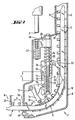
- the setting tool shown in Fig. 1 has a housing 1 to which a guide tube 3 connects in the setting direction. Opposite this guide tube 3 is a cylindrical guide part 4 against the setting direction against the force of a arranged between the housing 1 and the cylindrical guide part 4 Positioning spring 5 can be moved.
- On the face of the The guide part 4 is followed by a base plate 6 on which a transport device 7 is attached.
- This transport device is actuated by means of a Housing protruding in the setting direction of the abutment surface 2, which against a support surface 28th presses inside the transport device when the setting tool is not against you shown underground is pressed.
- There is a transfer of the Transport device 7, the base plate 6 and the cylindrical guide part 4 In Towards housing 1 of the setting tool.
- a free end protrudes from the attachment 8 Guide shaft 25, along which a transport arm arranged in the interior of the attachment 26 is displaceable.
- the transport device 7 shown in FIG. 2 has an attachment 8 with a Inlet opening 31 and an outlet opening 32.
- the attachment 8 is detachably arranged on the base plate 6 shown in FIG. 1.
- a that Interior of the attachment 8 penetrating guide channel 10 runs in the area of Inlet opening 31 substantially parallel to the longitudinal axis of the setting tool and in Region of the outlet opening 32 substantially perpendicular to the longitudinal axis of the Setting tool.
- the guide channel 10 serves to hold strip-shaped magazines 11, which several bolt-shaped fasteners 12 at a distance A are arranged one behind the other.
- the better insertion of these magazines 11 into one Guide channel 10 serve insertion aids in the form of relatively long areas with surfaces inclined towards the free end of the magazine 11.
- the distance between a free end of the magazine 11 and the nearest fastener in the present embodiment the same size as the distance A between two the fastening elements 12 arranged adjacent to the magazine 11.
- a two-armed transport lever 13 is pivotable on Attachment 8 arranged.
- a first lever arm 14 there is one with a strip-shaped magazine 11 or with one of the fastening elements 12 cooperating, pivotable pawl 16. That end region of this pawl 16 that does not cooperate with the magazine 11 or fastening element 12, is based on a control curve of the header 8.
- a slide-like transmission element 17 is fastened to a second lever arm 15, which is provided with a slot-like guide opening 18 by a stop 19 of a guide block 20 is penetrated.
- the guide block 20 is along one Guide profile 21 of the attachment 8 in the setting direction against the force of one Attachment 8 supporting spring 23 displaceable.
- a pivotable, one-armed Transport lever 22 is arranged at one of the inlet opening 31 facing end region of this guide block 20 arranged.
- the guide block 20 is partially closed in the Guide block 20 projecting on the attachment 8 attached guide shaft 25, which surround is of a spring element 24.
- a transport arm 26 displaceable, which is in the setting direction on the spring element 24 on the guide block 20 supports.
- the support surface 28 is located within the transport arm 26 is also supported in the setting direction on the transport arm 26 via a compression spring 27.
- the stop surface 2 of the housing 1 presses against the Support surface 28 of the transport arm 26, so that it along the guide shaft 25 In Setting direction is shifted.
- the movement of the Transfer arm 26 to the guide block 20 without the spring element 24 is compressed.
- the between the guide block 20 and the header 8th arranged spring 23 is biased.
- the spring force of the spring 23 is lower than the spring force of the spring element 24.
- the guide block 20 passes through with the Stop 19, the slot-like guide opening 18 of the second lever arm 15 of the two-armed transport lever 13 arranged transmission element 17.
- the length L the guide opening 18 corresponds in the example shown to the diameter of the Stop 19 and the distance A between two arranged on the magazine 11, mutually adjacent fasteners 12.
- the two-armed transport lever 13 Due to the free displaceability of the stop 19 in the guide opening 18, the two-armed transport lever 13 only offset when the stop 19 on end of the guide opening 18 on the setting direction side. So that the two-armed Transport lever 13 can also be offset by the amount of the distance A and thus the further fastening element 12 to be transported on the stop edge 30 the base plate 6 can strike, it is necessary that the pressing path at this Embodiment must correspond to at least twice the distance A.
- the stop surface 2 of the housing 1 presses against the Transport arm 26 arranged support surface 28.
- Movement of the stop surface 2 on the transport arm 26 which along the Guide shaft 25 is moved in the setting direction, transmitted.
- the transfer of the Movement of the transport arm 26 on the guide block 20 and thus on the one-armed transport lever 22 takes place by means of a spring element 24 until again a fastening element 12 on the stop edge 30 of the base plate 6 strikes. Since the pressure path of the setting tool is greater than the path by which Fastener 12 is transported, the rest of the compensation Contact path by the spring element 24 can be compressed, so that the transport arm 26 can be moved to the guide block 20.
- Both magazines 11 are transported by the one arranged on the guide block 20 one-armed transport lever 22.
- a pivotable pawl 29 is arranged a displacement of the magazine 11 against the transport direction prevented.
Landscapes
- Engineering & Computer Science (AREA)
- Mechanical Engineering (AREA)
- Portable Nailing Machines And Staplers (AREA)
- Perforating, Stamping-Out Or Severing By Means Other Than Cutting (AREA)
- Automatic Tool Replacement In Machine Tools (AREA)
- Automatic Assembly (AREA)
Description
- Fig. 1
- den setzrichtungsseitigen, vorderen Bereich eines Setzgerätes;
- Fig. 2.
- einen Längsschnitt durch die Transportvorrichtung des Setzgerätes gemäss Fig. 1.
Claims (6)
- Setzgerät mit Transportvorrichtung (7) für streifenförmige Magazine (11) mit im Abstand (A) voneinander angeordneten Befestigungselementen (12), mit einem gegenüber einem Gehäuse (1) parallel zur Setzrichtung versetzbaren, einen Führungskanal (10) aufweisenden Vorsatz (8), einem schwenkbar am Vorsatz (8) angeordneten, zweiarmigen Transporthebel (13), an dessen erstem Hebelarm (14) eine mit dem Magazin (11) zusammenwirkende, schwenkbare Klinke (16) angeordnet ist und dessen zweiter Hebelarm (15) mit einer Anschlagfläche (2) des Gehäuses (1) zusammenwirkt, dadurch gekennzeichnet, dass zwischen der Anschlagfläche (2) des Gehäuses (1) sowie dem zweiten Hebelarm (15) des zweiarmigen Transporthebels (13) ein am Vorsatz (8) angeordneter, gegen die Kraft einer Feder (23) in Setzrichtung versetzbarer, schwenkbarer, einarmiger Transporthebel (22) angeordnet ist, dass zwischen dem einarmigen Transporthebel (22) und dem zweiarmigen Transporthebel (13) ein Schieber (17) angeordnet ist, dessen erster Endbereich mit dem zweiten Hebelarm (15) des zweiarmigen Transporthebels (13) verbunden ist und dessen zweiter Endbereich eine langlochartig ausgebildete, von einem Anschlag (19) des einarmigen Transporthebels (22) durchsetzte Führung (18) aufweist und dass der Schieber (17) gegenüber wenigstens einem der beiden Transporthebel (13, 22) um einen Weg versetzbar ist, der mindestens dem Transportweg des zweiarmigen Transporthebels (13) entspricht.
- Setzgerät nach Anspruch 1 dadurch gekennzeichnet, dass zwischen dem einarmigen Transporthebel (22) und der Anschlagfläche (2) des Gehäuses (1) ein mit einer Auflagefläche (28) versehener Transportarm (26) angeordnet ist, der gegenüber dem einarmigen Transporthebel (22) um einen Weg versetzbar ist, der mindestens dem Transportweg des zweiarmigen Transporthebels (13) entspricht.
- Setzgerät nach Anspruch 2, dadurch gekennzeichnet, dass sich der Transportarm (26) an dem einarmigen Transporthebel (22) über ein Federelement (24) abstützt, dessen Federkraft grösser ist als die Federkraft der Feder (23).
- Setzgerät nach Anspruch 2 oder 3, dadurch gekennzeichnet, dass die an dem Transportarm (26) angeordnete Auflagefläche (28) gegenüber dem einarmigen Transportelement (22) in Setzrichtung um einen Weg versetzbar ist, der mindestens dem Transportweg des zweiarmigen Transporthebels (13) entspricht.
- Setzgerät nach einem der Ansprüche 2 bis 4, dadurch gekennzeichnet, dass sich die Auflagefläche (28) am Transportarm (26) in Setzrichtung über eine Druckfeder (27) abstützt, deren Federkraft grösser ist als die Federkraft des Federelementes (24).
- Setzgerät nach einem der Ansprüche 1 bis 5, dadurch gekennzeichnet, dass der Transportweg des zweiarmigen Transporthebels (13) dem Abstand (A) zwischen zwei einander benachbarten, an dem streifenförmigen Magazin (11) angeordneten Befestigungselemente (12) entspricht.
Applications Claiming Priority (2)
| Application Number | Priority Date | Filing Date | Title |
|---|---|---|---|
| DE19628170A DE19628170A1 (de) | 1996-07-12 | 1996-07-12 | Gerät zum Eintreiben von Befestigungselementen in harte Untergründe |
| DE19628170 | 1996-07-12 |
Publications (2)
| Publication Number | Publication Date |
|---|---|
| EP0818275A1 EP0818275A1 (de) | 1998-01-14 |
| EP0818275B1 true EP0818275B1 (de) | 2001-11-21 |
Family
ID=7799677
Family Applications (1)
| Application Number | Title | Priority Date | Filing Date |
|---|---|---|---|
| EP97810251A Expired - Lifetime EP0818275B1 (de) | 1996-07-12 | 1997-04-24 | Setzgerät mit Transportvorrichtung für streifenförmige Magazine |
Country Status (8)
| Country | Link |
|---|---|
| US (1) | US6027004A (de) |
| EP (1) | EP0818275B1 (de) |
| JP (1) | JPH1058345A (de) |
| KR (1) | KR980008467A (de) |
| AU (1) | AU715027B2 (de) |
| CA (1) | CA2209261C (de) |
| DE (2) | DE19628170A1 (de) |
| TW (1) | TW350806B (de) |
Families Citing this family (37)
| Publication number | Priority date | Publication date | Assignee | Title |
|---|---|---|---|---|
| US6896135B2 (en) * | 1997-09-24 | 2005-05-24 | Helmut Leitner | Coil strap with nails for use in a nail hammer |
| AT407723B (de) * | 1999-03-18 | 2001-05-25 | Leitner Helmut Ing | Nagelvorrichtung für gegurtete nägel |
| GB9816796D0 (en) | 1998-08-03 | 1998-09-30 | Henrob Ltd | Improvements in or relating to fastening machines |
| DE19950349B4 (de) * | 1999-10-19 | 2006-07-27 | Hilti Ag | Setzgerät für Befestigungselemente |
| US6854178B2 (en) * | 2002-04-02 | 2005-02-15 | The Boeing Company | Through-the-drill plate fastener installation tool |
| US6986450B2 (en) * | 2003-04-30 | 2006-01-17 | Henrob Limited | Fastener insertion apparatus |
| US7225962B2 (en) * | 2005-02-18 | 2007-06-05 | Illinois Tool Works Inc. | Nail advancement systems for nail arrays disposed within nailing tool magazines |
| US7232050B2 (en) * | 2005-02-21 | 2007-06-19 | Allan Omli, Llc | Manually actuated fastener driver with fastener cap reservoir and advancement mechanism |
| US7481346B2 (en) | 2006-01-13 | 2009-01-27 | National Nail Corporation | Hammer-type stapler tool |
| US7530483B2 (en) | 2006-06-16 | 2009-05-12 | National Nail Corporation | Impact fastener tool with cap feed |
| US7628305B2 (en) * | 2006-06-16 | 2009-12-08 | National Nail Corporation | Impact fastener tool with cap feed arrangement |
| ATE513656T1 (de) * | 2007-04-14 | 2011-07-15 | Boellhoff Verbindungstechnik | Zuführeinrichtung, setzgerät und verfahren zum zuführen und fügen von befestigungselementen |
| US8292144B2 (en) * | 2009-07-13 | 2012-10-23 | Laboratoire Primatech Inc. | Nailer with controlled action feeder magazine assembly |
| US8382414B2 (en) * | 2010-01-11 | 2013-02-26 | National Nail Corp. | Threaded fastener and related method of installation |
| US9802300B2 (en) | 2010-01-13 | 2017-10-31 | National Nail Corp. | Fastener, installation tool and related method of use |
| US8480343B2 (en) | 2010-01-13 | 2013-07-09 | National Nail Corp. | Fastener, installation tool and related method of use |
| US8955210B2 (en) | 2010-01-13 | 2015-02-17 | National Nail Corp. | Fastener, installation tool and related method of use |
| US9120214B2 (en) | 2010-01-13 | 2015-09-01 | National Nail Corp. | Fastener, installation tool and related method of use |
| US9144896B2 (en) | 2010-01-13 | 2015-09-29 | National Nail Corp. | Fastener, installation tool and related method of use |
| CN102398249B (zh) * | 2010-09-09 | 2014-07-30 | 南京德朔实业有限公司 | 带有自动送钉装置的动力工具 |
| DE102011077433A1 (de) * | 2011-06-10 | 2012-12-13 | Hilti Aktiengesellschaft | Eintreibelement, Transporteinrichtung und Eintreibvorrichtung |
| USD704018S1 (en) | 2012-01-04 | 2014-05-06 | National Nail Corp. | Fastener installation tool |
| US20170021479A1 (en) * | 2015-07-20 | 2017-01-26 | Pan American Screw Llc | Positioning foot attachment for a fastener driving tool |
| USD1019365S1 (en) | 2023-05-31 | 2024-03-26 | National Nail Corp. | Fastener positioning device |
| US12234654B2 (en) | 2017-08-15 | 2025-02-25 | National Nail Corp. | Hidden fastener unit and related method of use |
| US11149445B2 (en) | 2017-08-15 | 2021-10-19 | National Nail Corp. | Hidden fastener unit and related method of use |
| US11111679B2 (en) | 2017-08-15 | 2021-09-07 | National Nail Corp. | Hidden fastener unit and related method of use |
| US11898357B2 (en) | 2017-08-15 | 2024-02-13 | National Nail Corp. | Hidden fastener unit and related method of use |
| USD945870S1 (en) | 2020-11-17 | 2022-03-15 | National Nail Corp. | Fastener positioning device |
| USD924044S1 (en) | 2019-11-20 | 2021-07-06 | National Nail Corp. | Fastener positioning device |
| US11261893B2 (en) | 2017-08-15 | 2022-03-01 | National Nail Corp. | Hidden fastener unit and related method of use |
| USD842086S1 (en) | 2018-02-26 | 2019-03-05 | National Nail Corp. | Screw |
| EP4616974A1 (de) * | 2020-05-06 | 2025-09-17 | Newfrey LLC | Befestigungsvorrichtung, befestigungsvorrichtungssystem und verfahren zum zuführen von befestigungselementen |
| US11731252B2 (en) | 2021-01-29 | 2023-08-22 | National Nail Corp. | Screw guide and related method of use |
| US12297649B2 (en) | 2022-10-27 | 2025-05-13 | Primesource Building Products, Inc. | Deck clip |
| US11938596B1 (en) | 2023-01-26 | 2024-03-26 | National Nail Corp. | Fastener installation tool and related method of use |
| USD1022684S1 (en) | 2023-02-23 | 2024-04-16 | National Nail Corp. | Fastener positioning device |
Family Cites Families (13)
| Publication number | Priority date | Publication date | Assignee | Title |
|---|---|---|---|---|
| US2770269A (en) * | 1951-01-12 | 1956-11-13 | Illinois Tool Works | Power screw driver |
| US3910324A (en) * | 1974-04-29 | 1975-10-07 | Duo Fast Corp | Rotary entry fastener driving tool |
| SE398058B (sv) * | 1975-02-03 | 1977-12-05 | Bulten Kanthal Ab | Skruvidragare |
| DE2641828C3 (de) * | 1976-09-17 | 1981-03-26 | Karl M. Reich Maschinenfabrik GmbH, 72622 Nürtingen | Eintreibgerät für zu einem Streifen verbundene Schrauben o.dgl. |
| US4404877A (en) * | 1981-10-09 | 1983-09-20 | Sanyo Industries, Ltd. | Power-driven screwdriver |
| DE3141248C2 (de) * | 1981-10-15 | 1986-09-18 | Muro Kinzoku Kogyo Co., Ltd., Tokio/Tokyo | Einrichtung zum Zuführen von Schrauben für einen motorbetriebenen Schraubenzieher |
| DE3325565A1 (de) * | 1983-07-15 | 1985-01-24 | EJOT Eberhard Jaeger GmbH & Co KG, 5928 Bad Laasphe | Geraet zum ein- bzw. ausdrehen von schrauben |
| DE3806626C2 (de) * | 1988-03-02 | 1997-04-24 | Hilti Ag | Pulverkraftbetriebenes Setzgerät |
| JPH02232178A (ja) * | 1989-03-06 | 1990-09-14 | Masaki Kawashima | ファスナー締結機 |
| US5144870A (en) * | 1991-10-18 | 1992-09-08 | Nick Edward V | Apparatus for selectively installing fasteners |
| US5341706A (en) * | 1992-10-20 | 1994-08-30 | Toyo Techno Co., Ltd. | Screw-driving device |
| DE4315403A1 (de) * | 1993-05-08 | 1994-11-10 | Reich Maschf Gmbh Karl | Schraubgerät mit einer Fördervorrichtung |
| US5339983A (en) * | 1993-05-18 | 1994-08-23 | Multifastener Corporation | Dual pawl spool feeder |
-
1996
- 1996-07-12 DE DE19628170A patent/DE19628170A1/de not_active Withdrawn
-
1997
- 1997-04-24 EP EP97810251A patent/EP0818275B1/de not_active Expired - Lifetime
- 1997-04-24 DE DE59705446T patent/DE59705446D1/de not_active Expired - Fee Related
- 1997-05-02 TW TW086105843A patent/TW350806B/zh active
- 1997-05-28 KR KR1019970021318A patent/KR980008467A/ko not_active Withdrawn
- 1997-06-30 CA CA002209261A patent/CA2209261C/en not_active Expired - Fee Related
- 1997-07-01 US US08/886,760 patent/US6027004A/en not_active Expired - Lifetime
- 1997-07-09 AU AU28593/97A patent/AU715027B2/en not_active Ceased
- 1997-07-14 JP JP9188427A patent/JPH1058345A/ja active Pending
Also Published As
| Publication number | Publication date |
|---|---|
| AU2859397A (en) | 1998-01-22 |
| CA2209261C (en) | 2002-05-28 |
| TW350806B (en) | 1999-01-21 |
| JPH1058345A (ja) | 1998-03-03 |
| KR980008467A (ko) | 1998-04-30 |
| CA2209261A1 (en) | 1998-01-12 |
| EP0818275A1 (de) | 1998-01-14 |
| US6027004A (en) | 2000-02-22 |
| DE59705446D1 (de) | 2002-01-03 |
| AU715027B2 (en) | 2000-01-13 |
| DE19628170A1 (de) | 1998-01-15 |
Similar Documents
| Publication | Publication Date | Title |
|---|---|---|
| EP0818275A1 (de) | Setzgerät mit Transportvorrichtung für streifenförmige Magazine | |
| DE3018382C2 (de) | Vorrichtung zum automatischen Zuführen von Schrauben zu dem Schraubstift eines Schraubers, insbesondere eines Schnellbauschraubers | |
| DE4433746A1 (de) | Gerät zum Eintreiben von Nägeln | |
| DE19707235A1 (de) | Setzgerät mit Magazin für Befestigungselemente | |
| EP0749808B1 (de) | Transportvorrichtung für ein streifenförmiges Schraubenmagazin | |
| DE3247589C2 (de) | ||
| DE3779831T2 (de) | Vorrichtung zum befestigen von einem paar kleiderverschlusselementen. | |
| DE3780333T2 (de) | Eintreibgeraet fuer die blechspitzen des rahmenmachers und glasers. | |
| DE69317128T2 (de) | Motorangetriebener greifer mit zwei greiferbacken | |
| DE19829875B4 (de) | Vorrichtung zum Aufbringen einer Platte auf einen Plattenzylinder einer Druckmaschine | |
| EP1199137A2 (de) | Schraubvorrichtung für ein streifenförmiges Schraubenmagazin | |
| DE69614443T2 (de) | Werkzeug zum Klemmen von Laufschienen auf Schubladen | |
| DE3047599A1 (de) | "verfahren und vorrichtung zum anbringen einer hartmetallplatte am kopf eines spiralbohrers" | |
| DE10127250B4 (de) | Vorrichtung zum Festlegen der Lage eines Bogens auf einem Anlagetisch | |
| DE3309475A1 (de) | Vorrichtung zur befestigung von halteklipsen fuer heizungsrohre an fussbodenheizungselementen | |
| DE3112809C2 (de) | ||
| DE3832060A1 (de) | Streckwerk fuer spinnereimaschinen | |
| DE60009161T2 (de) | Presse und zuführsystem für eine presse | |
| DE3520282A1 (de) | Blindnietvorrichtung | |
| EP0116922B1 (de) | Vibrationslängsförderer | |
| DE2163557A1 (de) | Magazin für eine Pistole zum Eintreiben von Nägeln | |
| DE19946181B4 (de) | Vorrichtung zum lagerichtigen Positionieren einer Druckplatte auf einem Plattenzylinder einer Druckmaschine | |
| DE69001790T2 (de) | Vorrichtung zum anbringen von unteren endgliedern an einer reissverschlusskette. | |
| DE60015437T2 (de) | Klammer zur Befestigung eines Teils an einer Stange und Dokumentzuführer mit zumindest einer solchen Klammer | |
| DE2837739B2 (de) | Druckschalter mit einstellbarem Schaltpunkt |
Legal Events
| Date | Code | Title | Description |
|---|---|---|---|
| PUAI | Public reference made under article 153(3) epc to a published international application that has entered the european phase |
Free format text: ORIGINAL CODE: 0009012 |
|
| AK | Designated contracting states |
Kind code of ref document: A1 Designated state(s): CH DE FR GB IT LI SE |
|
| AKX | Designation fees paid | ||
| RBV | Designated contracting states (corrected) | ||
| 17P | Request for examination filed |
Effective date: 19980714 |
|
| 17Q | First examination report despatched |
Effective date: 20000322 |
|
| GRAG | Despatch of communication of intention to grant |
Free format text: ORIGINAL CODE: EPIDOS AGRA |
|
| GRAG | Despatch of communication of intention to grant |
Free format text: ORIGINAL CODE: EPIDOS AGRA |
|
| GRAH | Despatch of communication of intention to grant a patent |
Free format text: ORIGINAL CODE: EPIDOS IGRA |
|
| GRAH | Despatch of communication of intention to grant a patent |
Free format text: ORIGINAL CODE: EPIDOS IGRA |
|
| GRAA | (expected) grant |
Free format text: ORIGINAL CODE: 0009210 |
|
| AK | Designated contracting states |
Kind code of ref document: B1 Designated state(s): CH DE FR GB IT LI SE |
|
| REG | Reference to a national code |
Ref country code: CH Ref legal event code: EP |
|
| REG | Reference to a national code |
Ref country code: GB Ref legal event code: IF02 |
|
| REF | Corresponds to: |
Ref document number: 59705446 Country of ref document: DE Date of ref document: 20020103 |
|
| GBT | Gb: translation of ep patent filed (gb section 77(6)(a)/1977) |
Effective date: 20020130 |
|
| ET | Fr: translation filed | ||
| PG25 | Lapsed in a contracting state [announced via postgrant information from national office to epo] |
Ref country code: GB Free format text: LAPSE BECAUSE OF NON-PAYMENT OF DUE FEES Effective date: 20020424 |
|
| PG25 | Lapsed in a contracting state [announced via postgrant information from national office to epo] |
Ref country code: SE Free format text: LAPSE BECAUSE OF NON-PAYMENT OF DUE FEES Effective date: 20020425 |
|
| PG25 | Lapsed in a contracting state [announced via postgrant information from national office to epo] |
Ref country code: LI Free format text: LAPSE BECAUSE OF NON-PAYMENT OF DUE FEES Effective date: 20020430 Ref country code: CH Free format text: LAPSE BECAUSE OF NON-PAYMENT OF DUE FEES Effective date: 20020430 |
|
| PLBE | No opposition filed within time limit |
Free format text: ORIGINAL CODE: 0009261 |
|
| STAA | Information on the status of an ep patent application or granted ep patent |
Free format text: STATUS: NO OPPOSITION FILED WITHIN TIME LIMIT |
|
| 26N | No opposition filed | ||
| EUG | Se: european patent has lapsed |
Ref document number: 97810251.5 |
|
| GBPC | Gb: european patent ceased through non-payment of renewal fee |
Effective date: 20020424 |
|
| REG | Reference to a national code |
Ref country code: CH Ref legal event code: PL |
|
| PGFP | Annual fee paid to national office [announced via postgrant information from national office to epo] |
Ref country code: DE Payment date: 20040401 Year of fee payment: 8 |
|
| PGFP | Annual fee paid to national office [announced via postgrant information from national office to epo] |
Ref country code: FR Payment date: 20040408 Year of fee payment: 8 |
|
| PG25 | Lapsed in a contracting state [announced via postgrant information from national office to epo] |
Ref country code: IT Free format text: LAPSE BECAUSE OF NON-PAYMENT OF DUE FEES;WARNING: LAPSES OF ITALIAN PATENTS WITH EFFECTIVE DATE BEFORE 2007 MAY HAVE OCCURRED AT ANY TIME BEFORE 2007. THE CORRECT EFFECTIVE DATE MAY BE DIFFERENT FROM THE ONE RECORDED. Effective date: 20050424 |
|
| PG25 | Lapsed in a contracting state [announced via postgrant information from national office to epo] |
Ref country code: DE Free format text: LAPSE BECAUSE OF NON-PAYMENT OF DUE FEES Effective date: 20051101 |
|
| PG25 | Lapsed in a contracting state [announced via postgrant information from national office to epo] |
Ref country code: FR Free format text: LAPSE BECAUSE OF NON-PAYMENT OF DUE FEES Effective date: 20051230 |
|
| REG | Reference to a national code |
Ref country code: FR Ref legal event code: ST Effective date: 20051230 |