EP0812684B1 - Druckmaschine mit einem Bogentransportband - Google Patents
Druckmaschine mit einem Bogentransportband Download PDFInfo
- Publication number
- EP0812684B1 EP0812684B1 EP97107400A EP97107400A EP0812684B1 EP 0812684 B1 EP0812684 B1 EP 0812684B1 EP 97107400 A EP97107400 A EP 97107400A EP 97107400 A EP97107400 A EP 97107400A EP 0812684 B1 EP0812684 B1 EP 0812684B1
- Authority
- EP
- European Patent Office
- Prior art keywords
- belt
- printing machine
- carrier unit
- drawer
- machine according
- Prior art date
- Legal status (The legal status is an assumption and is not a legal conclusion. Google has not performed a legal analysis and makes no representation as to the accuracy of the status listed.)
- Expired - Lifetime
Links
- 239000000758 substrate Substances 0.000 claims description 3
- 238000005096 rolling process Methods 0.000 claims 1
- 230000006835 compression Effects 0.000 description 4
- 238000007906 compression Methods 0.000 description 4
- 230000005540 biological transmission Effects 0.000 description 1
- 230000001427 coherent effect Effects 0.000 description 1
- 230000001360 synchronised effect Effects 0.000 description 1
Images


Classifications
-
- B—PERFORMING OPERATIONS; TRANSPORTING
- B41—PRINTING; LINING MACHINES; TYPEWRITERS; STAMPS
- B41F—PRINTING MACHINES OR PRESSES
- B41F21/00—Devices for conveying sheets through printing apparatus or machines
Definitions
- the invention relates to a printing press with a plurality arranged in series Printing units and an endless conveyor belt for substrates to be printed at least two rollers arranged at a distance around and past the printing units runs.
- a printing press with a plurality arranged in series Printing units and an endless conveyor belt for substrates to be printed at least two rollers arranged at a distance around and past the printing units runs.
- Such an arrangement with an endless sheet conveyor belt and several Color transmission devices is by DE-PS 587 513 and, for example, at Color copiers known.
- the conveyor belt is subject to a certain amount of wear during operation and must therefore be worn Be replaced from time to time by a new conveyor belt. While this is one Color copier occurs relatively rarely, so that the associated Assembly work is less important when using a Conveyor belt in a printing press for longer runs may be very much shorter band change intervals.
- the invention has for its object in a printing press with an endless Sheet conveyor belt to reduce downtimes due to belt changes.
- This object is achieved according to the invention in a generic printing machine solved that the at least two rollers on a coherent belt carrier unit are stored, from which the conveyor belt can be pulled off in an untensioned state, that the printing machine has a laterally pull-out drawer, which is below the Tape carrier unit extends, and that on the press a holding device for the Tape carrier unit is attached between at least two different states is switchable, with the tape carrier unit of the Holding device is held in an operating position and being in a second Condition the tape carrier unit lies loosely on the drawer.
- the holding device is used by the machine operator switched over, the drawer pulled out together with the ribbon carrier, the ribbon carrier removed from the drawer and the conveyor belt by hand from the belt carrier deducted.
- the drawer can be designed inexpensively because it is in operation of the Conveyor belt is out of function.
- the printing press has a machine frame with fixed side walls, the Side wall, on which the drawer can be pulled out, with a corresponding opening Mistake.
- Counter pressure rollers can be integrated in the belt carrier.
- a tensioning roller is used, which is resiliently mounted on the drawer in the preferred embodiment. After this Loosening the holding device gives the tension roller to the weight of the tape carrier automatically so that the tape carrier can sink into the drawer.
- the belt carrier's own weight it can any device for releasing the tensioner roller can also be used for example, is operated simultaneously with the holding device or coupled thereto is.
- a tension pulley can be used, which is mounted on the machine frame and which is lifted off the conveyor belt before the drawer is pulled out, if necessary synchronized with the actuation of the holding device.
- An arrangement of an outside acting tensioner inside the tape carrier is also considered. To do that The conveyor belt can still be easily removed from the belt carrier Belt carrier, for example, provided with a locking device for the tensioning roller become.
- the holding device for the tape carrier unit comprises one Number of adjustable stops on the printing press and at least two Quick releases that can be switched between at least two different positions, a first position in which they press the tape carrier unit against the stops, and a second position in which the tape carrier unit is released for loading.
- Means the operating position of the conveyor belt is precisely defined and adjustable.
- the quick releases are preferably formed by toggle-controlled roller levers, a roller rolls on an associated curved surface on the belt carrier unit, when the roller lever turns.
- a roller rolls on an associated curved surface on the belt carrier unit, when the roller lever turns.
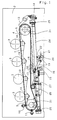
- the printing machine shown in Fig. 1 has a machine frame with two side walls 1 and 2, wherein the first side wall 1 can be seen in Fig. 3 and the second Sidewall 2 is shown in Figs. 1 and 2.
- An endless conveyor belt 4 runs around two rollers 5, 6, which are spaced apart are arranged perpendicular to the side walls 1, 2 of the printing press, such that the upper run of the conveyor belt 4 touches all four forme cylinders 3.
- the two rollers 5, 6 are not attached directly to the printing press, but rather stored in side parts 7, 8 of a tape carrier 9, one of the printing press detachable unit forms.
- the tape carrier 9, which is shown in more detail in FIGS. 4 and 5 is, the side parts 7, 8, the rollers 5, 6 and four counter-pressure rollers 10, the Press the conveyor belt 4 against the forme cylinder 3 while the printing press is operating.
- the Counter pressure rollers 10 can be adjusted individually, as can be seen in FIG. 5.
- the substrates or sheets to be printed are not shown by one Requests investors on the conveyor belt 4, the roller 5 or the roller 6 is driven, and by surface adhesion to the conveyor belt 4 or by the Forces in the printing nips between the forme cylinders 3 and the counter-pressure rollers 10 transported through, then to a not shown boom reach.
- the holding elements are a left and an upper one Adjustment stop 11, 12, which are located at the left end of the side part 7 and 8, respectively resilient stop 13 at the right end of the side part 7 or 8, which is a rotatable on the Side wall 1 or 2 is mounted lever, one end of which on the side part 7 or 8th can attack and the other end by an adjustable compression spring 14th is applied, as well as a roller lever at the bottom and approximately in the middle of the Side panels 7 and 8 respectively.
- the roller lever consists of an arm 15 which is pivotable at one end on the Side wall 1 or 2 is mounted and at the other end a roller 16 is mounted.
- a profile part 17, which is one of the rollers 16, is fastened to the side parts 7 and 8, respectively facing curve surface 18.
- each arm 15 In the operating position shown in FIGS. 1 to 3 of the tape carrier 9, each arm 15 is in a position in which the roller 16 against presses an elevated part of the curve surface 18 and in this way the corresponding one Side part 7 or 8 against the adjustment stops 11, 12 and the resilient stop 13 presses.
- a toggle linkage 19 is connected, which at one end at a Shaft 20 is fixed by the side wall 1 and 2 and that is in Fig. 1 to 3 in one stretched dead center position.
- a stable position can alternatively or can also be achieved by a schematically drawn tension spring 21 the toggle linkage 19 pulls against a stop 22 on the side wall 1 or 2.
- the Shaft 20 extends through the entire printing press, with one end of the Shaft 20 on the outside of the printing press with a handle or the like connected is.
- the side wall 1 has an elongated opening 23 (FIG. 3) which is larger than that Band carrier 9 is.
- a rectangular, in essentially flat drawer 24 (FIG. 1 or FIG. 6) which is attached to telescopic rails 25, which in turn are attached perpendicular to the side walls 1, 2 in the printing press.
- the drawer 24 is by means of the telescopic rails 25 like a drawer through the opening 23 can be pulled out of the printing press, as shown in broken lines in FIG. 6.
- a freely rotatable tension roller 26 is pivotally mounted extends perpendicular to the side walls 1, 2 across the width of the conveyor belt 4.
- the tensioning roller 26 is biased upwards by compression springs 27 (Fig. 1), i.e. in Direction to the conveyor belt 4.
- the machine operator rotates the shaft 20 counterclockwise, with the roller 16 to the right on the curved surface 18th rolls off.
- the tape carrier 9 lowers down.
- the location of the cam surface 18 and the strength of the spring force of the resilient stop 13 to compensate for tolerances serves, are chosen so that the tape carrier 9 initially when the circuit is actuated lowers only on the right side, the counter-pressure rollers 10 and the Conveyor belt 4 are separated from the forme cylinders 3.
- This intermediate position of the tape carrier 9 is in a depression or a step 30 in the curved surface 18 held.
- the embodiment of the belt carrier 9 shown in FIG. 4 is with a Integrated drive motor 28 which drives the roller 5.
- a gear 29, which is in the operating position and in the intermediate position of the tape carrier 9 with a gear on the printing press is engaged to drive any other machine parts. If the Belt carrier 9 does not have its own drive motor 28, but the roller 5 can also the gear 29 can be driven from the printing press, or it becomes another Gear provided on the roller 5, which in the intermediate position of the belt carrier 9 a drive motor is connected to the printing press.
- the band carrier 9 lowers on four prisms 31, which are mounted in the drawer 24.
- the spring force of the tension roller 26 is thereby Own weight of the tape carrier 9 overcome.
- the gear 29 is on the shaft 5 out of engagement with the printing press.
- For engaging and disengaging the Gear 29 is a relatively small change in position of the shaft 5, for example by 1 mm.
- the prisms 31, on which the axes of the shafts 5, 6 are placed, serve to fix the position of the tape carrier in the drawer 24, which is particularly important when reassembling of the tape carrier 9 is important.
- the drawer 24 can now together with the band carrier 9 lying thereon through the Pull opening 23 in side wall 1 out of the press.
- the tape carrier 9 is removed from the drawer 24, and the conveyor belt 4 can easily be done by hand deducted via the rollers 5 and 6 and replaced, since the tension roller 26 on the Drawer 24 remains.
- the tape carrier 9 is reinstalled in the reverse order.
Landscapes
- Delivering By Means Of Belts And Rollers (AREA)
- Handling Of Sheets (AREA)
- Supply, Installation And Extraction Of Printed Sheets Or Plates (AREA)
Description
- Fig. 1:
- einen Längsschnitt durch die Druckmaschine mit einem endlosen Bogentransportband, das sich auf einer herausnehmbaren Bandträgereinheit befindet;
- Fig. 2:
- eine Ansicht der in Fig. 1 verdeckten zweiten Seitenwand der Druckmaschine aus der gleichen Blickrichtung und zusammen mit einem zweiten Seitenteil der Bandträgereinheit,
- Fig. 3:
- eine Fig. 1 entsprechende Ansicht der ersten Seitenwand der Druckmaschine zusammen mit einem ersten Seitenteil der Bandträgereinheit;
- Fig. 4:
- eine Ansicht der Bandträgereinheit von oben, wobei das obere Trum des Transportbandes weggelassen ist;
- Fig. 5:
- einen Längsschnitt durch die Bandträgereinheit; und
- Fig. 6:
- eine Ansicht der Druckmaschine im Bereich der Lade von oben, wobei die Bandträgereinheit und das Transportband weggelassen sind.
- 1
- erste Seitenwand
- 2
- zweite Seitenwand
- 3
- Formzylinder
- 4
- Transportband
- 5, 6
- Walzen
- 7, 8
- Seitenteile
- 9
- Bandträger
- 10
- Gegendruckwalzen
- 11, 12
- Verstellanschläge
- 13
- federnder Anschlag
- 14
- einstellbare Druckfeder
- 15
- Arm
- 16
- Rolle
- 17
- Profilteil
- 18
- Kurvenfläche
- 19
- Kniehebelgestänge
- 20
- Welle
- 21
- Zugfeder
- 22
- Anschlag
- 23
- Öffnung
- 24
- Lade
- 25
- Teleskopschienen
- 26
- Spannrolle
- 27
- Druckfedern
- 28
- Antriebsmotor
- 29
- Zahnrad
- 30
- Stufe
- 31
- Prismen
Claims (7)
- Druckmaschine mit mehreren in Reihe angeordneten Druckwerken und einem endlosen Transportband für zu bedruckende Substrate, das um wenigstens zwei im Abstand angeordnete Walzen herum und an den Druckwerken vorbei verläuft,
dadurch gekennzeichnet,
daß die wenigstenszwei Walzen (5, 6) an einer zusammenhängenden Bandträgereinneit (9) gelagert sind, von der das Transportband (4) in einem ungespannten Zustand abziehbar ist, daß die Druckmaschine eine seitlich herausziehbare Lade (24) aufweist, die sich unterhalb der Bandträgereinheit (9) erstreckt, und daß an der Druckmaschine eine Haltevorrichtung (11, 12, 13, 15, 16) für die Bandträgereinheit (9) befestigt ist, die zwischen wenigstens zwei verschiedenen Zuständen umschaltbar ist, wobei in einem ersten Zustand die Bandträgereinheit von der Haltevorrichtung in einer Betriebsposition festgehalten wird und wobei in einem zweiten Zustand die Bandträgereinheit (9) lose auf der Lade (24) aufliegt. - Druckmaschine nach Anspruch 1,
dadurch gekennzeichnet,
daß eine Seitenwand (1) der Druckmaschine eine Öffnung (23) aufweist, durch die hindurch die Lade (24) zusammen mit der Bandträgereinheit (9) aus der Druckmaschine herausziehbar ist. - Druckmaschine nach Anspruch 1 oder 2,
dadurch gekennzeichnet,
daß an der Lade (24) eine federnd vorgespannte Spannrolle (26) zum Spannen des Transportbandes (4) angebracht ist. - Druckmaschine nach einem der vorhergehenden Ansprüche,
dadurch gekennzeichnet,
daß die Haltevorrichtung für die Bandträgereinheit (9) eine Anzahl von Anschlägen (11, 12, 13) und wenigstens zwei Schnellspanner (15, 16, 19 ,20, 21) umfaßt, wobei die Schnellspanner zwischen wenigstens zwei verschiedenen Positionen umstellbar sind, einer ersten Position, in der sie die Bandträgereinheit gegen die Anschläge (11, 12, 13) drücken, und einer zweiten Position, in der die Bandträgereinheit zu der Lade (24) hin freigegeben ist. - Druckmaschine nach Anspruch 4,
dadurch gekennzeichnet,
daß jeder Schnellspanner einen Arm (15) aufweist, der an einem Ende drehbar an der Druckmaschine gelagert ist und an dessen anderem Ende eine Rolle (16) drehbar gelagert ist, die auf einer dazugehörigen Kurvenfläche (18) an der Bandträgereinheit (9) abrollt, wenn der Arm (15) gedreht wird. - Druckmaschine nach einem der vorhergehenden Ansprüche,
dadurch gekennzeichnet,
daß die Haltevorrichtung zwischen dem ersten und dem zweiten Zustand wenigstens einen weiteren Schaltzustand aufweist, in dem sich die Bandträgereinheit (9) nicht in ihrer Betriebsposition befindet, aber zumindest teilweise an der Druckmaschine festgehalten wird. - Druckmaschine nach Anspruch 5 und 6,
dadurch gekennzeichnet,
daß der wenigstens eine weitere Schaltzustand der Haltevorrichtung mit Hilfe von Senken oder Stufen (30) in den Kurvenflächen (18) an der Bandträgereinheit (9) aufrechterhalten wird.
Applications Claiming Priority (2)
| Application Number | Priority Date | Filing Date | Title |
|---|---|---|---|
| DE19623563 | 1996-06-13 | ||
| DE19623563A DE19623563C1 (de) | 1996-06-13 | 1996-06-13 | Druckmaschine mit einem Bogentransportband |
Publications (3)
| Publication Number | Publication Date |
|---|---|
| EP0812684A2 EP0812684A2 (de) | 1997-12-17 |
| EP0812684A3 EP0812684A3 (de) | 1998-06-10 |
| EP0812684B1 true EP0812684B1 (de) | 1999-10-27 |
Family
ID=7796826
Family Applications (1)
| Application Number | Title | Priority Date | Filing Date |
|---|---|---|---|
| EP97107400A Expired - Lifetime EP0812684B1 (de) | 1996-06-13 | 1997-05-05 | Druckmaschine mit einem Bogentransportband |
Country Status (4)
| Country | Link |
|---|---|
| US (1) | US5915300A (de) |
| EP (1) | EP0812684B1 (de) |
| JP (1) | JPH1059576A (de) |
| DE (2) | DE19623563C1 (de) |
Families Citing this family (3)
| Publication number | Priority date | Publication date | Assignee | Title |
|---|---|---|---|---|
| US20040034686A1 (en) * | 2000-02-22 | 2004-02-19 | David Guthrie | System and method for delivering targeted data to a subscriber base via a computer network |
| DE10235800B4 (de) * | 2002-08-05 | 2004-10-21 | OCé PRINTING SYSTEMS GMBH | Anordnung zum Transport eines Aufzeichnungsträgers durch eine Umdruckanordnung einer elektrografischen Druck- oder Kopiereinrichtung |
| DE10236467B4 (de) * | 2002-08-08 | 2004-12-09 | OCé PRINTING SYSTEMS GMBH | Anordnung und Verfahren zur Einführung eines Aggregates in eine elektrografische Druck- oder Kopiereinrichtung |
Family Cites Families (13)
| Publication number | Priority date | Publication date | Assignee | Title |
|---|---|---|---|---|
| DE587513C (de) * | 1933-01-13 | 1933-11-04 | Georg Boettinger | Gummiwalzendruckmaschine zum ein- und mehrfarbigen Bedrucken verschieden dicker Bogen |
| US3785287A (en) * | 1968-06-17 | 1974-01-15 | H Dahlgren | Sheet interrupter |
| US3664261A (en) * | 1968-06-17 | 1972-05-23 | Harold P Dahlgren | Straight feed press |
| US4183296A (en) * | 1973-07-05 | 1980-01-15 | Heidelberger Druckmaschinen Aktiengesellschaft | Drive system for sheet-fed rotary printing presses with tandem-mounted printing units |
| US4081723A (en) * | 1975-05-02 | 1978-03-28 | Veb Polygraph Leipzog Kombinat Fur Polygraphische Maschinen Und Ausrustungen | Printing machine |
| NL7801102A (nl) * | 1978-01-31 | 1979-08-02 | Stork Brabant Bv | Inrichting voor het intermitterend drukken. |
| DE3312128C2 (de) * | 1983-04-02 | 1986-04-03 | M.A.N.- Roland Druckmaschinen AG, 6050 Offenbach | Vorrichtung an Druckmaschinen mit einer Einrichtung zum Lackieren von Druckbögen |
| AT381066B (de) * | 1983-10-06 | 1986-08-25 | Zimmer Johannes | Einrichtung zum bedrucken von warenbahnen mittels zylinderschablonen |
| US4625639A (en) * | 1986-09-12 | 1986-12-02 | Tsai Chien F | Continuous, multi-chromatic and multi-productive press |
| DE4004351C2 (de) * | 1990-02-13 | 1996-05-23 | Heidelberger Druckmasch Ag | Anlegetisch einer Bogendruckmaschine |
| JPH04148962A (ja) * | 1990-10-12 | 1992-05-21 | Canon Inc | 画像記録装置 |
| DE4243486C1 (de) * | 1992-12-22 | 1994-04-07 | Heidelberger Druckmasch Ag | Anlegetisch einer Bogendruckmaschine |
| IT1273544B (it) * | 1995-04-12 | 1997-07-08 | Bielloni Castello S P A | Macchina da stampa con dispositivo per la sostituzione rapida delle camicie dei cilindri dei gruppi inchiostratori |
-
1996
- 1996-06-13 DE DE19623563A patent/DE19623563C1/de not_active Expired - Fee Related
-
1997
- 1997-05-05 DE DE59700611T patent/DE59700611D1/de not_active Expired - Fee Related
- 1997-05-05 EP EP97107400A patent/EP0812684B1/de not_active Expired - Lifetime
- 1997-06-10 JP JP9151936A patent/JPH1059576A/ja active Pending
- 1997-06-13 US US08/874,258 patent/US5915300A/en not_active Expired - Lifetime
Also Published As
| Publication number | Publication date |
|---|---|
| US5915300A (en) | 1999-06-29 |
| EP0812684A3 (de) | 1998-06-10 |
| EP0812684A2 (de) | 1997-12-17 |
| JPH1059576A (ja) | 1998-03-03 |
| DE19623563C1 (de) | 1997-10-09 |
| DE59700611D1 (de) | 1999-12-02 |
Similar Documents
| Publication | Publication Date | Title |
|---|---|---|
| DE3220495C2 (de) | Fördervorrichtung für Zuschnitte | |
| EP1882661B1 (de) | Bogenbremsensystem zum Bremsen von Druckbogen | |
| DE2718299A1 (de) | Rotations-druckmaschine | |
| DE3923362C2 (de) | ||
| EP0450333A1 (de) | Bogenausleger für Druckmaschinen oder dergleichen | |
| DE2703424C2 (de) | Farbwerk für Offset-Druckmaschinen | |
| EP0054326B1 (de) | Transporteinrichtung zum Zuführen und Abführen eines Endlosformulares zu einer Schreibwalze | |
| EP0839649A2 (de) | Überführtrommel in einer Bogen verarbeitenden Druckmaschine | |
| DE3726780A1 (de) | Vorrichtung zur uebergabe von bogen | |
| DE3206295C2 (de) | Betätigungsmechanismus für eine Druckrakel und eine Farbverteilrakel einer Siebdruckmaschine | |
| DE10349668A1 (de) | Verfahren zum Transport von Bedruckstoffbögen und Bogentransportvorrichtung | |
| EP1110887B1 (de) | Leitvorrichtung zum Führen von Bogen und Verfahren zum Betreiben einer Leitvorrichtung | |
| DE19623563C1 (de) | Druckmaschine mit einem Bogentransportband | |
| DE69300644T2 (de) | Vorrichtung zum Zuführen eines Trägers durch eine Druckvorrichtung und Siebdruckmaschine. | |
| DE69708026T2 (de) | Mechanismus zum Öffnen und Schliessen von Greifern eines Bogentransportzylinders in einer Bogendruckmaschine | |
| EP1762529B1 (de) | Vorrichtung zur Bearbeitung bahnförmigen Materials | |
| EP0232553A1 (de) | Einrichtung zum Aufwickeln eines kontinuierlich anfallenden Schuppenstromes von biegsamen Flächengebilden zu einem Wickel | |
| DE102011118905B4 (de) | Bearbeitungsstation für eine Stanzmaschine | |
| DE4430159B4 (de) | Vorrichtung zum Umsetzen von Werkstückträgern | |
| DE102008019935B4 (de) | Übertragungstrommel zwischen Druckwerken einer Bogendruckmaschine | |
| DE2946597C2 (de) | Einspannvorrichtung für biegsame Druckplatten | |
| DE4213472C2 (de) | Vorrichtung zum Fördern flexibler Druckformen | |
| DE10315822A1 (de) | Drehbare Signaturenübergabevorrichtung | |
| DE19538322C2 (de) | Einrichtung zur axialen Verstellung von Leitelementen | |
| EP1155830B1 (de) | Drucktechnische Maschine mit Einrichtungen zur Beaufschlagung einer Walze mit einer Anpresskraft |
Legal Events
| Date | Code | Title | Description |
|---|---|---|---|
| PUAI | Public reference made under article 153(3) epc to a published international application that has entered the european phase |
Free format text: ORIGINAL CODE: 0009012 |
|
| 17P | Request for examination filed |
Effective date: 19970505 |
|
| AK | Designated contracting states |
Kind code of ref document: A2 Designated state(s): DE ES FR GB NL |
|
| PUAL | Search report despatched |
Free format text: ORIGINAL CODE: 0009013 |
|
| AK | Designated contracting states |
Kind code of ref document: A3 Designated state(s): DE ES FR GB NL |
|
| GRAG | Despatch of communication of intention to grant |
Free format text: ORIGINAL CODE: EPIDOS AGRA |
|
| GRAG | Despatch of communication of intention to grant |
Free format text: ORIGINAL CODE: EPIDOS AGRA |
|
| GRAH | Despatch of communication of intention to grant a patent |
Free format text: ORIGINAL CODE: EPIDOS IGRA |
|
| 17Q | First examination report despatched |
Effective date: 19990310 |
|
| GRAH | Despatch of communication of intention to grant a patent |
Free format text: ORIGINAL CODE: EPIDOS IGRA |
|
| GRAA | (expected) grant |
Free format text: ORIGINAL CODE: 0009210 |
|
| AK | Designated contracting states |
Kind code of ref document: B1 Designated state(s): DE ES FR GB NL |
|
| PG25 | Lapsed in a contracting state [announced via postgrant information from national office to epo] |
Ref country code: ES Free format text: THE PATENT HAS BEEN ANNULLED BY A DECISION OF A NATIONAL AUTHORITY Effective date: 19991027 |
|
| REF | Corresponds to: |
Ref document number: 59700611 Country of ref document: DE Date of ref document: 19991202 |
|
| GBT | Gb: translation of ep patent filed (gb section 77(6)(a)/1977) |
Effective date: 19991130 |
|
| ET | Fr: translation filed | ||
| PLBE | No opposition filed within time limit |
Free format text: ORIGINAL CODE: 0009261 |
|
| STAA | Information on the status of an ep patent application or granted ep patent |
Free format text: STATUS: NO OPPOSITION FILED WITHIN TIME LIMIT |
|
| 26N | No opposition filed | ||
| REG | Reference to a national code |
Ref country code: GB Ref legal event code: IF02 |
|
| PGFP | Annual fee paid to national office [announced via postgrant information from national office to epo] |
Ref country code: FR Payment date: 20020523 Year of fee payment: 6 |
|
| PGFP | Annual fee paid to national office [announced via postgrant information from national office to epo] |
Ref country code: NL Payment date: 20020524 Year of fee payment: 6 |
|
| PGFP | Annual fee paid to national office [announced via postgrant information from national office to epo] |
Ref country code: GB Payment date: 20030422 Year of fee payment: 7 |
|
| PG25 | Lapsed in a contracting state [announced via postgrant information from national office to epo] |
Ref country code: NL Free format text: LAPSE BECAUSE OF NON-PAYMENT OF DUE FEES Effective date: 20031201 |
|
| PG25 | Lapsed in a contracting state [announced via postgrant information from national office to epo] |
Ref country code: FR Free format text: LAPSE BECAUSE OF NON-PAYMENT OF DUE FEES Effective date: 20040130 |
|
| NLV4 | Nl: lapsed or anulled due to non-payment of the annual fee |
Effective date: 20031201 |
|
| REG | Reference to a national code |
Ref country code: FR Ref legal event code: ST |
|
| PG25 | Lapsed in a contracting state [announced via postgrant information from national office to epo] |
Ref country code: GB Free format text: LAPSE BECAUSE OF NON-PAYMENT OF DUE FEES Effective date: 20040505 |
|
| GBPC | Gb: european patent ceased through non-payment of renewal fee |
Effective date: 20040505 |
|
| PGFP | Annual fee paid to national office [announced via postgrant information from national office to epo] |
Ref country code: DE Payment date: 20060531 Year of fee payment: 10 |
|
| PG25 | Lapsed in a contracting state [announced via postgrant information from national office to epo] |
Ref country code: DE Free format text: LAPSE BECAUSE OF NON-PAYMENT OF DUE FEES Effective date: 20071201 |