EP0812230B1 - Bindung für das skispringen oder den tourenskilauf, insbesondere den skilauf im telemark-stil - Google Patents
Bindung für das skispringen oder den tourenskilauf, insbesondere den skilauf im telemark-stil Download PDFInfo
- Publication number
- EP0812230B1 EP0812230B1 EP19960901935 EP96901935A EP0812230B1 EP 0812230 B1 EP0812230 B1 EP 0812230B1 EP 19960901935 EP19960901935 EP 19960901935 EP 96901935 A EP96901935 A EP 96901935A EP 0812230 B1 EP0812230 B1 EP 0812230B1
- Authority
- EP
- European Patent Office
- Prior art keywords
- ski
- lever
- binding
- heel
- binding according
- Prior art date
- Legal status (The legal status is an assumption and is not a legal conclusion. Google has not performed a legal analysis and makes no representation as to the accuracy of the status listed.)
- Expired - Lifetime
Links
- 230000027455 binding Effects 0.000 title claims abstract description 59
- 238000009739 binding Methods 0.000 title claims abstract description 59
- 230000009191 jumping Effects 0.000 claims description 6
- 230000000694 effects Effects 0.000 claims description 4
- 238000003780 insertion Methods 0.000 claims description 4
- 230000037431 insertion Effects 0.000 claims description 4
- 238000010276 construction Methods 0.000 description 9
- 230000006835 compression Effects 0.000 description 6
- 238000007906 compression Methods 0.000 description 6
- 230000036316 preload Effects 0.000 description 4
- XEEYBQQBJWHFJM-UHFFFAOYSA-N Iron Chemical compound [Fe] XEEYBQQBJWHFJM-UHFFFAOYSA-N 0.000 description 2
- 230000002411 adverse Effects 0.000 description 1
- 230000000295 complement effect Effects 0.000 description 1
- 229910052742 iron Inorganic materials 0.000 description 1
- 239000000463 material Substances 0.000 description 1
- 229920001296 polysiloxane Polymers 0.000 description 1
- 230000001960 triggered effect Effects 0.000 description 1
- 238000011144 upstream manufacturing Methods 0.000 description 1
Images



Classifications
-
- A—HUMAN NECESSITIES
- A63—SPORTS; GAMES; AMUSEMENTS
- A63C—SKATES; SKIS; ROLLER SKATES; DESIGN OR LAYOUT OF COURTS, RINKS OR THE LIKE
- A63C9/00—Ski bindings
- A63C9/20—Non-self-releasing bindings with special sole edge holders instead of toe-straps
-
- A—HUMAN NECESSITIES
- A63—SPORTS; GAMES; AMUSEMENTS
- A63C—SKATES; SKIS; ROLLER SKATES; DESIGN OR LAYOUT OF COURTS, RINKS OR THE LIKE
- A63C9/00—Ski bindings
- A63C9/02—Non-self-releasing bindings with swivel sole-plate or swivel parts, i.e. Ellefsen-type
-
- A—HUMAN NECESSITIES
- A63—SPORTS; GAMES; AMUSEMENTS
- A63C—SKATES; SKIS; ROLLER SKATES; DESIGN OR LAYOUT OF COURTS, RINKS OR THE LIKE
- A63C9/00—Ski bindings
- A63C9/06—Non-self-releasing heel-engaging cable bindings fastened to the front end of the ski
-
- A—HUMAN NECESSITIES
- A63—SPORTS; GAMES; AMUSEMENTS
- A63C—SKATES; SKIS; ROLLER SKATES; DESIGN OR LAYOUT OF COURTS, RINKS OR THE LIKE
- A63C2201/00—Use of skates, skis, roller-skates, snowboards and courts
- A63C2201/04—Ski jumping
-
- A—HUMAN NECESSITIES
- A63—SPORTS; GAMES; AMUSEMENTS
- A63C—SKATES; SKIS; ROLLER SKATES; DESIGN OR LAYOUT OF COURTS, RINKS OR THE LIKE
- A63C2201/00—Use of skates, skis, roller-skates, snowboards and courts
- A63C2201/06—Telemark
Definitions
- the invention relates to a binding for ski jumping or touring skiing, especially telemark skiing, according to the preamble of claim 1.
- DE-4 338 590 discloses a binding for touring skiing known, in which the ski boot over the front sole end in is held in such a way that the ski boot from the Ski or from a support element which is on the ski attached, can be raised.
- the ski boot is through a telemark binding attached to a plate in Location held.
- Such a telemark binding is also known from EP-495 192 known.
- the ski boot is typically on his front sole end held in position by a tension rope which runs around the ski boot heel.
- the tension rope is directly at both ends with a tensioning mechanism coupled, with which the ski boot can be fixed to a toe iron is such that when cross-country skiing or hiking the Boot heel or the heel of the cross-country skier from the Ski cover area can be lifted off.
- the tension rope is also still a facility for changing its effective length assigned. Furthermore, part of the tension rope is through a tension spring replaced.
- the one around the boot heel part of the tensioning rope that can be passed around is attached to the Boot sole supportable tension lever pivotally mounted, the pivot axis extending parallel to the tensioning cable.
- a heel holding device is known from EP-548 806, which is movable on all sides, like a band trained tension member, with one end on Ski is attached and with its other end by means of a Clamp on a pin on the heel of the boot can be fixed. By means of this clamp, the tension member can be released at will and when occurring at a substantially toward the Boot sole pulling force from the tenon on the boot heel removable.
- On the tension member there are two at a distance from each other Parts of a connector are fastened adjustable. The both parts form one like a push button trained connector. In the closed state of the Connector remains a loop of the tension member, the after loosening the connector under the action of a increased tensile force leads to an extension of the tension member, whereby the heel of the boot is raised further from the ski can.
- Bonds of this type and the type mentioned at the beginning can for cross-country skiing, touring skiing, skiing corresponding to the Telemark style and which has become modern again especially used for jump skis.
- the trigger part opposite the base part has at least three freely rotatable stored guide rollers with circumferential grooves in the Engaging guide flanges on the bottom of the Trigger part are bent downwards and inwards and thus with their inwardly curved edges in the circumferential grooves intervention. Are located between the guide flanges Cutouts so that the trigger part after a certain Twist relative to the base part from the guide rollers can get free.
- the trigger part is a trigger cam firmly connected, the one central recess and two has symmetrically arranged control curves.
- One against the Effect of springs of a trigger mechanism slidable Control roller engages in the recess in the position of use and rolls into one of the Control curves.
- the present invention has for its object a To create bond of the type mentioned at the outset due to an extremely simple construction with a minimum of Characterized individual parts and yet an extremely reliable Represents security binding.
- the invention includes Security tie just one by one yourself pivotable perpendicular to the ski deck surface axis mounted lever on which the cable or band-like tensioning element, which is led around the heel of the boot, is connected, and the in case of fall-related rotation of the Ski boots from the ski-parallel position in a predetermined Angle of the swivel axis is released with the result that the Boots are released from the binding altogether. It is said lever to which the cable or band-like tensioning element can be connected below a cover plate held pivotable.
- the advantageous measure should also be mentioned Arrangement of at least one resilient element as part of the cable or band-like tensioning element.
- This resilient Element becomes the secure hold of the Ensures tensioning element around the boot heel, and with every raised position of the boot heel.
- this measure increases resistance in the Raise the heel of the boot with increasing lifting accordingly.
- the resilient element provides a kind of limitation against too much lifting of the heel of the boot represents.
- Corresponding Claim 6 is the opening angle of the part-circular Recess smaller than the angle over which the longer one Circular arc section of the axle plate extends. This ensures that the lever in the transverse position or in position is held transversely to the longitudinal direction of the ski on the axle plate. At Swiveling the lever out of this position by an angle, which is only slightly larger than the overlap angle between one end of the longer circular arc section of the Axis plate and the circumference of the corresponding circle Recess, the lever slides back from the axle plate off with the appropriate release of the boot from the then accordingly loosened clamping element.
- the mentioned overlap angle is approximately 2 with the lever in the exact transverse position up to 5 °.
- the present invention encompasses also a binding on the ski or heel support a tape or cord-like means of limiting lifting the heel of the boot from the ski or heel support element, which at the rear section of the cable or band-like tensioning element can be connected.
- this heel movement limiting means is elastically biased, especially against the action of an elastic spring element extendable.
- the elastic spring element arranged on a within the heel support element Sled are located by means of an outside accessible adjustment screw can be moved in the longitudinal direction of the ski is.
- the heel support element already mentioned several times can after kind of a base, in particular in the form of a truncated cone Be formed base, the one facing the paragraph Top extends obliquely downwards towards the front.
- This embodiment of the heel support element is particularly advantageous for jump skis.
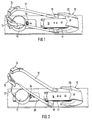
- the security binding shown in Figs. 1 and 2 for a jump ski is supported by a toe 10 the front sole end of a not shown Ski boots up, front and to the side, as well as a Boot heel support element 11 and a band-like tensioning element 12 marked, which the boot with its front Sole end in the jaw 10 holds that it is about the boot heel is led around, namely under elastic pretension.
- the elastic preload is by itself known, effective clamping lever applied in the sales area, that is indicated in FIGS. 1 and 2 with the reference number 13 is. This is a known measure, the construction of which need not be explained in more detail.
- the band-like tensioning element or tensioning band preferably comprises 12 still at least one elastic, in particular spring-elastic Use for the purpose of elastic preload of the strap in the closed state. Against the effect this spring-elastic insert, the clamping lever 13 in Be brought into the closed position.
- the strap 12 includes one Coarse-length adjustment device 14, as is the case with the buckles is known from ski boots. Accordingly there is also no need for a more detailed description of this facility.
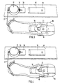
- Seen in the longitudinal direction of the ski in front of the toe 10 is on the ski deck surface has a base plate 15 mounted (see FIG. 3 and 4). Above this is a cover plate 16, wherein a gap between the cover plate 16 and the base plate 15 17 is limited by the transverse to the longitudinal direction Lever 18 extends through, the free ends laterally over protrude the base plate 15 and cover plate 16 and on which the two front ends of the around the boot heel Tension band are connectable.
- the lever 16 is in the Bale area between base plate 15 and cover plate 16 around one perpendicular to the ski top surface or not shown Boot sole extending axis 19 (see Fig.
- lever 18th and pivot axis 19 are such that the lever 18 after exceeding a predetermined angle out of the exact transverse position comes out of engagement with the pivot axis 19, such as this in comparison to FIGS. 1 and 3 shown in FIGS. 2 and 4 is.
- the lever 18 mentioned disengaged arrives with the pivot axis 19, this can be due the force acting on the strap 12 within the Move gap 17 backwards under the corresponding Loosening the strap 12 and releasing the held by this Ski boots.
- the release position of the strap 12 is shown in Fig. 2.
- the two front ends of the Tension band 12 on the two free and laterally over the Base plate and cover plate projecting ends of the pivotable held lever connected, the free Ends of the lever 18 are preferably formed so that a Connection of the strap to different in the longitudinal direction of the ski Positions is possible.
- several Tension strap receiving slots at the free ends of the lever 18 be provided, in each case in predetermined in the longitudinal direction of the ski Distances from each other.
- the toe 10 mentioned above is in top or bottom Bottom view approximately U-shaped. It serves as a support of the front end of the boot to the side and to the side at the front.
- the shoe 10 is a holding element that extends over the front sole end in the form of a retaining tab that extends to the rear arranged to support the front sole end serves upwards.
- the already mentioned pivot axis 19 for the lever 18 is for one attached to the underside of the cover plate 16, approximately trapezoidal axis plate 21, the Baseline segments of a circle lying on the same diameter 22, 23 define, and secondly by a corresponding part-circular recess 24 on lever 18 formed, wherein the axle plate 21 is positioned so that its longer circular arc section 23 faces forward.
- the Partially circular recess 24 on the lever 18 is also behind open at the front, so that through this opening 25 through Axle plate 21 can be inserted into said recess 24 or can be moved out of this.
- the aforementioned features of Pivot axis 19 can best be seen in FIG. 9.
- the Pivot axis 19 is therefore on the one hand by the binding side attached axle plate 21 and the other by a corresponding part-circular recess 24 on lever 18 Are defined.
- the opening angle of the part-circular recess 24 is, as can be seen particularly well in FIG. 3, smaller than the angle over which the longer arc section extends 23 of the axle plate 21 extends.
- the overlap between the longer circular arc section 23 of the axle plate 21 and the Partial circumference of the corresponding recess 24 is on both sides of the front access opening 25 with more exact Transverse position of the lever 18 in each case about 2 to 5 °.
- Lever 18 by an elastic element in the exact transverse position preload.
- This embodiment is particularly preferred if the binding is a touring ski or telemark binding Should be used.
- Elastic preferably act Upholstery on the free ends of the lever 18, on the opposite side of the tensioning strap 12.
- an elastic Element e.g. B. a plate corresponding to the gap thickness made of elastic plastic material, in particular silicone or Like.
- the hardness of the elastic element mentioned changeable or variably adjustable. At least should be provided be that the elastic element by more or less hard elements is interchangeable. Basically would be a coil spring element is also conceivable, which in the area of Front jaw 10 arranged and the end of a cable is connected to the free ends of the lever 18.
- the above-mentioned heel support member 11 is frustoconical Base formed, the one facing the paragraph Top 28 is sloping downward toward the front extends, namely by an angle of about 3 to 10 °, in particular about 5 ° to the horizontal.
- the so trained Heel support element is on the mounting plate 29 on the Ski cover surface 30 attached, by means of not shown Mounting screws.
- Inside the heel support 11 is one end of a cord-like means 31 to limit the lifting of the boot heel from the ski or connected from the top 28 of the heel support element 11, while the other end at the rear section of the strap 12 can be connected, is knotted here. Means this knot can be a rough adjustment of the effective Length of the paragraph movement limiting cord 31 take place.
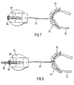
- the heel movement restricting cord 31 elastically biased, by means of a tension spring arranged within a threaded sleeve 32 33 (see Fig. 8).
- the threaded sleeve 32 provides one kind of slide, which is supported by means of a binding and knurled nut that is accessible or operable from the outside for the purpose of fine-tuning the effective Length of the heel movement limiting cord 31 in the longitudinal direction of the ski can be pushed back and forth.
- At the ski rear end of the truncated cone-shaped heel support element 11 is an opening 35 for passage of the heel movement restricting cord 31 formed in the one deflection plate 36 for the deflection of the heel movement limiting cord 31 is rotatably mounted upwards.
- the two front jaws 10 of the binding laterally in Direction of arrows 37 deflectable, in the embodiment 10 against the action of a compression spring 38, and in the embodiment according to FIG. 11 against the effect a tension spring 39.
- the deflection of the jaws 10 takes place each around a perpendicular to the ski deck area Axis 41. Towards each other or inwards, the Deflection movement of the jaws 10 by binding or ski-fixed Stops 42 limited.
- the compression spring 38 acts in the embodiment according to FIG. 10 between two each forward over the axes 41 extending extensions 40 of the jaws 10.
- the compression spring 38 thus urges the jaws 10 against the abovementioned stops 42.
- the compression spring allows the ski spring to act as a torsion force 38 a lateral deflection of the respectively loaded jaw 10 with the result that the shoe is released without constraint.
- connection points for the connecting elements 43 are each relative to the pivot axis 41 of the associated jaw 10 laterally lie inward. These connection points are shown in Fig. 11 marked with the reference number 44.
- the spring elements 38, 39 can by coil springs, leaf springs or elastic resilient plastic body formed his.
Landscapes
- Footwear And Its Accessory, Manufacturing Method And Apparatuses (AREA)
Abstract
Description
- Fig. 1
- eine Sicherheitsbindung für das Skispringen gemäß Erfindung in perspektivischer Seiten-Schrägansicht;
- Fig. 2
- die Sicherheitsbindung gemäß Fig. 1 in ausgelöstem Zustand;
- Fig. 3
- die Sicherheitsbindung gemäß Fig. 1 bzw. Fig. 2 im teil-zerlegten Zustand, wobei der vordere Haltebacken samt Auslösemechanismus um 180° gedreht dargestellt ist;
- Fig. 4
- die Darstellung entsprechend Fig. 3 im Auslösezustand;
- Fig. 5
- die Darstellung entsprechend Fig. 4 in noch weiter zerlegtem Zustand;
- Fig. 6
- das von der Skideckfläche demontierte Absatzstützelement von der Unterseite;
- Fig. 7
- das Absatzstützelement entsprechend Fig. 6 von der Unterseite nach Entfernung einer Montage-Grundplatte;
- Fig. 8
- das Absatzstützelement entsprechend Fig. 7 unter Darstellung eines elastischen Vorspannelements für ein schnurartiges Absatzbewegungs-Begrenzungsmittel;
- Fig. 9
- das bei der Bindung entsprechend den vorgenannten Figuren verwendete Absatzstützelement in perspektivischer Ansicht von hinten oben unter Darstellung des schnurartigen Absatzbewegungs-Begrenzungsmittels samt kabel- bzw. bandartigem Spannelement und Teil des Auslösemechanismus für dieses; und
- Fig. 10 und 11
- eine schematische Draufsicht auf den vorderen Teil von zwei unterschiedlichen Ausführungsformen einer Bindung mit seitlich auslenkbaren Sohlenbacken.
- 10
- (Vorder-) Backen
- 11
- Absatzstützelement
- 12
- Spannelement (Spannband)
- 13
- Spannhebel
- 14
- Groblängen-Einstelleinrichtung für das Spannband 12
- 15
- Grundplatte
- 16
- Abdeckplatte
- 17
- Spalt
- 18
- Schwenkhebel
- 19
- Schwenkachse
- 20
- Haltelasche
- 21
- Achsplatte
- 22
- Kreisbogenabschnitt (kurz)
- 23
- Kreisbogenabschnitt (lang)
- 24
- Ausnehmung
- 25
- (stirnseitige) Öffnung
- 26
- kreisbogenförmiger Hebelabschnitt
- 27
- Einführtrichter
- 28
- Oberseite
- 29
- Montageplatte
- 30
- Skideckfläche
- 31
- Absatzbewegungs-Begrenzungsmittel
- 32
- Gewindehülse
- 33
- Schraubenzugfeder
- 34
- Rändelmutter
- 35
- Öffnung
- 36
- Umlenkscheibe
- 37
- Pfeil
- 38
- Druckfeder
- 39
- Zugfeder
- 40
- Fortsätze
- 41
- Achse
- 42
- Anschlag
- 43
- Verbindungselement
- 44
- Anschlußpunkt
Claims (22)
- Bindung für das Skispringen oder den Tourenskilauf, insbesondere den Skilauf im Telemark-Stil, bei der der Stiefel an seinem vorderen Sohlenende derart gehalten ist, daß der Stiefelabsatz vom Ski bzw. von einem skifesten Absatzstützelement (11) anhebbar ist, wobei der Halt des Stiefels an seinem vorderen Sohlenende durch ein entweder um den Stiefelabsatz herumgeführtes oder durch ein im Ballenbereich an der Vordersohle, insbesondere an der Unterseite derselben anschließbares Spannkabel oder Spannband (12) gewährleistet ist,
dadurch gekennzeichnet, daß
das kabel- oder bandartige Spannelement (12) mit seinen beiden im montierten Zustand vorderen Enden unmittelbar an einem sich quer zur Skilängsrichtung erstreckenden, unterhalb der Stiefelsohle im Ballenbereich derselben am Skikörper bzw. an einem vorderen Teil der Bindung um eine sich senkrecht zur Skideckfläche (30) bzw. Stiefelsohle erstreckende Achse (19) verschwenkbar gehaltenen Hebel (18) angeschlossen ist, wobei dieser nach Überschreiten eines vorbestimmten Winkels aus der exakten Querlage heraus außer Eingriff mit der Schwenkachse (19) kommt, wobei der Hebel (18) an den das kabel- oder bandartige Spannelement (12) anschließbar ist, unterhalb einer Abdeckplatte (16) verschwenkbar gehalten ist. - Bindung nach Anspruch 1,
dadurch gekennzeichnet, daß die beiden im montierten Zustand vorderen Enden des kabel- oder bandartigen Spannelements (12) an den beiden freien Enden des verschwenkbar gehaltenen Hebels (18) anschließbar sind, insbesondere an in Skilängsrichtung unterschiedlichen Positionen. - Bindung nach Anspruch 1 oder 2,
dadurch gekennzeichnet, daß der vordere Teil der Bindung einen U-förmigen Backen (10) zur Abstützung des vorderen Sohlenendes zur Seite, nach oben und nach vorne hin umfaßt, wobei die Abstützung nach oben hin vorzugsweise durch ein das vordere Sohlenende übergreifendes Halteelement (20) erfolgt, welches am Quersteg des U-förmigen Backens (10) angeordnet ist. - Bindung nach Anspruch 1,
dadurch gekennzeichnet, daß der Hebel (18) in einem Spalt (17) zwischen der Abdeckplatte (16) und der Skideckfläche (30) oder einer auf dieser befestigten Grundplatte (15) verschwenkbar gehalten ist. - Bindung nach einem der Ansprüche 1 bis 4,
dadurch gekennzeichnet, daß die Schwenkachse (19) für den Hebel (18) zum einen durch eine bindungs- oder hebelseitig angeordnete, etwa trapezförmig ausgebildete Achsplatte (21), deren Grundlinien auf demselben Durchmesser liegende Kreisbogenabschnitte (22, 23) definieren, und zum anderen durch eine korrespondierende teilkreisförmige Ausnehmung (24) am Hebel (18) oder alternativ bindungsseitig gebildet ist, wobei die Achsplatte (21) so positioniert ist, daß ihr längerer Kreisbogenabschnitt (23) nach vorne zeigt, und wobei die teilkreisförmige Ausnehmung (24) ebenfalls nach vorne hin offen ist, so daß durch diese Öffnung (25) hindurch die Achsplatte (21) in die erwähnte Ausnehmung (24) einführbar bzw. aus dieser herausbewegbar ist. - Bindung nach Anspruch 5,
dadurch gekennzeichnet, daß die Achsplatte (21) an der Unterseite der Abdeckplatte (16) oder an der Oberseite der Grundplatte (15) befestigt ist und daß der Öffnungswinkel der teilkreisförmigen Ausnehmung (24) kleiner ist als der Winkel, über den sich der längere Kreisbogenabschnitt (23) der Achsplatte (21) erstreckt. - Bindung nach Anspruch 6,
dadurch gekennzeichnet, daß die Überlappung zwischen dem längeren Kreisbogenabschnitt (23) der Achsplatte (21) und dem Teilkreisumfang der korrespondierenden Ausnehmung (24) am Hebel (18) zu beiden Seiten ihrer Zugangsöffnung (25) bei exakter Querlage des Hebels (18) jeweils etwa 2 bis 5° beträgt. - Bindung nach einem der Ansprüche 1 bis 7,
dadurch gekennzeichnet, daß der Hebel (18) durch ein elastisches Element in exakte Querlage vorgespannt ist. - Bindung nach Anspruch 8,
dadurch gekennzeichnet, daß die Härte des elastischen Elements veränderbar bzw. variabel einstellbar ist. - Bindung nach einem der Ansprüche 1 bis 9,
dadurch gekennzeichnet, daß die teilkreisförmige Ausnehmung (24) im Hebel (18) innerhalb eines kreisbogen-, insbesondere halbkreisbogenförmigen Mittelabschnitts (26) desselben ausgebildet ist, und daß der stirnseitigen Öffnung (25) der im Hebel (18) ausgebildeten Teilkreis-Ausnehmung (24) ein Einführtrichter (27) vorgeordnet ist. - Bindung nach einem der Ansprüche 1 bis 10,
dadurch gekennzeichnet, daß sie ein am Ski oder Absatzstützelement (11) angeordnetes band- oder schnurartiges Mittel (31) zur Begrenzung des Anhebens des Stiefelabsatzes vom Ski bzw. Absatzstützelement (11) umfaßt, welches am rückwärtigen Abschnitt des kabel- oder bandartigen Spannelements (12) anschließbar ist. - Bindung nach Anspruch 11,
dadurch gekennzeichnet, daß die wirksame Länge des Absatzbewegungs-Begrenzungsmittels (31) einstellbar ist. - Bindung nach Anspruch 11,
dadurch gekennzeichnet, daß das Absatzbewegungs-Begrenzungsmittel (31) elastisch vorgespannt ist, insbesondere gegen die Wirkung eines elastischen Elements (Federelement 33) verlängerbar ist. - Bindung nach Anspruch 13,
dadurch gekennzeichnet, daß das elastische Element (33) auf einem innerhalb des Absatzstützelements (11) angeordneten Schlitten (Gewindehülse 32) montiert ist, der zum Zwecke einer Feineinstellung der wirksamen Länge des Absatzbewegungs-Begrenzungsmittels (31) mittels einer von außen her zugänglichen und ski- oder bindungsseitig abgestützten Einstellschraube oder -mutter (34) in Skilängsrichtung verschiebbar ist. - Bindung nach einem der Ansprüche 1 - 14,
dadurch gekennzeichnet, daß das Absatzstützelement (11) nach Art eines Sockels, insbesondere in Form eines kegelstumpfförmigen Sockels ausgebildet ist, dessen dem Absatz zugekehrte Oberseite (28) sich in Richtung nach vorne schräg nach unten erstreckt. - Bindung nach Anspruch 15,
dadurch gekennzeichnet, daß am hinteren Ende des Sockels (11) eine Öffnung (35) für den Durchtritt des Absatzbewegungs-Begrenzungsmittels (31) ausgebildet ist, in der vorzugsweise eine Umlenkscheibe (36) für die Umlenkung des Absatzbewegungs-Begrenzungsmittels (31) nach oben drehbar gelagert ist. - Bindung nach einem der Ansprüche 11 bis 16,
dadurch gekennzeichnet, daß das Absatzbewegungs-Begrenzungsmittel (31) mit der Möglichkeit einer Groblängeneinstellung am hinteren Abschnitt des kabel- oder bandartigen Spannelements (12) anschließbar ist. - Bindung nach einem der Ansprüche 1 - 17,
dadurch gekennzeichnet, daß das kabel- oder bandartige Spannelement (12) eine eine Längenveränderung erlaubende Spanneinrichtung, insbesondere einen Spannhebelmechanismus (13) umfaßt. - Bindung nach einem der Ansprüche 1 - 18,
dadurch gekennzeichnet, daß das kabel- oder bandartige Spannelement (12) wenigstens einen federelastischen Abschnitt umfaßt. - Bindung nach einem der Ansprüche 1 bis 19,
dadurch gekennzeichnet, daß der U-förmige Backen (10) zur Abstützung des vorderen Sohlenendes zwei Einzelbacken umfaßt, die jeweils um eine sich senkrecht zur Skideckfläche erstreckende Achse (41) verschwenkbar und gegen die Wirkung eines elastischen Elements (38; 39) seitlich auslenkbar sind. - Bindung nach Anspruch 20,
dadurch gekennzeichnet, daß die Härte des elastischen Elements (38; 39) einstellbar ist. - Bindung nach Anspruch 20 oder 21,
dadurch gekennzeichnet, daß die Einzelbacken durch das zugeordnete elastische Element (38; 39) gegen ski- oder bindungsfeste Anschläge (42) gedrängt sind, die die Auslenkung der Backen nach innen bzw. aufeinander zu begrenzen.
Applications Claiming Priority (3)
| Application Number | Priority Date | Filing Date | Title |
|---|---|---|---|
| DE19506384 | 1995-02-23 | ||
| DE1995106384 DE19506384C1 (de) | 1995-02-23 | 1995-02-23 | Bindung für das Skispringen oder den Tourenskilauf, insbesondre den Skilauf im Telemark-Stil |
| PCT/IB1996/000139 WO1996025987A1 (de) | 1995-02-23 | 1996-02-22 | Bindung für das skispringen oder den tourenskilauf, insbesondere den skilauf im telemark-stil |
Publications (2)
| Publication Number | Publication Date |
|---|---|
| EP0812230A1 EP0812230A1 (de) | 1997-12-17 |
| EP0812230B1 true EP0812230B1 (de) | 2000-05-17 |
Family
ID=7754878
Family Applications (1)
| Application Number | Title | Priority Date | Filing Date |
|---|---|---|---|
| EP19960901935 Expired - Lifetime EP0812230B1 (de) | 1995-02-23 | 1996-02-22 | Bindung für das skispringen oder den tourenskilauf, insbesondere den skilauf im telemark-stil |
Country Status (3)
| Country | Link |
|---|---|
| EP (1) | EP0812230B1 (de) |
| DE (2) | DE19506384C1 (de) |
| WO (1) | WO1996025987A1 (de) |
Families Citing this family (2)
| Publication number | Priority date | Publication date | Assignee | Title |
|---|---|---|---|---|
| EP2430933B1 (de) | 2010-09-21 | 2019-01-23 | Tom Rass | Skisprungstiefel und Bindungssystem umfassend einen Sprungstiefel und eine Skibindung |
| DE202018000659U1 (de) | 2018-02-09 | 2018-03-01 | Volkmar Rass | Skibindung |
Family Cites Families (4)
| Publication number | Priority date | Publication date | Assignee | Title |
|---|---|---|---|---|
| DE1888140U (de) * | 1964-02-20 | Wiener Metallwaren- und Schnallenfabrik Schar-Smolka, Schwechat (Österreich) | Vorrichtung zur Längenverstellung | |
| US5066036A (en) * | 1990-03-19 | 1991-11-19 | Broughton Timothy C | Ski binding |
| DE4143411C2 (de) * | 1991-12-20 | 1995-06-29 | Silvretta Sherpas Sportartikel | Sicherheitsbindung |
| DE4338590A1 (de) * | 1993-05-27 | 1994-12-01 | Rottefella As | Skibindungsanordnung zum Festlegen eines Skischuhs auf einem Ski, insbesondere Touren- oder Langlauf-Ski |
-
1995
- 1995-02-23 DE DE1995106384 patent/DE19506384C1/de not_active Expired - Fee Related
-
1996
- 1996-02-22 EP EP19960901935 patent/EP0812230B1/de not_active Expired - Lifetime
- 1996-02-22 DE DE59605254T patent/DE59605254D1/de not_active Expired - Fee Related
- 1996-02-22 WO PCT/IB1996/000139 patent/WO1996025987A1/de not_active Ceased
Also Published As
| Publication number | Publication date |
|---|---|
| WO1996025987A1 (de) | 1996-08-29 |
| EP0812230A1 (de) | 1997-12-17 |
| DE59605254D1 (de) | 2000-06-21 |
| DE19506384C1 (de) | 1996-08-29 |
Similar Documents
| Publication | Publication Date | Title |
|---|---|---|
| DE2502956C2 (de) | Sohlenniederhalter für eine Ski-Sicherheitsbindung | |
| DE2023169A1 (de) | Sicherheits-Skibindungs-System | |
| DE202009019128U1 (de) | Zeheneinheit für Tourenskibindung | |
| EP3928842B1 (de) | Vordereinheit für eine tourenbindung | |
| DE2510385A1 (de) | Ausloesende skibindung mit einer schwenkbar um ein skifestes lager gelagerten schuhtrittplatte | |
| EP0548806A2 (de) | Skibindung | |
| DE102009046396A1 (de) | Vorderbacken für eine Tourenskibindung und Skischuh für eine Tourenskibindung | |
| EP1385585A1 (de) | Skibindung | |
| EP3345659A1 (de) | Fersenautomat für eine skibindung | |
| DE2209055A1 (de) | Vorderbacken fuer sicherheits-skibindungen | |
| DE4142390A1 (de) | Sicherheitsbindung fuer sprungski | |
| DE1188487B (de) | Skibindung | |
| DE3151162A1 (de) | Ausloeseskibindung | |
| DE1578875A1 (de) | Hinterer Skibindungsteil | |
| DE4124046A1 (de) | Langlaufskibindung | |
| DE19506384C1 (de) | Bindung für das Skispringen oder den Tourenskilauf, insbesondre den Skilauf im Telemark-Stil | |
| DE4424737C1 (de) | Snowboardbindung | |
| EP1795236B1 (de) | Skibindung | |
| DE2217273A1 (de) | Auslösende Skibindung für den Abfahrtslauf | |
| DE2608073A1 (de) | Fersenniederhalter fuer sicherheits- skibindungen | |
| DE2907359A1 (de) | Langlauf-sicherheitsskibindung | |
| CH616344A5 (de) | ||
| DE1578718C3 (de) | Auslösender Fersenhalter einer Skibindung | |
| EP0495192A1 (de) | Ski-Langlauf-Bindung | |
| CH617594A5 (de) |
Legal Events
| Date | Code | Title | Description |
|---|---|---|---|
| PUAI | Public reference made under article 153(3) epc to a published international application that has entered the european phase |
Free format text: ORIGINAL CODE: 0009012 |
|
| 17P | Request for examination filed |
Effective date: 19970711 |
|
| AK | Designated contracting states |
Kind code of ref document: A1 Designated state(s): DE FR IT |
|
| 17Q | First examination report despatched |
Effective date: 19990426 |
|
| GRAG | Despatch of communication of intention to grant |
Free format text: ORIGINAL CODE: EPIDOS AGRA |
|
| GRAG | Despatch of communication of intention to grant |
Free format text: ORIGINAL CODE: EPIDOS AGRA |
|
| GRAH | Despatch of communication of intention to grant a patent |
Free format text: ORIGINAL CODE: EPIDOS IGRA |
|
| GRAH | Despatch of communication of intention to grant a patent |
Free format text: ORIGINAL CODE: EPIDOS IGRA |
|
| GRAA | (expected) grant |
Free format text: ORIGINAL CODE: 0009210 |
|
| AK | Designated contracting states |
Kind code of ref document: B1 Designated state(s): DE FR IT |
|
| PG25 | Lapsed in a contracting state [announced via postgrant information from national office to epo] |
Ref country code: IT Free format text: LAPSE BECAUSE OF FAILURE TO SUBMIT A TRANSLATION OF THE DESCRIPTION OR TO PAY THE FEE WITHIN THE PRE;WARNING: LAPSES OF ITALIAN PATENTS WITH EFFECTIVE DATE BEFORE 2007 MAY HAVE OCCURRED AT ANY TIME BEFORE 2007. THE CORRECT EFFECTIVE DATE MAY BE DIFFERENT FROM THE ONE RECORDED.SCRIBED TIME-LIMIT Effective date: 20000517 |
|
| REF | Corresponds to: |
Ref document number: 59605254 Country of ref document: DE Date of ref document: 20000621 |
|
| ET | Fr: translation filed | ||
| PLBE | No opposition filed within time limit |
Free format text: ORIGINAL CODE: 0009261 |
|
| STAA | Information on the status of an ep patent application or granted ep patent |
Free format text: STATUS: NO OPPOSITION FILED WITHIN TIME LIMIT |
|
| 26N | No opposition filed | ||
| PG25 | Lapsed in a contracting state [announced via postgrant information from national office to epo] |
Ref country code: FR Free format text: LAPSE BECAUSE OF NON-PAYMENT OF DUE FEES Effective date: 20011031 |
|
| REG | Reference to a national code |
Ref country code: FR Ref legal event code: ST |
|
| PGFP | Annual fee paid to national office [announced via postgrant information from national office to epo] |
Ref country code: DE Payment date: 20011228 Year of fee payment: 7 |
|
| PG25 | Lapsed in a contracting state [announced via postgrant information from national office to epo] |
Ref country code: DE Free format text: LAPSE BECAUSE OF NON-PAYMENT OF DUE FEES Effective date: 20030902 |