EP0807756B1 - Kraftstoffleitungssystem - Google Patents
Kraftstoffleitungssystem Download PDFInfo
- Publication number
- EP0807756B1 EP0807756B1 EP97104608A EP97104608A EP0807756B1 EP 0807756 B1 EP0807756 B1 EP 0807756B1 EP 97104608 A EP97104608 A EP 97104608A EP 97104608 A EP97104608 A EP 97104608A EP 0807756 B1 EP0807756 B1 EP 0807756B1
- Authority
- EP
- European Patent Office
- Prior art keywords
- fuel
- heat
- line
- pipe
- piping system
- Prior art date
- Legal status (The legal status is an assumption and is not a legal conclusion. Google has not performed a legal analysis and makes no representation as to the accuracy of the status listed.)
- Expired - Lifetime
Links
- 239000000446 fuel Substances 0.000 title claims description 47
- 238000001816 cooling Methods 0.000 claims description 9
- 239000002828 fuel tank Substances 0.000 claims description 8
- 239000002184 metal Substances 0.000 claims description 3
- 239000003570 air Substances 0.000 description 2
- 239000012080 ambient air Substances 0.000 description 1
- 230000015572 biosynthetic process Effects 0.000 description 1
- 239000000498 cooling water Substances 0.000 description 1
- 230000001419 dependent effect Effects 0.000 description 1
- 238000010586 diagram Methods 0.000 description 1
- 230000000694 effects Effects 0.000 description 1
- 229920001971 elastomer Polymers 0.000 description 1
- 239000000806 elastomer Substances 0.000 description 1
- 238000005516 engineering process Methods 0.000 description 1
- 238000009434 installation Methods 0.000 description 1
- 210000002105 tongue Anatomy 0.000 description 1
Images
Classifications
-
- F—MECHANICAL ENGINEERING; LIGHTING; HEATING; WEAPONS; BLASTING
- F28—HEAT EXCHANGE IN GENERAL
- F28D—HEAT-EXCHANGE APPARATUS, NOT PROVIDED FOR IN ANOTHER SUBCLASS, IN WHICH THE HEAT-EXCHANGE MEDIA DO NOT COME INTO DIRECT CONTACT
- F28D7/00—Heat-exchange apparatus having stationary tubular conduit assemblies for both heat-exchange media, the media being in contact with different sides of a conduit wall
-
- F—MECHANICAL ENGINEERING; LIGHTING; HEATING; WEAPONS; BLASTING
- F02—COMBUSTION ENGINES; HOT-GAS OR COMBUSTION-PRODUCT ENGINE PLANTS
- F02M—SUPPLYING COMBUSTION ENGINES IN GENERAL WITH COMBUSTIBLE MIXTURES OR CONSTITUENTS THEREOF
- F02M31/00—Apparatus for thermally treating combustion-air, fuel, or fuel-air mixture
- F02M31/20—Apparatus for thermally treating combustion-air, fuel, or fuel-air mixture for cooling
-
- F—MECHANICAL ENGINEERING; LIGHTING; HEATING; WEAPONS; BLASTING
- F28—HEAT EXCHANGE IN GENERAL
- F28D—HEAT-EXCHANGE APPARATUS, NOT PROVIDED FOR IN ANOTHER SUBCLASS, IN WHICH THE HEAT-EXCHANGE MEDIA DO NOT COME INTO DIRECT CONTACT
- F28D1/00—Heat-exchange apparatus having stationary conduit assemblies for one heat-exchange medium only, the media being in contact with different sides of the conduit wall, in which the other heat-exchange medium is a large body of fluid, e.g. domestic or motor car radiators
- F28D1/02—Heat-exchange apparatus having stationary conduit assemblies for one heat-exchange medium only, the media being in contact with different sides of the conduit wall, in which the other heat-exchange medium is a large body of fluid, e.g. domestic or motor car radiators with heat-exchange conduits immersed in the body of fluid
- F28D1/04—Heat-exchange apparatus having stationary conduit assemblies for one heat-exchange medium only, the media being in contact with different sides of the conduit wall, in which the other heat-exchange medium is a large body of fluid, e.g. domestic or motor car radiators with heat-exchange conduits immersed in the body of fluid with tubular conduits
- F28D1/053—Heat-exchange apparatus having stationary conduit assemblies for one heat-exchange medium only, the media being in contact with different sides of the conduit wall, in which the other heat-exchange medium is a large body of fluid, e.g. domestic or motor car radiators with heat-exchange conduits immersed in the body of fluid with tubular conduits the conduits being straight
-
- F—MECHANICAL ENGINEERING; LIGHTING; HEATING; WEAPONS; BLASTING
- F28—HEAT EXCHANGE IN GENERAL
- F28F—DETAILS OF HEAT-EXCHANGE AND HEAT-TRANSFER APPARATUS, OF GENERAL APPLICATION
- F28F1/00—Tubular elements; Assemblies of tubular elements
- F28F1/10—Tubular elements and assemblies thereof with means for increasing heat-transfer area, e.g. with fins, with projections, with recesses
- F28F1/12—Tubular elements and assemblies thereof with means for increasing heat-transfer area, e.g. with fins, with projections, with recesses the means being only outside the tubular element
- F28F1/14—Tubular elements and assemblies thereof with means for increasing heat-transfer area, e.g. with fins, with projections, with recesses the means being only outside the tubular element and extending longitudinally
- F28F1/22—Tubular elements and assemblies thereof with means for increasing heat-transfer area, e.g. with fins, with projections, with recesses the means being only outside the tubular element and extending longitudinally the means having portions engaging further tubular elements
-
- F—MECHANICAL ENGINEERING; LIGHTING; HEATING; WEAPONS; BLASTING
- F28—HEAT EXCHANGE IN GENERAL
- F28D—HEAT-EXCHANGE APPARATUS, NOT PROVIDED FOR IN ANOTHER SUBCLASS, IN WHICH THE HEAT-EXCHANGE MEDIA DO NOT COME INTO DIRECT CONTACT
- F28D21/00—Heat-exchange apparatus not covered by any of the groups F28D1/00 - F28D20/00
- F28D2021/0019—Other heat exchangers for particular applications; Heat exchange systems not otherwise provided for
- F28D2021/008—Other heat exchangers for particular applications; Heat exchange systems not otherwise provided for for vehicles
- F28D2021/0087—Fuel coolers
-
- Y—GENERAL TAGGING OF NEW TECHNOLOGICAL DEVELOPMENTS; GENERAL TAGGING OF CROSS-SECTIONAL TECHNOLOGIES SPANNING OVER SEVERAL SECTIONS OF THE IPC; TECHNICAL SUBJECTS COVERED BY FORMER USPC CROSS-REFERENCE ART COLLECTIONS [XRACs] AND DIGESTS
- Y02—TECHNOLOGIES OR APPLICATIONS FOR MITIGATION OR ADAPTATION AGAINST CLIMATE CHANGE
- Y02T—CLIMATE CHANGE MITIGATION TECHNOLOGIES RELATED TO TRANSPORTATION
- Y02T10/00—Road transport of goods or passengers
- Y02T10/10—Internal combustion engine [ICE] based vehicles
- Y02T10/12—Improving ICE efficiencies
Definitions
- the invention relates to a motor vehicle according to the preamble of claim 1.
- WO-A-94/23257 is already a motor vehicle with an engine and known a fuel tank in which between the engine and the Fuel tank a fuel line system is arranged.
- the fuel line system has a flow and a return line.
- a section of the known fuel line system is with at least one Section of a thermally conductive surface enlargement for air cooling of the fuel flowing in the fuel lines.
- the well-known thermally conductive surface enlargement consists of cooling fins, which are made of a light metal.
- extruded profile tube for heat exchangers known that is composed of at least two profile halves that run along two outer longitudinal edges are tightly connected.
- the extruded profile tube can increase the heat exchange surface inside and / or outside Elements. These elements can e.g. B. from longitudinal ribs or from individual tongues, preferably in succession in longitudinal rows, Wings or projections consist of incisions in longitudinal ribs and through Turning, turning or the like are formed.
- the Extruded profile tube holding means can be provided for attaching the heat exchange surface magnifying elements, e.g. B. zigzag-shaped slats, serve and at the same time ensure good heat conduction from the pipe to the fins.
- the extruded profile tube is especially for heat exchangers, for. B. for coolers of motor vehicles. With these heat exchangers, the cooling water the engine is cooled by the airstream and / or by a fan.
- Future engines may become one due to the use of new technologies massive increase in fuel temperature, for example, about 50% the maximum fuel temperature so far. At the then reached fuel temperatures, which are predominantly above 100 ° C, however, it does occur problems with plastic fuel tanks and / or those in the fuel tank located additional devices that contain plastic components. However, fuel cooling systems used up to now are complex and expensive.
- the object of the invention is to provide a motor vehicle in which in simple Way a fuel cooling is possible.
- air cooling takes place in the Fuel lines located fuel in that the fuel lines and at least the return line or return lines with a thermally conductive Surface enlargement is provided, which is formed only in sections is.
- the heat-conductive surface enlargement is on the outer surface of the Body of a motor vehicle, in particular arranged on the floor panel.
- the surface is enlarged by the training of additional areas, d. H. of components like ribs coming from the fuel line stand out and / or from heat conducting plates connected to the fuel line are.
- the surface is enlarged in that the line length of the fuel line is increased.
- the surface can be enlarged by that the fuel line has a larger cross section. Other embodiments result from combinations of the aforementioned possibilities.
- the surface enlargement according to the invention is such that the temperature of the fuel flowing back via the return line has cooled so far is that the permissible continuous operating temperature of the fuel tank and / or whose installation units are not exceeded.
- the section-wise formation of a heat-conductive surface enlargement in the form of extruded profile pipes has the advantage that inexpensive goods by the meter can be used.
- a design is possible that leads to an improvement in the c w value.
- the fuel line system of the Motor vehicle designed so that the cooling via the invention Surface enlargement can be switched on or off as required. If the surface area according to the invention is increased by a larger one Line length, then in the fuel line is due to the fuel temperature Switched valve installed, which a connection or disconnection of the Line extension enables.
- a line with a smaller cross section is trained. Switching from the line with the larger cross section to the line with the smaller cross section and vice versa, for example also via a thermostatic valve.
- the fuel line system is according to the invention by an appropriate type of attachment acoustically from the Decoupled body of the motor vehicle.
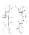
- Fig. 1 shows a fuel line system 1, which consists of at least one flow line 2 and at least one return line 3.
- the fuel line system 1 is in the embodiment shown in FIG. 1 in three sections 4, 5, 6 divided.
- the front and rear sections 4 and 6 are usually considered one Hose formed, which can be an elastomer hose, for example.
- the middle section 5 serves to cool, in particular, that in the return line 3 contained fuel.
- the middle section 5 is at the bottom or Floor panel 7 of the body 8 of a motor vehicle, for example via clips 9 and 10 attached acoustically decoupled.
- the fuel line system 1 promotes the Fuel from a fuel tank 11 via the feed line 2 to an engine 12.
- the fuel not used by the engine 12 is very hot and is over the Return line 3 conveyed back to the fuel tank 11.
- the middle section 5 is provided with a heat-conductive surface enlargement 13. Embodiments Such a surface enlargement 13 are shown in FIGS. 2 to 5 shown.
- FIG. 2 shows an embodiment of a fuel line system 1, in which the return line 3 as a surface enlargement 13 can be switched on and off Additional line 14 is installed.
- the additional line 14 is switched on or off for example via a temperature-controlled valve 15.
- the additional line 14 is like the middle section 5 on the underside 7 of the body arranged a motor vehicle.
- the additional line 14 is cooled by giving off the heat to the ambient air, the giving off by the flow around the additional line 14 is accelerated.
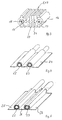
- FIG. 3 is a perspective sectional view of a surface enlargement 13 shown, which is designed as an extruded tube profile 16.
- the extruded tube profile 16 has two lines 17 and 18, in which the fuel is forward or runs back.
- In the return line 18 is a second line 19 with a smaller one Cross section arranged in contact with the surface enlargement 13.
- the line 18, 19 is connected via a temperature-dependent valve, the Fuel then through both lines 18, 19 or only through the larger line 18 can flow.
- the surface enlargement 13 of FIG. 3 consists of longitudinal ribs 20, which are integrally formed on a crossbar 21.
- the supply and return lines 17, 18, 19 are as one common profile and in another embodiment as separate profiles manufactured. 3 also shows in relation to the lines 18 and 19, that the surface enlargement 13 by increasing the cross section of the normal line 19 can be done in relation to the enlarged line 18.
- the surface enlargement 13 has the cross-sectional increase the further effect that the fuel in the fuel line with a larger cross section flows more slowly through the line so that the fuel stays in the vehicle is increased in the cooling section 5 and thus more heat to the environment can be emitted.
- the connections from the extruded tube profile 16 to the front and rear sections 4 and 5 takes place via pressed or screwed Support.
- FIGS. 4 and 5 show an embodiment of the cooling section 5, in which the heat-conductive lines 22 and 23 are surrounded by a heat-conducting plate 24 or more heat-conducting plates 25, 26, 27.
- the heat conducting plates 24; 25, 26, 27 can simultaneously be used as a c w value cover for the underside 7 of the body 8 of a motor vehicle.
- the heat conducting plates 24; 25, 26, 27 and the lines 22, 23 arranged therein are acoustically decoupled attached to the body 8.
Landscapes
- Engineering & Computer Science (AREA)
- Physics & Mathematics (AREA)
- Mechanical Engineering (AREA)
- General Engineering & Computer Science (AREA)
- Thermal Sciences (AREA)
- Geometry (AREA)
- Chemical & Material Sciences (AREA)
- Combustion & Propulsion (AREA)
- Cooling, Air Intake And Gas Exhaust, And Fuel Tank Arrangements In Propulsion Units (AREA)
Description
- Fig. 1
- eine Prinzipdarstellung von der Seite eines Kraftstoffleitungssystems, das eine wärmeleitfähige Oberflächenvergrößerung aufweist, die an der Unterseite einer Karosserie eines Kraftfahrzeuges befestigt ist,
- Fig. 2
- eine Prinzipdarstellung eines Kraftstoffleitungssystems, bei dem in die Rücklaufleitung über ein temperaturgesteuertes Ventil eine zusätzliche Leitung zu- oder abschaltbar ist,
- Fig. 3
- eine perspektivische Schnittansicht einer Strangpreßprofilrohrleitung mit einer Vorlaufleitung und zwei unterschiedlich großen Rücklaufleitungen,
- Fig. 4
- eine perspektivische Schnittansicht einer Vorlauf- und einer Rücklaufleitung, die in einem Wärmeleitblech befestigt sind und
- Fig. 5
- eine perspektivische Schnittansicht einer Vorlauf- und einer Rücklaufleitung, an denen jeweils Abschnitte eines Wärmeleitbleches angeordnet sind.
Claims (3)
- Kraftfahrzeug mit einem Kraftstoffleitungssystem (1), das mindestens eine Vorlauf- und mindestens eine Rücklaufleitung (2, 3) aufweist, die jeweils zwischen einem Motor (12) und einem Kraftstoffbehälter (11) des Kraftfahrzeuges angeordnet sind, wobei das Kraftstoffleitungssystem (1) mindestens einen Abschnitt (5) mit einer wärmeleitfähigen Oberflächenvergrößerung (13) zur Luftkühlung des Kraftstoffes aufweist, wobei die Oberflächenvergrößerung (13) in Abhängigkeit von den fahrzeugspezifischen Werten so bemessen ist, daß der in den Kraftstoffbehälter (11) zurückfließende Kraftstoff auf eine zulässige Betriebstemperatur abgekühlt ist, und wobei die wärmeleitfähige Oberflächenvergrößerung (13) aus von der Leitung (17, 18, 19) abstehende Elemente (20, 21) besteht, die aus einem Leichtmetall hergestellt sind, dadurch gekennzeichnet, daß das Kraftstoffleitungssystem (1) an der Außenoberfläche der Karosserie (8) des Kraftfahrzeuges, insbesondere am Bodenblech (7), akustisch entkoppelt angeordnet ist und
daß die Oberflächenvergrößerung (13) alternativ oder zusätzlich durch eine Zusatzleitung (14) und/oder durch eine Querschnittserhöhung der Leitung (18, 19) und/oder durch Wärmeleitbleche (24; 25, 26, 27) gebildet ist. - Kraftstoffleitungssystem nach Anspruch 1,
dadurch gekennzeichnet, daß die als Oberflächenvergrößerung (13) dienende Leitung (14, 18) temperaturabhängig zu- oder abschaltbar ist. - Kraftstoffleitungssystem nach Anspruch 1,
dadurch gekennzeichnet, daß das Wärmeleitblech (24; 25, 26, 27) aus einem oder mehreren Blechen gebildet ist.
Applications Claiming Priority (2)
| Application Number | Priority Date | Filing Date | Title |
|---|---|---|---|
| DE19619934A DE19619934A1 (de) | 1996-05-17 | 1996-05-17 | Kraftstoffleitungssystem |
| DE19619934 | 1996-05-17 |
Publications (4)
| Publication Number | Publication Date |
|---|---|
| EP0807756A2 EP0807756A2 (de) | 1997-11-19 |
| EP0807756A3 EP0807756A3 (de) | 1998-04-01 |
| EP0807756B1 true EP0807756B1 (de) | 2000-07-05 |
| EP0807756B2 EP0807756B2 (de) | 2005-03-16 |
Family
ID=7794584
Family Applications (1)
| Application Number | Title | Priority Date | Filing Date |
|---|---|---|---|
| EP97104608A Expired - Lifetime EP0807756B2 (de) | 1996-05-17 | 1997-03-18 | Kraftstoffleitungssystem |
Country Status (2)
| Country | Link |
|---|---|
| EP (1) | EP0807756B2 (de) |
| DE (2) | DE19619934A1 (de) |
Cited By (1)
| Publication number | Priority date | Publication date | Assignee | Title |
|---|---|---|---|---|
| US6536516B2 (en) | 2000-12-21 | 2003-03-25 | Long Manufacturing Ltd. | Finned plate heat exchanger |
Families Citing this family (14)
| Publication number | Priority date | Publication date | Assignee | Title |
|---|---|---|---|---|
| DE19729857A1 (de) * | 1997-07-11 | 1999-01-14 | Volkswagen Ag | Kraftfahrzeug mit Unterbodenwärmetauscher |
| FR2774462B1 (fr) * | 1998-01-30 | 2000-04-14 | Peugeot | Echangeur refroidisseur de fluide |
| FR2774463A1 (fr) * | 1998-01-30 | 1999-08-06 | Peugeot | Module echangeur refroidisseur de fluide et utilisation du module echangeur refroidisseur |
| FR2774635B1 (fr) * | 1998-02-09 | 2000-04-21 | Valeo Thermique Moteur Sa | Dispositif de refroidissement du carburant d'un moteur de vehicule automobile |
| DE19815167B4 (de) * | 1998-04-04 | 2006-11-23 | Adam Opel Ag | Kraftstoffleitungssystem |
| DK79298A (da) | 1998-06-08 | 1999-12-09 | Norsk Hydro As | Profil for køling af brændstof, en brændstofledning samt en fremgangsmåde til fremstilling heraf |
| DE19916530A1 (de) * | 1999-04-13 | 2000-10-19 | Mannesmann Vdo Ag | Einrichtung zur Versorgung einer Brennkraftmaschine eines Kraftfahrzeuges mit Kraftstoff |
| SE512730C2 (sv) * | 1999-04-22 | 2000-05-08 | Scania Cv Ab | Bränsletank |
| US7011142B2 (en) | 2000-12-21 | 2006-03-14 | Dana Canada Corporation | Finned plate heat exchanger |
| WO2003001135A1 (es) * | 2001-05-01 | 2003-01-03 | Romero Beltran Julian | Intercambiador de calor del tipo placa-tubo |
| CA2392610C (en) | 2002-07-05 | 2010-11-02 | Long Manufacturing Ltd. | Baffled surface cooled heat exchanger |
| CA2425233C (en) | 2003-04-11 | 2011-11-15 | Dana Canada Corporation | Surface cooled finned plate heat exchanger |
| CA2451424A1 (en) | 2003-11-28 | 2005-05-28 | Dana Canada Corporation | Low profile heat exchanger with notched turbulizer |
| DE102016123323B3 (de) * | 2016-12-02 | 2018-03-01 | Eberspächer Climate Control Systems GmbH & Co. KG | Fahrzeug |
Citations (4)
| Publication number | Priority date | Publication date | Assignee | Title |
|---|---|---|---|---|
| US3294148A (en) * | 1966-12-27 | Fuel feeding system for internal combustion engines | ||
| EP0038710A1 (de) * | 1980-04-23 | 1981-10-28 | Barry William Wilder | Kraftstoffkühlvorrichtung für Brennkraftmaschinen |
| DE3800296A1 (de) * | 1988-01-08 | 1989-07-20 | Porsche Ag | Kuehlvorrichtung an einem kraftfahrzeug |
| DE4141689C2 (de) * | 1991-12-18 | 1997-01-30 | Audi Ag | Vorrichtung zur Halterung einer Leitung an einer Wand eines Kraftfahrzeuges |
Family Cites Families (13)
| Publication number | Priority date | Publication date | Assignee | Title |
|---|---|---|---|---|
| US2969110A (en) * | 1959-03-12 | 1961-01-24 | Exxon Research Engineering Co | Fuel delivery system for automotive vehicles |
| FR1479486A (fr) * | 1966-03-14 | 1967-05-05 | Tube à profil spécial pour la constitution d'échangeurs thermiques | |
| CH606958A5 (en) * | 1976-12-02 | 1978-11-30 | Pierre Chuard | Tube and plate heat exchanger unit |
| IT1156963B (it) * | 1978-04-17 | 1987-02-04 | Fiat Veicoli Ind | Sistema per l'alimentazione del combustibile ad un motore a combustione interna |
| DE3153101C2 (de) * | 1981-01-02 | 1985-09-26 | Daimler-Benz Ag, 7000 Stuttgart | Kraftstoffkühler |
| JPS59155564A (ja) * | 1983-02-24 | 1984-09-04 | Toyota Motor Corp | 燃料噴射式エンジンの燃料分配管 |
| DE3704215C2 (de) * | 1987-02-11 | 1995-11-30 | Laengerer & Reich Kuehler | Strangpreßprofilrohr für Wärmeaustauscher |
| DE3735915A1 (de) * | 1987-10-23 | 1989-05-03 | Wieland Werke Ag | Waermeaustauscher |
| DE3740811A1 (de) * | 1987-12-02 | 1989-06-15 | Zdenek Struhovsky | Kraftstoffkuehler fuer eine brennkraftmaschine |
| DE3912534C2 (de) * | 1989-04-17 | 1994-07-14 | Hansa Metallwerke Ag | Benzinkühler |
| JPH0343653A (ja) * | 1989-07-08 | 1991-02-25 | Nippondenso Co Ltd | 燃料冷却装置 |
| JPH04132446U (ja) * | 1991-05-29 | 1992-12-08 | 本田技研工業株式会社 | 自動車のガソリン冷却装置 |
| EP0693171B1 (de) * | 1993-03-29 | 1999-10-27 | Melanesia International Trust Company Limited | Wärmetauscheranordnung |
-
1996
- 1996-05-17 DE DE19619934A patent/DE19619934A1/de not_active Withdrawn
-
1997
- 1997-03-18 DE DE59701962T patent/DE59701962D1/de not_active Expired - Lifetime
- 1997-03-18 EP EP97104608A patent/EP0807756B2/de not_active Expired - Lifetime
Patent Citations (4)
| Publication number | Priority date | Publication date | Assignee | Title |
|---|---|---|---|---|
| US3294148A (en) * | 1966-12-27 | Fuel feeding system for internal combustion engines | ||
| EP0038710A1 (de) * | 1980-04-23 | 1981-10-28 | Barry William Wilder | Kraftstoffkühlvorrichtung für Brennkraftmaschinen |
| DE3800296A1 (de) * | 1988-01-08 | 1989-07-20 | Porsche Ag | Kuehlvorrichtung an einem kraftfahrzeug |
| DE4141689C2 (de) * | 1991-12-18 | 1997-01-30 | Audi Ag | Vorrichtung zur Halterung einer Leitung an einer Wand eines Kraftfahrzeuges |
Non-Patent Citations (1)
| Title |
|---|
| Ersatzteilkatalog Volvo 760 series; 1988 and drawings PV200 41611 and PV233 45988 * |
Cited By (1)
| Publication number | Priority date | Publication date | Assignee | Title |
|---|---|---|---|---|
| US6536516B2 (en) | 2000-12-21 | 2003-03-25 | Long Manufacturing Ltd. | Finned plate heat exchanger |
Also Published As
| Publication number | Publication date |
|---|---|
| DE59701962D1 (de) | 2000-08-10 |
| DE19619934A1 (de) | 1997-11-20 |
| EP0807756A2 (de) | 1997-11-19 |
| EP0807756A3 (de) | 1998-04-01 |
| EP0807756B2 (de) | 2005-03-16 |
Similar Documents
| Publication | Publication Date | Title |
|---|---|---|
| EP0807756B1 (de) | Kraftstoffleitungssystem | |
| DE69919434T2 (de) | Kühleranordnung eines Kraftfahrzeuges | |
| EP0861368B1 (de) | Kühlkreislauf einer brennkraftmaschine sowie verfahren zum betrieb des kühlkreislaufes | |
| DE60317179T2 (de) | Beheiztes und gekühltes Lenkrad | |
| EP0777585B1 (de) | Kfz-wärmetauscher | |
| DE202019102689U1 (de) | Wärmetauscher und Kreislaufsystem zum Temperieren | |
| DE102019205575A1 (de) | Vorrichtung zur Kühlung einer Fahrzeugbatterie | |
| DE4431107C1 (de) | Wärmetauscheranordnung zur Beheizung der Kabine von Kraftfahrzeugen mit der Abwärme des Antriebsmotors | |
| EP0890810B1 (de) | Kraftfahrzeug mit Unterbodenwärmetauscher | |
| DE4438093C1 (de) | Be- und Entlüftungseinrichtung für Teile von Kraftfahrzeugmotoren | |
| DE10393269T5 (de) | Kühlvorrichtung für ein motorisiertes Fahrzeug | |
| DE2606507A1 (de) | Klimaanlage | |
| EP1083072B1 (de) | Kühleinrichtung für eine Brennkraftmaschine | |
| DE10328458A1 (de) | Niedrigtemperatur-Kühler für ein Kraftfahrzeug zur Kühlung mehrerer Bauteile | |
| DE1655069A1 (de) | Waermeaustauscher fuer die Heizung und Kuehlung von Fahrzeugen | |
| DE102007008884A1 (de) | Heizkörper | |
| DE102005019578A1 (de) | Vorrichtung zum Heizen durch Fluidzirkulation | |
| DE3800296A1 (de) | Kuehlvorrichtung an einem kraftfahrzeug | |
| DE102006007777B3 (de) | Kombiniertes Heizungs-/Warmwassersystem für ein Fahrzeug | |
| DE102019204720A1 (de) | Vorrichtung zur Klimatisierung eines Kraftfahrzeuginnenraums, Verdampfer für einen Kältemittelkreislauf, Verfahren zum Betreiben einer Klimatisierungsvorrichtung für ein Kraftfahrzeug und Verfahren zur Klimatisierung eines Kraftfahrzeuginnenraums | |
| EP1241425B1 (de) | Wärmetauscher, insbesondere Kühlersystem für Verbrennungsmotoren | |
| DE102007024038A1 (de) | Wärmetauscher | |
| DE3333940A1 (de) | Vorrichtung zum erwaermen einer waschfluessigkeit fuer die fensterwaschanlage von kraftfahrzeugen | |
| DE60309828T2 (de) | Heizanlage | |
| DE2719616A1 (de) | Einrichtung zur beheizung des fahrgastraumes von kraftfahrzeugen |
Legal Events
| Date | Code | Title | Description |
|---|---|---|---|
| PUAI | Public reference made under article 153(3) epc to a published international application that has entered the european phase |
Free format text: ORIGINAL CODE: 0009012 |
|
| AK | Designated contracting states |
Kind code of ref document: A2 Designated state(s): DE FR GB IT |
|
| PUAL | Search report despatched |
Free format text: ORIGINAL CODE: 0009013 |
|
| AK | Designated contracting states |
Kind code of ref document: A3 Designated state(s): DE FR GB IT |
|
| 17P | Request for examination filed |
Effective date: 19980915 |
|
| 17Q | First examination report despatched |
Effective date: 19990120 |
|
| GRAG | Despatch of communication of intention to grant |
Free format text: ORIGINAL CODE: EPIDOS AGRA |
|
| GRAG | Despatch of communication of intention to grant |
Free format text: ORIGINAL CODE: EPIDOS AGRA |
|
| GRAH | Despatch of communication of intention to grant a patent |
Free format text: ORIGINAL CODE: EPIDOS IGRA |
|
| RTI1 | Title (correction) |
Free format text: FUEL CONDUIT |
|
| 17Q | First examination report despatched |
Effective date: 19990120 |
|
| RIN1 | Information on inventor provided before grant (corrected) |
Inventor name: CHRISTIAN, TREML Inventor name: GUENTHER, TUSCHL |
|
| GRAH | Despatch of communication of intention to grant a patent |
Free format text: ORIGINAL CODE: EPIDOS IGRA |
|
| GRAA | (expected) grant |
Free format text: ORIGINAL CODE: 0009210 |
|
| AK | Designated contracting states |
Kind code of ref document: B1 Designated state(s): DE FR GB IT |
|
| GBT | Gb: translation of ep patent filed (gb section 77(6)(a)/1977) |
Effective date: 20000705 |
|
| REF | Corresponds to: |
Ref document number: 59701962 Country of ref document: DE Date of ref document: 20000810 |
|
| ET | Fr: translation filed | ||
| ITF | It: translation for a ep patent filed | ||
| PLBQ | Unpublished change to opponent data |
Free format text: ORIGINAL CODE: EPIDOS OPPO |
|
| PLBI | Opposition filed |
Free format text: ORIGINAL CODE: 0009260 |
|
| 26 | Opposition filed |
Opponent name: NORSK HYDRO ASA Effective date: 20010402 Opponent name: AUDI AG Effective date: 20010331 |
|
| PLBF | Reply of patent proprietor to notice(s) of opposition |
Free format text: ORIGINAL CODE: EPIDOS OBSO |
|
| PLBF | Reply of patent proprietor to notice(s) of opposition |
Free format text: ORIGINAL CODE: EPIDOS OBSO |
|
| REG | Reference to a national code |
Ref country code: GB Ref legal event code: IF02 |
|
| PLBC | Reply to examination report in opposition received |
Free format text: ORIGINAL CODE: EPIDOSNORE3 |
|
| PUAH | Patent maintained in amended form |
Free format text: ORIGINAL CODE: 0009272 |
|
| STAA | Information on the status of an ep patent application or granted ep patent |
Free format text: STATUS: PATENT MAINTAINED AS AMENDED |
|
| 27A | Patent maintained in amended form |
Effective date: 20050316 |
|
| AK | Designated contracting states |
Kind code of ref document: B2 Designated state(s): DE FR GB IT |
|
| GBTA | Gb: translation of amended ep patent filed (gb section 77(6)(b)/1977) | ||
| ET3 | Fr: translation filed ** decision concerning opposition | ||
| PLAB | Opposition data, opponent's data or that of the opponent's representative modified |
Free format text: ORIGINAL CODE: 0009299OPPO |
|
| PGFP | Annual fee paid to national office [announced via postgrant information from national office to epo] |
Ref country code: DE Payment date: 20140319 Year of fee payment: 18 |
|
| PGFP | Annual fee paid to national office [announced via postgrant information from national office to epo] |
Ref country code: IT Payment date: 20140327 Year of fee payment: 18 |
|
| PGFP | Annual fee paid to national office [announced via postgrant information from national office to epo] |
Ref country code: GB Payment date: 20140327 Year of fee payment: 18 |
|
| PGFP | Annual fee paid to national office [announced via postgrant information from national office to epo] |
Ref country code: FR Payment date: 20140327 Year of fee payment: 18 |
|
| REG | Reference to a national code |
Ref country code: DE Ref legal event code: R119 Ref document number: 59701962 Country of ref document: DE |
|
| GBPC | Gb: european patent ceased through non-payment of renewal fee |
Effective date: 20150318 |
|
| PG25 | Lapsed in a contracting state [announced via postgrant information from national office to epo] |
Ref country code: IT Free format text: LAPSE BECAUSE OF NON-PAYMENT OF DUE FEES Effective date: 20150318 |
|
| REG | Reference to a national code |
Ref country code: FR Ref legal event code: ST Effective date: 20151130 |
|
| PG25 | Lapsed in a contracting state [announced via postgrant information from national office to epo] |
Ref country code: GB Free format text: LAPSE BECAUSE OF NON-PAYMENT OF DUE FEES Effective date: 20150318 Ref country code: DE Free format text: LAPSE BECAUSE OF NON-PAYMENT OF DUE FEES Effective date: 20151001 |
|
| PG25 | Lapsed in a contracting state [announced via postgrant information from national office to epo] |
Ref country code: FR Free format text: LAPSE BECAUSE OF NON-PAYMENT OF DUE FEES Effective date: 20150331 |