EP0807756A2 - Kraftstoffleitungssystem - Google Patents
Kraftstoffleitungssystem Download PDFInfo
- Publication number
- EP0807756A2 EP0807756A2 EP97104608A EP97104608A EP0807756A2 EP 0807756 A2 EP0807756 A2 EP 0807756A2 EP 97104608 A EP97104608 A EP 97104608A EP 97104608 A EP97104608 A EP 97104608A EP 0807756 A2 EP0807756 A2 EP 0807756A2
- Authority
- EP
- European Patent Office
- Prior art keywords
- fuel
- line
- line system
- surface enlargement
- heat
- Prior art date
- Legal status (The legal status is an assumption and is not a legal conclusion. Google has not performed a legal analysis and makes no representation as to the accuracy of the status listed.)
- Granted
Links
Images

Classifications
-
- F—MECHANICAL ENGINEERING; LIGHTING; HEATING; WEAPONS; BLASTING
- F28—HEAT EXCHANGE IN GENERAL
- F28D—HEAT-EXCHANGE APPARATUS, NOT PROVIDED FOR IN ANOTHER SUBCLASS, IN WHICH THE HEAT-EXCHANGE MEDIA DO NOT COME INTO DIRECT CONTACT
- F28D7/00—Heat-exchange apparatus having stationary tubular conduit assemblies for both heat-exchange media, the media being in contact with different sides of a conduit wall
-
- F—MECHANICAL ENGINEERING; LIGHTING; HEATING; WEAPONS; BLASTING
- F02—COMBUSTION ENGINES; HOT-GAS OR COMBUSTION-PRODUCT ENGINE PLANTS
- F02M—SUPPLYING COMBUSTION ENGINES IN GENERAL WITH COMBUSTIBLE MIXTURES OR CONSTITUENTS THEREOF
- F02M31/00—Apparatus for thermally treating combustion-air, fuel, or fuel-air mixture
- F02M31/20—Apparatus for thermally treating combustion-air, fuel, or fuel-air mixture for cooling
-
- F—MECHANICAL ENGINEERING; LIGHTING; HEATING; WEAPONS; BLASTING
- F28—HEAT EXCHANGE IN GENERAL
- F28D—HEAT-EXCHANGE APPARATUS, NOT PROVIDED FOR IN ANOTHER SUBCLASS, IN WHICH THE HEAT-EXCHANGE MEDIA DO NOT COME INTO DIRECT CONTACT
- F28D1/00—Heat-exchange apparatus having stationary conduit assemblies for one heat-exchange medium only, the media being in contact with different sides of the conduit wall, in which the other heat-exchange medium is a large body of fluid, e.g. domestic or motor car radiators
- F28D1/02—Heat-exchange apparatus having stationary conduit assemblies for one heat-exchange medium only, the media being in contact with different sides of the conduit wall, in which the other heat-exchange medium is a large body of fluid, e.g. domestic or motor car radiators with heat-exchange conduits immersed in the body of fluid
- F28D1/04—Heat-exchange apparatus having stationary conduit assemblies for one heat-exchange medium only, the media being in contact with different sides of the conduit wall, in which the other heat-exchange medium is a large body of fluid, e.g. domestic or motor car radiators with heat-exchange conduits immersed in the body of fluid with tubular conduits
- F28D1/053—Heat-exchange apparatus having stationary conduit assemblies for one heat-exchange medium only, the media being in contact with different sides of the conduit wall, in which the other heat-exchange medium is a large body of fluid, e.g. domestic or motor car radiators with heat-exchange conduits immersed in the body of fluid with tubular conduits the conduits being straight
-
- F—MECHANICAL ENGINEERING; LIGHTING; HEATING; WEAPONS; BLASTING
- F28—HEAT EXCHANGE IN GENERAL
- F28F—DETAILS OF HEAT-EXCHANGE AND HEAT-TRANSFER APPARATUS, OF GENERAL APPLICATION
- F28F1/00—Tubular elements; Assemblies of tubular elements
- F28F1/10—Tubular elements and assemblies thereof with means for increasing heat-transfer area, e.g. with fins, with projections, with recesses
- F28F1/12—Tubular elements and assemblies thereof with means for increasing heat-transfer area, e.g. with fins, with projections, with recesses the means being only outside the tubular element
- F28F1/14—Tubular elements and assemblies thereof with means for increasing heat-transfer area, e.g. with fins, with projections, with recesses the means being only outside the tubular element and extending longitudinally
- F28F1/22—Tubular elements and assemblies thereof with means for increasing heat-transfer area, e.g. with fins, with projections, with recesses the means being only outside the tubular element and extending longitudinally the means having portions engaging further tubular elements
-
- F—MECHANICAL ENGINEERING; LIGHTING; HEATING; WEAPONS; BLASTING
- F28—HEAT EXCHANGE IN GENERAL
- F28D—HEAT-EXCHANGE APPARATUS, NOT PROVIDED FOR IN ANOTHER SUBCLASS, IN WHICH THE HEAT-EXCHANGE MEDIA DO NOT COME INTO DIRECT CONTACT
- F28D21/00—Heat-exchange apparatus not covered by any of the groups F28D1/00 - F28D20/00
- F28D2021/0019—Other heat exchangers for particular applications; Heat exchange systems not otherwise provided for
- F28D2021/008—Other heat exchangers for particular applications; Heat exchange systems not otherwise provided for for vehicles
- F28D2021/0087—Fuel coolers
-
- Y—GENERAL TAGGING OF NEW TECHNOLOGICAL DEVELOPMENTS; GENERAL TAGGING OF CROSS-SECTIONAL TECHNOLOGIES SPANNING OVER SEVERAL SECTIONS OF THE IPC; TECHNICAL SUBJECTS COVERED BY FORMER USPC CROSS-REFERENCE ART COLLECTIONS [XRACs] AND DIGESTS
- Y02—TECHNOLOGIES OR APPLICATIONS FOR MITIGATION OR ADAPTATION AGAINST CLIMATE CHANGE
- Y02T—CLIMATE CHANGE MITIGATION TECHNOLOGIES RELATED TO TRANSPORTATION
- Y02T10/00—Road transport of goods or passengers
- Y02T10/10—Internal combustion engine [ICE] based vehicles
- Y02T10/12—Improving ICE efficiencies
Definitions
- the invention relates to a fuel line system according to the preamble of claim 1.
- extruded profile tube for heat exchangers which is composed of at least two profile halves, which are tightly connected to one another along two outer longitudinal edges.
- the extruded profile tube can be provided on the inside and / or outside with elements that enlarge the heat exchange surface. These elements can e.g. B. consist of longitudinal ribs or preferably in longitudinal rows successive individual tongues, wings or projections, which are formed by cuts in longitudinal ribs and by bending, turning or the like.
- holding means can be provided on the extruded profile tube, which for fastening elements increasing the heat exchange surface, for. B. zigzag-shaped fins, and which also ensure good heat conduction from the tube to the fins.
- the extruded profile tube is especially for heat exchangers, for. B. for radiators of motor vehicles. In these heat exchangers, the cooling water of the engine is cooled by the wind and / or by a fan.
- the object of the invention is to provide a fuel line system in which fuel cooling is possible in a simple manner.
- the fuel in the fuel lines is air-cooled in that the fuel lines and at least the return line or return lines are provided with a thermally conductive surface enlargement, which is formed only in sections.
- the heat-conductive surface enlargement is arranged on the outer surface of the body of a motor vehicle, in particular on the floor panel.
- the surface enlargement takes place in one embodiment by the formation of additional surfaces, i. H. components such as ribs that protrude from the fuel line and / or heat conducting plates that are connected to the fuel line.
- additional surfaces i. H. components such as ribs that protrude from the fuel line and / or heat conducting plates that are connected to the fuel line.
- the surface area is increased by increasing the line length of the fuel line.
- the surface can be enlarged in that the fuel line has a larger cross section. Further embodiments result from combinations of the aforementioned possibilities.
- the increase in surface area according to the invention is such that the temperature of the fuel flowing back via the return line has cooled down to such an extent that the permissible continuous operating temperature of the fuel tank and / or its installation units is not exceeded.
- the section-wise formation of a heat-conductive surface enlargement in the form of extruded profile pipes has the advantage that inexpensive goods by the meter can be used.
- a design is possible that leads to an improvement in the c w value.
- the fuel line system is designed in such a way that the cooling can be switched on or off as required by the surface enlargement according to the invention. If the surface area according to the invention is increased by a longer line length, then a valve switched by the fuel temperature is installed in the fuel line, which enables the line extension to be switched on or off.
- a line with a smaller cross section it is possible for a line with a smaller cross section to be formed within the fuel line. Switching from the line with the larger cross-section to the line with the smaller cross-section and vice versa also takes place, for example, via a thermostatic valve.
- the fuel line system according to the invention is acoustically decoupled from the body of the motor vehicle by a corresponding type of fastening.
- the fuel line system 1 shows a fuel line system 1, which consists of at least one supply line 2 and at least one return line 3.
- the fuel line system 1 is divided into three sections 4, 5, 6.
- the front and rear sections 4 and 6 are generally designed as a tube, which can be an elastomer tube, for example.
- the middle section 5 serves to cool the fuel contained in the return line 3 in particular.
- the middle section 5 is fastened acoustically decoupled to the underside or the floor panel 7 of the body 8 of a motor vehicle, for example via clips 9 and 10.
- the fuel line system 1 conveys the fuel from a fuel tank 11 via the supply line 2 to an engine 12.
- the fuel not consumed by the engine 12 is very hot and is returned to the fuel tank 11 via the return line 3.
- the middle section 5 is provided with a heat-conductive surface enlargement 13. Embodiments of such a surface enlargement 13 are shown in FIGS. 2 to 5.
- FIG. 2 shows an embodiment of a fuel line system 1 in which an additional line 14 which can be switched on and off is installed in the return line 3 as a surface enlargement 13.
- the additional line 14 is switched on or off, for example, via a temperature-controlled valve 15.
- the additional line 14, like the central section 5, is arranged on the underside 7 of the body of a motor vehicle. The cooling of the additional line 14 takes place by releasing the heat into the ambient air, the heat being released being accelerated by the flow of air around the additional line 14.
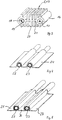
- FIG. 3 shows a perspective sectional view of a surface enlargement 13, which is designed as an extruded tube profile 16.
- the extruded tube profile 16 has two lines 17 and 18, in which the fuel runs forwards or backwards.
- a second line 19 with a smaller cross section is arranged in contact with the surface enlargement 13.
- the lines 17, 19 initially the cold fuel flows until the fuel has reached its operating temperature.
- the line 18 is connected via a temperature-dependent valve, the fuel then being able to flow through both lines 18, 19 or only through the larger line 18.
- the surface enlargement 13 of Fig. 3 consists of longitudinal ribs 20 which are integrally formed on a crossbar 21.
- the supply and return lines 17, 18, 19 are made as a common profile and in another embodiment as separate profiles. From Fig. 3 also shows with respect to the lines 18 and 19 that the increase in surface area 13 can be achieved by increasing the cross section of the normal line 19 in relation to the enlarged line 18. In addition to the surface enlargement 13, the cross-sectional increase has the further effect that the fuel in the fuel line flows more slowly through the line with a larger cross-section, so that the length of time of the fuel in the cooling section 5 is increased and thus more heat can be radiated to the environment .
- the connections from the extruded tube profile 16 to the front and rear sections 4 and 5 are made by means of pressed-in or screwed-in connectors.
- FIGS. 4 and 5 show an embodiment of the cooling section 5, in which the heat-conducting lines 22 and 23 are surrounded by a heat-conducting plate 24 or more heat-conducting plates 25, 26, 27.
- the heat conducting plates 24; 25, 26, 27 can simultaneously be used as a c w value cover for the underside 7 of the body 8 of a motor vehicle.
- the heat conducting plates 24; 25, 26, 27 and the lines 22, 23 arranged therein are acoustically decoupled attached to the body 8.
Landscapes
- Engineering & Computer Science (AREA)
- Physics & Mathematics (AREA)
- Mechanical Engineering (AREA)
- General Engineering & Computer Science (AREA)
- Thermal Sciences (AREA)
- Geometry (AREA)
- Chemical & Material Sciences (AREA)
- Combustion & Propulsion (AREA)
- Cooling, Air Intake And Gas Exhaust, And Fuel Tank Arrangements In Propulsion Units (AREA)
Abstract
Description
- Die Erfindung betrifft ein Kraftstoffleitungssystem gemäß dem Oberbegriff des Anspruchs 1.
- Aus der DE-OS 37 04 215 ist bereits ein Strangpreßprofilrohr für Wärmeaustauscher bekannt, das aus mindestens zwei Profilhälften zusammengesetzt ist, die entlang zweier äußerer Längsränder dicht miteinander verbunden sind. Das Strangpreßprofilrohr kann innen und/oder außen mit die Wärmeaustauschfläche vergrößernden Elementen versehen sein. Diese Elemente können z. B. aus Längsrippen oder aus vorzugsweise in Längsreihen aufeinanderfolgenden einzelnen Zungen, Flügeln oder Vorsprüngen bestehen, die durch Einschnitte in Längsrippen und durch Abbiegen, Drehen oder dergleichen gebildet werden. Ferner können an dem Strangpreßprofilrohr Haltemittel vorgesehen sein, die zur Befestigung von die Wärmeaustauschfläche vergrößernden Elementen, z. B. zickzackförmigen Lamellen, dienen und die gleichzeitig eine gute Wärmeleitung vom Rohr zur Lamelle gewährleisten. Das Strangpreßprofilrohr ist vor allem für Wärmeaustauscher, z. B. für Kühler von Kraftfahrzeugen, bestimmt. Bei diesen Wärmetauschem wird das Kühlwasser des Motors durch den Fahrtwind und/oder durch einen Ventilator abgekühlt.
- Bei zukünftigen Motoren kann es aufgrund des Einsatzes neuer Techniken zu einer massiven Erhöhung der Kraftstofftemperatur kommen, die beispielsweise 50 % über der bislang maximalen Kraftstofftemperatur liegt. Bei den dann erreichten Kraftstofftemperaturen, die überwiegend oberhalb von 100 °C liegen, kommt es jedoch zu Problemen mit Kraftstoffbehältern aus Kunststoff und/oder den im Kraftstoffbehälter befindlichen Zusatzeinrichtungen, die Kunststoff-Bauteile enthalten. Bisher verwendete Systeme zur Kraftstoffkühlung sind jedoch aufwendig und teuer.
- Aufgabe der Erfindung ist es, ein Kraftstoffleitungssystem zu schaffen, bei dem in einfacher Weise eine Kraftstoffkühlung möglich ist.
- Diese Aufgabe wird durch die Merkmale des Anspruchs 1 gelöst.
- Bei dem erfindungsgemäßen Kraftstoffleitungssystem erfolgt eine Luftkühlung des in den Kraftstoffleitungen befindlichen Kraftstoffes dadurch, daß die Kraftstoffleitungen und dabei mindestens die Rücklaufleitung bzw. Rücklaufleitungen mit einer wärmeleitfähigen Oberflächenvergrößerung versehen ist, die nur abschnittsweise ausgebildet ist. Die wärmeleitfähige Oberflächenvergrößerung ist an der Außenoberfläche der Karosserie eines Kraftfahrzeuges, insbesondere am Bodenblech, angeordnet.
- Die Oberflächenvergrößerung erfolgt in einer Ausführungsform durch die Ausbildung von Zusatzflächen, d. h. von Bauteilen wie Rippen, die von der Kraftstoffleitung abstehen und/oder von Wärmeleitblechen, die mit der Kraftstoffleitung verbunden sind. In einer anderen Ausführungsform oder zusätzlich erfolgt die Oberflächenvergrößerung dadurch, daß die Leitungslänge der Kraftstoffleitung erhöht ist. In einer weiteren Ausführungsform kann die Oberflächenvergrößerung dadurch erfolgen, daß die Kraftstoffleitung einen größeren Querschnitt aufweist. Weitere Ausführungsformen ergeben sich durch Kombinationen der vorgenannten Möglichkeiten.
- Die erfindungsgemäße Oberflächenvergrößerung ist so bemessen, daß die Temperatur des über die Rücklaufleitung zurückfließenden Kraftstoffes so weit abgekühlt ist, daß die zulässige Dauerbetriebstemperatur des Kraftstoffbehälters und/oder dessen Einbaueinheiten nicht überschritten wird.
- Die abschnittsweise Ausbildung einer wärmeleitfähigen Oberflächenvergrößerung in Form von Strangpreßprofilrohren hat den Vorteil, daß kostengünstige Meterware verwendet werden kann. Bei der Verwendung von Wärmeleitblechen ist eine Gestaltung möglich, die zu einer Verbesserung des cw-Wertes führt.
- In einer weiteren Ausführungsform ist das Kraftstoffleitungssystem so gestaltet, daß die Kühlung über die erfindungsgemäße Oberflächenvergrößerung je nach Bedarf zu- oder abgeschaltet werden kann. Erfolgt die erfindungsgemäße Oberflächenvergrößerung durch eine größere Leitungslänge, dann ist in der Kraftstoffleitung ein durch die Kraftstoff-Temperatur geschaltetes Ventil eingebaut, das eine Zuschaltung oder Abschaltung der Leitungsverlängerung ermöglicht. In einer anderen Ausführungsform ist es möglich, daß innerhalb der Kraftstoffleitung eine Leitung mit einem kleineren Querschnitt ausgebildet ist. Die Umschaltung von der Leitung mit dem größeren Querschnitt auf die Leitung mit dem kleineren Querschnitt und umgekehrt erfolgt beispielsweise ebenfalls über ein Thermostat-Ventil.
- Aus akustischen Gründen ist es vorteilhaft, wenn das erfindungsgemäße Kraftstoffleitungssystem durch eine entsprechende Befestigungsart akustisch von der Karosserie des Kraftfahrzeuges entkoppelt ist.
- Ausführungsformen der Erfindung werden nachstehend anhand der Zeichnungen beispielshalber beschrieben. Dabei zeigen:
- Fig. 1
- eine Prinzipdarstellung von der Seite eines Kraftstoffleitungssystems, das eine wärmeleitfähige Oberflächenvergrößerung aufweist, die an der Unterseite einer Karosserie eines Kraftfahrzeuges befestigt ist,
- Fig. 2
- eine Prinzipdarstellung eines Kraftstoffleitungssystems, bei dem in die Rücklaufleitung über ein temperaturgesteuertes Ventil eine zusätzliche Leitung zu- oder abschaltbar ist,
- Fig. 3
- eine perspektivische Schnittansicht einer Strangpreßprofilrohrleitung mit einer Vorlaufleitung und zwei unterschiedlich großen Rücklaufleitungen,
- Fig. 4
- eine perspektivische Schnittansicht einer Vorlauf- und einer Rücklaufleitung, die in einem Wärmeleitblech befestigt sind und
- Fig. 5
- eine perspektivische Schnittansicht einer Vorlauf- und einer Rücklaufleitung, an denen jeweils Abschnitte eines Wärmeleitbleches angeordnet sind.
- Die Fig. 1 zeigt ein Kraftstoffleitungssystem 1, das aus mindestens einer Vorlaufleitung 2 und mindestens einer Rücklaufleitung 3 besteht. Das Kraftstoffleitungssystem 1 ist in der in der Fig. 1 dargestellten Ausführungsform in drei Abschnitte 4, 5, 6 unterteilt. Der vordere und hintere Abschnitt 4 und 6 ist in der Regel als ein Schlauch ausgebildet, der beispielsweise ein Elastomerschlauch sein kann. Der mittlere Abschnitt 5 dient zur Kühlung insbesondere des in der Rücklaufleitung 3 enthaltenen Kraftstoffes. Der mittlere Abschnitt 5 ist an der Unterseite bzw. dem Bodenblech 7 der Karosserie 8 eines Kraftfahrzeuges beispielsweise über Klipse 9 und 10 akustisch entkoppelt befestigt. Das Kraftstoffleitungssystem 1 fördert den Kraftstoff aus einem Kraftstoffbehälter 11 über die Vorlaufleitung 2 zu einem Motor 12. Der nicht vom Motor 12 verbrauchte Kraftstoff ist sehr heiß und wird über die Rücklaufleitung 3 zum Kraftstoffbehälter 11 zurückbefördert. Der mittlere Abschnitt 5 ist mit einer wärmeleitfähigen Oberflächenvergrößerung 13 versehen. Ausführungsformen einer solchen Oberflächenvergrößerung 13 sind in den Fig. 2 bis 5 dargestellt.
- Die Fig. 2 zeigt eine Ausführungsform eines Kraftstoffleitungssystems 1, bei dem in die Rücklaufleitung 3 als Oberflächenvergrößerung 13 eine zu- und abschaltbare Zusatzleitung 14 eingebaut ist. Die Zu- oder Abschaltung der Zusatzleitung 14 erfolgt beispielsweise über ein temperaturabhängig angesteuertes Ventil 15. Die Zusatzleitung 14 ist wie der mittlere Abschnitt 5 an der Unterseite 7 der Karosserie eines Kraftfahrzeuges angeordnet. Die Abkühlung der Zusatzleitung 14 erfolgt durch Abgabe der Wärme an die Umgebungsluft, wobei die Wärmeabgabe durch das Umströmen der Zusatzleitung 14 mit dem Fahrtwind beschleunigt ist.
- In der Fig. 3 ist eine perspektivische Schnittansicht einer Oberflächenvergrößerung 13 dargestellt, die als ein Strangpreßrohrprofil 16 ausgebildet ist. Das Strangpreßrohrprofil 16 weist zwei Leitungen 17 und 18 auf, in denen der Kraftstoff vor- oder zurückläuft. In der Rücklaufleitung 18 ist eine zweite Leitung 19 mit einem kleineren Querschnitt in Kontakt mit der Oberflächenvergrößerung 13 angeordnet. Durch die Leitungen 17, 19 strömt zunächst der kalte Kraftstoff, bis der Kraftstoff seine Betriebstemperatur erreicht hat. Dann wird, wie bei der Ausführungsform der Fig. 2, über ein temperaturabhängiges Ventil die Leitung 18 dazugeschaltet, wobei der Kraftstoff dann durch beide Leitungen 18, 19 oder nur durch die größere Leitung 18 fließen kann. Die Oberflächenvergrößerung 13 der Fig. 3 besteht aus Längsrippen 20, die einstückig an einem Quersteg 21 ausgebildet sind.
- In einer Ausführungsform sind die Vor- und Rücklaufleitungen 17, 18, 19 als ein gemeinsames Profil und in einer anderen Ausführungsform als getrennte Profile hergestellt. Aus der Fig. 3 geht in bezug auf die Leitungen 18 und 19 ferner hervor, daß die Oberflächenvergrößerung 13 durch eine Querschnittserhöhung der Normalleitung 19 in bezug auf die vergrößerte Leitung 18 erfolgen kann. Neben der Oberflächenvergrößerung 13 hat die Querschnittserhöhung den weiteren Effekt, daß der in der Kraftstoffleitung befindliche Kraftstoff bei einem größeren Querschnitt langsamer durch die Leitung fließt, so daß die Verweildauer des Kraftstoffes in dem Kühlungsabschnitt 5 erhöht ist und somit mehr Wärme an die Umgebung abgestrahlt werden kann. Die Anschlüsse von dem Strangpreßrohrprofil 16 zu den vorderen und hinteren Abschnitten 4 und 5 erfolgt über eingepreßte bzw. eingeschraubte Stutzen.
- Die Fig. 4 und 5 zeigen eine Ausführungsform des Kühlungsabschnittes 5, bei dem die wärmeleitfähigen Leitungen 22 und 23 von einem Wärmeleitblech 24 oder mehreren Wärmeleitblechen 25, 26, 27 umgeben sind. Die Wärmeleitbleche 24; 25, 26, 27 sind gleichzeitig als cw-Wert-Abdeckung der Unterseite 7 der Karosserie 8 eines Kraftfahrzeuges einsetzbar. Wie bei dem Strangpreßrohrprofil 16 sind auch die Wärmeleitbleche 24; 25, 26, 27 sowie die darin angeordneten Leitungen 22, 23 akustisch entkoppelt an der Karosserie 8 befestigt.
Claims (5)
- Kraftstoffleitungssystem mit mindestens einer Vorlauf- und mit mindestens einer Rücklaufleitung, die zwischen einem Motor und einem Kraftstoffbehälter eines Kraftfahrzeuges angeordnet sind,
dadurch gekennzeichnet, daß das Kraftstoffleitungssystem (1) mindestens einen Abschnitt (5) aufweist, bei dem eine wärmeleitfähige Oberflächenvergrößerung (13) ausgebildet ist, daß die Oberflächenvergrößerung (13) in Abhängigkeit von den fahrzeugspezifischen Werten so bemessen ist, daß der in den Kraftstoffbehälter (11) zurückfließende Kraftstoff auf eine zulässige Betriebstemperatur abgekühlt ist. - Kraftstoffleitungssystem nach Anspruch 1,
dadurch gekennzeichnet, daß die Oberflächenvergrößerung (13) durch eine Zusatzleitung (14) und/oder durch eine Querschnittserhöhung der Leitung (18, 19) und/oder durch von der Leitung (17, 18, 19) abstehende Elemente (20, 21) und/oder durch Wärmeleitbleche (24; 25, 26, 27) gebildet ist. - Kraftstoffleitungssystem nach Anspruch 2,
dadurch gekennzeichnet, daß die als Oberflächenvergrößerung (13) dienende Leitung (14, 18) temperaturabhängig zu- oder abschaltbar ist. - Kraftstoffleitungssystem nach Anspruch 2,
dadurch gekennzeichnet, daß das Wärmeleitblech (24; 25, 26, 27) aus einem oder mehreren Blechen gebildet ist. - Kraftstoffleitungssystem nach einem der vorstehenden Ansprüche,
dadurch gekennzeichnet, daß die wärmeleitfähige Oberflächenvergrößerung (13) aus einem Leichtmetall besteht.
Applications Claiming Priority (2)
| Application Number | Priority Date | Filing Date | Title |
|---|---|---|---|
| DE19619934A DE19619934A1 (de) | 1996-05-17 | 1996-05-17 | Kraftstoffleitungssystem |
| DE19619934 | 1996-05-17 |
Publications (4)
| Publication Number | Publication Date |
|---|---|
| EP0807756A2 true EP0807756A2 (de) | 1997-11-19 |
| EP0807756A3 EP0807756A3 (de) | 1998-04-01 |
| EP0807756B1 EP0807756B1 (de) | 2000-07-05 |
| EP0807756B2 EP0807756B2 (de) | 2005-03-16 |
Family
ID=7794584
Family Applications (1)
| Application Number | Title | Priority Date | Filing Date |
|---|---|---|---|
| EP97104608A Expired - Lifetime EP0807756B2 (de) | 1996-05-17 | 1997-03-18 | Kraftstoffleitungssystem |
Country Status (2)
| Country | Link |
|---|---|
| EP (1) | EP0807756B2 (de) |
| DE (2) | DE19619934A1 (de) |
Cited By (11)
| Publication number | Priority date | Publication date | Assignee | Title |
|---|---|---|---|---|
| FR2774462A1 (fr) * | 1998-01-30 | 1999-08-06 | Peugeot | Echangeur refroidisseur de fluide |
| FR2774463A1 (fr) * | 1998-01-30 | 1999-08-06 | Peugeot | Module echangeur refroidisseur de fluide et utilisation du module echangeur refroidisseur |
| WO1999067590A1 (en) * | 1998-06-08 | 1999-12-29 | Norsk Hydro Asa | A flow conduit and means for enlarging the surface thereof to provide cooling, and a fuel pipe, and a method for the manufacture thereof |
| EP0890810A3 (de) * | 1997-07-11 | 2000-04-19 | Volkswagen Aktiengesellschaft | Kraftfahrzeug mit Unterbodenwärmetauscher |
| EP1045131A3 (de) * | 1999-04-13 | 2001-03-07 | Mannesmann VDO Aktiengesellschaft | Einrichtung zur Versorgung einer Brennkraftmaschine eines Kraftfahrzeuges mit Kraftstoff |
| WO2003001135A1 (es) * | 2001-05-01 | 2003-01-03 | Romero Beltran Julian | Intercambiador de calor del tipo placa-tubo |
| US7011142B2 (en) | 2000-12-21 | 2006-03-14 | Dana Canada Corporation | Finned plate heat exchanger |
| US7025127B2 (en) | 2002-07-05 | 2006-04-11 | Dana Canada Corporation | Baffled surface cooled heat exchanger |
| US7182125B2 (en) | 2003-11-28 | 2007-02-27 | Dana Canada Corporation | Low profile heat exchanger with notched turbulizer |
| US7213638B2 (en) | 2003-04-11 | 2007-05-08 | Dana Canada Corporation | Heat exchanger with flow circuiting end caps |
| EP3330116A1 (de) * | 2016-12-02 | 2018-06-06 | Eberspächer Climate Control Systems GmbH & Co. KG. | Fahrzeug |
Families Citing this family (4)
| Publication number | Priority date | Publication date | Assignee | Title |
|---|---|---|---|---|
| FR2774635B1 (fr) * | 1998-02-09 | 2000-04-21 | Valeo Thermique Moteur Sa | Dispositif de refroidissement du carburant d'un moteur de vehicule automobile |
| DE19815167B4 (de) * | 1998-04-04 | 2006-11-23 | Adam Opel Ag | Kraftstoffleitungssystem |
| SE512730C2 (sv) * | 1999-04-22 | 2000-05-08 | Scania Cv Ab | Bränsletank |
| CA2329408C (en) | 2000-12-21 | 2007-12-04 | Long Manufacturing Ltd. | Finned plate heat exchanger |
Family Cites Families (17)
| Publication number | Priority date | Publication date | Assignee | Title |
|---|---|---|---|---|
| US3294148A (en) * | 1966-12-27 | Fuel feeding system for internal combustion engines | ||
| US2969110A (en) * | 1959-03-12 | 1961-01-24 | Exxon Research Engineering Co | Fuel delivery system for automotive vehicles |
| FR1479486A (fr) * | 1966-03-14 | 1967-05-05 | Tube à profil spécial pour la constitution d'échangeurs thermiques | |
| CH606958A5 (en) * | 1976-12-02 | 1978-11-30 | Pierre Chuard | Tube and plate heat exchanger unit |
| IT1156963B (it) * | 1978-04-17 | 1987-02-04 | Fiat Veicoli Ind | Sistema per l'alimentazione del combustibile ad un motore a combustione interna |
| EP0038710A1 (de) * | 1980-04-23 | 1981-10-28 | Barry William Wilder | Kraftstoffkühlvorrichtung für Brennkraftmaschinen |
| DE3153101C2 (de) * | 1981-01-02 | 1985-09-26 | Daimler-Benz Ag, 7000 Stuttgart | Kraftstoffkühler |
| JPS59155564A (ja) * | 1983-02-24 | 1984-09-04 | Toyota Motor Corp | 燃料噴射式エンジンの燃料分配管 |
| DE3704215C2 (de) * | 1987-02-11 | 1995-11-30 | Laengerer & Reich Kuehler | Strangpreßprofilrohr für Wärmeaustauscher |
| DE3735915A1 (de) * | 1987-10-23 | 1989-05-03 | Wieland Werke Ag | Waermeaustauscher |
| DE3740811A1 (de) * | 1987-12-02 | 1989-06-15 | Zdenek Struhovsky | Kraftstoffkuehler fuer eine brennkraftmaschine |
| DE3800296A1 (de) * | 1988-01-08 | 1989-07-20 | Porsche Ag | Kuehlvorrichtung an einem kraftfahrzeug |
| DE3912534C2 (de) * | 1989-04-17 | 1994-07-14 | Hansa Metallwerke Ag | Benzinkühler |
| JPH0343653A (ja) * | 1989-07-08 | 1991-02-25 | Nippondenso Co Ltd | 燃料冷却装置 |
| JPH04132446U (ja) * | 1991-05-29 | 1992-12-08 | 本田技研工業株式会社 | 自動車のガソリン冷却装置 |
| DE4141689C2 (de) * | 1991-12-18 | 1997-01-30 | Audi Ag | Vorrichtung zur Halterung einer Leitung an einer Wand eines Kraftfahrzeuges |
| EP0693171B1 (de) * | 1993-03-29 | 1999-10-27 | Melanesia International Trust Company Limited | Wärmetauscheranordnung |
-
1996
- 1996-05-17 DE DE19619934A patent/DE19619934A1/de not_active Withdrawn
-
1997
- 1997-03-18 DE DE59701962T patent/DE59701962D1/de not_active Expired - Lifetime
- 1997-03-18 EP EP97104608A patent/EP0807756B2/de not_active Expired - Lifetime
Cited By (14)
| Publication number | Priority date | Publication date | Assignee | Title |
|---|---|---|---|---|
| EP0890810A3 (de) * | 1997-07-11 | 2000-04-19 | Volkswagen Aktiengesellschaft | Kraftfahrzeug mit Unterbodenwärmetauscher |
| FR2774463A1 (fr) * | 1998-01-30 | 1999-08-06 | Peugeot | Module echangeur refroidisseur de fluide et utilisation du module echangeur refroidisseur |
| FR2774462A1 (fr) * | 1998-01-30 | 1999-08-06 | Peugeot | Echangeur refroidisseur de fluide |
| WO1999067590A1 (en) * | 1998-06-08 | 1999-12-29 | Norsk Hydro Asa | A flow conduit and means for enlarging the surface thereof to provide cooling, and a fuel pipe, and a method for the manufacture thereof |
| US6321792B1 (en) | 1998-06-08 | 2001-11-27 | Norsk Hydro Asa | Flow conduit and means for enlarging the surface thereof to provide cooling, and a fuel pipe, and a method for the manufacture thereof |
| EP1045131A3 (de) * | 1999-04-13 | 2001-03-07 | Mannesmann VDO Aktiengesellschaft | Einrichtung zur Versorgung einer Brennkraftmaschine eines Kraftfahrzeuges mit Kraftstoff |
| US7011142B2 (en) | 2000-12-21 | 2006-03-14 | Dana Canada Corporation | Finned plate heat exchanger |
| WO2003001135A1 (es) * | 2001-05-01 | 2003-01-03 | Romero Beltran Julian | Intercambiador de calor del tipo placa-tubo |
| US7140425B2 (en) | 2001-05-01 | 2006-11-28 | Julian Romero-Beltran | Plate-tube type heat exchanger |
| US7025127B2 (en) | 2002-07-05 | 2006-04-11 | Dana Canada Corporation | Baffled surface cooled heat exchanger |
| US7213638B2 (en) | 2003-04-11 | 2007-05-08 | Dana Canada Corporation | Heat exchanger with flow circuiting end caps |
| US7182125B2 (en) | 2003-11-28 | 2007-02-27 | Dana Canada Corporation | Low profile heat exchanger with notched turbulizer |
| EP3330116A1 (de) * | 2016-12-02 | 2018-06-06 | Eberspächer Climate Control Systems GmbH & Co. KG. | Fahrzeug |
| US10358013B2 (en) | 2016-12-02 | 2019-07-23 | Eberspächer Climate Control Systems GmbH & Co. KG | Vehicle with fuel line cooling |
Also Published As
| Publication number | Publication date |
|---|---|
| DE59701962D1 (de) | 2000-08-10 |
| EP0807756B1 (de) | 2000-07-05 |
| DE19619934A1 (de) | 1997-11-20 |
| EP0807756A3 (de) | 1998-04-01 |
| EP0807756B2 (de) | 2005-03-16 |
Similar Documents
| Publication | Publication Date | Title |
|---|---|---|
| EP0807756B1 (de) | Kraftstoffleitungssystem | |
| DE102010056204A1 (de) | Temperierelement für eine Batterie | |
| DE4433814A1 (de) | Kraftfahrzeug | |
| EP0777585B1 (de) | Kfz-wärmetauscher | |
| EP3715156B1 (de) | Frequenzumrichterkühlung | |
| DE102019205575A1 (de) | Vorrichtung zur Kühlung einer Fahrzeugbatterie | |
| DE102017200684A1 (de) | Vorrichtung zum Steuern einer Temperatur | |
| DE4431107C1 (de) | Wärmetauscheranordnung zur Beheizung der Kabine von Kraftfahrzeugen mit der Abwärme des Antriebsmotors | |
| DE102010015331A1 (de) | Kühleranordnung für ein Fahrzeug und Verfahen zum Betreiben einer Kühleranordnung | |
| EP0890810B1 (de) | Kraftfahrzeug mit Unterbodenwärmetauscher | |
| DE4438093C1 (de) | Be- und Entlüftungseinrichtung für Teile von Kraftfahrzeugmotoren | |
| DE102019216925A1 (de) | Temperierungssystem für ein Kraftfahrzeug | |
| EP1083072B1 (de) | Kühleinrichtung für eine Brennkraftmaschine | |
| EP1492990A2 (de) | Wärmetauscher und kühlsystem | |
| DE10328458A1 (de) | Niedrigtemperatur-Kühler für ein Kraftfahrzeug zur Kühlung mehrerer Bauteile | |
| DE102007008884A1 (de) | Heizkörper | |
| EP2218897B1 (de) | Vorrichtung zur Abgasrückführung für einen Verbrennungsmotor | |
| DE102019204720A1 (de) | Vorrichtung zur Klimatisierung eines Kraftfahrzeuginnenraums, Verdampfer für einen Kältemittelkreislauf, Verfahren zum Betreiben einer Klimatisierungsvorrichtung für ein Kraftfahrzeug und Verfahren zur Klimatisierung eines Kraftfahrzeuginnenraums | |
| DE102004049670B4 (de) | Kraftstoffkühler, Kraftfahrzeug mit einem derartigen Kraftstoffkühler | |
| DE102015108599A1 (de) | Verfahren zum Betreiben eines Kühlsystems | |
| DE102022122407A1 (de) | Kühleranordnung mit wenigstens zwei Wärmeübertragern und mit vertikalen Kältemittelleitungen in einem der Wärmeübertrager, Kraftfahrzeug mit Kühleranordnung | |
| DE102007024038A1 (de) | Wärmetauscher | |
| DE102010001803A1 (de) | Kreislaufanordnung | |
| DE102007002789A1 (de) | Kühlmittelanordnung mit drei Kühlmittelkühlern | |
| DE10142512B4 (de) | Elektrische Heizvorrichtung für Kraftfahrzeuge |
Legal Events
| Date | Code | Title | Description |
|---|---|---|---|
| PUAI | Public reference made under article 153(3) epc to a published international application that has entered the european phase |
Free format text: ORIGINAL CODE: 0009012 |
|
| AK | Designated contracting states |
Kind code of ref document: A2 Designated state(s): DE FR GB IT |
|
| PUAL | Search report despatched |
Free format text: ORIGINAL CODE: 0009013 |
|
| AK | Designated contracting states |
Kind code of ref document: A3 Designated state(s): DE FR GB IT |
|
| 17P | Request for examination filed |
Effective date: 19980915 |
|
| 17Q | First examination report despatched |
Effective date: 19990120 |
|
| GRAG | Despatch of communication of intention to grant |
Free format text: ORIGINAL CODE: EPIDOS AGRA |
|
| GRAG | Despatch of communication of intention to grant |
Free format text: ORIGINAL CODE: EPIDOS AGRA |
|
| GRAH | Despatch of communication of intention to grant a patent |
Free format text: ORIGINAL CODE: EPIDOS IGRA |
|
| RTI1 | Title (correction) |
Free format text: FUEL CONDUIT |
|
| 17Q | First examination report despatched |
Effective date: 19990120 |
|
| RIN1 | Information on inventor provided before grant (corrected) |
Inventor name: CHRISTIAN, TREML Inventor name: GUENTHER, TUSCHL |
|
| GRAH | Despatch of communication of intention to grant a patent |
Free format text: ORIGINAL CODE: EPIDOS IGRA |
|
| GRAA | (expected) grant |
Free format text: ORIGINAL CODE: 0009210 |
|
| AK | Designated contracting states |
Kind code of ref document: B1 Designated state(s): DE FR GB IT |
|
| GBT | Gb: translation of ep patent filed (gb section 77(6)(a)/1977) |
Effective date: 20000705 |
|
| REF | Corresponds to: |
Ref document number: 59701962 Country of ref document: DE Date of ref document: 20000810 |
|
| ET | Fr: translation filed | ||
| ITF | It: translation for a ep patent filed | ||
| PLBQ | Unpublished change to opponent data |
Free format text: ORIGINAL CODE: EPIDOS OPPO |
|
| PLBI | Opposition filed |
Free format text: ORIGINAL CODE: 0009260 |
|
| 26 | Opposition filed |
Opponent name: NORSK HYDRO ASA Effective date: 20010402 Opponent name: AUDI AG Effective date: 20010331 |
|
| PLBF | Reply of patent proprietor to notice(s) of opposition |
Free format text: ORIGINAL CODE: EPIDOS OBSO |
|
| PLBF | Reply of patent proprietor to notice(s) of opposition |
Free format text: ORIGINAL CODE: EPIDOS OBSO |
|
| REG | Reference to a national code |
Ref country code: GB Ref legal event code: IF02 |
|
| PLBC | Reply to examination report in opposition received |
Free format text: ORIGINAL CODE: EPIDOSNORE3 |
|
| PUAH | Patent maintained in amended form |
Free format text: ORIGINAL CODE: 0009272 |
|
| STAA | Information on the status of an ep patent application or granted ep patent |
Free format text: STATUS: PATENT MAINTAINED AS AMENDED |
|
| 27A | Patent maintained in amended form |
Effective date: 20050316 |
|
| AK | Designated contracting states |
Kind code of ref document: B2 Designated state(s): DE FR GB IT |
|
| GBTA | Gb: translation of amended ep patent filed (gb section 77(6)(b)/1977) | ||
| ET3 | Fr: translation filed ** decision concerning opposition | ||
| PLAB | Opposition data, opponent's data or that of the opponent's representative modified |
Free format text: ORIGINAL CODE: 0009299OPPO |
|
| PGFP | Annual fee paid to national office [announced via postgrant information from national office to epo] |
Ref country code: DE Payment date: 20140319 Year of fee payment: 18 |
|
| PGFP | Annual fee paid to national office [announced via postgrant information from national office to epo] |
Ref country code: IT Payment date: 20140327 Year of fee payment: 18 |
|
| PGFP | Annual fee paid to national office [announced via postgrant information from national office to epo] |
Ref country code: GB Payment date: 20140327 Year of fee payment: 18 |
|
| PGFP | Annual fee paid to national office [announced via postgrant information from national office to epo] |
Ref country code: FR Payment date: 20140327 Year of fee payment: 18 |
|
| REG | Reference to a national code |
Ref country code: DE Ref legal event code: R119 Ref document number: 59701962 Country of ref document: DE |
|
| GBPC | Gb: european patent ceased through non-payment of renewal fee |
Effective date: 20150318 |
|
| PG25 | Lapsed in a contracting state [announced via postgrant information from national office to epo] |
Ref country code: IT Free format text: LAPSE BECAUSE OF NON-PAYMENT OF DUE FEES Effective date: 20150318 |
|
| REG | Reference to a national code |
Ref country code: FR Ref legal event code: ST Effective date: 20151130 |
|
| PG25 | Lapsed in a contracting state [announced via postgrant information from national office to epo] |
Ref country code: GB Free format text: LAPSE BECAUSE OF NON-PAYMENT OF DUE FEES Effective date: 20150318 Ref country code: DE Free format text: LAPSE BECAUSE OF NON-PAYMENT OF DUE FEES Effective date: 20151001 |
|
| PG25 | Lapsed in a contracting state [announced via postgrant information from national office to epo] |
Ref country code: FR Free format text: LAPSE BECAUSE OF NON-PAYMENT OF DUE FEES Effective date: 20150331 |