EP0807036B1 - Ventilverbindung - Google Patents
Ventilverbindung Download PDFInfo
- Publication number
- EP0807036B1 EP0807036B1 EP96901244A EP96901244A EP0807036B1 EP 0807036 B1 EP0807036 B1 EP 0807036B1 EP 96901244 A EP96901244 A EP 96901244A EP 96901244 A EP96901244 A EP 96901244A EP 0807036 B1 EP0807036 B1 EP 0807036B1
- Authority
- EP
- European Patent Office
- Prior art keywords
- valve
- bushing
- housing
- sealing portion
- coupling
- Prior art date
- Legal status (The legal status is an assumption and is not a legal conclusion. Google has not performed a legal analysis and makes no representation as to the accuracy of the status listed.)
- Expired - Lifetime
Links
- 230000008878 coupling Effects 0.000 claims description 63
- 238000010168 coupling process Methods 0.000 claims description 63
- 238000005859 coupling reaction Methods 0.000 claims description 63
- 238000007789 sealing Methods 0.000 claims description 47
- 230000003213 activating effect Effects 0.000 claims description 9
- 238000003801 milling Methods 0.000 claims description 5
- 239000000463 material Substances 0.000 claims description 3
- 238000010276 construction Methods 0.000 description 4
- 238000006243 chemical reaction Methods 0.000 description 1
- 230000006835 compression Effects 0.000 description 1
- 238000007906 compression Methods 0.000 description 1
- 230000001419 dependent effect Effects 0.000 description 1
- 239000012530 fluid Substances 0.000 description 1
- 238000003780 insertion Methods 0.000 description 1
- 230000037431 insertion Effects 0.000 description 1
- 238000004519 manufacturing process Methods 0.000 description 1
- 210000002445 nipple Anatomy 0.000 description 1
- 238000002360 preparation method Methods 0.000 description 1
- 238000005086 pumping Methods 0.000 description 1
- 238000009877 rendering Methods 0.000 description 1
- 239000012858 resilient material Substances 0.000 description 1
Images


Classifications
-
- B—PERFORMING OPERATIONS; TRANSPORTING
- B60—VEHICLES IN GENERAL
- B60S—SERVICING, CLEANING, REPAIRING, SUPPORTING, LIFTING, OR MANOEUVRING OF VEHICLES, NOT OTHERWISE PROVIDED FOR
- B60S5/00—Servicing, maintaining, repairing, or refitting of vehicles
- B60S5/04—Supplying air for tyre inflation
-
- F—MECHANICAL ENGINEERING; LIGHTING; HEATING; WEAPONS; BLASTING
- F04—POSITIVE - DISPLACEMENT MACHINES FOR LIQUIDS; PUMPS FOR LIQUIDS OR ELASTIC FLUIDS
- F04B—POSITIVE-DISPLACEMENT MACHINES FOR LIQUIDS; PUMPS
- F04B33/00—Pumps actuated by muscle power, e.g. for inflating
-
- F—MECHANICAL ENGINEERING; LIGHTING; HEATING; WEAPONS; BLASTING
- F16—ENGINEERING ELEMENTS AND UNITS; GENERAL MEASURES FOR PRODUCING AND MAINTAINING EFFECTIVE FUNCTIONING OF MACHINES OR INSTALLATIONS; THERMAL INSULATION IN GENERAL
- F16L—PIPES; JOINTS OR FITTINGS FOR PIPES; SUPPORTS FOR PIPES, CABLES OR PROTECTIVE TUBING; MEANS FOR THERMAL INSULATION IN GENERAL
- F16L21/00—Joints with sleeve or socket
- F16L21/02—Joints with sleeve or socket with elastic sealing rings between pipe and sleeve or between pipe and socket, e.g. with rolling or other prefabricated profiled rings
- F16L21/04—Joints with sleeve or socket with elastic sealing rings between pipe and sleeve or between pipe and socket, e.g. with rolling or other prefabricated profiled rings in which sealing rings are compressed by axially-movable members
-
- F—MECHANICAL ENGINEERING; LIGHTING; HEATING; WEAPONS; BLASTING
- F16—ENGINEERING ELEMENTS AND UNITS; GENERAL MEASURES FOR PRODUCING AND MAINTAINING EFFECTIVE FUNCTIONING OF MACHINES OR INSTALLATIONS; THERMAL INSULATION IN GENERAL
- F16L—PIPES; JOINTS OR FITTINGS FOR PIPES; SUPPORTS FOR PIPES, CABLES OR PROTECTIVE TUBING; MEANS FOR THERMAL INSULATION IN GENERAL
- F16L37/00—Couplings of the quick-acting type
- F16L37/08—Couplings of the quick-acting type in which the connection between abutting or axially overlapping ends is maintained by locking members
- F16L37/12—Couplings of the quick-acting type in which the connection between abutting or axially overlapping ends is maintained by locking members using hooks, pawls, or other movable or insertable locking members
- F16L37/20—Joints tightened by toggle-action levers
-
- Y—GENERAL TAGGING OF NEW TECHNOLOGICAL DEVELOPMENTS; GENERAL TAGGING OF CROSS-SECTIONAL TECHNOLOGIES SPANNING OVER SEVERAL SECTIONS OF THE IPC; TECHNICAL SUBJECTS COVERED BY FORMER USPC CROSS-REFERENCE ART COLLECTIONS [XRACs] AND DIGESTS
- Y10—TECHNICAL SUBJECTS COVERED BY FORMER USPC
- Y10T—TECHNICAL SUBJECTS COVERED BY FORMER US CLASSIFICATION
- Y10T137/00—Fluid handling
- Y10T137/0318—Processes
-
- Y—GENERAL TAGGING OF NEW TECHNOLOGICAL DEVELOPMENTS; GENERAL TAGGING OF CROSS-SECTIONAL TECHNOLOGIES SPANNING OVER SEVERAL SECTIONS OF THE IPC; TECHNICAL SUBJECTS COVERED BY FORMER USPC CROSS-REFERENCE ART COLLECTIONS [XRACs] AND DIGESTS
- Y10—TECHNICAL SUBJECTS COVERED BY FORMER USPC
- Y10T—TECHNICAL SUBJECTS COVERED BY FORMER US CLASSIFICATION
- Y10T137/00—Fluid handling
- Y10T137/3584—Inflatable article [e.g., tire filling chuck and/or stem]
- Y10T137/36—With pressure-responsive pressure-control means
-
- Y—GENERAL TAGGING OF NEW TECHNOLOGICAL DEVELOPMENTS; GENERAL TAGGING OF CROSS-SECTIONAL TECHNOLOGIES SPANNING OVER SEVERAL SECTIONS OF THE IPC; TECHNICAL SUBJECTS COVERED BY FORMER USPC CROSS-REFERENCE ART COLLECTIONS [XRACs] AND DIGESTS
- Y10—TECHNICAL SUBJECTS COVERED BY FORMER USPC
- Y10T—TECHNICAL SUBJECTS COVERED BY FORMER US CLASSIFICATION
- Y10T137/00—Fluid handling
- Y10T137/3584—Inflatable article [e.g., tire filling chuck and/or stem]
- Y10T137/3724—With coupling means
Definitions
- the invention concerns a valve connector for connection to inflation valves of vehicle tyres according to the introduction to claim 1.
- the valve connector must be equipped with suitable means, which can serve this aim.
- suitable means e.g. a contra valve or the like, must be used to ensure that loss of air is avoided when activating the valve core pin.
- the Sclaverand valve has - just like the Dunlop-Woods valve - the distinctive character that its core pin is solely opened by air pressure.
- the necessary air pressure for open - ing a Sclaverand valve is up to 16 bar, and the valve is mostly used in connection with high-pressure tyres with a pressure of up to 16 bar.
- the opening pressure for the Dunlop-Woods valve is approximately 4 bar, which ensures that it is easier to open.
- Well-known valve connectors e.g. GB-B-977,139
- Well-known valve connectors can only be connected to the Dunlop-Woods valve type and/or the Sclaverand valve type, or the Schrader valve type.
- a well-known connector for a Schrader valve is of the type, where a rubber cylinder is tightly squeezed against the stem by means of a lever, which axially compresses the rubber cylinder. Consequently, the rubber cylinder is squeezed radially against the stem.
- auxiliary equipment nut 6
- auxiliary equipment nut 6
- Loose parts can disappear and can be loosened when used, if the pump hose is turned, so that the connection is no longer air-tight.
- GB-A-1599304 shows a universal valve connector which can be screwed on all valve types.
- the thread (4) corresponding to 8V1 also keeps the bushing (26) in position.
- the bushing (26) has an internal thread (30) corresponding to 5V2 for Sclaverand or Dunlop-Woods valves.
- the core pin of the Schrader valve is opened mechanically by means of a stationary pin indicated with (12).
- the disadvantage of this connector type is that the bushing (26) with a 5V2 thread has to be removed before connecting to a Schrader valve, and also that the bushing (26) must be mounted again before connecting to a Dunlop-Woods or Sclaverand valve. Also in this case loose parts are used. They can disappear and loosen when used, if the pump hose is turned, resulting in an untight connection.
- Known air chucks for inflation of automobile tyres or the like comprise a housing connected to an air pressure source and designed with one coupling hole and a sealing gasket with an opening for compressed air at the inner end of the coupling hole.
- the opening of the gasket is normally closed under air pressure by a check valve member which will be opened upon insertion of an inflation valve which sealingly engages the outer face of the gasket.
- US-A-2 025 067 relates to an adaptor for fluid delivery nozzles to facilitate the filling of gasoline tanks in automobiles.
- the inlet end of the adaptor is formed of flexible and resilient material and has a stepped interior, with the stepped portions progressively increasing in diameter to said inlet end and being provided with gaskets intermediate their ends to fit the various sizes of of gasoline filling nozzles on the gasoline pump.
- the oulet end of the adaptor is a delivery tube designed to reach otherwise inaccessible gasoline tank openings.
- Inflating a tyre Is a problem to many people, especially if the tyres have different valve types, and only one pump has to be used. This is the case in most house-holds.
- the aim of the invention is to provide a valve connector which fits on all current valve types, which is easy to operate, is economical, and which has the possibility of automatically adjusts itself to the valve in question. Also, it should be possible to use the connector with existing pumps.
- a connector for inflation valves of vehicle tyres where the connector consists of a housing connected to a pressure source, preferably a hand or foot pump, and with a coupling hole with a diameter corresponding to the diameter of the valve to which it is connected, where the coupling hole is equipped with a securing means for securing on the valve and a sealing means against valves of different sizes, the sealing means is mounted coaxially in the connector housing and is established on at least two parallel separate levels, having the centre line of the connector housing, which is coaxial to the centre line of the valve when used, as its normal, where the internal diameter of the sealing means approximately corresponds to the external diameter of the present valve dimensions, on which the connector is mounted when used.
- the sealing means which is nearest to the opening of the coupling hole in the connector housing has the biggest diameter, while the sealing means which is farthest from the opening of the coupling hole in the connector housing has the smallest diameter, and diameters between the extremes are lying in corresponding separate distances between these extremes.
- the coupling place on a valve, which is to be connected is positioned against a sealing surface on the sealing means in the coupling hole of the concerned valve.
- the connector has only one coupling hole. The use of it is therefore simple, even without a user manual, and loose nipples are superfluous. Therefore, a connection can always be established in only one operation.
- the securing means may be a rotational bushing mounted on the housing, which is equipped with a thread in the coupling hole, which fits on the respective valves, and which is sealed with the sealing means against the connector housing, which is farthest from the coupling hole in the connector housing.
- the connector can be positioned here on the valve with an airtight connection, which does not become untight, when the connected hose is turned. In addition, mounting is quickly accomplished without applying significant strength. (Dis)-Connecting of the coupling can be done using only one hand.
- the innermost thread may be provided by a bushing with a 5V2 thread, where the bushing is embedded and - slightly - axially sliding in a taper milling in the rotational coupling bushing and is coupled rotational-free to the coupling bushing by means of a set of ribs, which are distributed around the bushing circumference, and which are geared into corresponding grooves in the coupling bushing, wherein the sealing means rests on a stepped milling.
- the connector is provided by means of temporary thread, i.e. created by squeezing e.g. a rubber cylinder against the existing valve thread of which the securing means and sealing means in a well-known way consist of the bushing of a deformable material positioned in the housing, preferably a rubber type material shaped like a "H", and that a piston is mounted proximally to the valve and the rubber bushing which has two extremes to establish an axial compression and release of the rubber bushing, and also a lever for activating the piston, where the axis of the lever is placed perpendicularly to the centre line and concentrical with this, and that the lever for activating the piston is turned from a position forming an angle ⁇ with the centre line to a position almost perpendicular to the centre line, where a locking means of the lever is working together with a corresponding locking means of the housing, whereby the locking means of the lever, as an example, is provided in the construction of
- the Schrader valve has the biggest major diameter of the external thread (thread type ISO 4570/3 8V1, ISO 10475:1992-12V1 resp.) and the coupling place is closest to the opening of the coupling hole.
- the Dunlop-Woods cores and the Sclaverand valves have the same thread type, where the major diameter of the external thread (thread type ISO 4570/2 5V2) is smaller than the minor diameter of internal thread 8V1. Therefore, It is possible that the Dunlop-Woods core type and the Sclaverand valve type can pass both the coupling place of 8V1 threads and 12V1 threads. Consequently, the coupling place of the connecting of 5V2 thread is farthest from the opening of the coupling hole.
- the 5V2 thread of the Dunlop-Woods core (both the type which is DIN normed and the type which in daily language is called the 'ball valve'), is sufficiently sticking out over the nut 8V1 which is keeping the core to the stem and of which the major diameter is less than the minor diameter of the internal thread for the 12V1 thread in the bushing. There is, therefore, enough space for at least two thread types each with a corresponding seal ring. The same applies for the squeezing connections, where the connector is squeezed to form a temporary thread. The said 8V1 nut cannot pass the coupling place of the Schrader valve.
- the pump hose 1 is mounted on the housing 3 by means of the ring clamp 2.
- the housing 3 is bent in an angle of e.g. 30°-60° in relation to the centre line 4 of coupling hole 5.
- the bushing 6 is in the shown embodiment equipped with two ISO thread types: 5V2 thread 7 starting farthest from the opening 8 of the coupling hole 5 and 8V1 thread 9 starting at the above-mentioned opening.
- the bushing 6 is turned around and is kept in the grooves 11 of the housing 3 by means of grip-hooks 10.
- the gasket seals 12 and 13 are tightening against the thread types 5V2 and 8V1.
- the gasket seal 12 is also tightening the crossing 14 between the housing 3 and the bush - ing 6 when the connector is used on a Schrader valve.
- the underside of the bushing 6 is equipped with a taper 15.
- Fig. 2A shows a second embodiment.
- the housing 190 is equipped with a coupling bushing 191, which freely and without friction can turn around the housing 190 because of the small space b between the sealing means 192 and the bushing 193 together with the connector bushing 191.
- the gasket seal 194 for the Schrader valve is placed freely in the connector bushing 191, on the thread 8V1 195.
- the bushing 193 with the 5V2 thread is unattached but axially moveable in a taper milling 202 in connector bushing 191. Both can be shifted parallel with the centre line of the valve.
- the sealing means 200 is embedded in a stepped milling 201 in the housing 190 with an external part 192, which is also tightening the crossing between the housing 190 and the connector bushing 191.
- the bushing 193 can turn together with the connector bushing 191 as it is equipped with at least two ribs 196 which fit into corresponding grooves 197 (fig. 2B) in the connector bushing 191.
- the sealing means 200 is tightening on the minor diameter of the valve thread.
- the valve is stopped at the edge 198, so that the nut of the Dunlop-Woods valve is not fastening itself on the underside 199 of the 8V1 thread.
- the sealing means 200 has a radially stepped, reduced diameter.
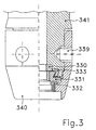
- Fig. 3 presents another connector designed to be used on a Sclaverand valve, which is not according to the ISO-standard. In such valve some of the threads are removed thereby forming two parallel secants on each side of the Sclaverand type valve.
- Such Sclaverand type valve can not tighten against the sealing means 330 of the above mentioned valve connectors, as the presurized air will try to escape through the secant openings.
- the bushing 340 is fastened to the housing 341 by means of detachable locking means 339, reaching into an external grove on the housing 341 perpendicular to the center axis.
- the internal sealing means 330 and the external sealing means 332 are arranged between the coupling bushing 331 and the housing 341 resp. the bushing 340.
- the coupling bushing 331 tightens against the undercut grove in the housing 341 assisted by another sealing means 333 fitting into the undercut grove.
- the coupling bushing When mounting the valve connector on the valve, the coupling bushing is running in the undercut grove in the valve housing, and if Sclaverand type valve can not tighten against the sealing means 330, the air will move into the space between the coupling bushing 331 and the other sealing means 333.
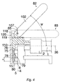
- the pump hose 1 is connected to the piston 76, which moves in the housing 110, by means of clamp ring 2.
- An elastic body 78 with sealing surfaces 79 (for the Dunlop-Woods and the Sclaverand valve) and 80 (for the Schrader valve) is compressed by the movable piston 76 by means of a lever 102, which is pressed down from the top position 82 to the position 83, where it is parallel with the centre line 36 of the ringclamp 2.
- the lever 102 turns around the axis 85 which is mounted in the housing 110 and to which the axis centre 107 is perpendicular and which intersects the centre line 4 of the opening 8 of the coupling hole 5.
- the sealing surface 79 lies at a distance 'a' from the opening 8 of the coupling hole 5, while the sealing surface 80 is adjacent to this.
- the area on the elastic means 78 bears against the piston 76.
- the piston air supply hole 75 has a diameter which is slightly smaller than the major diameter of the external thread 5V2, so that the Sclaverand valve has a natural stop at its connection. Thus the coupling place for the 5V2 thread is around the 5V2 thread.
- the lever 102 When disconnecting, the lever 102 is released. It now automatically turns back to the rest position 82, because the elastic body 78 returns to the unstressed condition. This is possible because the distance of the surface 118 from the axis centre 107 is larger than the distance of the surface 120 of the lever 102 at the top 119 of piston 76. The turn of the lever 102 stops when the plane surface 120 of the lever 102 stops against the flat top 119 of the piston. The top of the lever 102 is in rest position 82 under an angle ⁇ of approx. 45° with the centre line 36 of the ring damp 2.
- the housing 110 At the opening 8 of the coupling hole 5, the housing 110 is equipped with a cone 15 which facilitates the mounting of the universal connector.
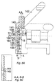
- Fig. 5A, 5B, 5C show the embodiment which is a combination of the connector of fig. 4 and the construction of an activating pin 142 which is shown in its top 18 position in Fig. 5A and in fig. 5B in its bottom 32 position.
- the pin 142 it is mounted on piston 138 by means of an edge 135 on the lower end of the cylinder 136.
- the construction of the pin becomes air-tight by means of a gasket seal 139 between the piston 138 and the cylinder 136.
- the turning knob 140 is equipped with a line 141 indicating the knob 140 position.
- the valve symbols 71, 72 correspond to the position 18 of the pin 142 and the symbol 73 corresponds to the position 32 of the pin 142 resp.
- the turning knob 140 is fixed at the valve symbols 71, 72, 73 when the piston fits in a recess 145 (fig. 5C) in the knob 140 with a bulb 144: see section A-A in fig. 5A and section B-B in fig. 5B, resp.
- the opening 8 of the coupling hole 5 has the centre line 4.
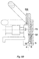
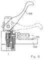
- Fig. 6 shows an universal connector in a special embodiment made for the purpose of being used in vehicle wheels with a narrow opening for the connector, where the connector is squeezed on the valve, and a Schrader valve is opened by means of the automatically moveable pin.
- the lever arm 319 has a special shape, and in the reaction arm 320 there is made a grove 321 for the pressure hose.
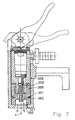
- Fig. 7 shows an universal connector in an embodiment, where the coupling is squeezed on the valve using a rubber bushing 366 with an incision 361 and a toroid ring 362 in the incision, and where a Schrader valve can be opened by means of an automatically movable activating pin, which is formed as a piston and is shown in the bottom position.
- the surface 367 can be slightly cone shaped.
- the incision 361 weaken the rubber bushing 366 at the place shown, which causes the rubber bushing to sqeeze the threads on the valve precisely where it is most convenient.
- torroid rings are arranged in the incisions, the force excerted on the valve threads are increased.
- Fig. 8 shows an universal connector in an embodiment like the one in fig. 7, but where the automatically movable pin is selfadjusting to production tolerances of the core of the Schrader valves.
Landscapes
- Engineering & Computer Science (AREA)
- General Engineering & Computer Science (AREA)
- Mechanical Engineering (AREA)
- Quick-Acting Or Multi-Walled Pipe Joints (AREA)
- Check Valves (AREA)
- Details Of Reciprocating Pumps (AREA)
- Compressors, Vaccum Pumps And Other Relevant Systems (AREA)
- Safety Valves (AREA)
- Valves And Accessory Devices For Braking Systems (AREA)
- Vehicle Cleaning, Maintenance, Repair, Refitting, And Outriggers (AREA)
- Details Of Valves (AREA)
- Pipe Accessories (AREA)
- Valve-Gear Or Valve Arrangements (AREA)
- Reciprocating Pumps (AREA)
Claims (12)
- Ventil-Anschlussstück für das Anschließen an Füllventile von Fahrzeugreifen, das aufweist:dadurch gekennzeichnet, dassein an eine Druckquelle angeschlossenes Gehäuse (3,16,19,35,77,110,134,151,164,190),im Gehäuse ein Ventil-Kupplungsloch (5) zum Kuppeln mit dem Füllventil, an welches das Ventil-Anschlussstück gekuppelt werden soll, wobei das Kupplungsloch eine Mittelachse (4) und eine äußere Mündung (8) aufweist, undim Kupplungsloch (5) eine Füllventil-Dichtungseinrichtung (12,13,79,80,200,194,330,332), koaxial mit der Mittelachse (4) des Kupplungslochs (5) angeordnet, zum Abdichten des Ventil-Anschlussstücks an Füllventilen unterschiedlichen Typs und/oder Größe,
das Ventil-Kupplungsloch (5) einen gestuften Aufbau aufweist, wodurch es mindestens zwei Ventilkupplungsloch-Abschnitte aufweist, die axial gegeneinander versetzt angeordnet sind und unterschiedliche Durchmesser haben und zum Aufnehmen von Füllventilen mit unterschiedlichem Durchmesser gestaltet sind, wobei der Lochabschnitt mit dem größeren Durchmesser näher an der äußeren Mündung (8) des Kupplungslochs liegt als der Lochabschnitt mit dem kleineren Durchmesser, und
die Füllventil-Dichtungseinheit einen ersten Ventil-Dichtungsabschnitt (13,80,194,332) und einen zweiten Ventil-Dichtungsabschnitt (12,79,200,330) aufweist, die entlang der Mittelachse (4) in unterschiedlichen Höhen angeordnet sind, wobei der erste Ventil-Dichtungsabschnitt am Lochabschnitt mit dem größeren Durchmesser angeordnet und ihm zugeordnet ist und wobei der zweite Ventil-Dichtungsabschnitt am Lochabschnitt mit dem kleineren Durchmesser angeordnet und ihm zugeordnet ist. - Ventil-Anschlussstück gemäß Anspruch 1, dadurch gekennzeichnet, dass der erste Dichtungsabschnitt (13,194,332) und der zweite Dichtungsabschnitt (12,200,330) gesonderte Teile sind.
- Ventil-Anschlussstück gemäß Anspruch 1, dadurch gekennzeichnet, dass jeder der Dichtungsabschnitte (13,194,332;12,200,330) am inneren Ende des jeweiligen Kupplungsloch-Abschnitts eine ringförmige Dichtfläche aufweist.
- Ventil-Anschlussstück gemäß Anspruch 1, dadurch gekennzeichnet, dass es im Kupplungsloch ein Sicherungsgewinde (7,9) zum Sichern des Ventil-Anschlussstücks auf dem Füllventil aufweist.
- Ventil-Anschlussstück gemäß Anspruch 4, dadurch gekennzeichnet, dass es eine Kupplungsbuchse (6,191,340) aufweist, die
um die Mittelachse (4) drehbar am Gehäuse (3,190,341) befestigt ist, und
gegenüber dem Gehäuse (3,190,341) mittels des zweiten Dichtungsabschnitts (12) abgedichtet ist,
wobei die Kupplungsbuchse das Sicherungsgewinde (7,9) und den ersten Dichtungsabschnitt (13,194,332) aufweist, und das Gehäuse (3,190,341) weist einen Anschlagrand (198) zum Stoppen der Kupplungsbewegung des Füllventils auf. - Ventil-Anschlussstück gemäß Anspruch 5, dadurch gekennzeichnet, dass die Kupplungsbuchse (191,340) eine äußere Buchse ist und eine innere Buchse (193,331) aufweist, die
nicht-drehbar mit der äußeren Buchse (191,340) mittels eines Satzes von Rippen (196) an der inneren Buchse (193,331) und zugeordneter Nuten (197) an der äußeren Buchse (191,340), die über den Buchsenumfang verteilt sind, gekuppelt ist, und
axial bewegbar in der äußeren Buchse (191,340) und im Gehäuse (190,341) angeordnet ist,
wobei der zweite Dichtungsabschnitt stufenförmig ist, eingebaut in eine zugehörige Einfräsung (201), so dass der Abschnitt des stufenförmigen zweiten Dichtungsabschnitts mit der höchsten Stufe der Mittellinie (4) am nächsten liegt. - Ventil-Anschlussstück gemäß Anspruch 6, dadurch gekennzeichnet, dass der zweite Dichtungsabschnitt ein erstes Teilstück (330) und ein zweites Teilstück (333) aufweist, von welchen das zweite Teilstück (333) in eine hinterschnittene Nut des Gehäuses (341) passt und zum Abdichten der inneren Buchse (331) gegen das Gehäuse angeordnet ist.
- Ventil-Anschlussstück gemäß Anspruch 1, dadurch gekennzeichnet, dass der erste Dichtungsabschnitt (80) und der zweite Dichtungsabschnitt (79) von einem elastischen Körper (78) gebildet werden, der als eine Buchse (78) aus deformierbarem Material gestaltet ist, um ein temporäres Sicherungsgewinde (79,80) zu bilden, wenn er radial gegen das Gewinde eines Füllventils gepresst wird, und dass ein Kolben (76) bewegbar im Gehäuse (110) angeordnet ist zum axialen Zusammenpressen des elastischen Körpers, wenn dieser mittels eines Hebels (102) betätigt wird, der aus einer Ruhestellung in eine Betätigungsstellung drehbar ist, in welcher der elastische Körper (78) zusammengepresst wird.
- Ventil-Anschlussstück gemäß Anspruch 8, gekennzeichnet durch ein Sperrmittel des Hebels, das in der Betätigungsstellung des Hebels mit einem Sperrmittel des Gehäuses zusammenwirkt.
- Ventil-Anschlussstück gemäß Anspruch 1, dadurch gekennzeichnet, dass das Gehäuse aus zwei Abschnitten mit einem vorbestimmten Winkel zwischen ihren jeweiligen Mittelachsen besteht, welcher 30° - 60° beträgt.
- Ventil-Anschlussstück gemäß Anspruch 9, dadurch gekennzeichnet, dass der Hebelarm (102) so eingerichtet ist, dass er, wenn er aus seiner Betätigungsstellung gelöst wird, angetrieben vom elastischen Körper (76) selbsttätig in die Ruhestellung zurückkehrt, wobei
der Hebel (102) zum Drehen um eine Achse (85) mit einem Zentrum (107) eingerichtet ist, das auf der Mittelachse (4) des Kupplungslochs (5) liegt,
der Abstand zwischen dem Zentrum (107) und einer Oberfläche (118) des Hebelarms (102), die in der Betätigungsstellung an der oberen Außenfläche (119) eines Kolbens (76) angreift, größer ist als der Abstand zwischen dem Zentrum (107) und einer Oberfläche (120) des Hebelarms (102), die in der Ruhestellung an der oberen Außenfläche des Kolbens (76) angreift. - Pumpe, durch Menschenkraft mittels Hand oder Fuß angetrieben, zum Aufblasen eines Fahrzeugreifens, dadurch gekennzeichnet, dass sie ein an ihr angeschlossenes Ventil-Anschlussstück gemäß einem der Ansprüche 1 - 11 aufweist.
Priority Applications (4)
| Application Number | Priority Date | Filing Date | Title |
|---|---|---|---|
| DE29624235U DE29624235U1 (de) | 1995-02-03 | 1996-02-02 | Ventilanschlußstück |
| EP20010121354 EP1170184B1 (de) | 1995-02-03 | 1996-02-02 | Pumpenkopf zur Verbindung mit einem Ventil |
| DK01121354T DK1170184T3 (da) | 1995-02-03 | 1996-02-02 | Ventilkonnektor |
| SI9630507T SI0807036T1 (en) | 1995-02-03 | 1996-02-02 | Valve connector |
Applications Claiming Priority (5)
| Application Number | Priority Date | Filing Date | Title |
|---|---|---|---|
| DK012595A DK171607B1 (da) | 1995-02-03 | 1995-02-03 | Ventilkobling |
| DK12595 | 1995-02-03 | ||
| GB9518558 | 1995-09-12 | ||
| GB9518558A GB2304844B (en) | 1995-09-12 | 1995-09-12 | Valve connector |
| PCT/DK1996/000055 WO1996010903A2 (en) | 1995-02-03 | 1996-02-02 | Valve connector |
Related Child Applications (2)
| Application Number | Title | Priority Date | Filing Date |
|---|---|---|---|
| EP20010121354 Division EP1170184B1 (de) | 1995-02-03 | 1996-02-02 | Pumpenkopf zur Verbindung mit einem Ventil |
| EP01121354.3 Division-Into | 2001-09-06 |
Publications (2)
| Publication Number | Publication Date |
|---|---|
| EP0807036A1 EP0807036A1 (de) | 1997-11-19 |
| EP0807036B1 true EP0807036B1 (de) | 2002-05-29 |
Family
ID=26063364
Family Applications (2)
| Application Number | Title | Priority Date | Filing Date |
|---|---|---|---|
| EP20010121354 Expired - Lifetime EP1170184B1 (de) | 1995-02-03 | 1996-02-02 | Pumpenkopf zur Verbindung mit einem Ventil |
| EP96901244A Expired - Lifetime EP0807036B1 (de) | 1995-02-03 | 1996-02-02 | Ventilverbindung |
Family Applications Before (1)
| Application Number | Title | Priority Date | Filing Date |
|---|---|---|---|
| EP20010121354 Expired - Lifetime EP1170184B1 (de) | 1995-02-03 | 1996-02-02 | Pumpenkopf zur Verbindung mit einem Ventil |
Country Status (26)
| Country | Link |
|---|---|
| US (5) | US6314985B1 (de) |
| EP (2) | EP1170184B1 (de) |
| JP (2) | JPH10512936A (de) |
| KR (3) | KR100443936B1 (de) |
| CN (4) | CN1143958C (de) |
| AP (1) | AP1017A (de) |
| AT (1) | ATE218109T1 (de) |
| BR (1) | BR9606991A (de) |
| CA (1) | CA2211997C (de) |
| CZ (1) | CZ225097A3 (de) |
| DE (1) | DE69621424T2 (de) |
| DK (2) | DK1170184T3 (de) |
| EA (1) | EA002218B1 (de) |
| ES (1) | ES2179173T3 (de) |
| FI (1) | FI973194A7 (de) |
| HU (1) | HUP9900497A3 (de) |
| MX (1) | MX9705850A (de) |
| NO (2) | NO316928B1 (de) |
| NZ (4) | NZ507410A (de) |
| OA (1) | OA10740A (de) |
| PL (1) | PL182707B1 (de) |
| PT (1) | PT807036E (de) |
| RO (1) | RO119138B1 (de) |
| SG (3) | SG97126A1 (de) |
| SK (1) | SK103997A3 (de) |
| WO (1) | WO1996010903A2 (de) |
Families Citing this family (50)
| Publication number | Priority date | Publication date | Assignee | Title |
|---|---|---|---|---|
| EP1170184B1 (de) | 1995-02-03 | 2012-12-05 | Nvb International A/S | Pumpenkopf zur Verbindung mit einem Ventil |
| TW363924B (en) * | 1996-05-14 | 1999-07-11 | Nvb Int | Activation pin for valve connector providing a reliable activation pin which is inexpensive, has low air-power resistance, and is therefore suitable for use as pump |
| DE19802601C2 (de) * | 1997-03-26 | 2000-11-02 | Scott Wu | Kopfstruktur für eine Luftpumpe |
| PL188865B1 (pl) * | 1997-11-19 | 2005-05-31 | Nvb Internat As | Urządzenie uruchamiające zawór |
| DE29923064U1 (de) | 1999-12-31 | 2000-02-24 | SKS Metaplast Scheffer-Klute GmbH, 59846 Sundern | Pumpenkopf zur Verbindung einer Handluftpumpe oder eines Luftschlauches o.dgl. mit einem Ventil eines Zweiradreifens |
| DE60234433D1 (de) | 2001-03-27 | 2009-12-31 | Nvb Composites Internat A S | Kombination aus einer kammer und einem kolben, pumpe, motor, stossdämpfer und wandler, die die kombination enthalten |
| US7195030B2 (en) * | 2002-04-19 | 2007-03-27 | Chiang-Pei Chen | Bicycle pump valve |
| US6978796B2 (en) * | 2002-09-25 | 2005-12-27 | Morris Ostrowiecki | Universal air valve connector |
| US7032612B2 (en) * | 2003-06-11 | 2006-04-25 | G.H. Meiser & Co | Dual use air chuck |
| US6843270B1 (en) * | 2003-12-22 | 2005-01-18 | Lo-Pin Wang | Connector of inflating device capable of coupling various types of valve stems |
| CN100386220C (zh) * | 2004-03-24 | 2008-05-07 | 青岛港(集团)有限公司 | 安全充气接头 |
| US7150416B2 (en) * | 2004-04-09 | 2006-12-19 | Tronox Llc | Liquid fuel injection |
| US7520538B2 (en) * | 2005-01-14 | 2009-04-21 | Mcgushion Kevin David | Orbital tube welding purge adaptor |
| US8122927B2 (en) * | 2005-10-19 | 2012-02-28 | Specialized Bicycle Components, Inc. | Inner-tube assembly for bicycle wheel |
| US8256447B2 (en) * | 2006-05-24 | 2012-09-04 | Opfinderfabrikken Aps | Pressure relief device for an inflatable tire |
| US7832773B2 (en) * | 2006-09-18 | 2010-11-16 | Krohn Kenneth P | Adjustable connector and method for its use |
| US20080190489A1 (en) * | 2007-02-13 | 2008-08-14 | Eqair, Llc | Chuck for tire inflation valve |
| US8109539B2 (en) | 2007-07-17 | 2012-02-07 | Krohn Kenneth P | Variable joining device and method for its use |
| CN101407160A (zh) * | 2007-10-12 | 2009-04-15 | 帕特里克·麦克尔·奥布莱恩 | 包含目视明显指示器的轮胎胎面及其制造方法 |
| US20090208271A1 (en) * | 2008-02-19 | 2009-08-20 | Krohn Kenneth P | Modular coupling system |
| US20090218808A1 (en) * | 2008-03-01 | 2009-09-03 | Krohn Kenneth P | Improved duct coupling system |
| US20090230678A1 (en) * | 2008-03-14 | 2009-09-17 | Krohn Kenneth P | Compression fitting adjustment system |
| DE102008053562A1 (de) * | 2008-07-23 | 2010-01-28 | Doukas Ag | Einrichtung zum Befüllen von Luftreifen mit einer Reifendichtflüssigkeit |
| US20100133810A1 (en) * | 2008-11-29 | 2010-06-03 | Krohn Kenneth P | Device for connecting to ducts of various sizes and shapes |
| US20100283237A1 (en) * | 2009-01-24 | 2010-11-11 | Krohn Kenneth P | Device for connecting to ducts of various sizes and shapes |
| TWI391588B (zh) * | 2009-12-08 | 2013-04-01 | Chang Hui Lin | 氣嘴接頭 |
| TW201207237A (en) * | 2010-08-03 | 2012-02-16 | Shu-Mu Wu | Air pump head |
| CN102529618B (zh) * | 2010-12-22 | 2014-09-03 | 林昌慧 | 气嘴接头 |
| TW201235565A (en) | 2011-02-25 | 2012-09-01 | Nvb Composites Internat Uk Ltd | Piston-chamber combination vanderblom motor |
| JP2014527601A (ja) | 2011-07-01 | 2014-10-16 | エヌブイビー コンポジッツ インターナショナル ユーケイ リミテッド | ピストン燃焼室組み合わせVanderblomモーター |
| TW201321635A (zh) * | 2011-11-30 | 2013-06-01 | Birzman Corp | 氣嘴接頭結構改良 |
| DE102012105914B4 (de) * | 2012-07-03 | 2015-08-27 | Beto Engineering and Marketing Co., Ltd. | Mehrzweck-Aufpumpanschluss |
| CN103574203B (zh) * | 2012-07-20 | 2016-02-03 | 双馀实业有限公司 | 多用途充气接头 |
| PL2955071T3 (pl) * | 2013-02-07 | 2018-04-30 | Chou | Urządzenie sprężarki powietrza do napełniania powietrzem oraz napełniania gumy |
| CN103375651B (zh) * | 2013-07-29 | 2015-08-12 | 无锡方盛换热器制造有限公司 | 打压充气装置用接头机构 |
| DE102013109402A1 (de) * | 2013-08-02 | 2015-02-05 | Ebm-Papst Landshut Gmbh | Radialgebläse mit kombinierter Dichtung und Schwingungsentkopplung |
| KR101436854B1 (ko) * | 2014-07-16 | 2014-09-02 | 주식회사 코베아 | 가스용기 접속 어댑터 |
| GB2601649B (en) * | 2015-08-26 | 2022-09-28 | Emulate Inc | Perfusion manifold assembly |
| CN106481915B (zh) * | 2015-08-27 | 2018-05-25 | 谢文正 | 脚踏车轮胎泵夹头 |
| WO2017155972A2 (en) | 2016-03-08 | 2017-09-14 | Fluid Handling Llc | Center bushing to balance axial forces in multi-stage pumps |
| CN106764151B (zh) * | 2016-11-24 | 2018-11-06 | 中国人民解放军空军勤务学院 | 一种防差错快速充气接头 |
| RU2656180C1 (ru) * | 2017-09-01 | 2018-05-31 | Акционерное общество "Научно-исследовательский и конструкторско-технологический институт подвижного состава" (АО "ВНИКТИ") | Запорный клапан для установки датчиков |
| IT201800002648A1 (it) | 2018-02-13 | 2019-08-13 | Nexion Spa | Metodo per gonfiare uno pneumatico |
| USD969876S1 (en) | 2020-12-11 | 2022-11-15 | Milwaukee Electric Tool Corporation | Inflator |
| CN113320338A (zh) * | 2021-07-05 | 2021-08-31 | 张杰平 | 一种新能源电动汽车后驱动轮 |
| CN113701906B (zh) * | 2021-08-26 | 2024-04-05 | 英业达科技有限公司 | 液冷回路中测量液体温度的方法 |
| RU209967U1 (ru) * | 2021-12-15 | 2022-03-24 | Общество с ограниченной ответственностью Управляющая компания "Алтайский завод прецизионных изделий" | Клапан сброса остаточного давления |
| US12013054B1 (en) | 2023-05-15 | 2024-06-18 | Radian Technologies Corporation | Chuck for airpump |
| US11850898B1 (en) | 2023-05-15 | 2023-12-26 | Radian Technologies Corporation | Chuck for airpump |
| DE102023115007A1 (de) | 2023-06-07 | 2024-12-12 | Scott Wu | Ventilverbinder für Aufblasvorrichtung |
Citations (3)
| Publication number | Priority date | Publication date | Assignee | Title |
|---|---|---|---|---|
| US4088147A (en) * | 1976-07-09 | 1978-05-09 | Control Devices, Incorported | Air chuck |
| US4165760A (en) * | 1977-10-17 | 1979-08-28 | Guenther Manfred H | Air chuck |
| GB1599304A (en) * | 1977-09-23 | 1981-09-30 | Scovill Inc | Inflation valve connectors |
Family Cites Families (47)
| Publication number | Priority date | Publication date | Assignee | Title |
|---|---|---|---|---|
| US1492838A (en) * | 1917-11-26 | 1924-05-06 | Lloyd W Dilweg | Device for transmitting compressed air to automob ile tires |
| US1383008A (en) * | 1920-04-13 | 1921-06-28 | Schroeder S Son Inc A | Double pump-coupling |
| US1789306A (en) * | 1924-01-28 | 1931-01-20 | Arno A Ewald | Tire-filling valve head |
| GB231992A (en) | 1924-02-29 | 1925-04-16 | Dunlop Rubber Co | An improved connection for fitment to valves of pneumatic tyres |
| GB292362A (en) * | 1927-07-05 | 1928-06-21 | Royce Stuart Boyce | Improvements in and relating to devices for connecting a pump or other source of pressure to pneumatic tyres and other objects for the purpose of inflating the same |
| US1784822A (en) * | 1928-02-15 | 1930-12-16 | Dill Mfg Co | Air chuck |
| US1850111A (en) | 1928-09-10 | 1932-03-22 | Paul C Swole | Combined air gauge and self closing outlet fitting |
| US2025067A (en) * | 1934-12-17 | 1935-12-24 | Thomas S Miller | Tank filling device |
| US2257498A (en) * | 1939-10-10 | 1941-09-30 | Clarence K Hansen | Tire inflation apparatus |
| US2489397A (en) | 1944-05-05 | 1949-11-29 | Brummer Henry | Tire valve operating device |
| US2716998A (en) * | 1949-03-02 | 1955-09-06 | Joseph J Knasko | Combined tire inflating chuck, deflator and blow gun |
| US2685906A (en) | 1952-01-19 | 1954-08-10 | Scovill Manufacturing Co | Running inflation and deflation system |
| GB872246A (en) | 1956-08-03 | 1961-07-05 | Walters & Dobson Ltd | Improvements in or relating to tyre valve connectors |
| GB920327A (en) * | 1958-08-19 | 1963-03-06 | Walters & Dobson Ltd | Improvements in or relating to tyre valve connectors |
| US2976906A (en) | 1958-09-10 | 1961-03-28 | Wunibald I E Kamm | Tire pressure control device |
| GB977139A (en) | 1962-10-15 | 1964-12-02 | Walters & Dobson Ltd | Improvements in or relating to tyre valve connectors |
| US3249144A (en) | 1964-09-23 | 1966-05-03 | Berg Mfg & Sales Co | Tire pressure system and valve |
| FR2180164A5 (de) * | 1972-04-11 | 1973-11-23 | Poutrait Morin | |
| DE2544555A1 (de) | 1975-10-04 | 1977-04-07 | Magirus Deutz Ag | Vorrichtung zur steuerung des luftdruckes im reifen eines fahrzeuges |
| US4489855A (en) | 1982-08-27 | 1984-12-25 | Code Manufacturing, Inc. | Instant tire inflator |
| AU575809B2 (en) | 1983-01-27 | 1988-08-11 | Precision Valve Corporation | Tire valve connector |
| FR2552851B1 (fr) * | 1983-09-30 | 1986-08-14 | Poutrait Morin | Embouts destines a etre fixes aux extremites d'un conduit flexible, pour constituer un raccord utilisable sur une pompe portative pour le gonflage de pneumatiques, et raccord comportant de tels embouts |
| DE8602739U1 (de) | 1986-02-03 | 1987-10-01 | Alligator Ventilfabrik GmbH, 7928 Giengen | Ventil für Luftreifen |
| US4662512A (en) * | 1986-03-07 | 1987-05-05 | Durand Jean Jacques | Unitary package for a glass or similar article |
| US4662412A (en) | 1986-05-13 | 1987-05-05 | Peter Bergmann | Inflating device for use single-handed |
| US4712812A (en) * | 1986-09-02 | 1987-12-15 | Weir Iii Joseph W | Universal fittings |
| DE3819771A1 (de) | 1987-12-18 | 1989-07-06 | Karl Scheffer Klute Gmbh & Co | Handluftpumpe fuer zweiradreifen |
| DE3819777A1 (de) * | 1988-06-10 | 1989-12-21 | Bayer Ag | Fuellstoffhaltige, polymerisierbare massen und deren verwendung |
| US4938272A (en) | 1989-01-26 | 1990-07-03 | General Motors Corporation | Valve actuator for tire pressure management |
| US4932451A (en) | 1989-01-26 | 1990-06-12 | General Motors Corporation | Vehicle wheel end assembly with air passage |
| FR2653523B3 (fr) | 1989-10-19 | 1991-10-04 | Hernandez Manuel | Raccord d'adaptation d'une bonbonne de gaz comprime a une valve de gonflage de pneu. |
| US5012954A (en) * | 1990-02-08 | 1991-05-07 | Will Conrad A | Tire inflation system |
| DE4120188C1 (de) | 1991-06-19 | 1992-09-17 | Cramer Gmbh & Co Kg, 5750 Menden, De | |
| US5094263A (en) | 1991-08-02 | 1992-03-10 | General Motors Corporation | Tire pressure management actuator with bypass leakage prevention |
| US5379796A (en) * | 1994-02-23 | 1995-01-10 | Wang; Lopin | Air pump head capable of engaging tire air valve in twist-locking manner |
| DK171607B1 (da) | 1995-02-03 | 1997-02-24 | Nvb International | Ventilkobling |
| EP1170184B1 (de) * | 1995-02-03 | 2012-12-05 | Nvb International A/S | Pumpenkopf zur Verbindung mit einem Ventil |
| US5645100A (en) | 1995-07-31 | 1997-07-08 | Chuang; Louis | Hand pump for engaging with different tire valves |
| TW400420B (en) | 1995-09-12 | 2000-08-01 | Nvb Int | Valve connector |
| US5778923A (en) | 1995-10-25 | 1998-07-14 | Marston; Philip William | Anti-seepage self-gauging inflation valve system |
| DE19601952A1 (de) | 1996-01-09 | 1997-07-10 | Gruener Uko Picasso | Luftdruckrohr-Flasche mit Ventil |
| TW390942B (en) * | 1996-04-22 | 2000-05-21 | Schwinn Cycling & Fitness Inc | Combination pump head |
| TW363924B (en) * | 1996-05-14 | 1999-07-11 | Nvb Int | Activation pin for valve connector providing a reliable activation pin which is inexpensive, has low air-power resistance, and is therefore suitable for use as pump |
| US5785076A (en) | 1996-05-20 | 1998-07-28 | You; Bae-Jou | Inflating assembly for tire |
| US5819781A (en) | 1997-07-28 | 1998-10-13 | Wu; Scott | Pumping device with a pivotal lever for various valves |
| PL188865B1 (pl) * | 1997-11-19 | 2005-05-31 | Nvb Internat As | Urządzenie uruchamiające zawór |
| US6648005B2 (en) * | 1998-11-13 | 2003-11-18 | Nvb International | Activation pin |
-
1996
- 1996-02-02 EP EP20010121354 patent/EP1170184B1/de not_active Expired - Lifetime
- 1996-02-02 PT PT96901244T patent/PT807036E/pt unknown
- 1996-02-02 NZ NZ50741096A patent/NZ507410A/xx unknown
- 1996-02-02 PL PL96321954A patent/PL182707B1/pl not_active IP Right Cessation
- 1996-02-02 NZ NZ335072A patent/NZ335072A/en unknown
- 1996-02-02 KR KR1019970705141A patent/KR100443936B1/ko not_active Expired - Fee Related
- 1996-02-02 HU HU9900497A patent/HUP9900497A3/hu active IP Right Revival
- 1996-02-02 SG SG9900059A patent/SG97126A1/en unknown
- 1996-02-02 MX MX9705850A patent/MX9705850A/es not_active IP Right Cessation
- 1996-02-02 DK DK01121354T patent/DK1170184T3/da active
- 1996-02-02 JP JP51227596A patent/JPH10512936A/ja not_active Ceased
- 1996-02-02 BR BR9606991A patent/BR9606991A/pt not_active IP Right Cessation
- 1996-02-02 AP APAP/P/1997/001061A patent/AP1017A/en active
- 1996-02-02 EP EP96901244A patent/EP0807036B1/de not_active Expired - Lifetime
- 1996-02-02 CZ CZ972250A patent/CZ225097A3/cs unknown
- 1996-02-02 DK DK96901244T patent/DK0807036T3/da active
- 1996-02-02 CA CA 2211997 patent/CA2211997C/en not_active Expired - Fee Related
- 1996-02-02 EA EA199700108A patent/EA002218B1/ru not_active IP Right Cessation
- 1996-02-02 KR KR10-2001-7001369A patent/KR100443938B1/ko not_active Expired - Fee Related
- 1996-02-02 AT AT96901244T patent/ATE218109T1/de not_active IP Right Cessation
- 1996-02-02 DE DE69621424T patent/DE69621424T2/de not_active Expired - Lifetime
- 1996-02-02 ES ES96901244T patent/ES2179173T3/es not_active Expired - Lifetime
- 1996-02-02 KR KR10-2001-7001368A patent/KR100443939B1/ko not_active Expired - Fee Related
- 1996-02-02 SG SG9900060A patent/SG90033A1/en unknown
- 1996-02-02 NZ NZ30056596A patent/NZ300565A/xx unknown
- 1996-02-02 RO RO97-01451A patent/RO119138B1/ro unknown
- 1996-02-02 SK SK1039-97A patent/SK103997A3/sk unknown
- 1996-02-02 WO PCT/DK1996/000055 patent/WO1996010903A2/en not_active Ceased
- 1996-02-02 NZ NZ33507096A patent/NZ335070A/xx unknown
- 1996-02-02 CN CNB961917741A patent/CN1143958C/zh not_active Expired - Fee Related
- 1996-02-02 SG SG9900058A patent/SG91809A1/en unknown
-
1997
- 1997-04-18 US US08/837,505 patent/US6314985B1/en not_active Expired - Fee Related
- 1997-07-04 NO NO19973112A patent/NO316928B1/no unknown
- 1997-08-01 OA OA70059A patent/OA10740A/en unknown
- 1997-08-01 FI FI973194A patent/FI973194A7/fi not_active IP Right Cessation
-
2001
- 2001-08-24 US US09/939,170 patent/US6631729B2/en not_active Expired - Fee Related
-
2002
- 2002-05-15 CN CNB021199310A patent/CN1212243C/zh not_active Expired - Fee Related
- 2002-05-15 CN CNB021199329A patent/CN1212244C/zh not_active Expired - Fee Related
- 2002-05-15 CN CNB021199337A patent/CN1212245C/zh not_active Expired - Fee Related
-
2003
- 2003-08-07 US US10/635,433 patent/US7273066B2/en not_active Expired - Fee Related
-
2004
- 2004-05-18 NO NO20042033A patent/NO20042033L/no not_active Application Discontinuation
- 2004-06-02 JP JP2004164437A patent/JP2005096741A/ja active Pending
-
2007
- 2007-08-17 US US11/840,793 patent/US20080173351A1/en not_active Abandoned
-
2009
- 2009-04-29 US US12/432,678 patent/US20090205718A1/en not_active Abandoned
Patent Citations (3)
| Publication number | Priority date | Publication date | Assignee | Title |
|---|---|---|---|---|
| US4088147A (en) * | 1976-07-09 | 1978-05-09 | Control Devices, Incorported | Air chuck |
| GB1599304A (en) * | 1977-09-23 | 1981-09-30 | Scovill Inc | Inflation valve connectors |
| US4165760A (en) * | 1977-10-17 | 1979-08-28 | Guenther Manfred H | Air chuck |
Also Published As
Similar Documents
| Publication | Publication Date | Title |
|---|---|---|
| EP0807036B1 (de) | Ventilverbindung | |
| US6035894A (en) | Coupling device for rapid connection | |
| US6651689B1 (en) | Valve stem assembly for a pneumatic tire | |
| AU760196B2 (en) | Valve connector | |
| PL186149B1 (pl) | Końcówka do nadmuchiwania opon pojazdów | |
| KR100443937B1 (ko) | 밸브 연결기 | |
| AU2003231658A1 (en) | Valve Connector | |
| AU4534496A (en) | Valve connector | |
| AU2004100420B4 (en) | A non-return valve | |
| US20250135809A1 (en) | Pneumatic valve, pump head and accessories for a pneumatic valve | |
| CN216922432U (zh) | 放气装置及打气筒 | |
| WO2024206787A1 (en) | A pneumatic valve having a unitary valve core with insert | |
| HK1051345A (en) | Valve connector | |
| HK1051344A (en) | Valve connector |
Legal Events
| Date | Code | Title | Description |
|---|---|---|---|
| PUAI | Public reference made under article 153(3) epc to a published international application that has entered the european phase |
Free format text: ORIGINAL CODE: 0009012 |
|
| 17P | Request for examination filed |
Effective date: 19970902 |
|
| AK | Designated contracting states |
Kind code of ref document: A1 Designated state(s): AT BE CH DE DK ES FR GB GR IE IT LI LU MC NL PT SE |
|
| AX | Request for extension of the european patent |
Free format text: AL PAYMENT 970902;LT PAYMENT 970902;LV PAYMENT 970902;SI PAYMENT 970902 |
|
| 17Q | First examination report despatched |
Effective date: 19980519 |
|
| GRAG | Despatch of communication of intention to grant |
Free format text: ORIGINAL CODE: EPIDOS AGRA |
|
| RAP1 | Party data changed (applicant data changed or rights of an application transferred) |
Owner name: NVB INTERNATIONAL A/S |
|
| GRAG | Despatch of communication of intention to grant |
Free format text: ORIGINAL CODE: EPIDOS AGRA |
|
| GRAH | Despatch of communication of intention to grant a patent |
Free format text: ORIGINAL CODE: EPIDOS IGRA |
|
| GRAH | Despatch of communication of intention to grant a patent |
Free format text: ORIGINAL CODE: EPIDOS IGRA |
|
| GRAA | (expected) grant |
Free format text: ORIGINAL CODE: 0009210 |
|
| AK | Designated contracting states |
Kind code of ref document: B1 Designated state(s): AT BE CH DE DK ES FR GB GR IE IT LI LU MC NL PT SE |
|
| AX | Request for extension of the european patent |
Free format text: AL PAYMENT 19970902;LT PAYMENT 19970902;LV PAYMENT 19970902;SI PAYMENT 19970902 |
|
| REF | Corresponds to: |
Ref document number: 218109 Country of ref document: AT Date of ref document: 20020615 Kind code of ref document: T |
|
| REG | Reference to a national code |
Ref country code: GB Ref legal event code: FG4D |
|
| REG | Reference to a national code |
Ref country code: CH Ref legal event code: EP |
|
| REG | Reference to a national code |
Ref country code: IE Ref legal event code: FG4D |
|
| REF | Corresponds to: |
Ref document number: 69621424 Country of ref document: DE Date of ref document: 20020704 |
|
| REG | Reference to a national code |
Ref country code: DK Ref legal event code: T3 |
|
| REG | Reference to a national code |
Ref country code: CH Ref legal event code: NV Representative=s name: PATENTANWAELTE SCHAAD, BALASS, MENZL & PARTNER AG |
|
| REG | Reference to a national code |
Ref country code: PT Ref legal event code: SC4A Free format text: AVAILABILITY OF NATIONAL TRANSLATION Effective date: 20020828 |
|
| REG | Reference to a national code |
Ref country code: GR Ref legal event code: EP Ref document number: 20020402725 Country of ref document: GR |
|
| ET | Fr: translation filed | ||
| REG | Reference to a national code |
Ref country code: ES Ref legal event code: FG2A Ref document number: 2179173 Country of ref document: ES Kind code of ref document: T3 |
|
| PGFP | Annual fee paid to national office [announced via postgrant information from national office to epo] |
Ref country code: GR Payment date: 20030226 Year of fee payment: 8 |
|
| PLBE | No opposition filed within time limit |
Free format text: ORIGINAL CODE: 0009261 |
|
| STAA | Information on the status of an ep patent application or granted ep patent |
Free format text: STATUS: NO OPPOSITION FILED WITHIN TIME LIMIT |
|
| 26N | No opposition filed |
Effective date: 20030303 |
|
| REG | Reference to a national code |
Ref country code: CH Ref legal event code: NV Representative=s name: WALDER WYSS & PARTNER |
|
| PG25 | Lapsed in a contracting state [announced via postgrant information from national office to epo] |
Ref country code: GR Free format text: LAPSE BECAUSE OF NON-PAYMENT OF DUE FEES Effective date: 20040903 |
|
| REG | Reference to a national code |
Ref country code: SI Ref legal event code: IF |
|
| REG | Reference to a national code |
Ref country code: CH Ref legal event code: PL |
|
| REG | Reference to a national code |
Ref country code: CH Ref legal event code: AEN Free format text: DAS PATENT IST AUFGRUND DES WEITERBEHANDLUNGSANTRAGS VOM 19.10.2005 REAKTIVIERT WORDEN. |
|
| PG25 | Lapsed in a contracting state [announced via postgrant information from national office to epo] |
Ref country code: AT Free format text: LAPSE BECAUSE OF NON-PAYMENT OF DUE FEES Effective date: 20060202 |
|
| PG25 | Lapsed in a contracting state [announced via postgrant information from national office to epo] |
Ref country code: LI Free format text: LAPSE BECAUSE OF NON-PAYMENT OF DUE FEES Effective date: 20060228 Ref country code: CH Free format text: LAPSE BECAUSE OF NON-PAYMENT OF DUE FEES Effective date: 20060228 |
|
| LTLA | Lt: lapse of european patent or patent extension |
Effective date: 20060202 |
|
| REG | Reference to a national code |
Ref country code: CH Ref legal event code: PL |
|
| REG | Reference to a national code |
Ref country code: SI Ref legal event code: KO00 Effective date: 20061011 |
|
| PG25 | Lapsed in a contracting state [announced via postgrant information from national office to epo] |
Ref country code: PT Free format text: LAPSE BECAUSE OF NON-PAYMENT OF DUE FEES Effective date: 20070802 |
|
| REG | Reference to a national code |
Ref country code: PT Ref legal event code: MM4A Free format text: LAPSE DUE TO NON-PAYMENT OF FEES Effective date: 20070802 |
|
| PGRI | Patent reinstated in contracting state [announced from national office to epo] |
Ref country code: AT Effective date: 20070906 |
|
| REG | Reference to a national code |
Ref country code: CH Ref legal event code: AEN Free format text: DAS PATENT IST AM 07.02.2008 GESTUETZT AUF DAS AM 27.02.2007 EINGEREICHTE WIEDEREINSETZUNGSGESUCH AUF GRUND VON ART. 47 PATG WIEDER IN KRAFT GESETZT W |
|
| PGRI | Patent reinstated in contracting state [announced from national office to epo] |
Ref country code: CH Effective date: 20080207 |
|
| PG25 | Lapsed in a contracting state [announced via postgrant information from national office to epo] |
Ref country code: LU Free format text: LAPSE BECAUSE OF NON-PAYMENT OF DUE FEES Effective date: 20080229 |
|
| PGRI | Patent reinstated in contracting state [announced from national office to epo] |
Ref country code: CH Effective date: 20080207 |
|
| PGFP | Annual fee paid to national office [announced via postgrant information from national office to epo] |
Ref country code: MC Payment date: 20090825 Year of fee payment: 14 Ref country code: IE Payment date: 20090825 Year of fee payment: 14 |
|
| PGFP | Annual fee paid to national office [announced via postgrant information from national office to epo] |
Ref country code: LU Payment date: 20090828 Year of fee payment: 14 Ref country code: GB Payment date: 20090825 Year of fee payment: 14 Ref country code: DE Payment date: 20090824 Year of fee payment: 14 |
|
| REG | Reference to a national code |
Ref country code: PT Ref legal event code: NF4A Free format text: RESTITUTIO IN INTEGRUM Effective date: 20091216 |
|
| PGFP | Annual fee paid to national office [announced via postgrant information from national office to epo] |
Ref country code: BE Payment date: 20090825 Year of fee payment: 14 |
|
| PGRI | Patent reinstated in contracting state [announced from national office to epo] |
Ref country code: PT Effective date: 20091216 |
|
| REG | Reference to a national code |
Ref country code: PT Ref legal event code: MM4A Free format text: LAPSE DUE TO NON-PAYMENT OF FEES Effective date: 20100802 |
|
| BERE | Be: lapsed |
Owner name: *NVB INTERNATIONAL A/S Effective date: 20100228 |
|
| REG | Reference to a national code |
Ref country code: CH Ref legal event code: PL |
|
| REG | Reference to a national code |
Ref country code: DK Ref legal event code: EBP |
|
| EUG | Se: european patent has lapsed | ||
| GBPC | Gb: european patent ceased through non-payment of renewal fee |
Effective date: 20100202 |
|
| PG25 | Lapsed in a contracting state [announced via postgrant information from national office to epo] |
Ref country code: MC Free format text: LAPSE BECAUSE OF NON-PAYMENT OF DUE FEES Effective date: 20100301 Ref country code: LI Free format text: LAPSE BECAUSE OF NON-PAYMENT OF DUE FEES Effective date: 20100228 Ref country code: CH Free format text: LAPSE BECAUSE OF NON-PAYMENT OF DUE FEES Effective date: 20100228 |
|
| REG | Reference to a national code |
Ref country code: FR Ref legal event code: ST Effective date: 20101029 |
|
| REG | Reference to a national code |
Ref country code: IE Ref legal event code: MM4A |
|
| PG25 | Lapsed in a contracting state [announced via postgrant information from national office to epo] |
Ref country code: AT Free format text: LAPSE BECAUSE OF NON-PAYMENT OF DUE FEES Effective date: 20100202 |
|
| REG | Reference to a national code |
Ref country code: CH Ref legal event code: AEN Free format text: DAS PATENT IST AUFGRUND DES WEITERBEHANDLUNGSANTRAGS VOM 26.11.2010 REAKTIVIERT WORDEN. |
|
| REG | Reference to a national code |
Ref country code: FR Ref legal event code: RN |
|
| REG | Reference to a national code |
Ref country code: FR Ref legal event code: FC |
|
| PG25 | Lapsed in a contracting state [announced via postgrant information from national office to epo] |
Ref country code: PT Free format text: LAPSE BECAUSE OF NON-PAYMENT OF DUE FEES Effective date: 20100802 Ref country code: IE Free format text: LAPSE BECAUSE OF NON-PAYMENT OF DUE FEES Effective date: 20100202 Ref country code: FR Free format text: LAPSE BECAUSE OF NON-PAYMENT OF DUE FEES Effective date: 20100301 Ref country code: DK Free format text: LAPSE BECAUSE OF NON-PAYMENT OF DUE FEES Effective date: 20100228 |
|
| PGRI | Patent reinstated in contracting state [announced from national office to epo] |
Ref country code: CH Effective date: 20101126 |
|
| REG | Reference to a national code |
Ref country code: PT Ref legal event code: NF4A Free format text: RESTITUTIO IN INTEGRUM Effective date: 20110204 |
|
| PG25 | Lapsed in a contracting state [announced via postgrant information from national office to epo] |
Ref country code: DE Free format text: LAPSE BECAUSE OF NON-PAYMENT OF DUE FEES Effective date: 20100901 Ref country code: BE Free format text: LAPSE BECAUSE OF NON-PAYMENT OF DUE FEES Effective date: 20100228 |
|
| REG | Reference to a national code |
Ref country code: ES Ref legal event code: FD2A Effective date: 20110310 |
|
| PG25 | Lapsed in a contracting state [announced via postgrant information from national office to epo] |
Ref country code: IT Free format text: LAPSE BECAUSE OF NON-PAYMENT OF DUE FEES Effective date: 20100202 Ref country code: GB Free format text: LAPSE BECAUSE OF NON-PAYMENT OF DUE FEES Effective date: 20100202 |
|
| REG | Reference to a national code |
Ref country code: DK Ref legal event code: EGE |
|
| PGFP | Annual fee paid to national office [announced via postgrant information from national office to epo] |
Ref country code: PT Payment date: 20110131 Year of fee payment: 15 |
|
| PGRI | Patent reinstated in contracting state [announced from national office to epo] |
Ref country code: PT Effective date: 20110204 |
|
| PG25 | Lapsed in a contracting state [announced via postgrant information from national office to epo] |
Ref country code: ES Free format text: LAPSE BECAUSE OF NON-PAYMENT OF DUE FEES Effective date: 20110309 |
|
| PGRI | Patent reinstated in contracting state [announced from national office to epo] |
Ref country code: IT Effective date: 20110616 |
|
| PGFP | Annual fee paid to national office [announced via postgrant information from national office to epo] |
Ref country code: DK Payment date: 20110609 Year of fee payment: 16 |
|
| REG | Reference to a national code |
Ref country code: DE Ref legal event code: R073 Ref document number: 69621424 Country of ref document: DE |
|
| REG | Reference to a national code |
Ref country code: DE Ref legal event code: R082 Ref document number: 69621424 Country of ref document: DE Ref country code: DE Ref legal event code: R074 Ref document number: 69621424 Country of ref document: DE |
|
| REG | Reference to a national code |
Ref country code: DE Ref legal event code: R097 Ref document number: 69621424 Country of ref document: DE |
|
| REG | Reference to a national code |
Ref country code: NL Ref legal event code: V1 Effective date: 20110901 |
|
| PG25 | Lapsed in a contracting state [announced via postgrant information from national office to epo] |
Ref country code: ES Free format text: LAPSE BECAUSE OF NON-PAYMENT OF DUE FEES Effective date: 20100203 |
|
| REG | Reference to a national code |
Ref country code: CH Ref legal event code: PL |
|
| REG | Reference to a national code |
Ref country code: DE Ref legal event code: R074 Ref document number: 69621424 Country of ref document: DE Effective date: 20110910 |
|
| PG25 | Lapsed in a contracting state [announced via postgrant information from national office to epo] |
Ref country code: PT Free format text: LAPSE BECAUSE OF NON-PAYMENT OF DUE FEES Effective date: 20110802 Ref country code: LI Free format text: LAPSE BECAUSE OF NON-PAYMENT OF DUE FEES Effective date: 20110228 Ref country code: CH Free format text: LAPSE BECAUSE OF NON-PAYMENT OF DUE FEES Effective date: 20110228 |
|
| REG | Reference to a national code |
Ref country code: GB Ref legal event code: S28 Free format text: APPLICATION FILED |
|
| REG | Reference to a national code |
Ref country code: NL Ref legal event code: RD1H Effective date: 20111031 |
|
| REG | Reference to a national code |
Ref country code: FR Ref legal event code: ST Effective date: 20111102 |
|
| REG | Reference to a national code |
Ref country code: CH Ref legal event code: AEN Free format text: DAS PATENT IST AUFGRUND DES WEITERBEHANDLUNGSANTRAGS VOM 01.12.2011 REAKTIVIERT WORDEN. |
|
| PG25 | Lapsed in a contracting state [announced via postgrant information from national office to epo] |
Ref country code: NL Free format text: LAPSE BECAUSE OF NON-PAYMENT OF DUE FEES Effective date: 20110901 |
|
| PGFP | Annual fee paid to national office [announced via postgrant information from national office to epo] |
Ref country code: CH Payment date: 20111201 Year of fee payment: 16 |
|
| PGRI | Patent reinstated in contracting state [announced from national office to epo] |
Ref country code: CH Effective date: 20111202 |
|
| REG | Reference to a national code |
Ref country code: NL Ref legal event code: RD2H Effective date: 20120201 |
|
| REG | Reference to a national code |
Ref country code: DE Ref legal event code: R119 Ref document number: 69621424 Country of ref document: DE |
|
| REG | Reference to a national code |
Ref country code: ES Ref legal event code: NF2A Effective date: 20120621 |
|
| PGFP | Annual fee paid to national office [announced via postgrant information from national office to epo] |
Ref country code: NL Payment date: 20120229 Year of fee payment: 17 |
|
| PGRI | Patent reinstated in contracting state [announced from national office to epo] |
Ref country code: ES Effective date: 20120621 |
|
| REG | Reference to a national code |
Ref country code: GB Ref legal event code: S28 Free format text: APPLICATION WITHDRAWN Effective date: 20120815 |
|
| REG | Reference to a national code |
Ref country code: FR Ref legal event code: RN Effective date: 20120806 |
|
| REG | Reference to a national code |
Ref country code: FR Ref legal event code: FC Effective date: 20120813 |
|
| PG25 | Lapsed in a contracting state [announced via postgrant information from national office to epo] |
Ref country code: LU Free format text: LAPSE BECAUSE OF NON-PAYMENT OF DUE FEES Effective date: 20100202 Ref country code: SE Free format text: LAPSE BECAUSE OF NON-PAYMENT OF DUE FEES Effective date: 20100203 |
|
| PGFP | Annual fee paid to national office [announced via postgrant information from national office to epo] |
Ref country code: SE Payment date: 20120828 Year of fee payment: 17 |
|
| PGFP | Annual fee paid to national office [announced via postgrant information from national office to epo] |
Ref country code: IT Payment date: 20120829 Year of fee payment: 17 |
|
| PGRI | Patent reinstated in contracting state [announced from national office to epo] |
Ref country code: FR Effective date: 20121227 |
|
| PGFP | Annual fee paid to national office [announced via postgrant information from national office to epo] |
Ref country code: AT Payment date: 20120827 Year of fee payment: 17 Ref country code: FR Payment date: 20121227 Year of fee payment: 17 |
|
| PGFP | Annual fee paid to national office [announced via postgrant information from national office to epo] |
Ref country code: ES Payment date: 20130228 Year of fee payment: 18 |
|
| PG25 | Lapsed in a contracting state [announced via postgrant information from national office to epo] |
Ref country code: DE Free format text: LAPSE BECAUSE OF NON-PAYMENT OF DUE FEES Effective date: 20120503 |
|
| REG | Reference to a national code |
Ref country code: NL Ref legal event code: V1 Effective date: 20130901 |
|
| REG | Reference to a national code |
Ref country code: DK Ref legal event code: EBP |
|
| REG | Reference to a national code |
Ref country code: CH Ref legal event code: PL |
|
| REG | Reference to a national code |
Ref country code: AT Ref legal event code: MM01 Ref document number: 218109 Country of ref document: AT Kind code of ref document: T Effective date: 20130228 |
|
| PG25 | Lapsed in a contracting state [announced via postgrant information from national office to epo] |
Ref country code: NL Free format text: LAPSE BECAUSE OF NON-PAYMENT OF DUE FEES Effective date: 20130901 Ref country code: CH Free format text: LAPSE BECAUSE OF NON-PAYMENT OF DUE FEES Effective date: 20130228 Ref country code: LI Free format text: LAPSE BECAUSE OF NON-PAYMENT OF DUE FEES Effective date: 20130228 Ref country code: AT Free format text: LAPSE BECAUSE OF NON-PAYMENT OF DUE FEES Effective date: 20130228 |
|
| REG | Reference to a national code |
Ref country code: FR Ref legal event code: ST Effective date: 20131031 |
|
| PG25 | Lapsed in a contracting state [announced via postgrant information from national office to epo] |
Ref country code: IT Free format text: LAPSE BECAUSE OF NON-PAYMENT OF DUE FEES Effective date: 20130202 |
|
| PG25 | Lapsed in a contracting state [announced via postgrant information from national office to epo] |
Ref country code: DK Free format text: LAPSE BECAUSE OF NON-PAYMENT OF DUE FEES Effective date: 20130228 Ref country code: FR Free format text: LAPSE BECAUSE OF NON-PAYMENT OF DUE FEES Effective date: 20130228 |
|
| REG | Reference to a national code |
Ref country code: ES Ref legal event code: FD2A Effective date: 20150327 |
|
| PG25 | Lapsed in a contracting state [announced via postgrant information from national office to epo] |
Ref country code: ES Free format text: LAPSE BECAUSE OF NON-PAYMENT OF DUE FEES Effective date: 20140203 |