US5379796A - Air pump head capable of engaging tire air valve in twist-locking manner - Google Patents
Air pump head capable of engaging tire air valve in twist-locking manner Download PDFInfo
- Publication number
- US5379796A US5379796A US08/200,726 US20072694A US5379796A US 5379796 A US5379796 A US 5379796A US 20072694 A US20072694 A US 20072694A US 5379796 A US5379796 A US 5379796A
- Authority
- US
- United States
- Prior art keywords
- receiving space
- rotating member
- elastic body
- air pump
- air
- Prior art date
- Legal status (The legal status is an assumption and is not a legal conclusion. Google has not performed a legal analysis and makes no representation as to the accuracy of the status listed.)
- Expired - Fee Related
Links
- 238000010276 construction Methods 0.000 claims description 6
- 230000001154 acute effect Effects 0.000 claims 1
- 238000007789 sealing Methods 0.000 claims 1
- 238000005086 pumping Methods 0.000 description 3
- 239000000428 dust Substances 0.000 description 2
- 230000000717 retained effect Effects 0.000 description 1
Images


Classifications
-
- B—PERFORMING OPERATIONS; TRANSPORTING
- B60—VEHICLES IN GENERAL
- B60S—SERVICING, CLEANING, REPAIRING, SUPPORTING, LIFTING, OR MANOEUVRING OF VEHICLES, NOT OTHERWISE PROVIDED FOR
- B60S5/00—Servicing, maintaining, repairing, or refitting of vehicles
- B60S5/04—Supplying air for tyre inflation
-
- F—MECHANICAL ENGINEERING; LIGHTING; HEATING; WEAPONS; BLASTING
- F04—POSITIVE - DISPLACEMENT MACHINES FOR LIQUIDS; PUMPS FOR LIQUIDS OR ELASTIC FLUIDS
- F04B—POSITIVE-DISPLACEMENT MACHINES FOR LIQUIDS; PUMPS
- F04B33/00—Pumps actuated by muscle power, e.g. for inflating
- F04B33/005—Pumps actuated by muscle power, e.g. for inflating specially adapted for inflating tyres of non-motorised vehicles, e.g. cycles, tricycles
-
- Y—GENERAL TAGGING OF NEW TECHNOLOGICAL DEVELOPMENTS; GENERAL TAGGING OF CROSS-SECTIONAL TECHNOLOGIES SPANNING OVER SEVERAL SECTIONS OF THE IPC; TECHNICAL SUBJECTS COVERED BY FORMER USPC CROSS-REFERENCE ART COLLECTIONS [XRACs] AND DIGESTS
- Y10—TECHNICAL SUBJECTS COVERED BY FORMER USPC
- Y10T—TECHNICAL SUBJECTS COVERED BY FORMER US CLASSIFICATION
- Y10T137/00—Fluid handling
- Y10T137/3584—Inflatable article [e.g., tire filling chuck and/or stem]
- Y10T137/3724—With coupling means
Definitions
- the present invention relates generally to an air pump, and more particularly to an air pump head capable of engaging a tire air valve in a twist-locking manner.
- a bicycle air pump head of the prior art comprises a cylindrical body 51 having a neck 511 for connecting with a tubular member (not shown in the drawing) and a receiving space 512 of cylindrical construction, a pressing member 52 pivoted to the upper portion of the cylindrical body 51 by a pivoting pin 521 and provided with two pressing surfaces 522 and 523.
- the vertical distance S1 between the pressing surface 522 and the pivoting pin 521 is smaller than the vertical distance S2 between the pressing surface 523 and the pivoting pin 521.
- the air pump head further comprises a support member 53, a leakproof ring 54, an urging member 55, an elastic body 56, and an end jacket 57.
- the support member 53 is received in the receiving space 512 and under the pressing member 52 and provided in the lower side thereof with a cut 531.
- the leakproof ring 54 is fitted over the support member 53 for preventing the air from leaking from the upper portion of the cylindrical body 51.
- the urging member 55 is disposed under the support member 53 and provided with a through hole 551 in communication with the neck 511 and with a protruded column 552 for use in moving away the closing valve (not shown in the drawing) of the tire air valve.
- the elastic body 56 is disposed under the urging member 55.
- the end jacket 57 is fastened to the bottom of the cylindrical body 51 for locking the support member 53, the urging member 55 and the elastic body 56 in the receiving space 512 of the cylindrical body 51.
- the center slot 561 of the elastic body 56 is caused to engage a tire air valve before the pressing member 52 is moved upwards, as shown in FIG. 14, with the pressing surface 523 exerting a pressure on the support member 53.
- the distance S2 between the pressing surface 523 and the pivoting pin 521 becomes longer, thereby resulting in the support member 53 to cause the urging member 55 to move downwards a distance equal to S2-S1, so as to exert a pressure on the elastic body 56.
- the elastic body 56 is caused to deform, the inner diameter of the center slot 561 becomes narrower. The center slot 561 of the elastic body 56 is therefore caused to hold securely the tire air valve to facilitate the air pumping.
- the pressing member 52 must be pressed and turned to cause the elastic body 56 to engage the tire air valve. Such an action can hamper the pumping action.
- the end jacket 57 is often provided with a dust-protecting cover. However, the dust can be still caused to enter the pump head through the lower portion of the pressing member 52.
- an air pump head which comprises a housing, a rotating member, a locating member, two leakproof rings, an elastic body, an opening member, a pressing member, an end jacket, and a dust-proof jacket.
- the housing is provided therein with a first receiving space and a second receiving space.
- the rotating member is received in the first receiving space such that one end of the rotating member is fastened with the cylinder of the air pump.
- the body of the rotating member has a cam section corresponding in location to the second receiving space and further has centrally an air duct in communication with the cam section and the fastening end of the rotating member.
- Two leakproof elements are attached to both ends of the rotating member so as to seal off the first receiving space.
- the elastic body is disposed in the second receiving space for engaging a tire air valve.
- the opening member and the pressing member are disposed in the second receiving space such that the opening member is connected with the elastic body and that the pressing member and the opening member are lapped together.
- the end jacket is attached to the outer end of the second receiving space to ensure that the elastic body, the opening member and the pressing member are held securely in the second receiving space.
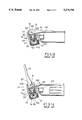
- FIG. 1 is a front elevational view of a first preferred embodiment of the present invention, which is not caused to engage a tire air valve.
- FIG. 2 is a sectional view of a portion taken along the line 2--2 as shown in FIG. 1.
- FIG. 3 is a sectional view of a portion taken along the line 3--3 as shown in FIG. 2.
- FIG. 4 is similar to FIG. 1, except that the first preferred embodiment has been rotated an angle of 90 degrees to be in an engaging state.
- FIG. 5 is a sectional view of a portion taken along the line 5--5 as shown in FIG. 4.
- FIG. 6 is a sectional view of a portion taken along the line 6--6 as shown in FIG. 5.
- FIG. 7 is a schematic view of a second preferred embodiment of the present invention, which is not in an engaging state.
- FIG. 8 is similar to FIG. 7, except that the second preferred embodiment of the present invention is in an engaging state.
- FIG. 9 is a schematic view of a third preferred embodiment of the present invention, which is not in an engaging state.
- FIG. 10 is sectional view of a portion taken along the line 10--10 as shown in FIG. 9.
- FIG. 11 is similar to FIG. 9, except that the third preferred embodiment is in an engaging state.
- FIG. 12 is a sectional view taken along the line 12--12 as shown in FIG, 11.
- FIG. 13 is a schematic view of an air pump head of the prior art, which is not in an engaging state.
- FIG. 14 is similar to FIG. 13, except that the air pump head is in an engaging state.
- an air pump head 20 of the present invention is shown to comprise the component parts described hereinafter.
- a housing 21 is provided therein centrally with a first receiving space 211 of columnar shape.
- the first and the second receiving spaces 211 and 212 are in communication with each other.
- the second receiving space 212 is provided in the outer wall of the open end thereof with a male screw portion 213.
- the housing 21 is provided in one end thereof with a recess 214 having an end wall 215 provided centrally with a through hole 216 in communication with the first receiving space 211.
- a rotating member 22 of a cylindrical shape is disposed in the first receiving space 211 and has one end 221 extending to the outside of the housing 21 to couple with the cylindrical body 19 of the air pump in such a manner that the end 221 can rotate with the cylindrical body 19.
- the rotating member 22 is provided with a cam section 222 corresponding in location to the second receiving space 212.
- the rotating member 22 is further provided therein with an air duct 223 having one end that is connected with the connecting end 221 of the cylindrical body 19 and having another end that is connected with the end surface 224 of the cam section 222.
- a locating member 23 has a head portion 231 having a threaded rod 232 extending from the center of one side thereof.
- the locating member 23 is fastened with another end 225 of the rotating member 22 by the threaded rod 232.
- the head portion 231 is disposed in the recess 214 such that the head portion 231 is retained by the end wall 215 of the recess 1214 so as to retain securely the rotating member 22 in the housing 21.
- Two leakproof rings 24 are disposed respectively in the outer sides of both ends of the rotating member 22 and are received in the first receiving space 211. These two leakproof rings 24 are located respectively in both sides of the second receiving space 212 to seal off the first receiving space 211.
- An elastic body 25 is disposed in the second receiving space 212 and provided with a tubular body 251 having an open end and another end provided with an end wall 252 which in turn is provided centrally with a round hole 253.
- An opening member 26 is disposed in the second receiving space 212 and provided with a protruded column 261 adjacent to one end of the elastic body 25 for pushing to open the closing valve (not shown in the drawing) of the tire air valve.
- the opening member 26 is provided with a predetermined number of through holes 262 for keeping the air in the second receiving space 212 to flow freely.
- a pressing member 27 is disposed in the second receiving space 212 and has one end adjacent to the opening member 26 and another end that is lapped with the cam section 222 of the rotating member 22.
- the pressing member 27 is provided with a predetermined number of through holes 271 for keeping the air in the second receiving space 212 to flow freely.
- a pressing member 27 is disposed in the second receiving space 212 and has one end adjacent to the opening member 26 and another end that is lapped with the cam section 222 of the rotating member 22.
- the pressing member 27 is provide with a predetermined number of through holes 271 for keeping the air in the second receiving space 212 to flow freely.
- An end jacket 28 of a ring-shaped construction is provided therein with female threads engageable with the threaded portion 213 of the housing 21 for preventing the elastic body 25, the opening member 26 and the pressing member 27 from slipping out of the second receiving space 212.
- a dustproof jacket 29 is fitted over the locating member 23 and disposed in the recess 214 of the housing for preventing the dust from entering the housing 21.
- the cylindrical body 19 is turned for a 90-degree angle to cause the lapping position of the pressing member 27 and the rotating member 22 to move from the end surface 224 of the cam section 222 to an arcuate surface 224', thereby causing the cam section 222 to exert a pressure on the pressing member 27, which is then caused to move a predetermined distance along the axis of the second receiving space 212 toward the elastic body 25.
- the elastic body 25 is forced to deform so as to cause the inner diameter of the tubular body 251 of the elastic body 25 to become smaller to enable the elastic body 25 to engage securely the air valve of a tire.
- the second embodiment of the present invention is similar in construction to the first preferred embodiment described above, with the difference being that the former has a housing 31 provided with a first receiving space 311 and a second receiving space 312 having a center line forming a predetermined bevel angle with a center line of the first receiving space 311.
- the angle referred to above is about 12 degrees. Therefore, the pressing member 37 of the second preferred embodiment is wedge-shaped so as to enable one end of the pressing member 37 to lap with the opening member 36 and to enable another end of the pressing member 37 to lap with the cam section 322 of the rotating member 32.
- the pressing member 37 is enabled to move along the axis of the second receiving space 312 at the time when the rotating member 32 is twisted to turn, as illustrated in FIG. 8.
- the pump head 30 of the second preferred embodiment described above has an angle of inclination to facilitate the pumping operation.
- rotation angle of the rotating member of the present invention may be other than 90 degrees, either greater or smaller than 90 degrees, and that the shape of the cam section of the present invention may be embodied in other specific forms.
- the third preferred embodiment of the present invention is similar in construction to the second preferred embodiment, with the difference being that the former has a rotating member 42 provided with a columnar cam section 422 of a smaller outer diameter and that the cam section 422 is disposed eccentrically.
- the pressing member 47 has an arcuate end that is lapped with the cam section 422.
- the pressing member 47 may be made up of two elements which are of a ring-shaped or wedge-shaped and which may be made integrally.
- the rotation angle of the rotating member 42 of the third preferred embodiment described above is 180 degrees.
- the present invention may be provided with a cover that is fitted over the end jacket to seal off the open end of the end jacket.
- the cylindrical body 19 of the present invention is provided with a pressure device 18. There is an indicator marked on a place located between the housing and the cylindrical body to display the engaging position of the air pump head.
Landscapes
- Engineering & Computer Science (AREA)
- Mechanical Engineering (AREA)
- General Engineering & Computer Science (AREA)
- Compressor (AREA)
- Check Valves (AREA)
Abstract
Description
Claims (5)
Priority Applications (1)
| Application Number | Priority Date | Filing Date | Title |
|---|---|---|---|
| US08/200,726 US5379796A (en) | 1994-02-23 | 1994-02-23 | Air pump head capable of engaging tire air valve in twist-locking manner |
Applications Claiming Priority (1)
| Application Number | Priority Date | Filing Date | Title |
|---|---|---|---|
| US08/200,726 US5379796A (en) | 1994-02-23 | 1994-02-23 | Air pump head capable of engaging tire air valve in twist-locking manner |
Publications (1)
| Publication Number | Publication Date |
|---|---|
| US5379796A true US5379796A (en) | 1995-01-10 |
Family
ID=22742934
Family Applications (1)
| Application Number | Title | Priority Date | Filing Date |
|---|---|---|---|
| US08/200,726 Expired - Fee Related US5379796A (en) | 1994-02-23 | 1994-02-23 | Air pump head capable of engaging tire air valve in twist-locking manner |
Country Status (1)
| Country | Link |
|---|---|
| US (1) | US5379796A (en) |
Cited By (26)
| Publication number | Priority date | Publication date | Assignee | Title |
|---|---|---|---|---|
| US5749392A (en) * | 1995-11-28 | 1998-05-12 | Zefal | Pump connector device |
| US5762095A (en) * | 1996-04-22 | 1998-06-09 | Schwinn Cycling & Fitness Inc. | Combination pump head |
| US5819781A (en) * | 1997-07-28 | 1998-10-13 | Wu; Scott | Pumping device with a pivotal lever for various valves |
| US5921269A (en) * | 1997-06-30 | 1999-07-13 | Wu; Scott | Tire inflator |
| US5975109A (en) * | 1998-07-24 | 1999-11-02 | Wu; Scott | Retaining pin pumper devices of the type having a pivotal lever for various valves |
| WO2000011384A1 (en) * | 1998-08-18 | 2000-03-02 | Bell Sports, Inc. | Air pump valve head for both schrader and presta valves |
| US6073645A (en) * | 1999-03-25 | 2000-06-13 | Wu; Scott | Pumping device with an internal pivotal tube for various valves |
| US6076544A (en) * | 1999-08-18 | 2000-06-20 | Bell Sports, Inc. | Air pump valve head for both schrader and presta valves |
| US6102063A (en) * | 1998-08-18 | 2000-08-15 | Bell Sports, Inc. | Air pump valve head for gripping both schrader and presta valves |
| US6146116A (en) * | 1997-10-21 | 2000-11-14 | Wu; Scott | Pumping device with a pivotal lever for various valves |
| US6220273B1 (en) * | 1999-03-25 | 2001-04-24 | Scott Wu | Pumping device with an internal pivotal tube for various valves |
| US6289920B1 (en) * | 2000-04-24 | 2001-09-18 | Lo-Pin Wang | Air pump nozzle capable of adjusting automatically to fit inflation valves of various types |
| SG90033A1 (en) * | 1995-02-03 | 2002-07-23 | Nvb Internat Of Gaerdet | Valve connector |
| US20060081291A1 (en) * | 2004-09-09 | 2006-04-20 | Cube Investments Limited | Central vacuum cleaner wall valve, hose nipple, and cleaning system |
| US20070079469A1 (en) * | 2005-10-07 | 2007-04-12 | Cube Investments Limited | Integrated central vacuum cleaner suction device and control |
| US20070079466A1 (en) * | 2005-10-07 | 2007-04-12 | Cube Investments Limited | Central vacuum cleaner multiple vacuum source control |
| US20070154063A1 (en) * | 1995-06-07 | 2007-07-05 | Automotive Technologies International, Inc. | Image Processing Using Rear View Mirror-Mounted Imaging Device |
| US20080222836A1 (en) * | 2004-05-12 | 2008-09-18 | Cube Investments Limited | Central vacuum cleaning system control subsytems |
| US7958594B2 (en) | 2005-10-07 | 2011-06-14 | Cube Investments Limited | Central vacuum cleaner cross-controls |
| US8096014B2 (en) | 2005-10-07 | 2012-01-17 | Cube Investments Limited | Central vacuum cleaner control, unit and system with contaminant sensor |
| US8516653B2 (en) | 2004-09-17 | 2013-08-27 | Cube Investments Limited | Cleaner handle and cleaner handle housing sections |
| DE202016100221U1 (en) | 2015-12-25 | 2016-04-20 | Beto Engineering and Marketing Co., Ltd. | Air pump with the ability of a twist-lock engagement |
| US20170056895A1 (en) * | 2015-08-28 | 2017-03-02 | Beto Engineering and Marketing Co., Ltd. | Resiliently flexible nozzle head for inflator |
| US9649898B2 (en) * | 2015-05-27 | 2017-05-16 | Motion Pro, Inc. | Air chuck with variable angle swivel head |
| USD800787S1 (en) * | 2015-08-27 | 2017-10-24 | Ride Air Innovations Ltd. | Air pump |
| US9945503B2 (en) * | 2016-08-09 | 2018-04-17 | Beto Engineering and Marketing Co., Ltd. | Rotate-to-press inflation adaptor for English valves |
Citations (9)
| Publication number | Priority date | Publication date | Assignee | Title |
|---|---|---|---|---|
| US1266192A (en) * | 1916-11-27 | 1918-05-14 | Sidney R Anthony | Pump connection. |
| US1299398A (en) * | 1918-08-03 | 1919-04-01 | Samuel Kahn | Combined blow-off and hose connection for tires. |
| US1442933A (en) * | 1921-04-09 | 1923-01-23 | John P Firpo | Auxiliary valve attachment for tire pumps |
| US1510980A (en) * | 1923-02-03 | 1924-10-07 | Joseph E Curtiss | Air-pressure regulator |
| US2237559A (en) * | 1940-01-24 | 1941-04-08 | Aldred A Jenne | Inflating device |
| GB872246A (en) * | 1956-08-03 | 1961-07-05 | Walters & Dobson Ltd | Improvements in or relating to tyre valve connectors |
| US3826464A (en) * | 1973-04-09 | 1974-07-30 | H Berghofer | Disengageable safety coupling for conduits |
| US3926205A (en) * | 1972-04-11 | 1975-12-16 | Boutrait Morin Ets | Quick coupling connectors |
| DE2720387A1 (en) * | 1977-05-06 | 1978-11-09 | Metallwarenfabrik Karl Pieper | Air pump hose clamp for tyre valve - has outer bush which fits over and extends along axial length of valve nut |
-
1994
- 1994-02-23 US US08/200,726 patent/US5379796A/en not_active Expired - Fee Related
Patent Citations (9)
| Publication number | Priority date | Publication date | Assignee | Title |
|---|---|---|---|---|
| US1266192A (en) * | 1916-11-27 | 1918-05-14 | Sidney R Anthony | Pump connection. |
| US1299398A (en) * | 1918-08-03 | 1919-04-01 | Samuel Kahn | Combined blow-off and hose connection for tires. |
| US1442933A (en) * | 1921-04-09 | 1923-01-23 | John P Firpo | Auxiliary valve attachment for tire pumps |
| US1510980A (en) * | 1923-02-03 | 1924-10-07 | Joseph E Curtiss | Air-pressure regulator |
| US2237559A (en) * | 1940-01-24 | 1941-04-08 | Aldred A Jenne | Inflating device |
| GB872246A (en) * | 1956-08-03 | 1961-07-05 | Walters & Dobson Ltd | Improvements in or relating to tyre valve connectors |
| US3926205A (en) * | 1972-04-11 | 1975-12-16 | Boutrait Morin Ets | Quick coupling connectors |
| US3826464A (en) * | 1973-04-09 | 1974-07-30 | H Berghofer | Disengageable safety coupling for conduits |
| DE2720387A1 (en) * | 1977-05-06 | 1978-11-09 | Metallwarenfabrik Karl Pieper | Air pump hose clamp for tyre valve - has outer bush which fits over and extends along axial length of valve nut |
Cited By (36)
| Publication number | Priority date | Publication date | Assignee | Title |
|---|---|---|---|---|
| SG90033A1 (en) * | 1995-02-03 | 2002-07-23 | Nvb Internat Of Gaerdet | Valve connector |
| SG97126A1 (en) * | 1995-02-03 | 2003-07-18 | Nvb Internat Of Gaerdet | Valve connector |
| SG91809A1 (en) * | 1995-02-03 | 2002-10-15 | Nvb Internat Of Gaerdet | Valve connector |
| US20070154063A1 (en) * | 1995-06-07 | 2007-07-05 | Automotive Technologies International, Inc. | Image Processing Using Rear View Mirror-Mounted Imaging Device |
| US5749392A (en) * | 1995-11-28 | 1998-05-12 | Zefal | Pump connector device |
| US5983920A (en) * | 1996-04-22 | 1999-11-16 | Schwinn Fitness & Cycling Inc. | Combination pump head with slotted camming device |
| US5762095A (en) * | 1996-04-22 | 1998-06-09 | Schwinn Cycling & Fitness Inc. | Combination pump head |
| US5921269A (en) * | 1997-06-30 | 1999-07-13 | Wu; Scott | Tire inflator |
| US5819781A (en) * | 1997-07-28 | 1998-10-13 | Wu; Scott | Pumping device with a pivotal lever for various valves |
| US6146116A (en) * | 1997-10-21 | 2000-11-14 | Wu; Scott | Pumping device with a pivotal lever for various valves |
| US5975109A (en) * | 1998-07-24 | 1999-11-02 | Wu; Scott | Retaining pin pumper devices of the type having a pivotal lever for various valves |
| US6102063A (en) * | 1998-08-18 | 2000-08-15 | Bell Sports, Inc. | Air pump valve head for gripping both schrader and presta valves |
| WO2000011384A1 (en) * | 1998-08-18 | 2000-03-02 | Bell Sports, Inc. | Air pump valve head for both schrader and presta valves |
| US6220273B1 (en) * | 1999-03-25 | 2001-04-24 | Scott Wu | Pumping device with an internal pivotal tube for various valves |
| US6073645A (en) * | 1999-03-25 | 2000-06-13 | Wu; Scott | Pumping device with an internal pivotal tube for various valves |
| US6076544A (en) * | 1999-08-18 | 2000-06-20 | Bell Sports, Inc. | Air pump valve head for both schrader and presta valves |
| US6289920B1 (en) * | 2000-04-24 | 2001-09-18 | Lo-Pin Wang | Air pump nozzle capable of adjusting automatically to fit inflation valves of various types |
| US10582824B2 (en) | 2004-05-12 | 2020-03-10 | Cube Investments Limited | Central vacuum cleaning system control subsystems |
| US9693667B2 (en) | 2004-05-12 | 2017-07-04 | Cube Investments Limited | Central vacuum cleaning system control subsytems |
| US11503973B2 (en) | 2004-05-12 | 2022-11-22 | Cube Investments Limited | Central vacuum cleaning system control subsystems |
| US20080222836A1 (en) * | 2004-05-12 | 2008-09-18 | Cube Investments Limited | Central vacuum cleaning system control subsytems |
| US20060081291A1 (en) * | 2004-09-09 | 2006-04-20 | Cube Investments Limited | Central vacuum cleaner wall valve, hose nipple, and cleaning system |
| US8516653B2 (en) | 2004-09-17 | 2013-08-27 | Cube Investments Limited | Cleaner handle and cleaner handle housing sections |
| US20070079466A1 (en) * | 2005-10-07 | 2007-04-12 | Cube Investments Limited | Central vacuum cleaner multiple vacuum source control |
| US8096014B2 (en) | 2005-10-07 | 2012-01-17 | Cube Investments Limited | Central vacuum cleaner control, unit and system with contaminant sensor |
| US8732895B2 (en) | 2005-10-07 | 2014-05-27 | Cube Investments Limited | Central vacuum cleaner multiple vacuum source control |
| US7958594B2 (en) | 2005-10-07 | 2011-06-14 | Cube Investments Limited | Central vacuum cleaner cross-controls |
| US7900315B2 (en) | 2005-10-07 | 2011-03-08 | Cube Investments Limited | Integrated central vacuum cleaner suction device and control |
| US20070079469A1 (en) * | 2005-10-07 | 2007-04-12 | Cube Investments Limited | Integrated central vacuum cleaner suction device and control |
| US9649898B2 (en) * | 2015-05-27 | 2017-05-16 | Motion Pro, Inc. | Air chuck with variable angle swivel head |
| USD800787S1 (en) * | 2015-08-27 | 2017-10-24 | Ride Air Innovations Ltd. | Air pump |
| US20170056895A1 (en) * | 2015-08-28 | 2017-03-02 | Beto Engineering and Marketing Co., Ltd. | Resiliently flexible nozzle head for inflator |
| US9675981B2 (en) * | 2015-08-28 | 2017-06-13 | Beto Engineering and Marketing Co., Ltd. | Resiliently flexible nozzle head for inflator |
| DE202016100221U1 (en) | 2015-12-25 | 2016-04-20 | Beto Engineering and Marketing Co., Ltd. | Air pump with the ability of a twist-lock engagement |
| US9695809B1 (en) | 2015-12-25 | 2017-07-04 | Beto Engineering and Marketing Co., Ltd. | Air pump capable of twist-locking engagement |
| US9945503B2 (en) * | 2016-08-09 | 2018-04-17 | Beto Engineering and Marketing Co., Ltd. | Rotate-to-press inflation adaptor for English valves |
Similar Documents
| Publication | Publication Date | Title |
|---|---|---|
| US5379796A (en) | Air pump head capable of engaging tire air valve in twist-locking manner | |
| US6138714A (en) | Adapter for a dome-shaped high pressure butane gas container | |
| US5954088A (en) | Ball valve adapted to couple with an output drive shaft of a valve control device | |
| US4807666A (en) | Stopcock valve for high pressure applications | |
| US4679829A (en) | Porting member with a universal coupling mechanism | |
| US5303964A (en) | Pipe connector | |
| US10036476B2 (en) | Opening and closing valve | |
| US6105601A (en) | Inflation device comprising a connection head compatible with inflation valves of U.S. type and French type | |
| US6874759B2 (en) | Plug valve | |
| GB1485826A (en) | Banjo type pipe unions | |
| KR960705167A (en) | A MIXER VALVE HAVING A BALL VALVE ELEMENT AND UPPER SEALING GASKET | |
| US5100033A (en) | Dispensing device for a container | |
| JPS62270890A (en) | Angle connector | |
| AU2764897A (en) | Activation pin | |
| US11802666B2 (en) | Sealing mechanism of pressure vessel | |
| US6199227B1 (en) | Universal joint for a shower head | |
| US5829494A (en) | Filling tube assembly for an oil tank | |
| JPH08338593A (en) | Common use device for valve protecting cap | |
| CN2202199Y (en) | Head structure of tyre pump | |
| CN211784033U (en) | Pressure transmitter | |
| GB2040408A (en) | Rotary plug valve | |
| JPS63251359A (en) | Master cylinder | |
| US20060097517A1 (en) | Hose connector | |
| KR900700809A (en) | Stop valve | |
| JP3586251B2 (en) | Pipe fittings |
Legal Events
| Date | Code | Title | Description |
|---|---|---|---|
| AS | Assignment |
Owner name: WESTERN STATES IMPORT COMPANY, INC., CALIFORNIA Free format text: ASSIGNMENT OF ASSIGNORS INTEREST;ASSIGNOR:WANG, LOPIN;REEL/FRAME:007343/0400 Effective date: 19941229 |
|
| FEPP | Fee payment procedure |
Free format text: PAYOR NUMBER ASSIGNED (ORIGINAL EVENT CODE: ASPN); ENTITY STATUS OF PATENT OWNER: SMALL ENTITY |
|
| FPAY | Fee payment |
Year of fee payment: 4 |
|
| AS | Assignment |
Owner name: CHASE MANHATTAN INTERNATIONAL LIMITED, ENGLAND Free format text: SECURITY INTEREST;ASSIGNOR:DERBY CYCLE CORPORATION, THE;REEL/FRAME:009833/0493 Effective date: 19990209 Owner name: CHASE MANHATTAN INTERNATIONAL LIMITED, ENGLAND Free format text: ASSIGNMENT OF ASSIGNORS INTEREST;ASSIGNOR:DERBY CYCLE CORPORATION, THE;REEL/FRAME:009845/0312 Effective date: 19990205 |
|
| REMI | Maintenance fee reminder mailed | ||
| LAPS | Lapse for failure to pay maintenance fees | ||
| STCH | Information on status: patent discontinuation |
Free format text: PATENT EXPIRED DUE TO NONPAYMENT OF MAINTENANCE FEES UNDER 37 CFR 1.362 |
|
| FP | Lapsed due to failure to pay maintenance fee |
Effective date: 20030110 |