EP0806635A1 - Flow rate measurement method and ultrasonic flow meter - Google Patents
Flow rate measurement method and ultrasonic flow meter Download PDFInfo
- Publication number
- EP0806635A1 EP0806635A1 EP95934839A EP95934839A EP0806635A1 EP 0806635 A1 EP0806635 A1 EP 0806635A1 EP 95934839 A EP95934839 A EP 95934839A EP 95934839 A EP95934839 A EP 95934839A EP 0806635 A1 EP0806635 A1 EP 0806635A1
- Authority
- EP
- European Patent Office
- Prior art keywords
- flow rate
- delay time
- ultrasonic wave
- generator
- ultrasonic
- Prior art date
- Legal status (The legal status is an assumption and is not a legal conclusion. Google has not performed a legal analysis and makes no representation as to the accuracy of the status listed.)
- Withdrawn
Links
Images


Classifications
-
- G—PHYSICS
- G01—MEASURING; TESTING
- G01F—MEASURING VOLUME, VOLUME FLOW, MASS FLOW OR LIQUID LEVEL; METERING BY VOLUME
- G01F1/00—Measuring the volume flow or mass flow of fluid or fluent solid material wherein the fluid passes through a meter in a continuous flow
- G01F1/66—Measuring the volume flow or mass flow of fluid or fluent solid material wherein the fluid passes through a meter in a continuous flow by measuring frequency, phase shift or propagation time of electromagnetic or other waves, e.g. using ultrasonic flowmeters
- G01F1/667—Arrangements of transducers for ultrasonic flowmeters; Circuits for operating ultrasonic flowmeters
Definitions
- the present invention relates to a method of measuring a flow rate of gas or liquid by utilizing ultrasonic waves and to an ultrasonic flow meter which executes the method of measuring.
- U.S. Patent No. 4,483,202 discloses an ultrasonic flow meter.
- the flow meter comprises a conduit through which a fluid flows and a pair of ultrasonic transducers disposed in the conduit along a line which is inclined by a predetermined angle with respect to a fluid flowing direction.
- an ultrasonic wave is emitted from the ultrasonic transducer disposed on the upstream side with respect to the flowing direction, toward the downstream side, and is received by the ultrasonic transducer on the downstream side. Then the propagation time from the emission to the reception of the ultrasonic wave is determined.
- an ultrasonic wave is emitted from the ultrasonic transducer disposed on the downstream side with respect to the flowing direction, toward the upstream side, and is received by the ultrasonic transducer on the upstream side, and the propagation time from the emission to the reception of the ultrasonic wave is determined.
- Substituting the two propagation times into a well-known equation yields the velocity of the fluid, with which the rate of flow is determined.
- both velocity and rate of flow are measured by emitting ultrasonic waves at a predetermined time interval regardless of the flow rate.
- the conventional ultrasonic flow meter has a large power consumption, which causes a battery to run down in a short period of time.
- the invention is intended to provide a method and an apparatus for measuring flow rate of a fluid with ultrasonic waves in which power consumption can be minimized by measuring the flow rates at a suitable time interval depending on a flow rate.
- An ultrasonic measuring method in accordance with the invention comprises the steps of:
- the relation between the flow rate and the delay time can be set so that the delay time decreases linearly, stepwise, or inversely with increase in the flow rate.
- Another method for measuring a flow rate in accordance with the invention comprises the steps of:
- Another method for measuring a flow rate in accordance with the invention comprises the steps of:
- Another method for measuring a flow rate in accordance with the invention comprises the steps of:
- Another method for measuring a flow rate in accordance with the invention comprises the steps of:
- Another method for measuring a flow rate in accordance with the invention comprises the steps of:
- An ultrasonic flow meter in accordance with the invention comprises:
- Another ultrasonic flow meter in accordance with the invention comprises:
- the relation between flow rates and measuring-time intervals or delay times is set so that the delay time decreases linearly, stepwise, or inversely with increase in the flow rate.
- Another ultrasonic flow meter in accordance with the invention comprises:
- the storing means which stores a plurality of flow rate data, preferably erases the oldest flow rate data that has been stored, upon storing new flow rate data, so that a delay time is set on the basis of the mean value of the stored flow rate data.
- the ultrasonic flow meter preferably comprises judging means for judging from a plurality of flow rate data which have been stored whether the flow rate is increasing or decreasing at present, and correcting means for correcting and shortening the delay time according to a value of the flow rate data when the flow rate is increasing and for correcting and prolonging the delay time according to a value of the flow rate data when the flow rate is decreasing.
- Another ultrasonic flow meter in accordance with the invention comprises:
- Another ultrasonic flow meter in accordance with the invention comprises:
- Another ultrasonic flow meter in accordance with the invention comprises:
- Another ultrasonic flow meter in accordance with the invention comprises:
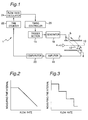
- Fig. 1 is a block diagram illustrating a control circuit for an ultrasonic flow meter of the first embodiment in which the ultrasonic flow meter is generally indicated by reference numeral 1.
- a conduit indicated by reference numeral 2 which is circular in cross section, is connected to a gas burner (not shown), in which a fluid (i.e., gas) to be supplied to the burner flows in a direction indicated by arrow 4.
- An oscillator indicated by reference numeral 6 is a generator which emits an ultrasonic wave and an oscillator indicated by reference numeral 8 is a receiver which receives the ultrasonic wave emitted from the oscillator 6.
- the oscillators 6 and 8 are mounted in the conduit 2 so as to confront each other on a line 12 which intersects a central axis 10 of the conduit 2 at a predetermined angle ⁇ .
- a trigger section indicated by reference numeral 14 outputs a trigger signal at a timing determined by a method which will be described below.
- a generator indicated by reference numeral 16 upon receiving the trigger signal, outputs a burst signal for energizing the oscillator 6.
- An amplifier indicated by reference numeral 18 amplifies a signal that the oscillator 8 has emitted when detecting an ultrasonic wave.
- a comparator indicated by reference numeral 20 generates and then outputs a signal which corresponds to a time (propagation time) from the emission of an ultrasonic wave by the oscillator 6 to the reception of the ultrasonic wave by the oscillator 8.
- a time counter indicated by reference numeral 22 calculates the propagation time according to the output signal from the comparator 20.
- a flow rate calculator indicated by reference numeral 24 calculates a flow rate of the fluid flowing in the conduit 2 from the propagation time, according to a calculation which will be described below.
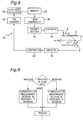
- a timing controller indicated by reference numeral 26 determines, on the basis of the flow rate, a timing at which the trigger section 14 outputs the trigger signal. In this embodiment, the timing is determined from a measuring-time interval according to a relationship (a characteristic curve) of flow rate versus measuring-time interval, shown in Fig. 2, in which the measuring-time interval decreases linearly with increasing the flow rate.
- the generator 16 When the trigger signal is transmitted from the trigger section 14, the generator 16 generates and outputs a burst signal based upon the trigger signal.
- the oscillator 6 is energized by the burst signal to emit the ultrasonic wave toward the oscillator 8.
- the ultrasonic wave is received by the oscillator 8, and a receiving signal of the oscillator 8 is amplified by the amplifier 18.
- the comparator 20 then generates a signal which corresponds to the propagation time of the ultrasonic wave and outputs the signal to the time counter 22.
- the time counter 22 calculates the propagation time and then the flow rate calculator 24 calculates the flow rate from the propagation time.
- the timing controller 26 determines a measuring-time interval corresponding to the determined flow rate on the basis of the relationship shown in Fig. 2. Specifically, the measuring-time interval is set shorter if the flow rate measured at the present time is larger than the flow rate measured at the last time, while the measuring-time interval is set longer if the flow rate has become smaller. Then, the trigger section 14 outputs a trigger signal, at the measuring-time interval which has been newly set, to energize the oscillator 6 to emit the ultrasonic wave. The ultrasonic wave is detected by the oscillator 8 and the flow rate is measured. After that, the above-described process is repeated.
- the flow rate is measured more frequently as it increases, and therefore it is possible to determined a cumulative value of the flow rates in a apparatus like gas-meter which is required to determined the cumulative value with greater presicion, in spite that measurement errors in the flow rate provide a great influences on the cumulative value.
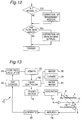
- the relationship between flow rate and measuring-time interval may be such that the measuring-time interval decreases stepwise with the increasing flow rate, as shown in Fig. 3, or may be such that the measuring-time interval is inversely proportional to the flow rate, as shown in Fig. 4.
- the measuring-time interval is determined at the timing controller 26 from the measured flow rate on the basis of a predetermined relationship between flow rate and measuring-time interval; a delay time of the trigger signal to be outputted from the trigger section 14 may be determined from the measured flow rate so that the trigger section 14 is energized after the elapse of the delay time.
- the relationship between flow rate and delay time may be any one of a linear relation (Fig. 5), a stepwise relation (Fig. 6), and an inverse relation (Fig. 7), as far as the delay time generally decreases with the increasing flow rate.
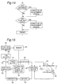
- Fig. 8 illustrates an ultrasonic flow meter 1A of the second embodiment, which includes many elements in common with the ultrasonic flow meter of Fig. 1, and like elements are designated by like reference numerals because like elements achieve similar functions, respectively.
- a storing section 28 for storing flow rate data.
- a predetermined number of flow rate values calculated by the flow rate calculator 24 are sequentially stored as flow rate data, and the data is updated by replacing the oldest flow rate data with the newest flow rate data.
- the measuring-time interval or the delay time is set at the timing controller 30 according to any one of the relationships of Figs. 2 to 4 or of Figs. 5 to 7, respectively.
- the relationships between flow rate and measuring-time interval and flow rate and delay time are preferably corrected with considering whether the flow rate is increasing or decreasing at present.
- the timing controller 30 judges from the flow rate data stored in the storing section 28 whether the flow rate is increasing on decreasing at present.
- the measuring-time interval and the delay time are corrected to be shorter than those of which to be set with respect to the same flow rate when the flow rate is stable; when the flow rates is decreasing the measuring-time interval and, the delay time is corrected to be longer.
- a trigger signal is outputted on the basis of the measuring-time interval or the delay time which has been thus corrected.
- the relationship between flow rate and measuring-time interval or delay time which has been corrected in this way is shown in Fig. 10.
- Such a correction of flow rate has an advantage that the increase in flow rate can be accurately measured, for example, even in the case that the flow rate increases sharply.
- Fig. 11 illustrates an ultrasonic flow meter 1B of a third embodiment, which meter 1B has many elements in common with the ultrasonic flow meter shown in Fig. 1, and like elements are designated by like reference numerals because like elements achieve similar functions, respectively.
- a function is added by which the measuring-time interval and the delay time are changed depending upon whether it is a time zone in which gas is typically consumed or not.
- the ultrasonic flow meter 1B comprises a clock 32, and the present time outputted from the clock 32 is delivered to a timing controller 34.
- the timing controller 34 judges from the time information whether it is in the hours when gas is consumed in large quantities or not within.
- a midnight time zone from twelve o'clock midnight to five o'clock in the morning are set as low gas-consumption time zone and the rest is set as a high gas-consumption time zone, and a determination is made whether it is in the low or high gas consumption time zone at present .
- the measuring-time interval (or the delay time) is set at a predetermined longer period of time.
- the measuring-time interval or the delay time which is set at this stage is different from and independent of the time determined by a flow rate on the basis of one of the relationships shown in Figs. 2 to 4 (or Figs. 5 to 7).
- an unnecessary power consumption can be reduced by setting the measuring-time interval or the delay time longer in the midnight hours when gas is not used. However, if the gas is consumed in midnight, the flow rate is measured at certain measuring-time intervals or with time delays corresponding to the flow rates.
- the information on month and date instead of or along with the information on time of day, may be outputted from the clock and referred to for controlling the measurement of flow rates.
- Fig. 13 illustrates an ultrasonic flow meter 1C of a fourth embodiment, which meter 1C has many elements in common with the ultrasonic flow meter shown in Fig. 1, and like elements are designated by like reference numeral because like elements achieve similar functions, respectively.
- operating states of equipments in which gas is consumed for example, a heater 36, a stove 38, and a hot-water supply 40
- the timing controller 42 judges whether the gas-consuming equipment 36, 38, or 40 is deactivated or not.
- the measuring-time interval (or the delay time) is set to a predetermined longer period of time.
- the measuring-time interval (or the delay time) which is set in this way is different from and independent of the time determined according to a flow rate on the basis of one of the relationship shown in Figs. 2 to 4 (or Figs. 5 to 7).
- a measuring-time interval or a delay time is newly set from a flow rate newly measured on the basis of one of the relationship shown in Figs. 2 to 4 or Figs. 5 to 7, respectively.
- an unnecessary power consumption can be reduced by setting the measuring-time interval or the delay time longer when gas is not consumed.
- Fig. 15 illustrates an ultrasonic flow meter 1D of a fifth embodiment, which meter 1D has many elements in common with the ultrasonic flow meter shown in Fig. 1, and like elements are designated by like reference numerals because like elements achieve similar functions, respectively.
- oscillators 44 and 46 which have both the functions of emitting and receiving ultrasonic waves are mounted in the conduit 2 so as to oppose each other on a line 12 which intersects the central axis 10 of the conduit 2 at a predetermined angle ⁇ .
- An oscillator-switching section 48 alternately switches the oscillators between one state for emitting ultrasonic waves and the other state for receiving ultrasonic waves.
- a section 50 for setting the number of repetition sets the number of times the oscillators 44 and 46 repeat the emission of an ultrasonic wave.
- a repetition controller 52 switches a first state where one oscillator 44 emits the ultrasonic wave the number of times corresponding to a flow rate and the other oscillator 46 receives the ultrasonic wave, to a second state where the other oscillator 46 emits the ultrasonic wave the same number of times and the one oscillator 44 receives the ultrasonic wave, and vice versa.
- the relationship between flow rate and the number of repetition is set so that the number of repetition generally decreases with increasing the flow rate.
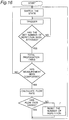
- the operation of the flow meter 1D mentioned above will be specifically described below with reference to a flow chart shown in Fig. 16.
- the number of repetition is set at (n) by the section 50 for setting the number of repetition
- the first state is established by the switching section 48.
- a trigger signal is outputted from the trigger section 14 and the burst signal is outputted from the generator 16.
- An ultrasonic wave is thereby emitted from the oscillator 44 toward the other oscillator 46 with a predetermined delay time.
- a signal received by the oscillator 46 is amplified in the amplifier 18 and compared with a reference signal in the comparator 20.
- the propagation time of the ultrasonic wave is then calculated by the time counter 22.
- the oscillator-switching section 48 is switched into the second state.
- the operation in which an ultrasonic wave is emitted from the oscillator 46 and received by the other oscillator 44 is repeated (n) times, and then the propagation times of the ultrasonic waves emitted (n) times are totaled.
- the flow rate is determined on the basis of the totals or averages of the propagation times in the first state and in the second state. Whether the flow rate has increased or decreased is then judged by comparing the flow rate newly measured with the flow rate measured last time, and the number of repetition corresponding to the flow rate newly measured is set in the section 50 for setting the number of repetition.
- the number of repetition set in this way is such that the number of repetition generally decreases with increase in the flow rate, and therefore, even a low flow rate can be accurately measured.
- ⁇ is an intersectional angle between the central axis of the conduit and the line connecting the oscillators
- n is the number of repetition.
- ⁇ Qn, (K), and (S) represent the total of the flow velocities, a correction coefficient, and the cross-sectional area of the conduit, respectively.
- the total of the flow rate values increases with increase in the number of times of the measurement.
- increasing the number of times of the measurement causes the totals of the flow velocity values and the flow rate values to increase, thus making an error included in each measurement relatively small.
- even decreasing the number of times of the measurement permits a relative measurement error to remain small because the difference between T1 and T2 is large.
- the section 50 for setting the number of repetition sets the number of repetition at a large number in the case of a low flow rate, while the section 50 sets the number of repetition at a small number in the case of a high flow rate.
- the relation between the flow rates and the numbers of repetition has only to be such that the number of repetition generally decreases with increase in the flow rate, and the relation is set so that the number of repetition decreases linearly, stepwise, or inversely with increase in the flow rate.
- one oscillator emits the ultrasonic wave (n) times and then the other oscillator emits the ultrasonic wave (n) times; however, an operation in which one oscillator emits the ultrasonic wave once and then the other oscillator emits the ultrasonic wave once may be executed as many times as the number of repetition.
- Fig. 17 illustrates an ultrasonic flow meter 1E of a sixth embodiment, which meter 1E has many elements in common with the ultrasonic flow meter shown in Fig. 1; and like elements are designated by like numerals because like elements achieve similar functions, respectively.
- the flow meter 1E comprises a breaker 54 and, as shown in the flow chart of Fig. 18, a plurality of flow rate values calculated in a flow rate calculator 24 are stored in a memory 56 as flow rate data. When the flow rate is judged to be zero from the flow rate data in the memory 56, the number of times the rate has been successively judged to be zero is stored.
- the breaker 54 is driven to cut for a predetermined period of time at least one of the powers of the trigger section, the generator 16, the amplifier 18, the comparator 20, the time counter 22, and the flow rate calculator 24. As long as a fluid does not flow, therefore, the measuring-time intervals are made long so that the power consumption can be saved.
Priority Applications (2)
| Application Number | Priority Date | Filing Date | Title |
|---|---|---|---|
| EP10182223A EP2275784A1 (en) | 1994-10-19 | 1995-10-19 | Flow Rate Measurement Method and Ultrasonic Flow Meter |
| EP10182206A EP2317287A3 (en) | 1994-10-19 | 1995-10-19 | Flow rate measurement method and ultrasonic flow meter |
Applications Claiming Priority (3)
| Application Number | Priority Date | Filing Date | Title |
|---|---|---|---|
| JP253414/94 | 1994-10-19 | ||
| JP6253414A JPH08122117A (ja) | 1994-10-19 | 1994-10-19 | 流量計測装置 |
| PCT/JP1995/002142 WO1996012933A1 (fr) | 1994-10-19 | 1995-10-19 | Procede de mesure de debit et debitmetre a ultrasons |
Publications (2)
| Publication Number | Publication Date |
|---|---|
| EP0806635A1 true EP0806635A1 (en) | 1997-11-12 |
| EP0806635A4 EP0806635A4 (zh) | 1997-11-12 |
Family
ID=17251063
Family Applications (3)
| Application Number | Title | Priority Date | Filing Date |
|---|---|---|---|
| EP95934839A Withdrawn EP0806635A1 (en) | 1994-10-19 | 1995-10-19 | Flow rate measurement method and ultrasonic flow meter |
| EP10182206A Withdrawn EP2317287A3 (en) | 1994-10-19 | 1995-10-19 | Flow rate measurement method and ultrasonic flow meter |
| EP10182223A Withdrawn EP2275784A1 (en) | 1994-10-19 | 1995-10-19 | Flow Rate Measurement Method and Ultrasonic Flow Meter |
Family Applications After (2)
| Application Number | Title | Priority Date | Filing Date |
|---|---|---|---|
| EP10182206A Withdrawn EP2317287A3 (en) | 1994-10-19 | 1995-10-19 | Flow rate measurement method and ultrasonic flow meter |
| EP10182223A Withdrawn EP2275784A1 (en) | 1994-10-19 | 1995-10-19 | Flow Rate Measurement Method and Ultrasonic Flow Meter |
Country Status (5)
| Country | Link |
|---|---|
| US (1) | US6065351A (zh) |
| EP (3) | EP0806635A1 (zh) |
| JP (2) | JPH08122117A (zh) |
| CN (10) | CN100353148C (zh) |
| WO (1) | WO1996012933A1 (zh) |
Cited By (3)
| Publication number | Priority date | Publication date | Assignee | Title |
|---|---|---|---|---|
| WO2000068649A1 (en) * | 1999-05-11 | 2000-11-16 | Matsushita Electric Industrial Co., Ltd. | Flow rate measuring device |
| WO2001001081A1 (fr) | 1999-06-24 | 2001-01-04 | Matsushita Electric Industrial Co., Ltd. | Debitmetre |
| FR2901612A1 (fr) * | 2006-04-13 | 2007-11-30 | Jean Pierre Nikolovski | Dispositif de mesure d'un parametre d'un fluide en ecoulement utilisant un transducteur a pointes |
Families Citing this family (34)
| Publication number | Priority date | Publication date | Assignee | Title |
|---|---|---|---|---|
| TWI249613B (en) * | 1998-09-11 | 2006-02-21 | Matsushita Electric Ind Co Ltd | Equipment specifying system |
| JP2000321106A (ja) * | 1999-05-17 | 2000-11-24 | Matsushita Electric Ind Co Ltd | 流量計測装置 |
| JP4556253B2 (ja) * | 1999-06-24 | 2010-10-06 | パナソニック株式会社 | 流量計 |
| KR100414913B1 (ko) * | 2002-03-04 | 2004-01-13 | 삼성전자주식회사 | 패드를 구비한 소형 경량 광케이블 |
| JP4487552B2 (ja) * | 2003-12-10 | 2010-06-23 | パナソニック株式会社 | ガス遮断装置 |
| DE102004023147A1 (de) * | 2004-05-07 | 2005-11-24 | Endress + Hauser Flowtec Ag, Reinach | Vorrichtung zur Bestimmung und/oder Überwachung des Volumen- und/oder Massendurchflusses eines Mediums |
| CN100458980C (zh) * | 2004-06-28 | 2009-02-04 | 浪潮齐鲁软件产业有限公司 | 金融税控数据可靠存储方法 |
| CN100376962C (zh) * | 2004-07-24 | 2008-03-26 | 鸿富锦精密工业(深圳)有限公司 | 导光板 |
| CN100363716C (zh) * | 2004-12-29 | 2008-01-23 | 重庆川仪总厂有限公司 | 流速模拟信号发生器 |
| US7152490B1 (en) * | 2005-08-15 | 2006-12-26 | Daniel Measurement And Control, Inc. | Methods for determining transducer delay time and transducer separation in ultrasonic flow meters |
| WO2008081610A1 (ja) | 2006-12-27 | 2008-07-10 | Panasonic Corporation | 超音波流量計 |
| JP4582105B2 (ja) * | 2007-03-26 | 2010-11-17 | パナソニック株式会社 | 使用器具判別システム |
| JP4518120B2 (ja) * | 2007-08-08 | 2010-08-04 | パナソニック株式会社 | 流量計 |
| JP5194754B2 (ja) * | 2007-12-10 | 2013-05-08 | パナソニック株式会社 | ガスメータ装置及びこの装置を用いたガス供給システム |
| CN102549394B (zh) * | 2009-09-30 | 2014-02-19 | 松下电器产业株式会社 | 流量测量装置 |
| JP2010185889A (ja) * | 2010-06-02 | 2010-08-26 | Panasonic Corp | 流量計測装置 |
| CN101886939A (zh) * | 2010-06-10 | 2010-11-17 | 宁波大学 | 一种时差法超声流量计静态漂移抑制模型及抑制方法 |
| JP5585402B2 (ja) * | 2010-11-10 | 2014-09-10 | パナソニック株式会社 | 流量計測装置 |
| EP2686643A4 (en) | 2011-03-18 | 2014-09-10 | Soneter Llc | METHODS AND APPARATUS FOR MEASURING FLUID FLOW |
| JP2013148523A (ja) * | 2012-01-23 | 2013-08-01 | Panasonic Corp | 流量計測装置 |
| US9726532B2 (en) | 2012-06-29 | 2017-08-08 | Panasonic Intellectual Property Management Co., Ltd. | Flow meter device |
| CN103278200B (zh) * | 2013-05-20 | 2017-06-06 | 新奥科技发展有限公司 | 一种气体流量检测方法 |
| CN104458916B (zh) * | 2013-09-16 | 2019-05-28 | 林德博公司 | 用于测量液体或气体流的系统或方法 |
| JP5984094B2 (ja) * | 2013-09-24 | 2016-09-06 | Smc株式会社 | 超音波流量計 |
| SG11201609863WA (en) * | 2014-05-27 | 2016-12-29 | Fisher & Paykel Healthcare Ltd | Gases mixing and measuring for a medical device |
| CN105181045B (zh) * | 2015-05-22 | 2018-04-20 | 重庆川仪自动化股份有限公司 | 超声波流量计消除温度影响声速的方法 |
| CN105181049B (zh) * | 2015-08-26 | 2018-07-31 | 北京市计量检测科学研究院 | 管道内流体流量的测量方法、测量系统及辅助测量系统 |
| EP3299774A1 (en) * | 2016-09-21 | 2018-03-28 | Kamstrup A/S | Ultrasonic flowmeter and method using partial flow measurements |
| CN107766972B (zh) * | 2017-09-30 | 2021-04-27 | 新智能源系统控制有限责任公司 | 一种能源流量延迟时间的获取方法和装置 |
| CN110542766B (zh) * | 2019-08-22 | 2021-08-20 | 中国船舶重工集团公司第七0七研究所九江分部 | 一种适用于声波多普勒测量流速的处理电路 |
| CN110455359A (zh) * | 2019-08-28 | 2019-11-15 | 杭州乾博科技有限公司 | 一种超声波水表及计量方法 |
| CN110455358A (zh) * | 2019-08-28 | 2019-11-15 | 杭州乾博科技有限公司 | 一种可计量与校验的超声波水表 |
| CN110455357A (zh) * | 2019-08-28 | 2019-11-15 | 杭州乾博科技有限公司 | 一种双向超声波水表 |
| US11340099B2 (en) * | 2020-03-26 | 2022-05-24 | Itron Global Sarl | Static fluid meter |
Citations (3)
| Publication number | Priority date | Publication date | Assignee | Title |
|---|---|---|---|---|
| US4003256A (en) * | 1975-11-17 | 1977-01-18 | Canadian Patents And Development Limited | Acoustic oscillator fluid velocity measuring device |
| US4240292A (en) * | 1978-03-03 | 1980-12-23 | Smyshlyaev Vladimir V | Method for triggering ultrasonic flow meter and ultrasonic flow meter adapted for same |
| US5329821A (en) * | 1992-05-08 | 1994-07-19 | Nusonics, Inc. | Autoranging sonic flowmeter |
Family Cites Families (27)
| Publication number | Priority date | Publication date | Assignee | Title |
|---|---|---|---|---|
| US3392574A (en) * | 1966-06-13 | 1968-07-16 | Chesapeake Instr Corp | Sing-around velocimeter |
| US3625057A (en) * | 1967-11-01 | 1971-12-07 | Mitsubishi Electric Corp | Ultrasonic flowmeter |
| US3653259A (en) * | 1970-03-06 | 1972-04-04 | Westinghouse Electric Corp | Ultrasonic flowmeter systems |
| US3720105A (en) * | 1971-03-24 | 1973-03-13 | Nusonics | Acoustic flowmeter |
| US3780577A (en) * | 1972-07-03 | 1973-12-25 | Saratoga Systems | Ultrasonic fluid speed of sound and flow meter apparatus and method |
| US3882722A (en) * | 1973-09-07 | 1975-05-13 | Westinghouse Electric Corp | Multiple time difference ultrasonic flowmeters |
| DE2517117A1 (de) * | 1975-04-18 | 1976-10-28 | Standard Elektrik Lorenz Ag | Anordnung zum bestimmen der stroemungsgeschwindigkeit von fluessigkeiten und gasen |
| US4022058A (en) * | 1975-08-07 | 1977-05-10 | Brown Alvin E | Apparatus for determining the arrival time of alternating signals |
| DE2636737C2 (de) * | 1976-08-14 | 1978-06-22 | Danfoss A/S, Nordborg (Daenemark) | Gerät zur Ultraschallmessung physikalischer Größen strömender Medien |
| JPS5829854B2 (ja) * | 1977-07-26 | 1983-06-25 | 富士電機株式会社 | 超音波式測定装置 |
| FR2408119A1 (fr) * | 1977-11-04 | 1979-06-01 | Mitsubishi Electric Corp | Debitmetre utilisant la rue des vortices de karman |
| US4246800A (en) * | 1979-10-24 | 1981-01-27 | Envirotech Corporation | Strobed power supply for an ultrasonic measuring instrument |
| DE2943810C2 (de) * | 1979-10-30 | 1982-12-09 | Erwin Sick Gmbh Optik-Elektronik, 7808 Waldkirch | Meßanordnung für die Geschwindigkeit von strömungsfähigen Medien mittels Laufzeitbestimmung von Schallwellen |
| US4372167A (en) * | 1981-01-13 | 1983-02-08 | The Perkin-Elmer Corporation | Flowmeter system with improved loop gain |
| JPS58167918A (ja) | 1982-03-29 | 1983-10-04 | Toshiba Corp | 超音波流速測定装置 |
| JPS61104224A (ja) * | 1984-10-29 | 1986-05-22 | Tokyo Keiki Co Ltd | 時間差方式超音波流量計 |
| GB8430217D0 (en) * | 1984-11-30 | 1985-01-09 | Redding R J | Electronic gas meter |
| JPS628592A (ja) * | 1985-07-04 | 1987-01-16 | 日本写真印刷株式会社 | 回路形成方法 |
| CN2047781U (zh) * | 1988-11-21 | 1989-11-15 | 中国人民解放军空军第二航空技术专科学校 | 小管径超声波流量计 |
| GB2237639B (en) * | 1989-10-31 | 1994-07-06 | British Gas Plc | Measurement system |
| JPH0535364A (ja) * | 1991-07-30 | 1993-02-12 | Hitachi Ltd | 携帯型情報処理装置 |
| FI88209C (fi) * | 1992-04-14 | 1993-04-13 | Kytoelae Instrumenttitehdas | Foerfarande och anordning vid akustisk stroemmaetning foer att foersaekra sig om den funktionsfoermaoga |
| JP3216769B2 (ja) * | 1995-03-20 | 2001-10-09 | 富士電機株式会社 | クランプオン型超音波流量計における温度圧力補償方法 |
| US5602343A (en) * | 1995-10-10 | 1997-02-11 | The Curators Of The University Of Missouri | Method of, and apparatus for, measuring the velocity of a fluid |
| US5753824A (en) * | 1996-06-12 | 1998-05-19 | Welch Allyn, Inc. | Sampling method and apparatus for use with ultrasonic flowmeters |
| US5831175A (en) * | 1996-06-12 | 1998-11-03 | Welch Allyn, Inc. | Method and apparatus for correcting temperature variations in ultrasonic flowmeters |
| US5668326A (en) * | 1996-10-04 | 1997-09-16 | Dieterich Technology Holding Corp. | Method and apparatus for detecting and aligning a signal |
-
1994
- 1994-10-19 JP JP6253414A patent/JPH08122117A/ja active Pending
-
1995
- 1995-10-19 EP EP95934839A patent/EP0806635A1/en not_active Withdrawn
- 1995-10-19 CN CNB001269984A patent/CN100353148C/zh not_active Expired - Fee Related
- 1995-10-19 EP EP10182206A patent/EP2317287A3/en not_active Withdrawn
- 1995-10-19 CN CNB200510077856XA patent/CN100565126C/zh not_active Expired - Fee Related
- 1995-10-19 EP EP10182223A patent/EP2275784A1/en not_active Withdrawn
- 1995-10-19 CN CNB031548830A patent/CN100501340C/zh not_active Expired - Fee Related
- 1995-10-19 CN CNB031548865A patent/CN100501341C/zh not_active Expired - Fee Related
- 1995-10-19 US US08/817,442 patent/US6065351A/en not_active Expired - Lifetime
- 1995-10-19 CN CNB2005100778555A patent/CN100360908C/zh not_active Expired - Fee Related
- 1995-10-19 WO PCT/JP1995/002142 patent/WO1996012933A1/ja active Application Filing
- 1995-10-19 CN CN95196677A patent/CN1074538C/zh not_active Expired - Fee Related
- 1995-10-19 CN CNB001269976A patent/CN1273804C/zh not_active Expired - Fee Related
- 1995-10-19 CN CNB2005100778574A patent/CN100370232C/zh not_active Expired - Fee Related
- 1995-10-19 JP JP51376996A patent/JP3731898B2/ja not_active Expired - Fee Related
- 1995-10-19 CN CNB031548873A patent/CN100465588C/zh not_active Expired - Fee Related
-
2000
- 2000-09-05 CN CNB001269968A patent/CN1211641C/zh not_active Expired - Fee Related
Patent Citations (3)
| Publication number | Priority date | Publication date | Assignee | Title |
|---|---|---|---|---|
| US4003256A (en) * | 1975-11-17 | 1977-01-18 | Canadian Patents And Development Limited | Acoustic oscillator fluid velocity measuring device |
| US4240292A (en) * | 1978-03-03 | 1980-12-23 | Smyshlyaev Vladimir V | Method for triggering ultrasonic flow meter and ultrasonic flow meter adapted for same |
| US5329821A (en) * | 1992-05-08 | 1994-07-19 | Nusonics, Inc. | Autoranging sonic flowmeter |
Non-Patent Citations (1)
| Title |
|---|
| See also references of WO9612933A1 * |
Cited By (6)
| Publication number | Priority date | Publication date | Assignee | Title |
|---|---|---|---|---|
| WO2000068649A1 (en) * | 1999-05-11 | 2000-11-16 | Matsushita Electric Industrial Co., Ltd. | Flow rate measuring device |
| US6748812B1 (en) | 1999-05-11 | 2004-06-15 | Matsushita Electric Industrial Co., Ltd. | Flow rate measuring apparatus |
| WO2001001081A1 (fr) | 1999-06-24 | 2001-01-04 | Matsushita Electric Industrial Co., Ltd. | Debitmetre |
| EP1243901A1 (en) * | 1999-06-24 | 2002-09-25 | Matsushita Electric Industrial Co., Ltd. | Flowmeter |
| EP1243901A4 (en) * | 1999-06-24 | 2006-07-05 | Matsushita Electric Ind Co Ltd | FLOW METER |
| FR2901612A1 (fr) * | 2006-04-13 | 2007-11-30 | Jean Pierre Nikolovski | Dispositif de mesure d'un parametre d'un fluide en ecoulement utilisant un transducteur a pointes |
Also Published As
| Publication number | Publication date |
|---|---|
| CN1273804C (zh) | 2006-09-06 |
| CN1693854A (zh) | 2005-11-09 |
| EP2317287A2 (en) | 2011-05-04 |
| CN1295235A (zh) | 2001-05-16 |
| CN1211641C (zh) | 2005-07-20 |
| CN100565126C (zh) | 2009-12-02 |
| CN1074538C (zh) | 2001-11-07 |
| EP2275784A1 (en) | 2011-01-19 |
| WO1996012933A1 (fr) | 1996-05-02 |
| CN100501341C (zh) | 2009-06-17 |
| EP2317287A3 (en) | 2012-06-13 |
| CN1508518A (zh) | 2004-06-30 |
| JPH08122117A (ja) | 1996-05-17 |
| CN100370232C (zh) | 2008-02-20 |
| CN1295236A (zh) | 2001-05-16 |
| CN1169185A (zh) | 1997-12-31 |
| JP3731898B2 (ja) | 2006-01-05 |
| US6065351A (en) | 2000-05-23 |
| CN1508517A (zh) | 2004-06-30 |
| CN100501340C (zh) | 2009-06-17 |
| EP0806635A4 (zh) | 1997-11-12 |
| CN1763482A (zh) | 2006-04-26 |
| CN1508519A (zh) | 2004-06-30 |
| CN100465588C (zh) | 2009-03-04 |
| CN1295237A (zh) | 2001-05-16 |
| CN100353148C (zh) | 2007-12-05 |
| CN100360908C (zh) | 2008-01-09 |
| CN1693853A (zh) | 2005-11-09 |
Similar Documents
| Publication | Publication Date | Title |
|---|---|---|
| EP0806635A1 (en) | Flow rate measurement method and ultrasonic flow meter | |
| US7082841B2 (en) | Ultrasonic flowmeter | |
| US20050072248A1 (en) | Ultrasonic flowmeter and ultrasonic flow rate measuring method | |
| US4300400A (en) | Acoustic flowmeter with Reynolds number compensation | |
| EP0932029B1 (en) | Acoustic flow meter | |
| JP3468233B2 (ja) | 流量計測装置 | |
| JP3427762B2 (ja) | 超音波流量計 | |
| JP3443658B2 (ja) | 流量計測装置 | |
| JP3640334B2 (ja) | 流量計およびガスメータ | |
| JPH1030947A (ja) | 超音波計測装置およびこれを含む流れ計測装置 | |
| JP3399937B1 (ja) | 流量測定方法及び超音波流量計 | |
| JP2004069524A (ja) | 流量計測装置 | |
| JP3399935B1 (ja) | 流量測定方法 | |
| JP3399938B2 (ja) | 流量測定方法及び超音波流量計 | |
| JP3399939B2 (ja) | 流量測定方法及び超音波流量計 | |
| JP3399936B2 (ja) | 超音波流量計 | |
| JP3406311B2 (ja) | 超音波流量計及びその駆動方法 | |
| JP3224295B2 (ja) | 超音波を用いた温度測定装置 | |
| JP2001304930A (ja) | 超音波ガスメータ | |
| JP2001059757A (ja) | 超音波流量計 | |
| JP4013687B2 (ja) | 流量計測装置 | |
| JP4443952B2 (ja) | 流量計測監視装置 | |
| JP2001165717A (ja) | ガス流量測定方法、ガス流量測定装置、並びに、電子式ガスメータ | |
| JP2005037325A (ja) | 流量計測装置 |
Legal Events
| Date | Code | Title | Description |
|---|---|---|---|
| PUAI | Public reference made under article 153(3) epc to a published international application that has entered the european phase |
Free format text: ORIGINAL CODE: 0009012 |
|
| PUAB | Information related to the publication of an a document modified or deleted |
Free format text: ORIGINAL CODE: 0009199EPPU |
|
| PUAF | Information related to the publication of a search report (a3 document) modified or deleted |
Free format text: ORIGINAL CODE: 0009199SEPU |
|
| PUAI | Public reference made under article 153(3) epc to a published international application that has entered the european phase |
Free format text: ORIGINAL CODE: 0009012 |
|
| 17P | Request for examination filed |
Effective date: 19970417 |
|
| A4 | Supplementary search report drawn up and despatched | ||
| AK | Designated contracting states |
Kind code of ref document: A4 Designated state(s): DE FR GB Kind code of ref document: A1 Designated state(s): DE FR GB |
|
| RAP1 | Party data changed (applicant data changed or rights of an application transferred) |
Owner name: PANASONIC CORPORATION |
|
| STAA | Information on the status of an ep patent application or granted ep patent |
Free format text: STATUS: THE APPLICATION IS DEEMED TO BE WITHDRAWN |
|
| 18D | Application deemed to be withdrawn |
Effective date: 20130103 |