EP0805023A1 - Formzylinder für eine Druckmaschine - Google Patents
Formzylinder für eine Druckmaschine Download PDFInfo
- Publication number
- EP0805023A1 EP0805023A1 EP97105897A EP97105897A EP0805023A1 EP 0805023 A1 EP0805023 A1 EP 0805023A1 EP 97105897 A EP97105897 A EP 97105897A EP 97105897 A EP97105897 A EP 97105897A EP 0805023 A1 EP0805023 A1 EP 0805023A1
- Authority
- EP
- European Patent Office
- Prior art keywords
- forme cylinder
- channel
- printing film
- pressure roller
- printing
- Prior art date
- Legal status (The legal status is an assumption and is not a legal conclusion. Google has not performed a legal analysis and makes no representation as to the accuracy of the status listed.)
- Granted
Links
Images
Classifications
-
- B—PERFORMING OPERATIONS; TRANSPORTING
- B41—PRINTING; LINING MACHINES; TYPEWRITERS; STAMPS
- B41F—PRINTING MACHINES OR PRESSES
- B41F13/00—Common details of rotary presses or machines
- B41F13/08—Cylinders
- B41F13/10—Forme cylinders
-
- B—PERFORMING OPERATIONS; TRANSPORTING
- B41—PRINTING; LINING MACHINES; TYPEWRITERS; STAMPS
- B41F—PRINTING MACHINES OR PRESSES
- B41F30/00—Devices for attaching coverings or make-ready devices; Guiding devices for coverings
- B41F30/06—Devices for attaching coverings or make-ready devices; Guiding devices for coverings attaching of endless or like continuously-fed coverings
Definitions
- the invention relates to a forme cylinder for a printing press, a printing film being used as the printing element and being drawn onto the outer surface of the forme cylinder.
- Known form cylinders contain a channel that extends at least across the image width to be printed.
- a winding and an unwinding roller for printing film are arranged in the channel or in the cavity of the forme cylinder, which is accessible through the channel. Starting from the circumference of the unwinding roll, the printing film is guided over a channel edge and over the outer surface of the forme cylinder. The printing film is fed back onto the unwinding roll into the interior of the forme cylinder via a further channel edge.
- the printing film can be pre-imaged or can be imaged in the opened state.
- the channel In order to avoid contamination of the formation or to be imaged surface of the printing film and of the parts lying inside the forme cylinder, it is known to provide the channel with a cover which essentially only allows the film to pass out of the channel or into the channel . In order to close the channel as tightly as possible, elastic sealing lips can be provided on the channel edges, which rest on the surface of the printing film.
- the invention has the advantage that during the renewal of the printing film on the outer surface of the forme cylinder, the pressure roller or the pressure rollers roll on the surface of the form cylinder when the printing film is conveyed.
- the rolling friction is so low that the imaged surface or the surface to be imaged is not damaged.
- the pressure rollers are constantly in contact with the printing film, so that the tightness of the cover is guaranteed.
- a smoothing effect on the printing film is achieved by the pressure rollers, so that the film lies exactly on the outer surface of the forme cylinder or is neatly wound onto the winding roll.
- the variant with only one pressure roller, which is assigned to the channel edge over which the printing film is unwound, can be used in solutions where the printing film is not to be used after printing.
- the variant with two pressure rollers, each of which is assigned to a channel edge can be used in solutions in which the imaged printing film is to be used again. In this case, a reversal of the elevator direction of the printing film would be readily possible for changing a printed image.
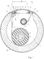
- the forme cylinder shown in FIG. 1 has a cavity 1 which is accessible via a channel 2 of width A.
- a take-up roll 3 and a take-off roll 4 for printing film 5 are each mounted on shafts 6, 7.
- the shaft 6 is coupled to a drive and the shaft 7 to a braking mechanism.
- the channel 2 is provided with a cover that extends across the width A.
- the cover consists of a frame 8 which is fastened by means of bolts 9, 10 in the front parts of the forme cylinder.
- a cover plate 13 is fastened to the frame 8 with screws 11, 12.
- the printing film 5 is guided outwards over the channel edges 14, 15 and drawn onto the outer surface 16 of the forme cylinder.
- an elastic sealing lip 17 is provided on the frame 8, which rests on the surface of the printing film 5.
- a pressure roller 18 is provided, which is arranged parallel to the channel edge 15 and is movable perpendicular to the channel edge 15.
- the bearings 19 of the pressure roller 18 are designed to be displaceable in the frame 8. Pressure pieces 20 pressing against the bearings 19 bring the pressure roller 18 into abutment against the pressure film 5, which lies against the channel edge 15.
- the printing film 5 When the take-up roll 3 is driven via the shaft 6, the printing film 5 is unwound from the take-off roll 4.
- the printing film 5 is stretched by braking the shaft 7.
- the printing film 5 slides over the channel edges 14, 15 and over the outer surface 16 of the forme cylinder.
- the sealing lip 17 and the pressure roller 18 lie directly on the printing film 5, so that the elements lying in the cavity 1 are largely shielded from the outside.
- the printing film 5 slides over the channel edge 15, the pressure roller 18 rolling on the printing film 5.
- the transport speed of the Printing film 5 and the peripheral speed of the pressure roller 18 are essentially the same, so that a slip-free rolling of the pressure roller 18 is ensured.
- the printing film 5 is not damaged by the pressure roller 18 when it emerges from the channel 2.
- the pressure roller 18 causes the printing film 5 to be smoothed before it is drawn onto the lateral surface 16, as a result of which the printing film 5 lies flat on the lateral surface 16 for an imaging process and a subsequent printing process.
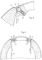
- a further pressure roller 21 can additionally be arranged in place of the sealing lip 17, which is shown in more detail in FIG. 3.
- the bearings 22 of the pressure roller 21, like the pressure roller 18, are acted upon with force with the aid of pressure pieces 23 such that the pressure roller 21 lies against the pressure film 5 entering the channel 2. This ensures that the imaging of the printing film 5 is not damaged by any sealing elements when entering the channel 2.
Landscapes
- Engineering & Computer Science (AREA)
- Mechanical Engineering (AREA)
- Supply, Installation And Extraction Of Printed Sheets Or Plates (AREA)
- Rotary Presses (AREA)
- Printing Plates And Materials Therefor (AREA)
Abstract
Description
- Die Erfindung betrifft einen Formzylinder für eine Druckmaschine, wobei als Druckelement eine Druckfolie Verwendung findet, die auf die Mantelfläche des Formzylinders aufgezogen ist. Bekannte Formzylinder enthalten einen Kanal, der mindestens über die zu druckende Bildbreite reicht. In dem Kanal bzw. in dem Hohlraum des Formzylinders, der durch den Kanal zugänglich ist, sind eine Aufwickel- und eine Abwickelrolle für Druckfolie angeordnet. Die Druckfolie ist ausgehend vom Umfang der Abwickelrolle über eine Kanalkante und über die Mantelfläche des Formzylinders geführt. Über eine weitere Kanalkante ist die Druckfolie auf die Abwickelrolle in das Innere des Formzylinders zurückgeführt. Die Druckfolie kann vorbebildert sein oder im aufgezogenen Zustand bebildert werden. Um Verschmutzungen der Bebildetung oder zu bebildernden Oberfläche der Druckfolie und der im Inneren des Formzylinders liegenden Teile zu vermeiden, ist es bekannt, den Kanal mit einer Abdeckung zu versehen, die im wesentlichen nur den Durchtritt der Folie aus dem Kanal bzw. in den Kanal zuläßt. Um den Kanal möglichst dicht zu verschließen, können an den Kanalkanten elastische Dichtlippen vorgesehen sein, die auf der Oberfläche der Druckfolie anliegen.
- Es ist ein Nachteil, daß beim Erneuern der Druckfolie auf der Mantelfläche des Formzylinders die Druckfolie an den Dichtlippen entlanggleitet. Dadurch wird die bebilderte oder zu bebildernde Oberfläche der Druckfolie beschädigt, was zu Bebilderungsfehlern und zu Druckfehlern führen kann.
- Es ist Aufgabe der Erfindung, einen Formzylinder mit einer Kanalabdeckung zu entwickeln, die einen Durchgang der Druckfolie durch den Spalt zwischen Abdeckung und Kanalkante frei von Beschädigungen ermöglicht.
- Die Aufgabe wird mit einem Formzylinder gelöst, der entsprechend den Merkmalen nach Anspruch 1 ausgebildet ist.
- Die Erfindung hat den Vorteil, daß während dem Erneuern der Druckfolie auf der Mantelfläche des Formzylinders die Andrückwalze bzw. die Andrückwalzen beim Fördern der Druckfolie auf der Oberfläche des Formzylinders abrollen. Die Rollreibung ist so gering, daß die bebilderte Oberfläche bzw. die zu bebildernde Oberfläche nicht beschädigt wird. Die Andrückwalzen liegen ständig an der Druckfolie an, so daß die Dichtheit der Abdeckung gewährleistet ist. Desweiteren wird durch die Andrückwalzen eine Glättungswirkung auf die Druckfolie erreicht, so daß die Folie exakt auf der Mantelfläche des Formzylinders aufliegt bzw. sauber auf die Aufwickelrolle aufgewickelt wird.
- Die Variante mit nur einer Andrückwalze, die der Kanalkante zugeordnet ist, über die die Druckfolie abgewickelt wird, ist bei Lösungen anwendbar, wo die Druckfolie nach dem Drucken nicht weiter verwendet werden soll. Die Variante mit zwei Andrückwalzen, die jeweils einer Kanalkante zugeordnet sind, kann bei Lösungen zum Einsatz kommen, bei denen die bebilderte Druckfolie wieder verwendet werden soll. Dabei wäre zum Wechsel eines Druckbildes eine Umkehr der Aufzugsrichtung der Druckfolie ohne weiteres möglich.
- Es ist möglich, in Bezug auf eine Kanalkante zwei oder mehrere Andrückwalzen vorzusehen, die hintereinandergeschaltet die Dichtheit der Abdeckung verbessern können.
- Die Erfindung soll nachstehend anhand von Ausführungsbeispielen noch näher erläutert werden, es zeigen:
- Fig. 1
- ein Schema eines Formzylinders mit einer Abdeckung und einer gefederten Andrückwalze,
- Fig. 2
- einen Ausschnitt aus Figur 1 mit Darstellung der Anfederung der Andrückwalze und
- Fig. 3
- ein Ausführungsbeispiel mit zwei Andrückwalzen an der Abdeckung.
- Der in Fig. 1 gezeigte Formzylinder weist einen Hohlraum 1 auf, der über einen Kanal 2 der Breite A zugänglich ist. Im Hohlraum 1 sind je eine Aufwickelrolle 3 und eine Abwickelrolle 4 für Druckfolie 5 auf Wellen 6, 7 gelagert. Die Welle 6 ist mit einem Antrieb und die Welle 7 mit einem Bremsmechanismus gekoppelt. Der Kanal 2 ist mit einer Abdeckung versehen, die über die Breite A reicht. Die Abdeckung besteht aus einem Rahmen 8, der mittels Bolzen 9, 10 in Stirnseitenteilen des Formzylinders befestigt ist. An dem Rahmen 8 ist mit Schrauben 11, 12 ein Abdeckblech 13 befestigt. Die Druckfolie 5 ist über die Kanalkanten 14, 15 nach außen geführt und auf die Mantelfläche 16 des Formzylinders aufgezogen. Auf der der Kanalkante 14 zugewandten Seite des Kanals 2 ist am Rahmen 8 eine elastische Dichtlippe 17 vorgesehen, die auf der Oberfläche der Druckfolie 5 aufliegt. Auf der der Kanalkante 15 zugewandten Seite des Kanals 2 ist, wie näher in Fig. 2 dargestellt, eine Andrückwalze 18 vorgesehen, die parallel zur Kanalkante 15 angeordnet ist und senkrecht zur Kanalkante 15 beweglich ist. Dazu sind die Lager 19 der Andrückwalze 18 im Rahmen 8 verschieblich ausgeführt. Gegen die Lager 19 drückende Druckstücke 20 bringen die Andrückwalze 18 in Anlage gegen die Druckfolie 5, welche an der Kanalkante 15 anliegt.
- Wenn die Aufwickelrolle 3 über die Welle 6 angetrieben wird, dann wird Druckfolie 5 von der Abwickelrolle 4 abgespult. Die Druckfolie 5 ist durch Bremsen der Welle 7 gespannt. Die Druckfolie 5 gleitet über die Kanalkanten 14, 15 und über die Mantelfläche 16 des Formzylinders. Die Dichtlippe 17 und die Andrückwalze 18 liegen direkt an der Druckfolie 5 an, so daß die in dem Hohlraum 1 liegenden Elemente weitestgehend nach außen abgeschirmt sind. Beim Abspulen der Druckfolie 5 von der Abwickelrolle 4 gleitet die Druckfolie 5 über die Kanalkante 15, wobei die Andrückwalze 18 an der Druckfolie 5 abrollt. Die Transportgeschwindigkeit der Druckfolie 5 und die Umfangsgeschwindigkeit der Andrückwalze 18 sind im wesentlichen gleich, so daß ein schlupffreies Abrollen der Andrückwalze 18 gewährleistet ist. Die Druckfolie 5 wird beim Austreten aus dem Kanal 2 nicht durch die Andrückwalze 18 beschädigt. Die Andrückwalze 18 bewirkt ein Glätten der Druckfolie 5, bevor diese auf die Mantelfläche 16 aufgezogen wird, wodurch die Druckfolie 5 für einen Bebilderungsvorgang und einem nachfolgenden Druckvorgang eben auf der Mantelfläche 16 aufliegt.
- Bei Lösungen, bei denen eine Wiederverwendung der Druckfolie 5 nach einem Druckvorgang vorgesehen ist, kann zusätzlich eine weitere Andruckwalze 21 an Stelle der Dichtlippe 17 angeordnet sein, was näher in Fig. 3 gezeigt ist. Die Lager 22 der Andrückwalze 21 werden ebenso wie bei der Andrückwalze 18 mit Hilfe von Druckstucken 23 so mit Kraft beaufschlagt, daß die Andrückwalze 21 an der in dem Kanal 2 einlaufenden Druckfolie 5 anliegt. Damit ist gewährleistet, daß die Bebilderung der Druckfolie 5 nicht beim Einlaufen in den Kanal 2 durch irgendwelche Dichtelemente beschädigt wird.
-
- 1
- Hohlraum
- 2
- Kanal
A Breite - 3
- Aufwickelrolle
- 4
- Abwickelrolle
- 5
- Druckfolie
- 6, 7
- Welle
- 8
- Rahmen
- 9, 10
- Bolzen
- 11, 12
- Schrauben
- 13
- Abdeckblech
- 14, 15
- Kanalkante
- 16
- Mantelfäche
- 17
- Dichtlippe
- 18
- Andrückwalze
- 19
- Lager
- 20
- Druckstücke
- 21
- Andrückwalze
- 22
- Lager
- 23
- Druckstücke
Claims (3)
- Formzylinder für eine Druckmaschine,
mit einer auf die Mantelfläche des Formzylinders aufgezogenen Druckfolie,
deren Enden jeweils an einer Aufwickel- und Abwickelrolle für die Druckfolie im Inneren des Formzylinders befestigt sind,
wobei der Formzylinder einen in Richtung einer Mantellinie verlaufenden Kanal aufweist, über dessen Kanalkanten die Druckfolie in das Innere des Formzylinders geführt ist, und
wobei weiterhin der Kanal mit einem Abdeckelement verschlossen ist,
dadurch gekennzeichnet,
daß am Abdeckelement (8, 13) mindestens eine Andrückwalze (18, 21) vorgesehen ist, die gegen die über eine Kanalkante (14, 15) aus dem Inneren (1) des Formzylinders herausgeführte Druckfolie (5) anliegt. - Formzylinder nach Anspruch 1,
dadurch gekennzeichnet,
daß die Andrückwalze (18, 21) gefedert gegen die Druckfolie (5) anliegt. - Formzylinder nach Anspruch 1,
dadurch gekennzeichnet,
daß an dem Abdeckelement (8, 13) eine weitere Andrückwalze (21) vorgesehen ist, die gegen die über die zweite Kanalkante (14) in das Innere (1) des Formzylinders hineingeführte Druckfolie anliegt.
Applications Claiming Priority (2)
| Application Number | Priority Date | Filing Date | Title |
|---|---|---|---|
| DE19617217 | 1996-04-30 | ||
| DE19617217A DE19617217A1 (de) | 1996-04-30 | 1996-04-30 | Formzylinder für eine Druckmaschine |
Publications (2)
| Publication Number | Publication Date |
|---|---|
| EP0805023A1 true EP0805023A1 (de) | 1997-11-05 |
| EP0805023B1 EP0805023B1 (de) | 1999-12-01 |
Family
ID=7792855
Family Applications (1)
| Application Number | Title | Priority Date | Filing Date |
|---|---|---|---|
| EP97105897A Expired - Lifetime EP0805023B1 (de) | 1996-04-30 | 1997-04-10 | Formzylinder für eine Druckmaschine |
Country Status (4)
| Country | Link |
|---|---|
| US (1) | US5809881A (de) |
| EP (1) | EP0805023B1 (de) |
| JP (1) | JP3805857B2 (de) |
| DE (2) | DE19617217A1 (de) |
Families Citing this family (6)
| Publication number | Priority date | Publication date | Assignee | Title |
|---|---|---|---|---|
| JPH10337839A (ja) * | 1997-06-09 | 1998-12-22 | Riso Kagaku Corp | 孔版印刷方法、孔版印刷原版、孔版印刷原版の製造方法、及び孔版印刷装置 |
| DE10000904A1 (de) | 1999-02-10 | 2000-08-17 | Heidelberger Druckmasch Ag | Verfahren und Vorrichtung zur Bereitstellung und Zuführung von Druckformen |
| US6609460B2 (en) * | 2000-11-15 | 2003-08-26 | Heidelberger Druckmaschinen Ag | Cylinder for receiving a printing form including cylinder gap with curved gap edges |
| US20070095232A1 (en) * | 2005-02-14 | 2007-05-03 | Teng Gary G | Lithographic printing press and method for on-press imaging lithographic printing plate |
| US7404357B2 (en) * | 2005-08-31 | 2008-07-29 | Heidelberger Druckmaschinen Ag | Device for pressing on a flexible printing form when it is being pulled onto a form cylinder of an offset printing press |
| US7874249B2 (en) * | 2007-03-26 | 2011-01-25 | Gary Ganghui Teng | Deactivating device and method for lithographic printing plate |
Citations (2)
| Publication number | Priority date | Publication date | Assignee | Title |
|---|---|---|---|---|
| DE4224332A1 (de) * | 1992-07-23 | 1994-01-27 | Heidelberger Druckmasch Ag | Plattenzylinder für Rotationsdruckmaschinen |
| US5355795A (en) * | 1993-08-26 | 1994-10-18 | Presstek, Inc. | Automatic plate-loading cylinder for use with plate-imaging systems |
Family Cites Families (5)
| Publication number | Priority date | Publication date | Assignee | Title |
|---|---|---|---|---|
| US618058A (en) * | 1899-01-24 | crowell | ||
| USRE19082E (en) * | 1934-02-13 | Duplicator | ||
| US912724A (en) * | 1905-03-21 | 1909-02-16 | American Lithographic Co | Printing-press. |
| DE2804556C2 (de) * | 1978-02-03 | 1983-11-24 | M.A.N.- Roland Druckmaschinen AG, 6050 Offenbach | Abnehmbare Kanalabdeckung von Zylinderkanälen bei Druckmaschinen |
| DE4303872C2 (de) * | 1992-04-24 | 1995-08-10 | Roland Man Druckmasch | Druckmaschine mit einem Formzylinder und Verfahren zur Druckvorbereitung des Formzylinders |
-
1996
- 1996-04-30 DE DE19617217A patent/DE19617217A1/de not_active Withdrawn
-
1997
- 1997-04-10 DE DE59700781T patent/DE59700781D1/de not_active Expired - Lifetime
- 1997-04-10 EP EP97105897A patent/EP0805023B1/de not_active Expired - Lifetime
- 1997-04-28 JP JP11130297A patent/JP3805857B2/ja not_active Expired - Fee Related
- 1997-04-30 US US08/845,949 patent/US5809881A/en not_active Expired - Lifetime
Patent Citations (2)
| Publication number | Priority date | Publication date | Assignee | Title |
|---|---|---|---|---|
| DE4224332A1 (de) * | 1992-07-23 | 1994-01-27 | Heidelberger Druckmasch Ag | Plattenzylinder für Rotationsdruckmaschinen |
| US5355795A (en) * | 1993-08-26 | 1994-10-18 | Presstek, Inc. | Automatic plate-loading cylinder for use with plate-imaging systems |
Also Published As
| Publication number | Publication date |
|---|---|
| EP0805023B1 (de) | 1999-12-01 |
| DE59700781D1 (de) | 2000-01-05 |
| US5809881A (en) | 1998-09-22 |
| JP3805857B2 (ja) | 2006-08-09 |
| DE19617217A1 (de) | 1997-11-06 |
| JPH1044365A (ja) | 1998-02-17 |
Similar Documents
| Publication | Publication Date | Title |
|---|---|---|
| DE60008196T2 (de) | Vorrichtung zum auswechselbares Halten und Positionnieren von Druckzylinder in eine Offsetdruckmaschine | |
| DE4331430A1 (de) | Einrichtung zum Zu- und Abführen von Druckplatten | |
| EP0805023B1 (de) | Formzylinder für eine Druckmaschine | |
| EP2116376B1 (de) | Verfahren zum Betreiben einer Druckeinheit mit mindestens einem Druckwerk | |
| EP0518053B1 (de) | Verfahren zur Herstellung bedruckter Wellpappe in grosser Arbeitsbreite sowie Anlage zur Durchführung des Verfahrens | |
| DE4434150C2 (de) | Vorrichtung zum rutschfreien Halten einer Druckfolie auf einer Mantelfläche | |
| DE60030405T2 (de) | Doppel-plattenaufwicklungsvorrichtung mit spannungeinstellung | |
| DE4307746A1 (de) | ||
| DE102007020226A1 (de) | Druckmaschine mit einer Vorrichtung zum Übertragen von bildgebenden Transferschichten | |
| DE4432817A1 (de) | Formzylinder | |
| DE4042168A1 (de) | Walze mit kraefteausuebenden bereichen | |
| DE60007245T2 (de) | Schablonendruckmaschine. | |
| DE4416296A1 (de) | Vorrichtung zum Aufziehen flexibler Druckformen | |
| DE19942617A1 (de) | Vorrichtung und Verfahren zur Durchführung eines fliegenden Plattenwechsels | |
| DE3023678C2 (de) | Verfahren und Vorrichtung zum Bedrucken flexibler Warenbahnen, wie Papier- oder Folienbahnen im Mehrfarbendruck | |
| DE2634108C3 (de) | Räderfalzapparat | |
| DE69601390T2 (de) | Falzapparatsuperstruktur | |
| DE4329125C1 (de) | Einrichtung zum Erneuern einer Druckfolie auf der Mantelfläche eines Formzylinders | |
| EP0463997B1 (de) | Kassette zum Aufwickeln von fotografischem Bandmaterial | |
| DE69800252T2 (de) | Siebabnahmevorrichtung für eine rotierende Druckmaschine mit Schutz gegen Tintenkontamination | |
| DE2365668C3 (de) | Vorrichtung zur Verarbeitung bahnförmigen Materials mit einem Rotationsdruckwerk | |
| DD258400A1 (de) | Leiteinrichtung fuer biegesteife materialien | |
| DE19508846A1 (de) | Einrichtung zum Einführen einer Druckplattenvorderkante | |
| DE10246070A1 (de) | Verfahren und Vorrichtung zum Aufspannen einer Druckfolie auf dem Formzylinder einer Druckmaschine | |
| DE19848390A1 (de) | Rollenrotationsdruckmaschine für einen schnellen Produktionswechsel |
Legal Events
| Date | Code | Title | Description |
|---|---|---|---|
| PUAI | Public reference made under article 153(3) epc to a published international application that has entered the european phase |
Free format text: ORIGINAL CODE: 0009012 |
|
| 17P | Request for examination filed |
Effective date: 19970410 |
|
| AK | Designated contracting states |
Kind code of ref document: A1 Designated state(s): BE CH DE FR GB IT LI NL |
|
| 17Q | First examination report despatched |
Effective date: 19980327 |
|
| GRAG | Despatch of communication of intention to grant |
Free format text: ORIGINAL CODE: EPIDOS AGRA |
|
| GRAG | Despatch of communication of intention to grant |
Free format text: ORIGINAL CODE: EPIDOS AGRA |
|
| GRAH | Despatch of communication of intention to grant a patent |
Free format text: ORIGINAL CODE: EPIDOS IGRA |
|
| GRAH | Despatch of communication of intention to grant a patent |
Free format text: ORIGINAL CODE: EPIDOS IGRA |
|
| GRAA | (expected) grant |
Free format text: ORIGINAL CODE: 0009210 |
|
| AK | Designated contracting states |
Kind code of ref document: B1 Designated state(s): BE CH DE FR GB IT LI NL |
|
| PG25 | Lapsed in a contracting state [announced via postgrant information from national office to epo] |
Ref country code: IT Free format text: LAPSE BECAUSE OF FAILURE TO SUBMIT A TRANSLATION OF THE DESCRIPTION OR TO PAY THE FEE WITHIN THE PRESCRIBED TIME-LIMIT;WARNING: LAPSES OF ITALIAN PATENTS WITH EFFECTIVE DATE BEFORE 2007 MAY HAVE OCCURRED AT ANY TIME BEFORE 2007. THE CORRECT EFFECTIVE DATE MAY BE DIFFERENT FROM THE ONE RECORDED. Effective date: 19991201 |
|
| REG | Reference to a national code |
Ref country code: CH Ref legal event code: EP |
|
| REF | Corresponds to: |
Ref document number: 59700781 Country of ref document: DE Date of ref document: 20000105 |
|
| GBT | Gb: translation of ep patent filed (gb section 77(6)(a)/1977) |
Effective date: 20000207 |
|
| ET | Fr: translation filed | ||
| PLBE | No opposition filed within time limit |
Free format text: ORIGINAL CODE: 0009261 |
|
| STAA | Information on the status of an ep patent application or granted ep patent |
Free format text: STATUS: NO OPPOSITION FILED WITHIN TIME LIMIT |
|
| 26N | No opposition filed | ||
| REG | Reference to a national code |
Ref country code: GB Ref legal event code: IF02 |
|
| PGFP | Annual fee paid to national office [announced via postgrant information from national office to epo] |
Ref country code: GB Payment date: 20050321 Year of fee payment: 9 |
|
| PGFP | Annual fee paid to national office [announced via postgrant information from national office to epo] |
Ref country code: FR Payment date: 20050419 Year of fee payment: 9 |
|
| PGFP | Annual fee paid to national office [announced via postgrant information from national office to epo] |
Ref country code: BE Payment date: 20050421 Year of fee payment: 9 |
|
| PGFP | Annual fee paid to national office [announced via postgrant information from national office to epo] |
Ref country code: NL Payment date: 20050425 Year of fee payment: 9 Ref country code: CH Payment date: 20050425 Year of fee payment: 9 |
|
| PG25 | Lapsed in a contracting state [announced via postgrant information from national office to epo] |
Ref country code: GB Free format text: LAPSE BECAUSE OF NON-PAYMENT OF DUE FEES Effective date: 20060410 |
|
| PG25 | Lapsed in a contracting state [announced via postgrant information from national office to epo] |
Ref country code: LI Free format text: LAPSE BECAUSE OF NON-PAYMENT OF DUE FEES Effective date: 20060430 Ref country code: CH Free format text: LAPSE BECAUSE OF NON-PAYMENT OF DUE FEES Effective date: 20060430 Ref country code: BE Free format text: LAPSE BECAUSE OF NON-PAYMENT OF DUE FEES Effective date: 20060430 |
|
| PG25 | Lapsed in a contracting state [announced via postgrant information from national office to epo] |
Ref country code: NL Free format text: LAPSE BECAUSE OF NON-PAYMENT OF DUE FEES Effective date: 20061101 |
|
| REG | Reference to a national code |
Ref country code: CH Ref legal event code: PL |
|
| GBPC | Gb: european patent ceased through non-payment of renewal fee |
Effective date: 20060410 |
|
| NLV4 | Nl: lapsed or anulled due to non-payment of the annual fee |
Effective date: 20061101 |
|
| REG | Reference to a national code |
Ref country code: FR Ref legal event code: ST Effective date: 20061230 |
|
| BERE | Be: lapsed |
Owner name: *HEIDELBERGER DRUCKMASCHINEN A.G. Effective date: 20060430 |
|
| PG25 | Lapsed in a contracting state [announced via postgrant information from national office to epo] |
Ref country code: FR Free format text: LAPSE BECAUSE OF NON-PAYMENT OF DUE FEES Effective date: 20060502 |
|
| PGFP | Annual fee paid to national office [announced via postgrant information from national office to epo] |
Ref country code: DE Payment date: 20130430 Year of fee payment: 17 |
|
| REG | Reference to a national code |
Ref country code: DE Ref legal event code: R119 Ref document number: 59700781 Country of ref document: DE |
|
| REG | Reference to a national code |
Ref country code: DE Ref legal event code: R119 Ref document number: 59700781 Country of ref document: DE Effective date: 20141101 |
|
| PG25 | Lapsed in a contracting state [announced via postgrant information from national office to epo] |
Ref country code: DE Free format text: LAPSE BECAUSE OF NON-PAYMENT OF DUE FEES Effective date: 20141101 |