EP0804027B1 - LCD-Projektor - Google Patents
LCD-Projektor Download PDFInfo
- Publication number
- EP0804027B1 EP0804027B1 EP97106733A EP97106733A EP0804027B1 EP 0804027 B1 EP0804027 B1 EP 0804027B1 EP 97106733 A EP97106733 A EP 97106733A EP 97106733 A EP97106733 A EP 97106733A EP 0804027 B1 EP0804027 B1 EP 0804027B1
- Authority
- EP
- European Patent Office
- Prior art keywords
- cylinder
- liquid crystal
- inner cylinder
- projection lens
- crystal display
- Prior art date
- Legal status (The legal status is an assumption and is not a legal conclusion. Google has not performed a legal analysis and makes no representation as to the accuracy of the status listed.)
- Expired - Lifetime
Links
Images


Classifications
-
- H—ELECTRICITY
- H04—ELECTRIC COMMUNICATION TECHNIQUE
- H04N—PICTORIAL COMMUNICATION, e.g. TELEVISION
- H04N5/00—Details of television systems
- H04N5/74—Projection arrangements for image reproduction, e.g. using eidophor
- H04N5/7416—Projection arrangements for image reproduction, e.g. using eidophor involving the use of a spatial light modulator, e.g. a light valve, controlled by a video signal
- H04N5/7441—Projection arrangements for image reproduction, e.g. using eidophor involving the use of a spatial light modulator, e.g. a light valve, controlled by a video signal the modulator being an array of liquid crystal cells
Definitions
- the present invention relates to a liquid crystal display projector according to the preamble of claim 1 and as known from US-A-5 347 324, whereby video images displayed on liquid crystal display panels and the like are projected on a screen.
- the light emitted from the light source is gathered on liquid crystal panels by means of mirrors and the like and projected on a screen through a projection lens.
- liquid crystal display projectors There are two kinds of liquid crystal display projectors, one being a 1-panel type that employs one liquid crystal display panel and the other being a 3-panel type wherein three liquid crystal display panels are used and color splitting and color combining are performed by means of dichloic mirrors and the like.
- Each respective type of the above has a projection lens protruding from the projector's main body cabinet.
- a 1-panel type liquid crystal display projector has, in general, a projection lens 41, a field lens 42, a liquid crystal display panel 43 and polarizers 45 for light incident side and light radiant side.
- the projection lens 41 There are two types in the projection lens 41, one having a fixed focus length and the other having a zooming function.
- a 3-panel type liquid crystal display projector is basically of the same structure except for having half mirrors 44 that,are additionally built in for color splitting and combining.
- Each respective liquid crystal display projector of 1-panel type and 3-panel type has generally a structure wherein a projection lens protrudes from the main body cabinet of the projector due to limitations in layout.
- the structure wherein the projection lens protrudes has often caused a problem of damaging the protruding lens and the like when a liquid crystal display projector is carried.
- the protruding projection lens has imposed many restrictions on designing liquid crystal display projectors, thereby leading to a reduction in freedom of design.
- dust easily settles on a protruding projection lens.
- US-A-5347324 already mentioned at the beginning, discloses a video projector having a projection lens being displaceable between a protruding and a retracted position relative to the housing of the video projector. When the video projector is not in use, the projection lens is contracted and stored in the housing.
- US-A-4018520 discloses a transparency projector including a focusing mechanism having an objective lens carried within a lens barrel supported within a sleeve carried by the projector housing for axial reciprocal displacement along the optical axis.
- the sleeve is provided with a means for engaging a guide rod supported within the projector housing for limiting movement of the sleeve to axial movement.
- a reversible electric motor within the housing receives slide position error signals from an automatic focusing system.
- the electric motor operates to drive a disk rotatably carried on the sleeve.
- the disk is provided with a spiral groove on one face.
- a pin fixably supported on the projector housing is arranged for engagement with the spiral groove so that upon rotation of the disk, engagement of the pin within the spiral will produce axial movement of the lens barrel supporting sleeve along the guide rod.
- the object of the invention is to provide a liquid crystal display projector allowing to protrude and retract the objective in a simple and a comfortable way.
- the main body cabinet of a liquid crystal display projector can be made simple in design, looking like a rectangular prism that is similar to the configuration of a suit case.
- a novel design as a door provided in front of the projection lens side of a liquid crystal display projector is possible, for example.
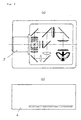
- Fig. 1 shows the main body of a 3-panel type liquid crystal display projector in an exemplary embodiment of the present invention when electric power is turned on and a diagram of the whole optical system used in the projector.
- Fig. 1(a) is a plan view and Fig. 1(b) is a front view of the liquid crystal display projector.
- Fig. 2 shows how the projector's main body looks like when electric power is turned off
- Fig. 2(a) is a plan view
- Fig. 2(b) is a front view of the projector.
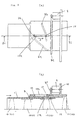
- Fig. 3 to Fig. 5 show the structure only of a projection lens as used in the liquid crystal display projector in the present exemplary embodiment.
- Fig. 3 shows a state wherein the projection lens is zoomed for wide-angle projection
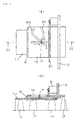
- Fig. 4 shows a state wherein the projection lens is zoomed for close-up projection
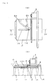
- Fig. 5 shows a state of the projection lens when electric power is turned off.
- Fig. 3(a) to Fig. 5(a) are plan views of the projection lens in each respective state thereof as mentioned in the above.
- Fig. 3(b), Fig. 4(b) and Fig. 5(b) are partially sectional views of the projection lens looked in the directions as indicated by arrows S1, S2 and S3, respectively.
- the light emitted from a lamp 1 serving as a light source is split into red, green and blue colors by a plurality of mirrors 2.
- Each respective color light thus produced is incident on a corresponding liquid crystal panel 3 serving as a liquid crystal display device.
- the composite image lights of natural color are projected on a screen to form enlarged images by a projection lens 5. All the components as mentioned above are contained inside of a main body cabinet 6.
- Each respective liquid crystal panel 3 is capable of forming images of light by means of a plurality of liquid crystal pixels, each of which is acting as a light valve to pass or block light.
- the projection lens 5 comprises:
- the intermediate cylinder 8 has a first cam groove 8a and second cam groove 8b formed on the outer surface thereof and also has gearwork 8c provided on the exterior thereof.
- the outer cylinder 10 is completely contained in the main body cabinet 6 and the end thereof is not sticking out of the main body cabinet 6.
- the shape of the first cam groove 8a and second cam groove 8b is curving so that the first inner cylinder 11 and second inner cylinder 12 are allowed to move by sliding, respectively.
- first cam groove 8a and second cam groove 8b are curving in a direction slanting from the perimeter of the circular outer surface of the intermediate cylinder 8, respectively.
- the drive motor 9 is mounted on the outer cylinder 10.
- the drive motor 9 has a gear which meshes with the gearwork 8c.
- the plurality of lenses 13 include a first lens 13 (L1) and second lens 13 (L2) installed inside the first inner cylinder 11, a third lens 13 (L3) installed inside the second inner cylinder 12 and a fourth lens 13 (L4) installed inside the outer cylinder 10.
- the rotation of the drive motor 9 causes the intermediate cylinder 8 to rotate and the rotation of the intermediate cylinder 8 causes the first inner cylinder 11 to move by sliding out of and sliding into the outer cylinder 10.
- the first inner cylinder 11 is provided with a first axis 14 which is insertable in the first cam groove 8a and the second inner cylinder 12 is provided with a second axis 15 which is insertable in the second cam groove 8b.
- the outer cylinder 10 is provided with a first elongated hole 10a, the length of which extends in the same direction as the first inner cylinder 11 slides.
- the first inner cylinder 11 is provided with a second elongated hole 11a at a position opposite to the first elongated hole 10a and the second axis 15 is inserted in the first elongated hole 10a running through the foregoing second elongated hole 11a.
- the intermediate cylinder 8 is rotated over a specified angle.
- the first axis 14 is moved in the direction indicated by an arrow "X" as shown in Fig. 3 (a) along the the first elongated hole 10a according to the rotational positions of the first cam groove 8a.
- the second inner cylinder 12 is also moved a little bit in the direction of the arrow "X" along the first elongated hole 10a of the outer cylinder 10 according to the rotational positions of the second cam groove 8b.
- the first inner cylinder 11 slides along the curving first cam groove 8a to get to a specified position and the second inner cylinder 12 slides along the curving second cam groove 8b to get to a specified position.
- the projection lens 5 is allowed to change positions thereof for zooming from wide-angle projection to close-up projection while the projection lens 5 rotating over an angle corresponding to a travel of the first axis 14 from a position "C” to position "D" along the first cam groove 8a.
- the first inner cylinder 11 retracts inside the outer cylinder 10 while the projection lens 5 rotating over an angle corresponding to a travel of the first axis 14 from a position "D" to position "E” along the first cam groove 8a.
- FIG. 3 shows the state of wide-angle projection, wherein the first inner cylinder 11 is protruding the most from the outer cylinder 10 of the projector's main body cabin 6.
- Fig. 4 shows the state of close-up projection, wherein the first inner cylinder is protruding a little bit from the outer cylinder 10 of the projector's main body cabin 6.
- the first inner cylinder 11 is retracting inside the outer cylinder 10 of the projector's main body cabin 6 and the second inner cylinder 12 is retracting in the further back inside the outer cylinder 10.
- the control of stopping angle for the drive motor 9 is made by means of a timing switch, which is not shown in the drawing.
- the first inner cylinder 11 protrudes from the main body cabin 6.
- zooming drive for wide-angle projection and close-up projection is conducted by means of a specified mechanism, which is not shown in the drawings.
- the outer cylinder 10 fixed to the main body cabin 6.
- the foregoing is not necessarily needed as far as the first inner cylinder 11 is allowed to protrude from the main body cabin 6.
- the first inner cylinder 11 protrudes from and retracts into the outer cylinder 10 and intermediate cylinder 8 by sliding.
- the projection lens 5 Protrudes from and retracts into the main body 6.
- a projection lens When electric power is turned off, a projection lens does not protrude from a projector's main body cabin and is housed inside the main body cabin, thereby preventing lenses from becoming damaged when a liquid crystal display projector is carried.
- a simpler structure needed for an operation of protruding and retracting a projection lens contributes to a reduction in production cost.
Landscapes
- Chemical & Material Sciences (AREA)
- Crystallography & Structural Chemistry (AREA)
- Engineering & Computer Science (AREA)
- Multimedia (AREA)
- Signal Processing (AREA)
- Liquid Crystal (AREA)
- Projection Apparatus (AREA)
- Transforming Electric Information Into Light Information (AREA)
Claims (6)
- Flüssigkristallanzeige-Projektor, umfassend:
ein Hauptkörpergehäuse (6), mit:wobei das Projektionsobjektiv (5) zwischen einer hervorstehenden und zurückgezogenen Position im Bezug auf das Hauptkörpergehäuse (6) verschiebbar ist,einer Lichtquelle (1);einer Gruppe von Spiegeln (2) zum Aufteilen und Kombinieren von Licht aus der Lichtquelle (1);Flüssigkristallvorrichtungen (3) zum Steuern des Durchtritts des Lichtes;einem Projektionsobjektiv (5) mit einer Funktion zum Vergrößern oder Verkleinern der von dem Flüssigkristallanzeigevorrichtung (3) erzeugten Lichtbilder;
dadurch gekennzeichnet: daß das Projektionsobjektiv (5) umfaßt:wobei der erste Innenzylinder (11) mit dem ersten Zwischenzylinder (8) so verbunden ist (14, 8a), daß dessen Drehung durch die Antriebseinrichtung (9) eine Gleitlängsbewegung des ersten Innenzylinders (11) zwischen der hervorstehenden und der zurückgezogenen Position bewirken kann.einen ringartigen Zwischenzylinder (8);eine Antriebseinrichtung (9) in einen Rotationsantriebseingriff mit den Zwischenzylinder (8);einen Außenzylinder (10), in welchem der Zwischenzylinder (8) gleitfähig aufgenommen ist;einen ersten Innenzylinder (11), welcher gleitend in den Zwischenzylinder (8) aufgenommen ist;eine Vielzahl von Linsen (L1 ... L4), welche in wenigstens einem von dem ersten Innenzylinder (11), dem Zwischenzylinder (8) und dem Außenzylinder (10) eingebaut sind; - Flüssigkristallanzeige-Projektor nach Anspruch 1, wobei das Projektionsobjektiv (5) ferner umfaßt, daß:der Außenzylinder (10 die Antriebseinrichtung (9) auf sich montiert hat und den Zwischenzylinder (8) für eine relative Rotationsbewegung aufnimmt;die Antriebseinrichtung (9) und der Zwischenzylinder (8) in einen Zahnradeingriff miteinander stehen;der Zwischenzylinder (8) einen ersten Kurvenschlitz (8a) aufweist, welcher einen auf dem Innenzylinder (11) befestigten ersten Stift (14) aufnimmt, wodurch eine Drehbewegung des Zwischenzylinders (8) eine Verschiebung des Innenzylinders (11) zwischen der hervorstehenden und zurückgezogenen Position bewirkt.
- Flüssigkristallanzeige-Projektor nach Anspruch 1 oder 2, wobei das Projektionsobjektiv (5) ferner umfaßt, daß:der Zwischenzylinder (11) einen zweiten Kurvenschlitz (8b) aufweist;ein zweiter Innenzylinder (12) gleitend innerhalb des ersten Innenzylinders (11) in einem hinteren Abschnitt davon aufgenommen ist, und einem zweiten Stift (15) aufweist, welches sich in den zweiten Kurvenschlitz (8b) erstreckt; undder zweite Innenzylinder (12) axial durch Drehung des Zwischenzylinders (8), welcher den zweite Kurvenschlitz (8b) enthält, verschiebbar ist.
- Flüssigkristallanzeige-Projektor nach einem der Ansprüche 1 bis 3, wobei:der Außenzylinder (10) ein erstes Langloch (10a) besitzt, welches sich in dessen Längsrichtung erstreckt und einen ersten Stift (14) für eine Gleitbewegung darin aufnimmt; undeine Drehung des Zwischenzylinders (8) den ersten Stift (14) zu einer Bewegung entlang des ersten Langloches (10a) veranlaßt, und dadurch den erste Innenzylinder (11) zu einer Verschiebung innerhalb des Zwischenzylinders (8) veranlaßt.
- Flüssigkristallanzeige-Projektor nach einem der Ansprüche 1 bis 4, wobei der erste Innenzylinder (11) ein zweites Langloch (11a) enthält, welches sich in dessen Axialrichtung erstreckt und an einer Position gegenüberliegend dem ersten Langloch ausgebildet ist, und die Drehung des Zwischenzylinders (8) den ersten Stift (14) zu einer Bewegung entlang dem ersten Langloch (10a) veranlaßt, und den zweiten Stift (15) zu einer Bewegung entlang sowohl dem zweiten Langloch (11a) als auch dem ersten Langloch (10a).
- Flüssigkristallanzeige-Projektor nach einem der Ansprüche 2 bis 5, wobei der erste Kurvenschlitz eine erste Position, eine zweite Position und eine dritte Position in dieser Reihenfolge besitzt, eine Bewegung des ersten Stiftes (14) aus der ersten Position in die zweite Position des ersten Kurvenschlitzes (8a) das Projektionsobjektiv (5) zu einer Einstellung veranlaßt, während das Projektionsobjektiv (5) in dem hervorstehenden Zustand belassen wird, und eine Bewegung des ersten Stiftes (14) aus der zweiten Position in die dritte Position den ersten Innenzylinder (11) veranlaßt in das Innere des Außenzylinders (10) zu gleiten.
Applications Claiming Priority (6)
| Application Number | Priority Date | Filing Date | Title |
|---|---|---|---|
| JP10505096 | 1996-04-25 | ||
| JP105050/96 | 1996-04-25 | ||
| JP10505096 | 1996-04-25 | ||
| JP33176196A JP3331888B2 (ja) | 1996-04-25 | 1996-12-12 | 液晶プロジェクション装置 |
| JP33176196 | 1996-12-12 | ||
| JP331761/96 | 1996-12-12 |
Publications (3)
| Publication Number | Publication Date |
|---|---|
| EP0804027A2 EP0804027A2 (de) | 1997-10-29 |
| EP0804027A3 EP0804027A3 (de) | 1999-07-14 |
| EP0804027B1 true EP0804027B1 (de) | 2002-07-24 |
Family
ID=26445406
Family Applications (1)
| Application Number | Title | Priority Date | Filing Date |
|---|---|---|---|
| EP97106733A Expired - Lifetime EP0804027B1 (de) | 1996-04-25 | 1997-04-23 | LCD-Projektor |
Country Status (4)
| Country | Link |
|---|---|
| US (1) | US5868483A (de) |
| EP (1) | EP0804027B1 (de) |
| JP (1) | JP3331888B2 (de) |
| DE (1) | DE69714131T2 (de) |
Families Citing this family (9)
| Publication number | Priority date | Publication date | Assignee | Title |
|---|---|---|---|---|
| AU769428B2 (en) * | 1999-01-29 | 2004-01-29 | Matsushita Electric Industrial Co., Ltd. | Liquid crystal projector |
| TW387566U (en) * | 1999-03-19 | 2000-04-11 | Acer Peripherals Inc | Projection-display apparatus with adjustable brightness and uniformity |
| JP2001092009A (ja) * | 1999-09-17 | 2001-04-06 | Sony Corp | プロジェクタ装置 |
| JP4126524B2 (ja) * | 2001-05-30 | 2008-07-30 | フジノン株式会社 | プロジェクタ装置 |
| CN101551582B (zh) * | 2008-04-02 | 2012-01-25 | 青岛海信电器股份有限公司 | 投影仪 |
| CN101661151B (zh) * | 2008-08-27 | 2012-03-14 | 鸿富锦精密工业(深圳)有限公司 | 投影机 |
| CN110049641A (zh) * | 2018-01-16 | 2019-07-23 | 孙俊华 | 一种超短焦投影仪机柜 |
| JP6648242B1 (ja) | 2018-11-13 | 2020-02-14 | 富士フイルム株式会社 | 投射装置 |
| JP6650069B1 (ja) * | 2019-10-15 | 2020-02-19 | 富士フイルム株式会社 | 投射装置 |
Family Cites Families (10)
| Publication number | Priority date | Publication date | Assignee | Title |
|---|---|---|---|---|
| US4018520A (en) * | 1975-04-15 | 1977-04-19 | Gaf Corporation | Projector focusing mechanism |
| JPH04298731A (ja) * | 1990-12-03 | 1992-10-22 | Sony Corp | ポータブルプロジェクタ |
| EP0526653A1 (de) * | 1991-02-22 | 1993-02-10 | Seiko Epson Corporation | Flüssigkristall projektor |
| JP2822696B2 (ja) * | 1991-06-27 | 1998-11-11 | 富士写真フイルム株式会社 | ビデオプロジェクタ |
| JP3267990B2 (ja) * | 1991-09-18 | 2002-03-25 | 株式会社東芝 | オンスクリーン表示回路 |
| JP3348732B2 (ja) * | 1992-04-10 | 2002-11-20 | ソニー株式会社 | プロジェクタ |
| JP3300963B2 (ja) * | 1993-10-20 | 2002-07-08 | 富士写真光機株式会社 | 撮影レンズのマウント機構 |
| JPH0933880A (ja) * | 1995-07-20 | 1997-02-07 | Fujitsu General Ltd | 液晶プロジェクタ |
| US5642927A (en) * | 1995-11-22 | 1997-07-01 | Lightware, Inc. | LCD projector with retractable projection lens assembly |
| US5669688A (en) * | 1996-06-07 | 1997-09-23 | Proxima Corporation | Display panel projector and method of using same |
-
1996
- 1996-12-12 JP JP33176196A patent/JP3331888B2/ja not_active Ceased
-
1997
- 1997-04-23 EP EP97106733A patent/EP0804027B1/de not_active Expired - Lifetime
- 1997-04-23 DE DE69714131T patent/DE69714131T2/de not_active Expired - Fee Related
- 1997-04-24 US US08/845,500 patent/US5868483A/en not_active Expired - Lifetime
Also Published As
| Publication number | Publication date |
|---|---|
| US5868483A (en) | 1999-02-09 |
| JP3331888B2 (ja) | 2002-10-07 |
| EP0804027A3 (de) | 1999-07-14 |
| DE69714131D1 (de) | 2002-08-29 |
| DE69714131T2 (de) | 2002-11-07 |
| EP0804027A2 (de) | 1997-10-29 |
| JPH1010643A (ja) | 1998-01-16 |
Similar Documents
| Publication | Publication Date | Title |
|---|---|---|
| JP3276171B2 (ja) | ズームレンズ鏡筒 | |
| US5832326A (en) | Method and apparatus for accommodating a lens in a zoom compact camera | |
| JP3238610B2 (ja) | レンズの支持構造 | |
| EP0804027B1 (de) | LCD-Projektor | |
| JPH0949961A (ja) | 可変焦点距離レンズのレンズ位置調整装置 | |
| JP2594825Y2 (ja) | レンズ鏡筒の遮光装置 | |
| EP1557715A1 (de) | Optische einheit und abbildungseinrichtung mit optischer einheit | |
| JP2593877Y2 (ja) | 画面サイズ切替機構を有するズームレンズカメラ | |
| CN100445861C (zh) | 光学单元和包括该光学单元的图像拾取装置 | |
| JP3431327B2 (ja) | 3段繰り出しズームレンズ鏡筒 | |
| JP3123723B2 (ja) | ズームレンズ組込みレンズシャッタカメラの鏡筒遮光構造 | |
| JP4714431B2 (ja) | 投射レンズ装置及びプロジェクタ装置 | |
| JP3371263B2 (ja) | レンズ鏡胴 | |
| JPH07128567A (ja) | 3段繰出ズームレンズ鏡筒 | |
| JP3288761B2 (ja) | レンズ鏡筒の定位置回動環とその支持筒の結合装置 | |
| JP3395015B2 (ja) | レンズ鏡胴 | |
| JP3757495B2 (ja) | レンズ鏡筒及びカメラ | |
| JPH0634863A (ja) | 撮影レンズ鏡筒 | |
| JPH08227086A (ja) | レンズ鏡胴 | |
| KR100229532B1 (ko) | 프로젝션 티브이 | |
| JPH1090582A (ja) | ズームレンズ鏡筒の遮光機構 | |
| JP3085735B2 (ja) | ズームレンズ鏡筒 | |
| JP2596880Y2 (ja) | ズームレンズカメラの遮光装置 | |
| JP3776157B2 (ja) | 可変焦点カメラ | |
| JPH0767002A (ja) | カメラ |
Legal Events
| Date | Code | Title | Description |
|---|---|---|---|
| PUAI | Public reference made under article 153(3) epc to a published international application that has entered the european phase |
Free format text: ORIGINAL CODE: 0009012 |
|
| AK | Designated contracting states |
Kind code of ref document: A2 Designated state(s): DE FR GB |
|
| RIN1 | Information on inventor provided before grant (corrected) |
Inventor name: HOSHINO, MAKOTO Inventor name: HASHIMUKAI, MASANARI Inventor name: AONO, SHOZO Inventor name: OKADA, TAKEHIRO |
|
| PUAL | Search report despatched |
Free format text: ORIGINAL CODE: 0009013 |
|
| AK | Designated contracting states |
Kind code of ref document: A3 Designated state(s): DE FR GB |
|
| 17P | Request for examination filed |
Effective date: 19991110 |
|
| 17Q | First examination report despatched |
Effective date: 20001102 |
|
| GRAG | Despatch of communication of intention to grant |
Free format text: ORIGINAL CODE: EPIDOS AGRA |
|
| GRAG | Despatch of communication of intention to grant |
Free format text: ORIGINAL CODE: EPIDOS AGRA |
|
| GRAH | Despatch of communication of intention to grant a patent |
Free format text: ORIGINAL CODE: EPIDOS IGRA |
|
| GRAH | Despatch of communication of intention to grant a patent |
Free format text: ORIGINAL CODE: EPIDOS IGRA |
|
| GRAA | (expected) grant |
Free format text: ORIGINAL CODE: 0009210 |
|
| AK | Designated contracting states |
Kind code of ref document: B1 Designated state(s): DE FR GB |
|
| REG | Reference to a national code |
Ref country code: GB Ref legal event code: FG4D |
|
| REF | Corresponds to: |
Ref document number: 69714131 Country of ref document: DE Date of ref document: 20020829 |
|
| ET | Fr: translation filed | ||
| PLBE | No opposition filed within time limit |
Free format text: ORIGINAL CODE: 0009261 |
|
| STAA | Information on the status of an ep patent application or granted ep patent |
Free format text: STATUS: NO OPPOSITION FILED WITHIN TIME LIMIT |
|
| 26N | No opposition filed |
Effective date: 20030425 |
|
| PGFP | Annual fee paid to national office [announced via postgrant information from national office to epo] |
Ref country code: FR Payment date: 20080312 Year of fee payment: 12 Ref country code: DE Payment date: 20080502 Year of fee payment: 12 |
|
| PGFP | Annual fee paid to national office [announced via postgrant information from national office to epo] |
Ref country code: GB Payment date: 20080423 Year of fee payment: 12 |
|
| GBPC | Gb: european patent ceased through non-payment of renewal fee |
Effective date: 20090423 |
|
| REG | Reference to a national code |
Ref country code: FR Ref legal event code: ST Effective date: 20091231 |
|
| PG25 | Lapsed in a contracting state [announced via postgrant information from national office to epo] |
Ref country code: DE Free format text: LAPSE BECAUSE OF NON-PAYMENT OF DUE FEES Effective date: 20091103 |
|
| PG25 | Lapsed in a contracting state [announced via postgrant information from national office to epo] |
Ref country code: GB Free format text: LAPSE BECAUSE OF NON-PAYMENT OF DUE FEES Effective date: 20090423 Ref country code: FR Free format text: LAPSE BECAUSE OF NON-PAYMENT OF DUE FEES Effective date: 20091222 |