EP0802097B1 - Système de ceinture de sécurité à trois points - Google Patents
Système de ceinture de sécurité à trois points Download PDFInfo
- Publication number
- EP0802097B1 EP0802097B1 EP97106591A EP97106591A EP0802097B1 EP 0802097 B1 EP0802097 B1 EP 0802097B1 EP 97106591 A EP97106591 A EP 97106591A EP 97106591 A EP97106591 A EP 97106591A EP 0802097 B1 EP0802097 B1 EP 0802097B1
- Authority
- EP
- European Patent Office
- Prior art keywords
- deflection
- safety belt
- belt system
- accordance
- point safety
- Prior art date
- Legal status (The legal status is an assumption and is not a legal conclusion. Google has not performed a legal analysis and makes no representation as to the accuracy of the status listed.)
- Expired - Lifetime
Links
- 239000002184 metal Substances 0.000 claims description 6
- 238000004519 manufacturing process Methods 0.000 description 3
- 238000005096 rolling process Methods 0.000 description 3
- 238000004804 winding Methods 0.000 description 3
- 206010063493 Premature ageing Diseases 0.000 description 1
- 208000032038 Premature aging Diseases 0.000 description 1
- 238000004873 anchoring Methods 0.000 description 1
- 238000005452 bending Methods 0.000 description 1
- 230000006378 damage Effects 0.000 description 1
- 230000006735 deficit Effects 0.000 description 1
- 238000005516 engineering process Methods 0.000 description 1
- 239000000463 material Substances 0.000 description 1
- 238000007790 scraping Methods 0.000 description 1
- 230000007704 transition Effects 0.000 description 1
Images


Classifications
-
- B—PERFORMING OPERATIONS; TRANSPORTING
- B60—VEHICLES IN GENERAL
- B60R—VEHICLES, VEHICLE FITTINGS, OR VEHICLE PARTS, NOT OTHERWISE PROVIDED FOR
- B60R22/00—Safety belts or body harnesses in vehicles
- B60R22/18—Anchoring devices
- B60R22/24—Anchoring devices secured to the side, door, or roof of the vehicle
-
- B—PERFORMING OPERATIONS; TRANSPORTING
- B60—VEHICLES IN GENERAL
- B60R—VEHICLES, VEHICLE FITTINGS, OR VEHICLE PARTS, NOT OTHERWISE PROVIDED FOR
- B60R22/00—Safety belts or body harnesses in vehicles
- B60R22/18—Anchoring devices
- B60R2022/1818—Belt guides
- B60R2022/1825—Belt guides using rollers
Definitions
- the present invention relates to a three-point seat belt system, especially for motor vehicle seats, with a seat belt that can be unwound from a reel via a deflection device arranged laterally above the seat is guided, which is a passage opening has, the lower limit by a pulley for the seat belt is formed.
- the three-point seat belt systems common in motor vehicles have a role from which the seat belt can be developed. This role is particularly at Seat belts for the front seats of a passenger car to the side of the associated seat in the floor area on the so-called B-pillar struck. Based on this role the belt is on the side above the seat on the B-pillar arranged deflection device and from there again back to a second mounting bracket for led the far end of the belt. Between the deflection device and the second floor mounting bracket is the seat belt through the implementation of a locking element led, which with one on the other the associated seat arranged buckle interacts.
- a three-point seat belt system of the type mentioned Art is known from DE-U-295 02 192.
- this well-known System comprises the deflection device a U-shaped bracket and one rotatably mounted on the parallel legs of the bracket Role.
- the role consists of a cylindrical Main section and two trumpet-shaped end sections, which has a constantly concave curved transition between the main cylindrical portion of the roller and the inner surface form the relevant leg of the bracket. Thereby the webbing should only on the relevant longitudinal edge light and steadily curved, making it easy to move Belt run can be guaranteed.
- the invention has for its object a three-point seat belt system of the type mentioned at the beginning, that the removal of the webbing facilitates and prevents impairment or destruction of the same becomes.
- the deflection device as a further role at least one to the pulley essentially has vertical guide roller, which the passage opening limited laterally.
- the leadership role is that of a lateral Limitation of the passage opening of the deflection device Wandering belt not rubbed against this side boundary becomes. Instead, the webbing sets the existing one additional leadership role in motion, creating a distinct Reduction of trigger resistance and wear of the webbing is reached. To both when unwinding the wear on both sides also when winding To reduce edge areas of the webbing are preferred two additional guide rollers are provided, which the Passage opening of the deflection device on both sides of the Limit deflection roller.
- the Jacket of the lateral guide rollers directly on the Cover the pulley. This ensures that the respective lateral guide role from that to this Side belt is immediately rotated. It also prevents the belt from being pulled into a gap becomes.
- the lateral surface of the side rollers is preferred in each case concave. This ensures in a particularly advantageous manner Way that the belt bumpless and kink-free side roll runs up.
- Another embodiment of the invention is characterized in that that the lower limit of the passage opening is formed by a deflecting surface, and that a Part of the deflection surface through the jacket at least one Deflection roller is formed.
- a deflection surface with at least one used pulley a proportionate allows easy removal of the webbing.
- the deflection surface is in the direction of passage of the webbing is gently curved and the pulleys one smaller than the radius of curvature of the deflecting surface Have radius of curvature.
- the gently curved deflection surface prevents the webbing from bending too much the deflection device, which would make it difficult to pull off.
- a smooth running of the pulleys ensures that also makes it easier to pull off the webbing becomes.
- the guide rollers are arranged distributed over the deflection surface, wherein preferably a total of two or three to one another essentially parallel pulleys are provided.
- the usage of two or three pulleys has proven to be particularly advantageous emphasized because the two or three roles, in particular if arranged over the deflection surface are, on the one hand, very little friction when pulling through ensure the webbing and on the other hand only a small one Rolling resistance is given.
- the design Cost-effective with two or three roles are possible.
- the deflection rollers and the lateral rollers are preferred stored in a plastic part, which is jacket-like can be placed on a preferably made of metal bracket part is. This also simplifies and reduces the cost of production, since the storage means for all roles in the plastic part can be trained.
- This is preferably made of metal or also a bracket part made of another stable material ensures a sufficiently firm anchoring the seat belt in the case of a heavy load, such as it occurs in an accident.
- the bearings for the deflection rollers and the side guide rollers by at least one cover part that can preferably be clipped on coverable.
- This configuration simplifies the assembly of the arrangement according to the invention, since the roles simply in Plastic part can be used and then only the cover must still be clipped on.
- the outer surfaces of the pulleys and / or the lateral According to a further embodiment of the Invention be smooth. According to another embodiment the invention, it is also possible, the lateral surfaces structured to train the movement of the Webbing to the lateral boundaries of the passage opening to influence in the deflection device.
- Fig. 1 shows the essential parts of the invention Three-point seat belt system, namely a reel 1, from which the seat belt 2 can be unwound, an upper one Deflection device 3 with a passage opening 4, through which the seat belt 2 is guided, a lower fastening fitting 5 for the end 6 of the seat belt remote from the roll 2 and a locking element 7 with an implementation 8 for the seat belt 2, which is between the upper Deflection device 3 and lower mounting bracket 5 is provided is.
- the locking element 7 does not work with one here Belt buckle shown on the roller 1 facing away Side of the associated vehicle seat, which also here is not shown together.
- the upper deflection device 3 has a deflection roller 9, which the passage opening 4 of the deflection device 3 after limited below.
- the deflection device 3 has two lateral rollers 10, which defines the passage opening 4 of the deflection device 3 limit laterally.
- the bottom of the deflection device 3 The seat belt is fed in and pulled off diagonally downwards and forwards 2 is largely free of friction in this way through the passage opening 4 of the deflection device 3 guided.
- the seat belt moves when unwinding or rolling up one side of the passage opening 4 of the deflection device 3 there, he runs onto one of the concave surfaces lateral rollers 10 so that it also laterally largely smoothly through the passage opening 4 of the Deflection device 3 is performed. Because of the concave Shell surface of the side rollers 10, which is also flush connect the jacket of the pulley 9 is also ensures that the seat belt 2 is free of bumps and kinks runs onto the side rollers 10. The burden of Belt strap is thereby greatly reduced, so that the Loading of the lateral edge areas of the webbing and the associated risk of tearing accordingly is reduced.
- the configuration of the deflection device 3 in represented individual.
- the housing 13 consists of a coatable part 14 which can be applied to the bow part 11, in which the bearings 15 and 16 for the pulley 9 and the lateral guide rollers 10 are formed.
- the second Housing part is designed as a clip-on cover part 17, which the bearings 15 and 16 of the pulley 9 and the side Guide rollers 10 covers towards the front.
- the guide roller 9 and the side Guide rollers 10 simply from the front into the associated bearings 15 and 16 can be used and are made easy by that clip part 17 held securely.
- Through this Design is both manufacture and assembly the deflection device 3 simplified.
- the one to be picked up by the deflection device 3 in the event of an accident Force is preferably formed by the metal Bracket part 11 derived from the motor vehicle.
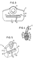
- the deflection device 3 consists of one plastic-coated, metal bracket 21, which a Has passage opening 22 for the webbing 2.
- the lower limit of the passage opening 22 is in each case by a gently in the direction of passage of the webbing 2 curved deflection surface 18 formed in the deflection rollers 20th are used in such a way that the jackets 19 of the deflection rollers 20 each form part of the deflection surface 18.
- the between the coats 19 of the guide rollers 20 remaining part the deflection surface 18 is assigned by the lower one Cross strut 23 of the bracket 21 is formed.
- FIGS. 3 and 4 there are three mutually parallel deflection rollers 20 are provided, of which one each at the belt-side and outlet-side end of the Deflection surface 18 is arranged while the third deflection roller 20 is provided in the middle of the deflection surface 18, So with her jacket 19 the apex of the curved Deflection surface 18 forms.
- the radii of curvature are that in the Bracket 21 mounted pulleys 20 relative to the radius of curvature the deflection surface 18 smaller, so that the rolling resistance the deflection rollers 20 is also small.
- the distributed arrangement of the two or three pulleys 20 over the deflecting surface 18 becomes a low withdrawal resistance of the Webbing 2 reached.
- more than three or even a single pulley with a small one Radius of curvature may be provided.
- only one Deflection roller is preferably located in the middle of the Deflection surface 18, thus forms its apex.
- the inventive Seat belt system the pull resistance of the webbing 2 kept low and the wear of the webbing 2 clearly reduced. Due to the lateral guide rollers 10 Risk of lateral tearing of the webbing 2 reduced which in known webbing by scraping the Webbing occurs on the fixed edges.
Landscapes
- Engineering & Computer Science (AREA)
- Mechanical Engineering (AREA)
- Automotive Seat Belt Assembly (AREA)
Claims (14)
- Système de ceinture de sécurité à trois points, en particulier pour siège de véhicule automobile, comprenant une ceinture de sécurité (2), susceptible d'être déroulée depuis une bobine (1) et guidée via un dispositif de renvoi (3) agencé latéralement au-dessus du siège, lequel comporte une ouverture traversante (4) dont la délimitation inférieure est formée par un rouleau de renvoi (9) pour la ceinture de sécurité (2),
caractérisé en ce que le dispositif de renvoi (3) comprend, à titre d'autres rouleaux, au moins un rouleau de guidage (10) sensiblement perpendiculaire au rouleau de renvoi (9) et délimitant latéralement l'ouverture traversante (4). - Système de ceinture de sécurité à trois points selon la revendication 1,
caractérisé en ce qu'il est prévu deux rouleaux de guidage additionnels (10) qui délimitent l'ouverture traversante (4) du dispositif de renvoi (3) sur les deux côtés. - Système de ceinture de sécurité à trois points selon l'une ou l'autre des revendications 1 et 2,
caractérisé en ce que l'enveloppe des rouleaux de guidage latéraux (10) fait respectivement immédiatement suite à l'enveloppe du rouleau de renvoi (9). - Système de ceinture de sécurité à trois points selon l'une des revendications précédentes,
caractérisé en ce que la surface enveloppe des rouleaux de guidage latéraux (10) est réalisée respectivement sous forme concave. - Système de ceinture de sécurité à trois points selon l'une des revendications précédentes,
caractérisé en ce que la délimitation inférieure de l'ouverture traversante (4) est formée par une surface de renvoi (18), et en ce qu'une partie de la surface de renvoi (18) est formée par l'enveloppe (19) d'au moins un rouleau de renvoi (20). - Système de ceinture de sécurité à trois points selon la revendication 5,
caractérisé en ce que la surface de renvoi (18) est incurvée de manière douce dans la direction de traversée de la bande de ceinture (2). - Système de ceinture de sécurité à trois points selon la revendication 6,
caractérisé en ce que les rouleaux de renvoi (20) présentent un rayon de courbure plus petit en relation au rayon de courbure de la surface de renvoi (18). - Système de ceinture de sécurité à trois points selon la revendication 7,
caractérisé en ce que les rouleaux de renvoi (20) sont agencés de manière répartie sur la surface de renvoi (18). - Système de ceinture de sécurité à trois points selon l'une des revendications 5 à 8,
caractérisé en ce qu'il est prévu au total deux ou trois rouleaux de renvoi (20) sensiblement parallèles les uns aux autres. - Système de ceinture de sécurité à trois points selon l'une des revendications précédentes,
caractérisé en ce qu'il est prévu des paliers coulissants respectifs (15, 16) pour le montage des rouleaux de guidage latéraux (10) et/ou des rouleaux de renvoi (9). - Système de ceinture de sécurité à trois points selon l'une des revendications précédentes,
caractérisé en ce que les rouleaux de renvoi (9) et les rouleaux de guidage latéraux (10) sont montés dans une pièce en matière plastique, laquelle est susceptible d'être montée à la manière d'une enveloppe sur une partie en forme d'étrier (11), réalisée de préférence en métal. - Système de ceinture de sécurité à trois points selon la revendication 11,
caractérisé en ce que les paliers (15, 16) des rouleaux de renvoi (9) et des rouleaux de guidage latéraux (10) sont susceptibles d'être recouverts par au moins une partie de couverture (17), de préférence encliquetable. - Système de ceinture de sécurité à trois points selon l'une des revendications précédentes,
caractérisé en ce que les surfaces enveloppe des rouleaux de renvoi (9, 20) et/ou des rouleaux de guidage latéraux (10) sont réalisées de manière lisse. - Système de ceinture de sécurité à trois points selon l'une des revendications 1 à 12,
caractérisé en ce que les surfaces enveloppe des rouleaux de renvoi (9, 20) et/ou des rouleaux de guidage latéraux (10) sont structurées.
Priority Applications (1)
| Application Number | Priority Date | Filing Date | Title |
|---|---|---|---|
| EP01103450A EP1101666A3 (fr) | 1996-04-19 | 1997-04-21 | Ceinture de sécurité à trois points |
Applications Claiming Priority (4)
| Application Number | Priority Date | Filing Date | Title |
|---|---|---|---|
| DE19615625 | 1996-04-19 | ||
| DE19615625 | 1996-04-19 | ||
| DE19626800 | 1996-07-03 | ||
| DE19626800A DE19626800A1 (de) | 1996-04-19 | 1996-07-03 | Dreipunkt-Sicherheitsgurtsystem mit Rollenumlenkbeschlag |
Related Child Applications (1)
| Application Number | Title | Priority Date | Filing Date |
|---|---|---|---|
| EP01103450A Division EP1101666A3 (fr) | 1996-04-19 | 1997-04-21 | Ceinture de sécurité à trois points |
Publications (3)
| Publication Number | Publication Date |
|---|---|
| EP0802097A2 EP0802097A2 (fr) | 1997-10-22 |
| EP0802097A3 EP0802097A3 (fr) | 1997-12-10 |
| EP0802097B1 true EP0802097B1 (fr) | 2001-10-04 |
Family
ID=26024932
Family Applications (1)
| Application Number | Title | Priority Date | Filing Date |
|---|---|---|---|
| EP97106591A Expired - Lifetime EP0802097B1 (fr) | 1996-04-19 | 1997-04-21 | Système de ceinture de sécurité à trois points |
Country Status (2)
| Country | Link |
|---|---|
| US (1) | US6217070B1 (fr) |
| EP (1) | EP0802097B1 (fr) |
Families Citing this family (7)
| Publication number | Priority date | Publication date | Assignee | Title |
|---|---|---|---|---|
| US6324730B1 (en) * | 1998-08-27 | 2001-12-04 | Takata Corporation | Webbing insertion member |
| US6526630B2 (en) * | 2000-02-07 | 2003-03-04 | Nsk Autoliv Co. Ltd. | Seat belt device |
| US6749150B2 (en) * | 2001-11-01 | 2004-06-15 | Key Safety Systems, Inc. | Roller web guide (or D-ring) seat belt system |
| US6837519B2 (en) * | 2002-06-21 | 2005-01-04 | General Motors Corporation | Seat belt latch plate and method of making same |
| KR100616004B1 (ko) * | 2004-08-17 | 2006-08-28 | 현대모비스 주식회사 | 차량용 시트벨트의 디링 |
| US7566075B2 (en) * | 2006-02-06 | 2009-07-28 | Toyota Motor Engineering & Manufacturing North America, Inc. | Seat belt shoulder guide |
| DE102008045999A1 (de) * | 2007-12-10 | 2009-06-18 | C. Rob. Hammerstein Gmbh & Co. Kg | Kraftfahrzeugsitz mit einer Rückenlehne und einer Gurtumlenkung |
Family Cites Families (10)
| Publication number | Priority date | Publication date | Assignee | Title |
|---|---|---|---|---|
| US4101171A (en) * | 1976-07-31 | 1978-07-18 | Toyota Jidosha Kogyo Kabushiki Kaisha | Tongue plate for seat belt device |
| DE2736115C2 (de) * | 1977-08-10 | 1984-08-09 | Repa Feinstanzwerk Gmbh, 7071 Alfdorf | Umlenkung für einen Sicherheitsgurt |
| DE2854635A1 (de) * | 1978-12-18 | 1980-10-23 | Rolf Dipl Ing Hessenbruch | Sicherheitsgurt fuer kraftfahrzeuge |
| DE2943441A1 (de) * | 1979-10-26 | 1981-04-30 | Repa Feinstanzwerk Gmbh, 7071 Alfdorf | Gurtband-bremsvorrichtung fuer sicherheitsgurtsysteme |
| DE3008371A1 (de) * | 1980-03-05 | 1981-09-17 | Hans-Hellmut Ing.(grad.) 2061 Sülfeld Ernst | Kraftfahrzeugzelle mit integrierter gurtbandumlenkung |
| DE3041103C2 (de) * | 1980-10-31 | 1984-05-10 | Repa Feinstanzwerk Gmbh, 7071 Alfdorf | Sicherheitsgurtanordnung |
| DE3144527A1 (de) * | 1981-11-10 | 1983-05-19 | Klippan GmbH, Sicherheitsgeräte, 2000 Norderstedt | Vorrichtung zur fuehrung oder umlenkung eines bandes, insbesondere fuer einen sicherheitsgurt in einem kraftfahrzeug |
| GB2174888B (en) * | 1985-05-10 | 1988-11-02 | Autoliv Dev | Improvements in or relating to a safety belt guide |
| DE29502192U1 (de) * | 1995-02-10 | 1995-05-04 | Trw Repa Gmbh | Umlenkbeschlag für Sicherheitsgurte |
| DE29510050U1 (de) * | 1995-06-21 | 1995-08-24 | Trw Repa Gmbh | Umlenkbeschlag für Sicherheitsgurte |
-
1997
- 1997-04-21 US US08/845,154 patent/US6217070B1/en not_active Expired - Fee Related
- 1997-04-21 EP EP97106591A patent/EP0802097B1/fr not_active Expired - Lifetime
Also Published As
| Publication number | Publication date |
|---|---|
| EP0802097A2 (fr) | 1997-10-22 |
| EP0802097A3 (fr) | 1997-12-10 |
| US6217070B1 (en) | 2001-04-17 |
Similar Documents
| Publication | Publication Date | Title |
|---|---|---|
| DE3218214A1 (de) | Gleitschienenfuehrung fuer fahrzeugsitze | |
| DE4339114C2 (de) | Sitzkissen eines Kraftwagensitzes | |
| EP0726187B1 (fr) | Pièce de renvoi pour ceinture de sécurité | |
| DE69628941T2 (de) | Anordnung für sicherheitsgurt | |
| DE3023093C2 (de) | Umlenkbeschlag für einen Sicherheitsgurt | |
| EP0802097B1 (fr) | Système de ceinture de sécurité à trois points | |
| DE2817741A1 (de) | Umlenkbeschlag fuer sicherheitsgurte, insbesondere fuer kraftfahrzeuge | |
| EP0941899B1 (fr) | Dispositif de ceinture de sécurité | |
| DE19913423C1 (de) | Umlenkeinrichtung für einen Sicherheitsgurt | |
| EP0963889B1 (fr) | Bobine d'enroulement pour un rétracteur de sangle d'un système de retenue d'un occupant de véhicule | |
| DE10225360C1 (de) | Rollo mit seitlicher Führung | |
| DE2257906A1 (de) | Sicherheitsgurtsystem | |
| DE3026774C2 (de) | Sicherheitsgurtsystem | |
| DE3041103C2 (de) | Sicherheitsgurtanordnung | |
| EP0941898A1 (fr) | Ferrure de renvoi pour ceintures de sécurité | |
| DE8611961U1 (de) | Umlenkbeschlag | |
| EP1101666A2 (fr) | Ceinture de sécurité à trois points | |
| DE2912248A1 (de) | Sicherheitsgurtsystem fuer fahrzeuge | |
| DE2920810C2 (de) | Sicherheitsgurtsystem für ein Kraftfahrzeug | |
| DE102006006663B3 (de) | Vorrichtung zur Gurthöhenverstellung | |
| DE3429426A1 (de) | Kraftfahrzeug-vordersitz mit einem sicherheitsgurtsystem | |
| DE3425526C2 (fr) | ||
| DE3115726A1 (de) | Sicherheitsgurt, insbesondere fuer kraftfahrzeuge | |
| DE2608046A1 (de) | Sicherheitsgurtanordnung mit gurtaufrollvorrichtung fuer fahrzeuge, insbesondere kraftfahrzeuge | |
| DE3314588A1 (de) | Passive sicherheitsgurtanordnung fuer fahrzeuge |
Legal Events
| Date | Code | Title | Description |
|---|---|---|---|
| PUAI | Public reference made under article 153(3) epc to a published international application that has entered the european phase |
Free format text: ORIGINAL CODE: 0009012 |
|
| AK | Designated contracting states |
Kind code of ref document: A2 Designated state(s): DE GB |
|
| PUAL | Search report despatched |
Free format text: ORIGINAL CODE: 0009013 |
|
| AK | Designated contracting states |
Kind code of ref document: A3 Designated state(s): DE GB |
|
| 17P | Request for examination filed |
Effective date: 19971212 |
|
| 17Q | First examination report despatched |
Effective date: 19990302 |
|
| GRAG | Despatch of communication of intention to grant |
Free format text: ORIGINAL CODE: EPIDOS AGRA |
|
| GRAG | Despatch of communication of intention to grant |
Free format text: ORIGINAL CODE: EPIDOS AGRA |
|
| GRAH | Despatch of communication of intention to grant a patent |
Free format text: ORIGINAL CODE: EPIDOS IGRA |
|
| GRAH | Despatch of communication of intention to grant a patent |
Free format text: ORIGINAL CODE: EPIDOS IGRA |
|
| GRAA | (expected) grant |
Free format text: ORIGINAL CODE: 0009210 |
|
| AK | Designated contracting states |
Kind code of ref document: B1 Designated state(s): DE GB |
|
| GBT | Gb: translation of ep patent filed (gb section 77(6)(a)/1977) |
Effective date: 20011004 |
|
| REF | Corresponds to: |
Ref document number: 59704745 Country of ref document: DE Date of ref document: 20011108 |
|
| REG | Reference to a national code |
Ref country code: GB Ref legal event code: IF02 |
|
| RAP2 | Party data changed (patent owner data changed or rights of a patent transferred) |
Owner name: TAKATA-PETRI (ULM) GMBH |
|
| PLBE | No opposition filed within time limit |
Free format text: ORIGINAL CODE: 0009261 |
|
| STAA | Information on the status of an ep patent application or granted ep patent |
Free format text: STATUS: NO OPPOSITION FILED WITHIN TIME LIMIT |
|
| 26N | No opposition filed | ||
| PGFP | Annual fee paid to national office [announced via postgrant information from national office to epo] |
Ref country code: DE Payment date: 20060413 Year of fee payment: 10 |
|
| PGFP | Annual fee paid to national office [announced via postgrant information from national office to epo] |
Ref country code: GB Payment date: 20060419 Year of fee payment: 10 |
|
| GBPC | Gb: european patent ceased through non-payment of renewal fee |
Effective date: 20070421 |
|
| PG25 | Lapsed in a contracting state [announced via postgrant information from national office to epo] |
Ref country code: DE Free format text: LAPSE BECAUSE OF NON-PAYMENT OF DUE FEES Effective date: 20071101 |
|
| PG25 | Lapsed in a contracting state [announced via postgrant information from national office to epo] |
Ref country code: GB Free format text: LAPSE BECAUSE OF NON-PAYMENT OF DUE FEES Effective date: 20070421 |