EP0802097A2 - Système de ceinture de sécurité à trois points - Google Patents
Système de ceinture de sécurité à trois points Download PDFInfo
- Publication number
- EP0802097A2 EP0802097A2 EP97106591A EP97106591A EP0802097A2 EP 0802097 A2 EP0802097 A2 EP 0802097A2 EP 97106591 A EP97106591 A EP 97106591A EP 97106591 A EP97106591 A EP 97106591A EP 0802097 A2 EP0802097 A2 EP 0802097A2
- Authority
- EP
- European Patent Office
- Prior art keywords
- seat belt
- deflection
- belt system
- rollers
- point seat
- Prior art date
- Legal status (The legal status is an assumption and is not a legal conclusion. Google has not performed a legal analysis and makes no representation as to the accuracy of the status listed.)
- Granted
Links
Images

Classifications
-
- B—PERFORMING OPERATIONS; TRANSPORTING
- B60—VEHICLES IN GENERAL
- B60R—VEHICLES, VEHICLE FITTINGS, OR VEHICLE PARTS, NOT OTHERWISE PROVIDED FOR
- B60R22/00—Safety belts or body harnesses in vehicles
- B60R22/18—Anchoring devices
- B60R22/24—Anchoring devices secured to the side, door, or roof of the vehicle
-
- B—PERFORMING OPERATIONS; TRANSPORTING
- B60—VEHICLES IN GENERAL
- B60R—VEHICLES, VEHICLE FITTINGS, OR VEHICLE PARTS, NOT OTHERWISE PROVIDED FOR
- B60R22/00—Safety belts or body harnesses in vehicles
- B60R22/18—Anchoring devices
- B60R2022/1818—Belt guides
- B60R2022/1825—Belt guides using rollers
Definitions
- the present invention relates to a three-point seat belt system, in particular for motor vehicle seats, with a seat belt that can be unwound from a roll, which is guided over a deflection device arranged laterally above the seat, which has a passage opening, the lower limit of which is formed by a deflection roller for the seat belt.
- the three-point seat belt systems customary in motor vehicles have a role from which the seat belt can be unwound. This role is struck in particular in the case of seat belts for the front seats of a passenger car on the side of the associated seat in the floor area on the so-called B-pillar.
- the belt is guided via a deflection device arranged laterally above the seat on the B-pillar and from there back to a second fastening fitting near the ground for the end of the belt remote from the roll.
- the seat belt is guided through the passage of a locking element which interacts with a belt buckle arranged on the other side of the associated seat.
- the deflection device Due to the stop of the deflection device on the B-pillar, however, the deflection device is in a rearward position with respect to the associated vehicle seat.
- the tension exerted on the webbing for putting on therefore has a force component which is directed forward in the direction of travel and which leads to the seat belt on the deflection roller moving to one side of the bushing and abutting the lateral limit there. It also happens that when the webbing is wound onto the reel, the seat belt moves in the direction of the other lateral boundary of the passage opening and abuts the lateral boundary there.
- the belt therefore rubs against these lateral boundaries, which can lead to wear and premature aging of the belt, which may even jeopardize the proper functioning of the seat belt, since there is a risk of the belt tearing sideways.
- pulling off the webbing is not yet optimally easy.
- the invention has for its object to develop a three-point seat belt system of the type mentioned so that the removal of the webbing easier and an impairment or destruction of the same is prevented.
- the deflection device has at least one further role.
- At least one guide roller which is essentially perpendicular to the deflection roller and which laterally delimits the passage opening can be provided as a further roller.
- Such an additional guide roller ensures that the belt migrating to a lateral boundary of the passage opening of the deflection device is not rubbed at this lateral boundary. Instead, the webbing sets the additional guide roller there, which significantly reduces the pulling resistance and wear of the webbing.
- two additional guide rollers are preferably provided which limit the passage opening of the deflection device on both sides of the deflection roller.
- the jacket of the lateral guide rollers directly adjoins the jacket of the deflection roller. This ensures that the respective lateral guide roller is immediately set in rotation by the belt running towards this side. It also prevents the belt from being pulled into a gap.
- the lateral surface of the side rollers is preferably concave. This ensures in a particularly advantageous manner that the belt runs onto the side roller without jolts and kinks.
- the object on which the invention is based is also achieved in that the lower limit of the passage opening is formed by a deflection surface, and that part of the deflection surface is formed by the jacket of at least one deflection roller.
- the use of a deflecting surface with at least one inserted deflection roller enables the webbing to be pulled off relatively easily. It is advantageous if the deflecting surface is gently curved in the direction of passage of the belt and the deflecting rollers have a smaller radius of curvature than the radius of curvature of the deflecting surface.
- the gently curved deflecting surface prevents the belt webbing from bending excessively in the deflecting device, which would make it difficult to pull off.
- the relatively small deflection rollers ensure that the deflection rollers run smoothly, which also makes it easier to pull off the belt.
- the deflecting rollers are arranged distributed over the deflecting surface, wherein a total of two or three deflecting rollers essentially parallel to one another are preferably provided.
- the use of two or three deflection rollers has proven to be particularly advantageous since the two or three rollers, in particular if they are arranged distributed over the deflection surface, on the one hand ensure very little friction when the webbing is pulled through and on the other hand give only a low rolling resistance is.
- the configuration with two or three roles can be carried out inexpensively.
- a plain bearing is provided for mounting the lateral rollers and / or the deflecting rollers. This is inexpensive to manufacture and therefore inexpensive.
- the deflecting rollers and / or the lateral rollers are preferably mounted in a plastic part which can be placed like a jacket on a bracket part preferably made of metal. This also simplifies and reduces the cost of manufacture, since the bearing means can be designed for all the rollers in the plastic part.
- the strap part which is preferably made of metal or another stable material, ensures that the seat belt is adequately firmly anchored in the event of a heavy load, such as occurs in an accident.
- the bearings for the deflection rollers and the lateral guide rollers can be covered by at least one cover part which can preferably be clipped on.
- the lateral surfaces of the deflection rollers and / or the lateral guide rollers can be smooth. According to another embodiment of the invention, however, it is also possible to design the lateral surfaces in a structured manner in order to influence the traveling movement of the belt strap to the lateral boundaries of the passage opening in the deflection device.
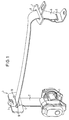
- Fig. 1 shows the essential parts of the three-point seat belt system according to the invention, namely a reel 1, from which the seat belt 2 can be unwound, an upper deflection device 3 with a passage opening 4, through which the seat belt 2 is guided, a lower fastening fitting 5 for the far end End 6 of the seat belt 2 and a locking element 7 with a bushing 8 for the seat belt 2, which is provided between the upper deflection device 3 and the lower fastening fitting 5.
- the locking element 7 interacts with a belt buckle, not shown here, on the side of the associated vehicle seat facing away from the roller 1, which is also not shown here.
- the upper deflection device 3 has a deflection roller 9, which limits the passage opening 4 of the deflection device 3 towards the bottom.
- two lateral rollers 10 are provided in the deflecting device 3, which laterally limit the passage opening 4 of the deflecting device 3.
- the bottom of the deflection device 3 In this way, the seat belt 2, which is fed in and pulled off obliquely downwards and forwards, is guided largely smoothly through the passage opening 4 of the deflection device 3.
- the seat belt moves to one side of the passage opening 4 of the deflection device 3 during unwinding or rolling up, it runs onto one of the side rollers 10 formed with a concave lateral surface, so that it is also guided laterally largely smoothly through the passage opening 4 of the deflection device 3. Due to the concave lateral surface of the side rollers 10, which also connect flush to the jacket of the deflection roller 9, it is also ensured that the seat belt 2 runs onto the side rollers 10 without bumps and kinks. The load on the belt webbing is thereby greatly reduced, so that the load on the lateral edge regions of the belt webbing and the associated risk of tearing is correspondingly reduced.
- a two-part housing 13 is placed on a bracket part 11, preferably made of metal, with a bushing 12 for a fitting bolt (not shown here) for fastening the deflection device to the motor vehicle.
- the housing 13 consists of a jacket part 14 which can be applied to the bracket part 11 and in which the bearings 15 and 16 for the deflecting roller 9 and the lateral guide rollers 10 are formed.
- the second housing part is designed as a clip-on cover part 17, which covers the bearings 15 and 16 of the deflection roller 9 and the lateral guide rollers 10 towards the front.
- the force to be absorbed by the deflection device 3 in the event of an accident is derived from the bracket part 11, which is preferably made of metal, to the motor vehicle.
- the plastic part 13 only has to absorb the forces that occur during normal operation of the seat belt 2.
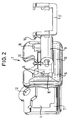
- the deflection device 3 consists in each case of a plastic-coated, metal bracket 21, which has a passage opening 22 for the webbing 2.
- the lower limit of the passage opening 22 is formed in each case by a deflecting surface 18 which is gently curved in the direction of passage of the belt webbing 2, into which deflecting rollers 20 are inserted such that the jackets 19 of the deflecting rollers 20 each form part of the deflecting surface 18.
- the part of the deflection surface 18 remaining between the shells 19 of the deflection rollers 20 is formed by the associated lower cross strut 23 of the bracket 21.
- three mutually parallel deflection rollers 20 are provided, one of which is arranged at the end of the deflection surface 18 on the belt side and one at the exit, while the third deflection roller 20 is provided in the middle of the deflection surface 18, thus with its jacket 19 forms the apex of the curved deflection surface 18.
- two mutually parallel deflection rollers 20 are provided, each of which is arranged approximately at the end of the passage opening 22 on the belt side and on the outlet side. This arrangement also allows the belt webbing 2 to be deflected with a gentle curvature.
- the radii of curvature of the deflection rollers 20 mounted in the bracket 21 are smaller than the radius of curvature of the deflection surface 18, so that the rolling resistance of the deflection rollers 20 is also small. Due to the distributed arrangement of the two or three deflecting rollers 20 over the deflecting surface 18, a low pull-off resistance of the belt webbing 2 is achieved. In principle, more than three or only a single deflection roller with a small radius of curvature can also be provided. If there is only a single deflecting roller, it is preferably located in the middle of the deflecting surface 18, thus forming its apex.
- the pull-off resistance of the webbing 2 is kept low and the wear of the webbing 2 is significantly reduced by the seat belt system according to the invention.
- the lateral guide rollers 10 reduce the risk of the belt webbing 2 tearing sideways, which occurs in known belt webbing by scraping the belt webbing at the fixed edges.
Landscapes
- Engineering & Computer Science (AREA)
- Mechanical Engineering (AREA)
- Automotive Seat Belt Assembly (AREA)
Priority Applications (1)
| Application Number | Priority Date | Filing Date | Title |
|---|---|---|---|
| EP01103450A EP1101666A3 (fr) | 1996-04-19 | 1997-04-21 | Ceinture de sécurité à trois points |
Applications Claiming Priority (4)
| Application Number | Priority Date | Filing Date | Title |
|---|---|---|---|
| DE19615625 | 1996-04-19 | ||
| DE19615625 | 1996-04-19 | ||
| DE19626800 | 1996-07-03 | ||
| DE19626800A DE19626800A1 (de) | 1996-04-19 | 1996-07-03 | Dreipunkt-Sicherheitsgurtsystem mit Rollenumlenkbeschlag |
Related Child Applications (1)
| Application Number | Title | Priority Date | Filing Date |
|---|---|---|---|
| EP01103450A Division EP1101666A3 (fr) | 1996-04-19 | 1997-04-21 | Ceinture de sécurité à trois points |
Publications (3)
| Publication Number | Publication Date |
|---|---|
| EP0802097A2 true EP0802097A2 (fr) | 1997-10-22 |
| EP0802097A3 EP0802097A3 (fr) | 1997-12-10 |
| EP0802097B1 EP0802097B1 (fr) | 2001-10-04 |
Family
ID=26024932
Family Applications (1)
| Application Number | Title | Priority Date | Filing Date |
|---|---|---|---|
| EP97106591A Expired - Lifetime EP0802097B1 (fr) | 1996-04-19 | 1997-04-21 | Système de ceinture de sécurité à trois points |
Country Status (2)
| Country | Link |
|---|---|
| US (1) | US6217070B1 (fr) |
| EP (1) | EP0802097B1 (fr) |
Families Citing this family (7)
| Publication number | Priority date | Publication date | Assignee | Title |
|---|---|---|---|---|
| US6324730B1 (en) * | 1998-08-27 | 2001-12-04 | Takata Corporation | Webbing insertion member |
| US6526630B2 (en) * | 2000-02-07 | 2003-03-04 | Nsk Autoliv Co. Ltd. | Seat belt device |
| US6749150B2 (en) * | 2001-11-01 | 2004-06-15 | Key Safety Systems, Inc. | Roller web guide (or D-ring) seat belt system |
| US6837519B2 (en) * | 2002-06-21 | 2005-01-04 | General Motors Corporation | Seat belt latch plate and method of making same |
| KR100616004B1 (ko) * | 2004-08-17 | 2006-08-28 | 현대모비스 주식회사 | 차량용 시트벨트의 디링 |
| US7566075B2 (en) * | 2006-02-06 | 2009-07-28 | Toyota Motor Engineering & Manufacturing North America, Inc. | Seat belt shoulder guide |
| DE102008045999A1 (de) * | 2007-12-10 | 2009-06-18 | C. Rob. Hammerstein Gmbh & Co. Kg | Kraftfahrzeugsitz mit einer Rückenlehne und einer Gurtumlenkung |
Family Cites Families (10)
| Publication number | Priority date | Publication date | Assignee | Title |
|---|---|---|---|---|
| US4101171A (en) * | 1976-07-31 | 1978-07-18 | Toyota Jidosha Kogyo Kabushiki Kaisha | Tongue plate for seat belt device |
| DE2736115C2 (de) * | 1977-08-10 | 1984-08-09 | Repa Feinstanzwerk Gmbh, 7071 Alfdorf | Umlenkung für einen Sicherheitsgurt |
| DE2854635A1 (de) * | 1978-12-18 | 1980-10-23 | Rolf Dipl Ing Hessenbruch | Sicherheitsgurt fuer kraftfahrzeuge |
| DE2943441A1 (de) * | 1979-10-26 | 1981-04-30 | Repa Feinstanzwerk Gmbh, 7071 Alfdorf | Gurtband-bremsvorrichtung fuer sicherheitsgurtsysteme |
| DE3008371A1 (de) * | 1980-03-05 | 1981-09-17 | Hans-Hellmut Ing.(grad.) 2061 Sülfeld Ernst | Kraftfahrzeugzelle mit integrierter gurtbandumlenkung |
| DE3041103C2 (de) * | 1980-10-31 | 1984-05-10 | Repa Feinstanzwerk Gmbh, 7071 Alfdorf | Sicherheitsgurtanordnung |
| DE3144527A1 (de) * | 1981-11-10 | 1983-05-19 | Klippan GmbH, Sicherheitsgeräte, 2000 Norderstedt | Vorrichtung zur fuehrung oder umlenkung eines bandes, insbesondere fuer einen sicherheitsgurt in einem kraftfahrzeug |
| GB2174888B (en) * | 1985-05-10 | 1988-11-02 | Autoliv Dev | Improvements in or relating to a safety belt guide |
| DE29502192U1 (de) * | 1995-02-10 | 1995-05-04 | Trw Repa Gmbh, 73553 Alfdorf | Umlenkbeschlag für Sicherheitsgurte |
| DE29510050U1 (de) * | 1995-06-21 | 1995-08-24 | TRW Repa GmbH, 00000 Alfdorf | Umlenkbeschlag für Sicherheitsgurte |
-
1997
- 1997-04-21 EP EP97106591A patent/EP0802097B1/fr not_active Expired - Lifetime
- 1997-04-21 US US08/845,154 patent/US6217070B1/en not_active Expired - Fee Related
Also Published As
| Publication number | Publication date |
|---|---|
| EP0802097B1 (fr) | 2001-10-04 |
| EP0802097A3 (fr) | 1997-12-10 |
| US6217070B1 (en) | 2001-04-17 |
Similar Documents
| Publication | Publication Date | Title |
|---|---|---|
| DE4339114C2 (de) | Sitzkissen eines Kraftwagensitzes | |
| DE102008045999A1 (de) | Kraftfahrzeugsitz mit einer Rückenlehne und einer Gurtumlenkung | |
| EP0563728A1 (fr) | Dispositif tendeur pour ceinture de sécurité de véhicules | |
| DE20102416U1 (de) | Sicherheitsgurtschloss | |
| EP0726187B1 (fr) | Pièce de renvoi pour ceinture de sécurité | |
| DE2613987A1 (de) | Leitvorrichtung fuer von einer vorratsrolle eines sicherheitsgurtsystems abspulbares und auf diese aufspulbares gurtband | |
| DE69628941T2 (de) | Anordnung für sicherheitsgurt | |
| DE2817741A1 (de) | Umlenkbeschlag fuer sicherheitsgurte, insbesondere fuer kraftfahrzeuge | |
| EP0802097A2 (fr) | Système de ceinture de sécurité à trois points | |
| DE3023093A1 (de) | Umlenkbeschlag fuer einen sicherheitsgurt | |
| DE3112458C2 (de) | Stufenweise höhenverstellbare Sicherheitsgurtumlenkung in Fahrzeugen, insbesondere Kraftfahrzeugen | |
| DE19913423C1 (de) | Umlenkeinrichtung für einen Sicherheitsgurt | |
| DE19960526B4 (de) | Umlenkarmatur für Sitzgurteinrichtung | |
| DE3872841T2 (de) | Fuehrungsoese fuer einen sicherheitsgurt. | |
| DE102004023394A1 (de) | Schlosszunge für ein Sicherheitsgurtsystem | |
| DE102019208368A1 (de) | Fahrzeugsitz mit einer integrierten Sicherheitsgurteinrichtung und einem Gurtbringer | |
| DE10210781B4 (de) | Befestigungsmittel für einen Sicherheitsgurt | |
| DE3026774C2 (de) | Sicherheitsgurtsystem | |
| DE3041103C2 (de) | Sicherheitsgurtanordnung | |
| DE3136336A1 (de) | Antriebsvorrichtung | |
| DE2541647A1 (de) | Sicherheitsgurtanordnung, insbesondere fuer kraftfahrzeuge | |
| DE3209351A1 (de) | Fahrzeug mit einem in einer laengsfuehrung gefuehrten sitz und mit sitzbefestigtem sicherheitsgurt | |
| DE69117074T2 (de) | Höhenverstellbarer sicherheitsgurt | |
| EP1101666A2 (fr) | Ceinture de sécurité à trois points | |
| DE3633901A1 (de) | Umlenkbeschlag fuer automatik-sicherheitsgurt |
Legal Events
| Date | Code | Title | Description |
|---|---|---|---|
| PUAI | Public reference made under article 153(3) epc to a published international application that has entered the european phase |
Free format text: ORIGINAL CODE: 0009012 |
|
| AK | Designated contracting states |
Kind code of ref document: A2 Designated state(s): DE GB |
|
| PUAL | Search report despatched |
Free format text: ORIGINAL CODE: 0009013 |
|
| AK | Designated contracting states |
Kind code of ref document: A3 Designated state(s): DE GB |
|
| 17P | Request for examination filed |
Effective date: 19971212 |
|
| 17Q | First examination report despatched |
Effective date: 19990302 |
|
| GRAG | Despatch of communication of intention to grant |
Free format text: ORIGINAL CODE: EPIDOS AGRA |
|
| GRAG | Despatch of communication of intention to grant |
Free format text: ORIGINAL CODE: EPIDOS AGRA |
|
| GRAH | Despatch of communication of intention to grant a patent |
Free format text: ORIGINAL CODE: EPIDOS IGRA |
|
| GRAH | Despatch of communication of intention to grant a patent |
Free format text: ORIGINAL CODE: EPIDOS IGRA |
|
| GRAA | (expected) grant |
Free format text: ORIGINAL CODE: 0009210 |
|
| AK | Designated contracting states |
Kind code of ref document: B1 Designated state(s): DE GB |
|
| GBT | Gb: translation of ep patent filed (gb section 77(6)(a)/1977) |
Effective date: 20011004 |
|
| REF | Corresponds to: |
Ref document number: 59704745 Country of ref document: DE Date of ref document: 20011108 |
|
| REG | Reference to a national code |
Ref country code: GB Ref legal event code: IF02 |
|
| RAP2 | Party data changed (patent owner data changed or rights of a patent transferred) |
Owner name: TAKATA-PETRI (ULM) GMBH |
|
| PLBE | No opposition filed within time limit |
Free format text: ORIGINAL CODE: 0009261 |
|
| STAA | Information on the status of an ep patent application or granted ep patent |
Free format text: STATUS: NO OPPOSITION FILED WITHIN TIME LIMIT |
|
| 26N | No opposition filed | ||
| PGFP | Annual fee paid to national office [announced via postgrant information from national office to epo] |
Ref country code: DE Payment date: 20060413 Year of fee payment: 10 |
|
| PGFP | Annual fee paid to national office [announced via postgrant information from national office to epo] |
Ref country code: GB Payment date: 20060419 Year of fee payment: 10 |
|
| GBPC | Gb: european patent ceased through non-payment of renewal fee |
Effective date: 20070421 |
|
| PG25 | Lapsed in a contracting state [announced via postgrant information from national office to epo] |
Ref country code: DE Free format text: LAPSE BECAUSE OF NON-PAYMENT OF DUE FEES Effective date: 20071101 |
|
| PG25 | Lapsed in a contracting state [announced via postgrant information from national office to epo] |
Ref country code: GB Free format text: LAPSE BECAUSE OF NON-PAYMENT OF DUE FEES Effective date: 20070421 |