EP0802097B1 - Three point safety belt system - Google Patents
Three point safety belt system Download PDFInfo
- Publication number
- EP0802097B1 EP0802097B1 EP97106591A EP97106591A EP0802097B1 EP 0802097 B1 EP0802097 B1 EP 0802097B1 EP 97106591 A EP97106591 A EP 97106591A EP 97106591 A EP97106591 A EP 97106591A EP 0802097 B1 EP0802097 B1 EP 0802097B1
- Authority
- EP
- European Patent Office
- Prior art keywords
- deflection
- safety belt
- belt system
- accordance
- point safety
- Prior art date
- Legal status (The legal status is an assumption and is not a legal conclusion. Google has not performed a legal analysis and makes no representation as to the accuracy of the status listed.)
- Expired - Lifetime
Links
- 239000002184 metal Substances 0.000 claims description 6
- 238000004519 manufacturing process Methods 0.000 description 3
- 238000005096 rolling process Methods 0.000 description 3
- 238000004804 winding Methods 0.000 description 3
- 206010063493 Premature ageing Diseases 0.000 description 1
- 208000032038 Premature aging Diseases 0.000 description 1
- 238000004873 anchoring Methods 0.000 description 1
- 238000005452 bending Methods 0.000 description 1
- 230000006378 damage Effects 0.000 description 1
- 230000006735 deficit Effects 0.000 description 1
- 238000005516 engineering process Methods 0.000 description 1
- 239000000463 material Substances 0.000 description 1
- 238000007790 scraping Methods 0.000 description 1
- 230000007704 transition Effects 0.000 description 1
Images


Classifications
-
- B—PERFORMING OPERATIONS; TRANSPORTING
- B60—VEHICLES IN GENERAL
- B60R—VEHICLES, VEHICLE FITTINGS, OR VEHICLE PARTS, NOT OTHERWISE PROVIDED FOR
- B60R22/00—Safety belts or body harnesses in vehicles
- B60R22/18—Anchoring devices
- B60R22/24—Anchoring devices secured to the side, door, or roof of the vehicle
-
- B—PERFORMING OPERATIONS; TRANSPORTING
- B60—VEHICLES IN GENERAL
- B60R—VEHICLES, VEHICLE FITTINGS, OR VEHICLE PARTS, NOT OTHERWISE PROVIDED FOR
- B60R22/00—Safety belts or body harnesses in vehicles
- B60R22/18—Anchoring devices
- B60R2022/1818—Belt guides
- B60R2022/1825—Belt guides using rollers
Definitions
- the present invention relates to a three-point seat belt system, especially for motor vehicle seats, with a seat belt that can be unwound from a reel via a deflection device arranged laterally above the seat is guided, which is a passage opening has, the lower limit by a pulley for the seat belt is formed.
- the three-point seat belt systems common in motor vehicles have a role from which the seat belt can be developed. This role is particularly at Seat belts for the front seats of a passenger car to the side of the associated seat in the floor area on the so-called B-pillar struck. Based on this role the belt is on the side above the seat on the B-pillar arranged deflection device and from there again back to a second mounting bracket for led the far end of the belt. Between the deflection device and the second floor mounting bracket is the seat belt through the implementation of a locking element led, which with one on the other the associated seat arranged buckle interacts.
- a three-point seat belt system of the type mentioned Art is known from DE-U-295 02 192.
- this well-known System comprises the deflection device a U-shaped bracket and one rotatably mounted on the parallel legs of the bracket Role.
- the role consists of a cylindrical Main section and two trumpet-shaped end sections, which has a constantly concave curved transition between the main cylindrical portion of the roller and the inner surface form the relevant leg of the bracket. Thereby the webbing should only on the relevant longitudinal edge light and steadily curved, making it easy to move Belt run can be guaranteed.
- the invention has for its object a three-point seat belt system of the type mentioned at the beginning, that the removal of the webbing facilitates and prevents impairment or destruction of the same becomes.
- the deflection device as a further role at least one to the pulley essentially has vertical guide roller, which the passage opening limited laterally.
- the leadership role is that of a lateral Limitation of the passage opening of the deflection device Wandering belt not rubbed against this side boundary becomes. Instead, the webbing sets the existing one additional leadership role in motion, creating a distinct Reduction of trigger resistance and wear of the webbing is reached. To both when unwinding the wear on both sides also when winding To reduce edge areas of the webbing are preferred two additional guide rollers are provided, which the Passage opening of the deflection device on both sides of the Limit deflection roller.
- the Jacket of the lateral guide rollers directly on the Cover the pulley. This ensures that the respective lateral guide role from that to this Side belt is immediately rotated. It also prevents the belt from being pulled into a gap becomes.
- the lateral surface of the side rollers is preferred in each case concave. This ensures in a particularly advantageous manner Way that the belt bumpless and kink-free side roll runs up.
- Another embodiment of the invention is characterized in that that the lower limit of the passage opening is formed by a deflecting surface, and that a Part of the deflection surface through the jacket at least one Deflection roller is formed.
- a deflection surface with at least one used pulley a proportionate allows easy removal of the webbing.
- the deflection surface is in the direction of passage of the webbing is gently curved and the pulleys one smaller than the radius of curvature of the deflecting surface Have radius of curvature.
- the gently curved deflection surface prevents the webbing from bending too much the deflection device, which would make it difficult to pull off.
- a smooth running of the pulleys ensures that also makes it easier to pull off the webbing becomes.
- the guide rollers are arranged distributed over the deflection surface, wherein preferably a total of two or three to one another essentially parallel pulleys are provided.
- the usage of two or three pulleys has proven to be particularly advantageous emphasized because the two or three roles, in particular if arranged over the deflection surface are, on the one hand, very little friction when pulling through ensure the webbing and on the other hand only a small one Rolling resistance is given.
- the design Cost-effective with two or three roles are possible.
- the deflection rollers and the lateral rollers are preferred stored in a plastic part, which is jacket-like can be placed on a preferably made of metal bracket part is. This also simplifies and reduces the cost of production, since the storage means for all roles in the plastic part can be trained.
- This is preferably made of metal or also a bracket part made of another stable material ensures a sufficiently firm anchoring the seat belt in the case of a heavy load, such as it occurs in an accident.
- the bearings for the deflection rollers and the side guide rollers by at least one cover part that can preferably be clipped on coverable.
- This configuration simplifies the assembly of the arrangement according to the invention, since the roles simply in Plastic part can be used and then only the cover must still be clipped on.
- the outer surfaces of the pulleys and / or the lateral According to a further embodiment of the Invention be smooth. According to another embodiment the invention, it is also possible, the lateral surfaces structured to train the movement of the Webbing to the lateral boundaries of the passage opening to influence in the deflection device.
- Fig. 1 shows the essential parts of the invention Three-point seat belt system, namely a reel 1, from which the seat belt 2 can be unwound, an upper one Deflection device 3 with a passage opening 4, through which the seat belt 2 is guided, a lower fastening fitting 5 for the end 6 of the seat belt remote from the roll 2 and a locking element 7 with an implementation 8 for the seat belt 2, which is between the upper Deflection device 3 and lower mounting bracket 5 is provided is.
- the locking element 7 does not work with one here Belt buckle shown on the roller 1 facing away Side of the associated vehicle seat, which also here is not shown together.
- the upper deflection device 3 has a deflection roller 9, which the passage opening 4 of the deflection device 3 after limited below.
- the deflection device 3 has two lateral rollers 10, which defines the passage opening 4 of the deflection device 3 limit laterally.
- the bottom of the deflection device 3 The seat belt is fed in and pulled off diagonally downwards and forwards 2 is largely free of friction in this way through the passage opening 4 of the deflection device 3 guided.
- the seat belt moves when unwinding or rolling up one side of the passage opening 4 of the deflection device 3 there, he runs onto one of the concave surfaces lateral rollers 10 so that it also laterally largely smoothly through the passage opening 4 of the Deflection device 3 is performed. Because of the concave Shell surface of the side rollers 10, which is also flush connect the jacket of the pulley 9 is also ensures that the seat belt 2 is free of bumps and kinks runs onto the side rollers 10. The burden of Belt strap is thereby greatly reduced, so that the Loading of the lateral edge areas of the webbing and the associated risk of tearing accordingly is reduced.
- the configuration of the deflection device 3 in represented individual.
- the housing 13 consists of a coatable part 14 which can be applied to the bow part 11, in which the bearings 15 and 16 for the pulley 9 and the lateral guide rollers 10 are formed.
- the second Housing part is designed as a clip-on cover part 17, which the bearings 15 and 16 of the pulley 9 and the side Guide rollers 10 covers towards the front.
- the guide roller 9 and the side Guide rollers 10 simply from the front into the associated bearings 15 and 16 can be used and are made easy by that clip part 17 held securely.
- Through this Design is both manufacture and assembly the deflection device 3 simplified.
- the one to be picked up by the deflection device 3 in the event of an accident Force is preferably formed by the metal Bracket part 11 derived from the motor vehicle.
- the deflection device 3 consists of one plastic-coated, metal bracket 21, which a Has passage opening 22 for the webbing 2.
- the lower limit of the passage opening 22 is in each case by a gently in the direction of passage of the webbing 2 curved deflection surface 18 formed in the deflection rollers 20th are used in such a way that the jackets 19 of the deflection rollers 20 each form part of the deflection surface 18.
- the between the coats 19 of the guide rollers 20 remaining part the deflection surface 18 is assigned by the lower one Cross strut 23 of the bracket 21 is formed.
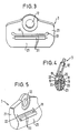
- FIGS. 3 and 4 there are three mutually parallel deflection rollers 20 are provided, of which one each at the belt-side and outlet-side end of the Deflection surface 18 is arranged while the third deflection roller 20 is provided in the middle of the deflection surface 18, So with her jacket 19 the apex of the curved Deflection surface 18 forms.
- the radii of curvature are that in the Bracket 21 mounted pulleys 20 relative to the radius of curvature the deflection surface 18 smaller, so that the rolling resistance the deflection rollers 20 is also small.
- the distributed arrangement of the two or three pulleys 20 over the deflecting surface 18 becomes a low withdrawal resistance of the Webbing 2 reached.
- more than three or even a single pulley with a small one Radius of curvature may be provided.
- only one Deflection roller is preferably located in the middle of the Deflection surface 18, thus forms its apex.
- the inventive Seat belt system the pull resistance of the webbing 2 kept low and the wear of the webbing 2 clearly reduced. Due to the lateral guide rollers 10 Risk of lateral tearing of the webbing 2 reduced which in known webbing by scraping the Webbing occurs on the fixed edges.
Landscapes
- Engineering & Computer Science (AREA)
- Mechanical Engineering (AREA)
- Automotive Seat Belt Assembly (AREA)
Description
Die vorliegende Erfindung betrifft ein Dreipunkt-Sicherheitsgurtsystem, insbesondere für Kraftfahrzeugsitze, mit einem von einer Rolle abwickelbaren Sicherheitsgurt, der über eine seitlich oberhalb des Sitzes angeordnete Umlenkeinrichtung geführt ist, welche eine Durchtrittsöffnung aufweist, deren untere Begrenzung durch eine Umlenkrolle für den Sicherheitsgurt gebildet wird.The present invention relates to a three-point seat belt system, especially for motor vehicle seats, with a seat belt that can be unwound from a reel via a deflection device arranged laterally above the seat is guided, which is a passage opening has, the lower limit by a pulley for the seat belt is formed.
Die in Kraftfahrzeugen üblichen Dreipunkt-Sicherheitsgurtsysteme weisen eine Rolle auf, von welcher der Sicherheitsgurt abwickelbar ist. Diese Rolle ist insbesondere bei Sicherheitsgurten für die Vordersitze eines Personenwagens seitlich des zugehörigen Sitzes im Bodenbereich an der sogenannten B-Säule angeschlagen. Ausgehend von dieser Rolle ist der Gurt über eine seitlich oberhalb des Sitzes an der B-Säule angeordnete Umlenkeinrichtung und von dort wieder zurück zu einem zweiten bodennahen Befestigungsbeschlag für das rollenferne Ende des Gurtes geführt. Zwischen der Umlenkeinrichtung und dem zweiten bodennahen Befestigungsbeschlag ist der Sicherheitsgurt durch die Durchführung eines Riegelelements geführt, welches mit einem auf der anderen Seite des zugehörigen Sitzes angeordneten Gurtschloß zusammenwirkt.The three-point seat belt systems common in motor vehicles have a role from which the seat belt can be developed. This role is particularly at Seat belts for the front seats of a passenger car to the side of the associated seat in the floor area on the so-called B-pillar struck. Based on this role the belt is on the side above the seat on the B-pillar arranged deflection device and from there again back to a second mounting bracket for led the far end of the belt. Between the deflection device and the second floor mounting bracket is the seat belt through the implementation of a locking element led, which with one on the other the associated seat arranged buckle interacts.
Beim Auf- und Abwickeln eines solchen Sicherheitsgurtes wird das Gurtband durch die Durchtrittsöffnung der Umlenkeinrichtung gezogen. Um die hierbei auftretende, das Gurtband belastende und damit zu einem Verschleiß führende Reibung möglichst gering zu halten, ist es bereits bekannt, in der Umlenkeinrichtung eine Umlenkrolle vorzusehen, über welche der Sicherheitsgurt geführt ist. Diese Umlenkrolle ist in der Umlenkeinrichtung so angeordnet, daß sie die untere Begrenzung der Durchtrittsöffnung bildet. Der Mantel der einen entsprechend großen Durchmesser aufweisenden Umlenkrolle bildet somit die Umlenkfläche für den Sicherheitsgurt. Das von unten von der Abwickelrolle nachgelieferte und im wesentlichen auch nach unten abgezogene Gurtband kann dadurch weitgehend reibungsfrei geführt werden.When winding and unwinding such a seat belt the webbing through the passage opening of the deflection device drawn. To the occurring belt strap burdensome and thus leading to wear To keep it as low as possible, it is already known in the Deflection device to provide a deflection roller, via which the seat belt is guided. This pulley is in the deflection device arranged so that it is the lower Limits the passage opening forms. The coat of the a correspondingly large diameter pulley thus forms the deflection surface for the seat belt. The one supplied from below by the unwinding roll and in can also significantly pulled down webbing largely run smoothly.
Aufgrund des Anschlages der Umlenkeinrichtung an der B-Säule befindet sich die Umlenkeinrichtung in bezug auf den zugehörigen Fahrzeugsitz jedoch in einer rückwärtigen Position. Der auf das Gurtband zum Anlegen ausgeübte Zug weist daher eine in Fahrtrichtung gesehen nach vorne gerichtete Kraftkomponente auf, die dazu führt, daß der Sicherheitsgurt auf der Umlenkrolle zu einer Seite der Durchführung hin wandert und an der dortigen seitlichen Begrenzung anstößt. Ebenso kommt es vor, daß beim Aufwickeln des Gurtbandes auf die Rolle der Sicherheitsgurt in Richtung auf die andere seitliche Begrenzung der Durchtrittsöffnung wandert und an die dortige seitliche Begrenzung anstößt. Der Gurt reibt daher an diesen seitlichen Begrenzungen, was zu einem Verschleiß und einer vorzeitigen Alterung des Gurtes führen kann, die möglicherweise sogar die einwandfreie Funktion des Sicherheitsgurtes gefährdet, da die Gefahr besteht, daß der Gurt seitlich einreißt. Zudem ist das Abziehen des Gurtbandes noch nicht optimal leicht.Due to the stop of the deflection device on the B-pillar is the deflection device with respect to the associated Vehicle seat, however, in a rearward position. The tension exerted on the webbing for putting on therefore points a force component facing forward in the direction of travel on, which causes the seat belt to be on the deflection roller moves to one side of the bushing and abuts the lateral boundary there. As well it happens that when winding the webbing on the Roll the seat belt towards the other side Limitation of the passage opening and migrates to the abuts there lateral limitation. The belt therefore rubs at these side boundaries, causing wear and lead to premature aging of the belt possibly even the proper functioning of the seat belt endangered, since there is a risk that the belt tears laterally. In addition, the webbing is pulled off not yet optimally easy.
Ein Dreipunkt-Sicherheitsgurtsystem der eingangs genannten Art ist aus der DE-U-295 02 192 bekannt. Bei diesem bekannten System umfaßt die Umlenkeinrichtung einen U-förmigen Bügel und eine auf den parallelen Schenkeln des Bügels drehbar gelagerte Rolle. Die Rolle besteht aus einem zylindrischen Hauptabschnitt und zwei trompetenförmig erweiterten Endabschnitten, die einen stetig konkav gekrümmten Übergang zwischen dem zylindrischen Hauptabschnitt der Rolle und der Innenfläche des betreffenden Schenkels des Bügels bilden. Dadurch soll das Gurtband an der betreffenden Längskante lediglich leicht und stetig gekrümmt und dadurch ein leichtgängiger Lauf des Gurtbandes gewährleistet werden.A three-point seat belt system of the type mentioned Art is known from DE-U-295 02 192. In this well-known System comprises the deflection device a U-shaped bracket and one rotatably mounted on the parallel legs of the bracket Role. The role consists of a cylindrical Main section and two trumpet-shaped end sections, which has a constantly concave curved transition between the main cylindrical portion of the roller and the inner surface form the relevant leg of the bracket. Thereby the webbing should only on the relevant longitudinal edge light and steadily curved, making it easy to move Belt run can be guaranteed.
Der Erfindung liegt die Aufgabe zugrunde, ein Dreipunkt-Sicherheitsgurtsystem der eingangs genannten Art so weiterzubilden, daß das Abziehen des Gurtbandes erleichtert und eine Beeinträchtigung oder Zerstörung desselben verhindert wird.The invention has for its object a three-point seat belt system of the type mentioned at the beginning, that the removal of the webbing facilitates and prevents impairment or destruction of the same becomes.
Diese Aufgabe wird dadurch gelöst, daß die Umlenkeinrichtung als weitere Rolle mindestens eine zur Umlenkrolle im wesentlichen senkrechte Führungsrolle aufweist, welche die Durchtrittsöffnung seitlich begrenzt. Durch eine solche zusätzliche Führungsrolle wird erreicht, daß der zu einer seitlichen Begrenzung der Durchtrittsöffnung der Umlenkeinrichtung wandernde Gurt an dieser seitlichen Begrenzung nicht gerieben wird. Stattdessen setzt das Gurtband die dort vorhandene zusätzliche Führungsrolle in Bewegung, wodurch eine deutliche Verringerung des Abzugwiderstandes und des Verschleißes des Gurtbandes erreicht wird. Um sowohl beim Abwickeln als auch beim Aufwickeln den Verschleiß der beiden seitlichen Randbereiche des Gurtbandes zu verringern, sind bevorzugt zwei zusätzliche Führungsrollen vorgesehen, welche die Durchtrittsöffnung der Umlenkeinrichtung beidseits der Umlenkrolle begrenzen.This object is achieved in that the deflection device as a further role at least one to the pulley essentially has vertical guide roller, which the passage opening limited laterally. By such an additional The leadership role is that of a lateral Limitation of the passage opening of the deflection device Wandering belt not rubbed against this side boundary becomes. Instead, the webbing sets the existing one additional leadership role in motion, creating a distinct Reduction of trigger resistance and wear of the webbing is reached. To both when unwinding the wear on both sides also when winding To reduce edge areas of the webbing are preferred two additional guide rollers are provided, which the Passage opening of the deflection device on both sides of the Limit deflection roller.
Nach einer weiteren Ausgestaltung der Erfindung schließt der Mantel der seitlichen Führungsrollen unmittelbar an den Mantel der Umlenkrolle an. Hierdurch wird sichergestellt, daß die jeweilige seitliche Führungsrolle von dem zu dieser Seite hin laufenden Gurt sofort in Drehung versetzt wird. Auch wird verhindert, daß der Gurt in einen Spalt gezogen wird. According to a further embodiment of the invention, the Jacket of the lateral guide rollers directly on the Cover the pulley. This ensures that the respective lateral guide role from that to this Side belt is immediately rotated. It also prevents the belt from being pulled into a gap becomes.
Die Mantelfläche der seitlichen Rollen ist jeweils bevorzugt konkav ausgebildet. Dies gewährleistet in besonders vorteilhafter Weise, daß der Gurt stoß- und knickfrei auf die seitliche Rolle aufläuft.The lateral surface of the side rollers is preferred in each case concave. This ensures in a particularly advantageous manner Way that the belt bumpless and kink-free side roll runs up.
Eine weitere Ausgestaltung der Erfindung ist dadurch gekennzeichnet, daß die untere Begrenzung der Durchtrittsöffnung durch eine Umlenkfläche gebildet wird, und daß ein Teil der Umlenkfläche durch den Mantel mindestens einer Umlenkrolle gebildet wird.Another embodiment of the invention is characterized in that that the lower limit of the passage opening is formed by a deflecting surface, and that a Part of the deflection surface through the jacket at least one Deflection roller is formed.
Es hat sich gezeigt, daß die Verwendung einer Umlenkfläche mit mindestens einer eingesetzten Umlenkrolle ein verhältnismäßig leichtes Abziehen des Gurtbandes ermöglicht. Vorteilhaft ist es dabei, wenn die Umlenkfläche in Durchtrittsrichtung des Gurtbandes sanft gekrümmt ist und die Umlenkrollen einen gegenüber dem Krümmungsradius der Umlenkfläche kleineren Krümmungsradius aufweisen. Die sanft gekrümmte Umlenkfläche verhindert eine zu starke Biegung des Gurtbandes in der Umlenkeinrichtung, wodurch das Abziehen erschwert würde. Durch die verhältnismäßig kleinen Umlenkrollen wird andererseits ein leichter Lauf der Umlenkrollen gewährleistet, wodurch ebenfalls das Abziehen des Gurtbandes erleichtert wird.It has been shown that the use of a deflection surface with at least one used pulley a proportionate allows easy removal of the webbing. Advantageous it is when the deflection surface is in the direction of passage of the webbing is gently curved and the pulleys one smaller than the radius of curvature of the deflecting surface Have radius of curvature. The gently curved deflection surface prevents the webbing from bending too much the deflection device, which would make it difficult to pull off. On the other hand, due to the relatively small deflection rollers a smooth running of the pulleys ensures that also makes it easier to pull off the webbing becomes.
Nach einer weiteren Ausgestaltung der Erfindung sind die Umlenkrollen über die Umlenkfläche verteilt angeordnet, wobei bevorzugt insgesamt zwei oder drei zueinander im wesentlichen parallele Umlenkrollen vorgesehen sind. Die Verwendung von zwei bzw. drei Umlenkrollen hat sich als besonders vorteilhaft herausgestellt, da die zwei bzw. drei Rollen, insbesondere wenn diese über die Umlenkfläche verteilt angeordnet sind, einerseits eine sehr geringe Reibung beim Durchziehen des Gurtbandes gewährleisten und andererseits nur ein geringer Rollwiderstand gegeben ist. Darüber hinaus ist die Ausgestaltung mit zwei bzw. drei Rollen kostengünstig ausführbar. According to a further embodiment of the invention, the guide rollers are arranged distributed over the deflection surface, wherein preferably a total of two or three to one another essentially parallel pulleys are provided. The usage of two or three pulleys has proven to be particularly advantageous emphasized because the two or three roles, in particular if arranged over the deflection surface are, on the one hand, very little friction when pulling through ensure the webbing and on the other hand only a small one Rolling resistance is given. In addition, the design Cost-effective with two or three roles.
Nach einer weiteren Ausgestaltung der Erfindung ist zur Lagerung der seitlichen Rollen und/oder der Umlenkrollen jeweils ein Gleitlager vorgesehen. Dies ist herstellungstechnisch unaufwendig und daher kostengünstig.According to a further embodiment of the invention Storage of the side rollers and / or the deflection rollers one slide bearing is provided. This is manufacturing technology inexpensive and therefore inexpensive.
Bevorzugt sind die Umlenkrollen und die seitlichen Rollen in einem Kunststoffteil gelagert, welches mantelartig auf ein bevorzugt aus Metall bestehendes Bügelteil aufsetzbar ist. Auch dies vereinfacht und verbilligt die Herstellung, da die Lagermittel für alle Rollen in dem Kunststoffteil ausgebildet sein können. Das bevorzugt aus Metall oder auch aus einem anderen stabilen Material bestehende Bügelteil sorgt dabei für eine ausreichend feste Verankerung des Sicherheitsgurtes im Falle einer starken Belastung, wie sie bei einem Unfall auftritt.The deflection rollers and the lateral rollers are preferred stored in a plastic part, which is jacket-like can be placed on a preferably made of metal bracket part is. This also simplifies and reduces the cost of production, since the storage means for all roles in the plastic part can be trained. This is preferably made of metal or also a bracket part made of another stable material ensures a sufficiently firm anchoring the seat belt in the case of a heavy load, such as it occurs in an accident.
Nach einer weiteren Ausgestaltung der Erfindung sind die Lager für die Umlenkrollen und die seitlichen Führungsrollen durch mindestens ein bevorzugt aufklipsbares Abdeckteil abdeckbar. Diese Ausgestaltung vereinfacht die Montage der erfindungsgemäßen Anordnung, da die Rollen einfach in das Kunststoffteil eingesetzt werden können und anschließend nur noch das Abdeckteil aufgeklipst werden muß.According to a further embodiment of the invention, the bearings for the deflection rollers and the side guide rollers by at least one cover part that can preferably be clipped on coverable. This configuration simplifies the assembly of the arrangement according to the invention, since the roles simply in Plastic part can be used and then only the cover must still be clipped on.
Die Mantelflächen der Umlenkrollen und/oder der seitlichen Führungsrollen können nach einer weiteren Ausgestaltung der Erfindung glatt ausgebildet sein. Nach einer anderen Ausgestaltung der Erfindung ist es aber auch möglich, die Mantelflächen strukturiert auszubilden, um die Wanderbewegung des Gurtbandes zu den seitlichen Begrenzungen der Durchtrittsöffnung in der Umlenkeinrichtung zu beeinflussen.The outer surfaces of the pulleys and / or the lateral According to a further embodiment of the Invention be smooth. According to another embodiment the invention, it is also possible, the lateral surfaces structured to train the movement of the Webbing to the lateral boundaries of the passage opening to influence in the deflection device.
Ein Ausführungsbeispiel der Erfindung ist in der Zeichnung dargestellt und wird nachfolgend beschrieben. Es zeigen, jeweils in schematischer Darstellung:
- Fig. 1
- eine perspektivische Darstellung des erfindungsgemäßen Sicherheitsgurtsystems,
- Fig. 2
- ein Detail von Fig. 1 in vergrößerter Explosionsdarstellung,
- Fig. 3
- eine Draufsicht auf die Umlenkeinrichtung einer Variante des erfindungsgemäßen Sicherheitsgurtsystems,
- Fig. 4
- einen Querschnitt durch die Umlenkeinrichtung von Fig. 3, und
- Fig. 5
- eine perspektivische Darstellung der Umlenkeinrichtung einer weiteren Variante des erfindungsgemäßen Sicherheitsgurtsystems.
- Fig. 1
- 2 shows a perspective view of the seat belt system according to the invention,
- Fig. 2
- 2 shows a detail of FIG. 1 in an enlarged exploded view,
- Fig. 3
- a plan view of the deflection device of a variant of the seat belt system according to the invention,
- Fig. 4
- a cross section through the deflection of Fig. 3, and
- Fig. 5
- a perspective view of the deflection device of a further variant of the seat belt system according to the invention.
Fig. 1 zeigt die wesentlichen Teile des erfindungsgemäßen
Dreipunkt-Sicherheitsgurtsystems, nämlich eine Rolle 1, von
welcher der Sicherheitsgurt 2 abwickelbar ist, eine obere
Umlenkeinrichtung 3 mit einer Durchtrittsöffnung 4, durch
welche der Sicherheitsgurt 2 geführt ist, einen unteren Befestigungsbeschlag
5 für das rollenferne Ende 6 des Sicherheitsgurtes
2 sowie ein Riegelelement 7 mit einer Durchführung
8 für den Sicherheitsgurt 2, welches zwischen oberer
Umlenkeinrichtung 3 und unterem Befestigungsbeschlag 5 vorgesehen
ist. Das Riegelelement 7 wirkt mit einem hier nicht
dargestellten Gurtschloß auf der der Rolle 1 abgewandten
Seite des zugehörigen Fahrzeugsitzes, der hier ebenfalls
nicht dargestellt ist, zusammen.Fig. 1 shows the essential parts of the invention
Three-point seat belt system, namely a reel 1, from
which the seat belt 2 can be unwound, an upper one
Die obere Umlenkeinrichtung 3 weist eine Umlenkrolle 9 auf,
welche die Durchtrittsöffnung 4 der Umlenkeinrichtung 3 nach
unten hin begrenzt. Zusätzlich zu der Umlenkrolle 9 sind in
der Umlenkeinrichtung 3 zwei seitliche Rollen 10 vorgesehen,
welche die Durchtrittsöffnung 4 der Umlenkeinrichtung 3
seitlich begrenzen. Der von unten der Umlenkeinrichtung 3
zugeführte und schräg nach unten und vorne abgezogene Sicherheitsgurt
2 wird auf diese Weise weitgehend reibungsfrei
durch die Durchtrittsöffnung 4 der Umlenkeinrichtung 3
geführt.The
Wandert der Sicherheitsgurt beim Abwickeln oder Aufrollen zu
einer Seite der Durchtrittsöffnung 4 der Umlenkeinrichtung 3
hin, so läuft er auf eine der mit konkaver Mantelfläche ausgebildeten
seitlichen Rollen 10 auf, so daß er auch seitlich
weitgehend reibungsfrei durch die Durchtrittsöffnung 4 der
Umlenkeinrichtung 3 geführt wird. Aufgrund der konkaven
Mantelfläche der seitlichen Rollen 10, die zudem bündig an
den Mantel der Umlenkrolle 9 anschliessen, ist dabei auch
gewährleistet, daß der Sicherheitsgurt 2 stoß- und knickfrei
auf die seitlichen Rollen 10 aufläuft. Die Belastung des
Gurtbandes wird dadurch sehr stark herabgesetzt, so daß die
Belastung der seitlichen Randbereiche des Gurtbandes und die
damit verbundene Gefahr eines Einreißens entsprechend
verringert ist.If the seat belt moves when unwinding or rolling up
one side of the
In Fig. 2 ist die Ausgestaltung der Umlenkeinrichtung 3 im
einzelnen dargestellt. Auf ein bevorzugt aus Metall bestehendes
Bügelteil 11 mit einer Durchführung 12 für einen hier
nicht dargestellten Beschlagbolzen zur Befestigung der Umlenkeinrichtung
am Kraftfahrzeug ist ein zweiteilig ausgebildetes
Gehäuse 13 aufgesetzt. Das Gehäuse 13 besteht aus
einem auf das Bügelteil 11 aufbringbaren Mantelteil 14, in
welchem die Lager 15 und 16 für die Umlenkrolle 9 und die
seitlichen Führungsrollen 10 ausgebildet sind. Das zweite
Gehäuseteil ist als aufklipsbares Abdeckteil 17 ausgebildet,
welches die Lager 15 und 16 der Umlenkrolle 9 und der seitlichen
Führungsrollen 10 nach vorne hin abdeckt. Durch diese
Ausgestaltung sind die Umlenkrolle 9 und die seitlichen
Führungsrollen 10 einfach von vorne in die zugehörigen Lager
15 und 16 einsetzbar und werden dort durch das einfach
aufklipsbare Abdeckteil 17 sicher gehalten. Durch diese
Ausgestaltung sind sowohl Herstellung als auch Zusammenbau
der Umlenkeinrichtung 3 vereinfacht.2, the configuration of the
Die bei einem Unfall von der Umlenkeinrichtung 3 aufzunehmende
Kraft wird von dem bevorzugt aus Metall gebildeten
Bügelteil 11 an das Kraftfahrzeug abgeleitet. Das Kunststoffteil
13 muß dagegen nur die beim normalen Betrieb des Sicherheitsgurts
2 auftretenden Kräfte aufnehmen.The one to be picked up by the
In den Fig. 3 bis 5 ist jeweils lediglich die Umlenkeinrichtung
3 zweier weiterer Varianten des erfindungsgemäßen
Sicherheitsgurtsystems gezeigt. Die seitlichen Führungsrollen
wurden der Übersichtlichkeit halber weggelassen.
Die Umlenkeinrichtung 3 besteht dabei jeweils aus einem
kunststoffumhüllten, metallenen Bügel 21, welcher eine
Durchtrittsöffnung 22 für das Gurtband 2 aufweist.3 to 5 is only the
Die untere Begrenzung der Durchtrittsöffnung 22 wird jeweils
durch eine in Durchtrittsrichtung des Gurtbandes 2 sanft
gekrümmte Umlenkfläche 18 gebildet, in die Umlenkrollen 20
derart eingesetzt sind, daß die Mäntel 19 der Umlenkrollen
20 jeweils einen Teil der Umlenkfläche 18 bilden. Der zwischen
den Mänteln 19 der Umlenkrollen 20 verbleibende Teil
der Umlenkfläche 18 wird durch die zugeordnete untere
Querstrebe 23 des Bügels 21 gebildet.The lower limit of the
Bei der in den Fig. 3 und 4 dargestellten Variante sind drei
zueinander parallele Umlenkrollen 20 vorgesehen, von denen
jeweils eine an dem gurtein- und austrittsseitigen Ende der
Umlenkfläche 18 angeordnet ist, während die dritte Umlenkrolle
20 in der Mitte der Umlenkfläche 18 vorgesehen ist,
also mit ihrem Mantel 19 den Scheitelpunkt der gekrümmten
Umlenkfläche 18 bildet. In the variant shown in FIGS. 3 and 4 there are three
mutually
Bei der in Fig. 5 dargestellten Variante sind zwei zueinander
parallele Umlenkrollen 20 vorgesehen, die jeweils in
etwa am gurtein- und austrittsseitigen Ende der Durchtrittsöffnung
22 angeordnet sind. Auch durch diese Anordnung wird
eine Umlenkung des Gurtbandes 2 mit sanfter Krümmung ermöglicht.5 are two to each other
Bei beiden Varianten sind die Krümmungsradien der in dem
Bügel 21 gelagerten Umlenkrollen 20 gegenüber dem Krümmungsradius
der Umlenkfläche 18 kleiner, so daß der Rollwiderstand
der Umlenkrollen 20 ebenfalls klein ist. Durch die
verteilte Anordnung der zwei oder drei Umlenkrollen 20 über
die Umlenkfläche 18 wird ein geringer Abzugswiderstand des
Gurtbandes 2 erreicht. Grundsätzlich können auch mehr als
drei oder auch nur eine einzige Umlenkrolle mit kleinem
Krümmungsradius vorgesehen sein. Bei nur einer einzigen
Umlenkrolle befindet sich diese bevorzugt in der Mitte der
Umlenkfläche 18, bildet also deren Scheitelpunkt.In both variants, the radii of curvature are that in the
Auf kostengünstige Weise wird durch das erfindungsgemäße
Sicherheitsgurtsystem der Abzugswiderstand des Gurtbandes 2
gering gehalten und der Verschleiß des Gurtbandes 2 deutlich
reduziert. Durch die seitlichen Führungsrollen 10 wird die
Gefahr eines seitlichen Einreißens des Gurtbandes 2 verringert,
welches bei bekannten Gurtbändern durch Schaben des
Gurtbandes an den feststehenden Kanten auftritt.In an inexpensive way, the inventive
Seat belt system the pull resistance of the webbing 2
kept low and the wear of the webbing 2 clearly
reduced. Due to the
Claims (14)
- Three-point safety belt system, in particular for motor vehicle seats, comprising a safety belt (2) which can be unwound from a reel (1) and which is guided via a deflection device (3) arranged laterally above the seat and having a passage opening (4), with the lower boundary of the passage opening being formed by a deflection roller (9) for the safety belt (2), characterised in that the deflection device (3) has at least one guide roller (10) extending substantially perpendicular to the deflection roller (9) and laterally bounding the passage opening (4) as the further roller.
- Three-point safety belt system in accordance with claim 1, characterised in that two additional guide rollers (10) are provided which bound both sides of the passage opening (4) of the deflection device (3).
- Three-point safety belt system in accordance with claim 1 or claim 2, characterised in that the jacket of the lateral guide rollers (10) in each case directly adjoins the jacket of the deflection roller (9).
- Three-point safety belt system in accordance with any one of the preceding claims, characterised in that the jacket surface of the lateral guide rollers (10) is in each case made concave.
- Three-point safety belt system in accordance with any one of the preceding claims, characterised in that the lower boundary of the passage opening (4) is formed by a deflection surface (18), and in that a part of the deflection surface (18) is formed by the jacket (19) of at least one deflection roller (20).
- Three-point safety belt system in accordance with claim 5, characterised in that the deflection surface (18) is gently curved in the passage direction of the belt (2).
- Three-point safety belt system in accordance with claim 6, characterised in that the deflection rollers (20) have a smaller radius of curvature in comparison to the radius of curvature of the deflection surface (18).
- Three-point safety belt system in accordance with claim 7, characterised in that the deflection rollers (20) are arranged distributed over the deflection surface (18).
- Three-point safety belt system in accordance with any one of the claims 5 to 8, characterised in that a total of two or three deflection rollers (20) which are substantially parallel to one another are provided.
- Three-point safety belt system in accordance with any one of the preceding claims, characterised in that in each case a plain bearing (15, 16) is provided for the journalling of the lateral guide rollers (10) and/or of the deflection rollers (9).
- Three-point safety belt system in accordance with any one of the preceding claims, characterised in that the deflection rollers (9) and the lateral guide rollers (10) are journalled in a plastic part (13) which can be attached in the manner of a jacket onto a hoop part (11) preferably consisting of metal.
- Three-point safety belt system in accordance with claim 11, characterised in that the bearings (15, 16) of the deflection rollers (9) and of the lateral guide rollers (10) can be covered over by at least one cover part (17) which can preferably be clipped on.
- Three-point safety belt system in accordance with any one of the preceding claims, characterised in that the jacket surfaces of the deflection rollers (9, 20) and/or of the lateral guide rollers (10) are made smooth.
- Three-point safety belt system in accordance with any one of the claims 1 to 12, characterised in that the jacket surfaces of the deflection rollers (9, 20) and/or of the lateral guide rollers (10) are structured.
Priority Applications (1)
| Application Number | Priority Date | Filing Date | Title |
|---|---|---|---|
| EP01103450A EP1101666A3 (en) | 1996-04-19 | 1997-04-21 | Three point seat belt |
Applications Claiming Priority (4)
| Application Number | Priority Date | Filing Date | Title |
|---|---|---|---|
| DE19615625 | 1996-04-19 | ||
| DE19615625 | 1996-04-19 | ||
| DE19626800A DE19626800A1 (en) | 1996-04-19 | 1996-07-03 | Three-point seat belt system with roller deflection fitting |
| DE19626800 | 1996-07-03 |
Related Child Applications (1)
| Application Number | Title | Priority Date | Filing Date |
|---|---|---|---|
| EP01103450A Division EP1101666A3 (en) | 1996-04-19 | 1997-04-21 | Three point seat belt |
Publications (3)
| Publication Number | Publication Date |
|---|---|
| EP0802097A2 EP0802097A2 (en) | 1997-10-22 |
| EP0802097A3 EP0802097A3 (en) | 1997-12-10 |
| EP0802097B1 true EP0802097B1 (en) | 2001-10-04 |
Family
ID=26024932
Family Applications (1)
| Application Number | Title | Priority Date | Filing Date |
|---|---|---|---|
| EP97106591A Expired - Lifetime EP0802097B1 (en) | 1996-04-19 | 1997-04-21 | Three point safety belt system |
Country Status (2)
| Country | Link |
|---|---|
| US (1) | US6217070B1 (en) |
| EP (1) | EP0802097B1 (en) |
Families Citing this family (7)
| Publication number | Priority date | Publication date | Assignee | Title |
|---|---|---|---|---|
| US6324730B1 (en) * | 1998-08-27 | 2001-12-04 | Takata Corporation | Webbing insertion member |
| US6526630B2 (en) * | 2000-02-07 | 2003-03-04 | Nsk Autoliv Co. Ltd. | Seat belt device |
| US6749150B2 (en) * | 2001-11-01 | 2004-06-15 | Key Safety Systems, Inc. | Roller web guide (or D-ring) seat belt system |
| US6837519B2 (en) * | 2002-06-21 | 2005-01-04 | General Motors Corporation | Seat belt latch plate and method of making same |
| KR100616004B1 (en) * | 2004-08-17 | 2006-08-28 | 현대모비스 주식회사 | D-ring of seat belt for automobile |
| US7566075B2 (en) * | 2006-02-06 | 2009-07-28 | Toyota Motor Engineering & Manufacturing North America, Inc. | Seat belt shoulder guide |
| DE102008045999A1 (en) * | 2007-12-10 | 2009-06-18 | C. Rob. Hammerstein Gmbh & Co. Kg | Motor vehicle seat with a backrest and a belt deflection |
Family Cites Families (10)
| Publication number | Priority date | Publication date | Assignee | Title |
|---|---|---|---|---|
| US4101171A (en) * | 1976-07-31 | 1978-07-18 | Toyota Jidosha Kogyo Kabushiki Kaisha | Tongue plate for seat belt device |
| DE2736115C2 (en) * | 1977-08-10 | 1984-08-09 | Repa Feinstanzwerk Gmbh, 7071 Alfdorf | Deflection for a seat belt |
| DE2854635A1 (en) * | 1978-12-18 | 1980-10-23 | Rolf Dipl Ing Hessenbruch | Seat belt tautness relaxing device - uses local flexible enlarged portion on belt working together with tensioned pair of rollers |
| DE2943441A1 (en) * | 1979-10-26 | 1981-04-30 | Repa Feinstanzwerk Gmbh, 7071 Alfdorf | BELT TAPE BRAKE DEVICE FOR SAFETY BELT SYSTEMS |
| DE3008371A1 (en) * | 1980-03-05 | 1981-09-17 | Hans-Hellmut Ing.(grad.) 2061 Sülfeld Ernst | Motor vehicle passenger compartment - has safety belt guide secured to pillar without using pivoting components |
| DE3041103C2 (en) * | 1980-10-31 | 1984-05-10 | Repa Feinstanzwerk Gmbh, 7071 Alfdorf | Seat belt assembly |
| DE3144527A1 (en) * | 1981-11-10 | 1983-05-19 | Klippan GmbH, Sicherheitsgeräte, 2000 Norderstedt | DEVICE FOR GUIDING OR DEFLECTING A TAPE, IN PARTICULAR FOR A SEAT BELT IN A MOTOR VEHICLE |
| GB2174888B (en) * | 1985-05-10 | 1988-11-02 | Autoliv Dev | Improvements in or relating to a safety belt guide |
| DE29502192U1 (en) * | 1995-02-10 | 1995-05-04 | Trw Repa Gmbh | Deflection fitting for seat belts |
| DE29510050U1 (en) * | 1995-06-21 | 1995-08-24 | Trw Repa Gmbh | Deflection fitting for seat belts |
-
1997
- 1997-04-21 US US08/845,154 patent/US6217070B1/en not_active Expired - Fee Related
- 1997-04-21 EP EP97106591A patent/EP0802097B1/en not_active Expired - Lifetime
Also Published As
| Publication number | Publication date |
|---|---|
| EP0802097A2 (en) | 1997-10-22 |
| US6217070B1 (en) | 2001-04-17 |
| EP0802097A3 (en) | 1997-12-10 |
Similar Documents
| Publication | Publication Date | Title |
|---|---|---|
| DE3218214A1 (en) | SLIDE RAIL GUIDE FOR VEHICLE SEATS | |
| DE4339114C2 (en) | Seat cushion of a motor vehicle seat | |
| EP0726187B1 (en) | Seat belt guide loop | |
| DE69628941T2 (en) | BELT ARRANGEMENT | |
| DE3023093C2 (en) | Deflection fitting for a seat belt | |
| EP0802097B1 (en) | Three point safety belt system | |
| DE2817741A1 (en) | DEFLECTIVE FITTING FOR SAFETY BELTS, IN PARTICULAR FOR MOTOR VEHICLES | |
| EP0941899B1 (en) | Safety belt device | |
| DE19913423C1 (en) | Guide device for vehicle seat belts comprises side arms of sheet metal yoke connected by trough which holds guide roller with play but which adjoins trough under load through rotary bearings | |
| EP0963889B1 (en) | Belt spool for a vehicle occupant restraint system belt retractor | |
| DE10225360C1 (en) | Roller blind, as a motor vehicle sun blind, has openings in the edges to form tabs which are moved upwards around the side guide rails to hold the edges in place when unwound | |
| DE2257906A1 (en) | SAFETY BELT SYSTEM | |
| DE3026774C2 (en) | Seat belt system | |
| DE3041103C2 (en) | Seat belt assembly | |
| EP0941898A1 (en) | Seat belt guide loop | |
| DE8611961U1 (en) | Deflection fitting | |
| EP1101666A2 (en) | Three point seat belt | |
| DE2912248A1 (en) | Vehicle safety belt system - has deflector edge at aperture, movable towards control edge under load against spring action | |
| DE2920810C2 (en) | Seat belt system for a motor vehicle | |
| DE102006006663B3 (en) | Safety belt adjusting device, has returning device leading to safety belt and returning in its own direction, returning device has shank, which forms guideway for safety belt, so formed that it causes height-adjustment of returning device | |
| DE3429426A1 (en) | Front seat of a motor vehicle with a seatbelt system | |
| DE3425526C2 (en) | ||
| DE3115726A1 (en) | SEAT BELT, IN PARTICULAR FOR MOTOR VEHICLES | |
| DE2608046A1 (en) | Seat belt shoulder strap routing system - has pivoting belt deviating arm with eyelet fitted rotatingly around longitudinal axis of arm | |
| DE3314588A1 (en) | Passing safety belt for vehicles - has belt holder on hinged runner which runs along guide rail |
Legal Events
| Date | Code | Title | Description |
|---|---|---|---|
| PUAI | Public reference made under article 153(3) epc to a published international application that has entered the european phase |
Free format text: ORIGINAL CODE: 0009012 |
|
| AK | Designated contracting states |
Kind code of ref document: A2 Designated state(s): DE GB |
|
| PUAL | Search report despatched |
Free format text: ORIGINAL CODE: 0009013 |
|
| AK | Designated contracting states |
Kind code of ref document: A3 Designated state(s): DE GB |
|
| 17P | Request for examination filed |
Effective date: 19971212 |
|
| 17Q | First examination report despatched |
Effective date: 19990302 |
|
| GRAG | Despatch of communication of intention to grant |
Free format text: ORIGINAL CODE: EPIDOS AGRA |
|
| GRAG | Despatch of communication of intention to grant |
Free format text: ORIGINAL CODE: EPIDOS AGRA |
|
| GRAH | Despatch of communication of intention to grant a patent |
Free format text: ORIGINAL CODE: EPIDOS IGRA |
|
| GRAH | Despatch of communication of intention to grant a patent |
Free format text: ORIGINAL CODE: EPIDOS IGRA |
|
| GRAA | (expected) grant |
Free format text: ORIGINAL CODE: 0009210 |
|
| AK | Designated contracting states |
Kind code of ref document: B1 Designated state(s): DE GB |
|
| GBT | Gb: translation of ep patent filed (gb section 77(6)(a)/1977) |
Effective date: 20011004 |
|
| REF | Corresponds to: |
Ref document number: 59704745 Country of ref document: DE Date of ref document: 20011108 |
|
| REG | Reference to a national code |
Ref country code: GB Ref legal event code: IF02 |
|
| RAP2 | Party data changed (patent owner data changed or rights of a patent transferred) |
Owner name: TAKATA-PETRI (ULM) GMBH |
|
| PLBE | No opposition filed within time limit |
Free format text: ORIGINAL CODE: 0009261 |
|
| STAA | Information on the status of an ep patent application or granted ep patent |
Free format text: STATUS: NO OPPOSITION FILED WITHIN TIME LIMIT |
|
| 26N | No opposition filed | ||
| PGFP | Annual fee paid to national office [announced via postgrant information from national office to epo] |
Ref country code: DE Payment date: 20060413 Year of fee payment: 10 |
|
| PGFP | Annual fee paid to national office [announced via postgrant information from national office to epo] |
Ref country code: GB Payment date: 20060419 Year of fee payment: 10 |
|
| GBPC | Gb: european patent ceased through non-payment of renewal fee |
Effective date: 20070421 |
|
| PG25 | Lapsed in a contracting state [announced via postgrant information from national office to epo] |
Ref country code: DE Free format text: LAPSE BECAUSE OF NON-PAYMENT OF DUE FEES Effective date: 20071101 |
|
| PG25 | Lapsed in a contracting state [announced via postgrant information from national office to epo] |
Ref country code: GB Free format text: LAPSE BECAUSE OF NON-PAYMENT OF DUE FEES Effective date: 20070421 |