EP0786427A2 - Vorrichtung zum Auflagern und Führen eines zu bearbeitenden Bandmaterials im Schlaufenbereich - Google Patents
Vorrichtung zum Auflagern und Führen eines zu bearbeitenden Bandmaterials im Schlaufenbereich Download PDFInfo
- Publication number
- EP0786427A2 EP0786427A2 EP97106316A EP97106316A EP0786427A2 EP 0786427 A2 EP0786427 A2 EP 0786427A2 EP 97106316 A EP97106316 A EP 97106316A EP 97106316 A EP97106316 A EP 97106316A EP 0786427 A2 EP0786427 A2 EP 0786427A2
- Authority
- EP
- European Patent Office
- Prior art keywords
- conveyor belt
- loop
- drive device
- belt
- drive
- Prior art date
- Legal status (The legal status is an assumption and is not a legal conclusion. Google has not performed a legal analysis and makes no representation as to the accuracy of the status listed.)
- Withdrawn
Links
Images
Classifications
-
- B—PERFORMING OPERATIONS; TRANSPORTING
- B65—CONVEYING; PACKING; STORING; HANDLING THIN OR FILAMENTARY MATERIAL
- B65H—HANDLING THIN OR FILAMENTARY MATERIAL, e.g. SHEETS, WEBS, CABLES
- B65H20/00—Advancing webs
- B65H20/06—Advancing webs by friction band
-
- B—PERFORMING OPERATIONS; TRANSPORTING
- B65—CONVEYING; PACKING; STORING; HANDLING THIN OR FILAMENTARY MATERIAL
- B65H—HANDLING THIN OR FILAMENTARY MATERIAL, e.g. SHEETS, WEBS, CABLES
- B65H20/00—Advancing webs
- B65H20/30—Arrangements for accumulating surplus web
- B65H20/32—Arrangements for accumulating surplus web by making loops
-
- B—PERFORMING OPERATIONS; TRANSPORTING
- B65—CONVEYING; PACKING; STORING; HANDLING THIN OR FILAMENTARY MATERIAL
- B65H—HANDLING THIN OR FILAMENTARY MATERIAL, e.g. SHEETS, WEBS, CABLES
- B65H2511/00—Dimensions; Position; Numbers; Identification; Occurrences
- B65H2511/20—Location in space
-
- B—PERFORMING OPERATIONS; TRANSPORTING
- B65—CONVEYING; PACKING; STORING; HANDLING THIN OR FILAMENTARY MATERIAL
- B65H—HANDLING THIN OR FILAMENTARY MATERIAL, e.g. SHEETS, WEBS, CABLES
- B65H2513/00—Dynamic entities; Timing aspects
- B65H2513/10—Speed
-
- B—PERFORMING OPERATIONS; TRANSPORTING
- B65—CONVEYING; PACKING; STORING; HANDLING THIN OR FILAMENTARY MATERIAL
- B65H—HANDLING THIN OR FILAMENTARY MATERIAL, e.g. SHEETS, WEBS, CABLES
- B65H2801/00—Application field
- B65H2801/93—Tyres
Definitions
- the invention relates to a device for supporting and guiding a strip material to be processed, in particular nylon or steel cord strips, in the area of one depending on the continuous or discontinuous supply or removal of the strip material by means of appropriate conveying devices, depending on the discontinuous pull or removal in their hanging Position changing loop of the band material.
- the invention is therefore based on the object of creating a device by means of which a change in the material parameters in the loop area due to the free hanging of the loop can be prevented independently of the changing loop shape.
- the band material in the loop area is at least in the area the loop sink is provided with a supporting conveyor belt that is continuously driven by at least one first drive device and forms a loop, which is speed-coordinated by means of at least one second drive device that locally controls the speed of the conveyor belt via a conveyor belt length memory such that the conveyor belt loop changes synchronously with the material loop and that Belt material loop is supported in every position on the support conveyor belt loop,
- the conveyor belt length storage device consisting of a lever arm which rotates about an axis and is provided with at least two rollers, preferably arranged at its ends, and which guides the support conveyor belt and which, depending on the operating mode of the second drive device, counteracts by conveying the conveyor belt a restoring force from a position with large storage capacity to a position with small Sp Oak capacity is reversibly movable.
- the belt loop therefore does not sag freely due to its support on the support conveyor belt, so that parameter changes due to the weight are excluded. Due to the inventive synchronization of the formation of the conveyor belt loop with that of the material loop, a permanent support is ensured, so that regardless of the operation and the mode of operation of the infeed and outfeed belts and the resulting loop formation, the loop increase or decrease of both loops is always the same.
- the memory can be designed in such a way that it is only an area in which the conveyor belt is placed or folded away with the folding or layering thereof.
- the conveyor belt length storage device consists of a lever arm which can be rotated about an axis and provided with at least two rollers preferably arranged at its ends and which guides the support conveyor belt and which, depending on the operating mode of the second drive device, by conveying the conveyor belt against a restoring force from a position with a large storage capacity into a Position with small storage capacity is reversibly movable.
- This lever which can be reversibly pivoted against a restoring force, enables the conveyor belt to be guided continuously and in a controlled manner even in the store; entanglement or the like of the conveyor belt is not possible here.
- the restoring force which is ultimately also responsible for the tension of the conveyor belt, this can be pre-tensioned accordingly.
- the conveyor belt is automatically re-tensioned in the event of any changes in length.
- the restoring force can, according to the invention, be generated by a spring which engages the lever arm, the axis of which is expediently arranged in the middle of the lever and is counter-mounted at a fixed point, which in a further embodiment of the invention acts on a toothed ring segment arranged on the lever arm via a toothed belt or a chain.
- a sensor element arranged according to the invention to detect speed tolerances between the drive speeds of the first and optionally the second drive device and the respective reference speed and / or to detect differences in position between the belt material and the support conveyor belt, these are determined and the synchronization is adjusted accordingly to compensate for differences.
- the sensor element is in control connection with the first and / or the second drive device for controlling the speed of the respective devices as a function of the detection result, so that automatic readjustment takes place.
- the support conveyor belt can support the belt material in the largest possible loop area
- the support conveyor belt is guided over at least two spaced-apart deflection rollers arranged in the area of the transfer points of the belt material from and to the respective conveyor device, between which the loop runs, the first and / or second drive device drivingly engaging one or both deflection rollers. Due to the close arrangement of the deflection rollers on the respective conveying devices, support is possible in almost the entire loop area. The attack of the drive devices on these deflection rollers according to the invention also ensures safe transport of the conveyor belt in the immediate loop area.
- the first and the second drive devices can preferably engage via a belt or a chain on the deflection roller assigned to the continuously or discontinuously operating conveyor belt, the synchronization then taking place via at least one sensor element which detects the speed of the respective conveyor belt and is in control connection with the respective drive device.
- the belt or chain can be guided both over the deflection roller and the drive device and also a conveyor belt shaft, so that the synchronization takes place directly without sensor elements.
- the drive devices can also be attacked directly on the deflection roller or directly on the support conveyor belt.
- the first drive device is arranged in the area below the deflecting roller, so that the support conveyor belt is withdrawn essentially vertically extending between the deflection roller and the drive device.
- the first and / or the second drive device can be provided with brake and / or clutch devices for braking and / or uncoupling the drive device from the drive connection with the respective deflection roller, so that the drive devices and the deflection rollers if necessary can be driven or braked independently of one another.
- the respective drive device is coupled accordingly can be designed according to the invention as a servo drive, required with the respective deflection roller.
- At least one further guide device for guiding the support conveyor belt inside and / or outside the loop area can be provided in a further embodiment of the invention.
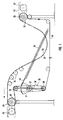
- FIG. 1 shows a device according to the invention which is used in the case of a continuous feed and a discontinuous removal, as is the case, for example, when this device is connected upstream of a strip unwinding device and downstream of a cutting device with a stationary strip.
- the first drive device 26 is synchronized with the continuous conveyor belt 27, the same applies to the second drive device 28, which is synchronized with the discontinuous conveyor belt 29.
- both the first drive 26 and the second drive 28 act directly on the deflection rollers 30, 31.
- the loops 32 of the conveyor belt and 33 of the belt material are formed between the deflection rollers 30, 31, additional guide rollers 34 being provided in the loop area for guidance.
- the loop of both the belt material 33 and the conveyor belt 32 caused by the discontinuous removal at a higher speed than the continuous feed speed changes depending on the operating mode of the discontinuous conveyor belt 29 and thus of the synchronized drive 28. Since here the conveying of the conveyor belt 32 in the direction of Arrow F takes place, the conveyor belt is withdrawn from the belt length storage 35 by the continuous drive 26. Accordingly, the "filling" of the store 35 does not take place continuously, but only when the conveyor belt 43 is fed to the store 35 by the drive 28 at a higher conveying speed.
- the length memory 35 is formed by a lever 36 which can be pivoted substantially centrally about a pivot point 37. At its ends there are rollers 38 around which the conveyor belt 43 is guided.
- the lever 36 is pivotable about its pivot point 37 against the spring force generated by a spring 39, which is articulated at a fixed reference point and engages at the other end on the lever 36 via a chain 40 and a ring gear segment 41 assigned to the lever.
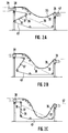
- FIG. 2A shows the initial situation in the event that the belt material 42 is continuously fed and the conveyor belt 43 is continuously driven by the drive 26.
- the conveyor belt 29 and the second drive 28 have just ended their discontinuous conveying and have stopped.
- the length storage 35 was filled, which causes the lever 36 by the dash-dotted spring 39, which was just before the discontinuous conveying started by the continuously removed conveyor belt 43 from the storage 35 in in the Figure 2C shown position brought lever 36 was extremely biased because no tape was fed into the memory, is pivoted by the now occurring tape feed around the pivot point 37 and brought into the position shown in Figure 2A. In this position, the store 35 has its greatest storage capacity, since the deflection path of the conveyor belt 43 is longest in this lever position.
- This device can be assigned sensor elements, not shown, which detect discrepancies with regard to the speed synchronization of the two drives with the respective conveyor belts or positional differences of the individual loops with respect to one another and accordingly control the drives, in particular the second drive 28 accordingly, so that the latter, for example, lifts off the conveyor belt loop Belt material loop operates at a somewhat higher conveying speed than the conveying speed of the belt material, whereby the conveyor belt is pulled away from the belt material until both loops lie flat again on one another. Furthermore, these can be uncoupled and / or braked from their drive connection required for synchronization with the conveyor belt drives, so that when the loop positions are corrected accordingly if necessary, these can be moved independently of their assigned synchronization drive.
Landscapes
- Controlling Rewinding, Feeding, Winding, Or Abnormalities Of Webs (AREA)
- Advancing Webs (AREA)
Applications Claiming Priority (3)
| Application Number | Priority Date | Filing Date | Title |
|---|---|---|---|
| DE4411936 | 1994-04-07 | ||
| DE4411936A DE4411936C2 (de) | 1994-04-07 | 1994-04-07 | Vorrichtung zum Auflagern und Führen eines zu bearbeitenden Bandmaterials im Schlaufenbereich |
| EP95100950A EP0676350B1 (de) | 1994-04-07 | 1995-01-25 | Vorrichtung zum Auflagern und Führen eines zu bearbeitenden Bandmaterials im Schlaufenbereich |
Related Parent Applications (2)
| Application Number | Title | Priority Date | Filing Date |
|---|---|---|---|
| EP95100950A Division EP0676350B1 (de) | 1994-04-07 | 1995-01-25 | Vorrichtung zum Auflagern und Führen eines zu bearbeitenden Bandmaterials im Schlaufenbereich |
| EP95100950.5 Division | 1995-01-25 |
Publications (2)
| Publication Number | Publication Date |
|---|---|
| EP0786427A2 true EP0786427A2 (de) | 1997-07-30 |
| EP0786427A3 EP0786427A3 (enExample) | 1997-08-27 |
Family
ID=6514794
Family Applications (2)
| Application Number | Title | Priority Date | Filing Date |
|---|---|---|---|
| EP97106316A Withdrawn EP0786427A2 (de) | 1994-04-07 | 1995-01-25 | Vorrichtung zum Auflagern und Führen eines zu bearbeitenden Bandmaterials im Schlaufenbereich |
| EP95100950A Expired - Lifetime EP0676350B1 (de) | 1994-04-07 | 1995-01-25 | Vorrichtung zum Auflagern und Führen eines zu bearbeitenden Bandmaterials im Schlaufenbereich |
Family Applications After (1)
| Application Number | Title | Priority Date | Filing Date |
|---|---|---|---|
| EP95100950A Expired - Lifetime EP0676350B1 (de) | 1994-04-07 | 1995-01-25 | Vorrichtung zum Auflagern und Führen eines zu bearbeitenden Bandmaterials im Schlaufenbereich |
Country Status (4)
| Country | Link |
|---|---|
| US (1) | US5617985A (enExample) |
| EP (2) | EP0786427A2 (enExample) |
| JP (1) | JPH07277561A (enExample) |
| DE (2) | DE4411936C2 (enExample) |
Cited By (1)
| Publication number | Priority date | Publication date | Assignee | Title |
|---|---|---|---|---|
| EP0919497A1 (de) * | 1997-12-01 | 1999-06-02 | Karl Eugen Fischer GmbH Maschinenfabrik | Vorrichtung zum Auflagern und Führen eines zu bearbeitenden Materialbandes im Schlaufenbereich |
Families Citing this family (14)
| Publication number | Priority date | Publication date | Assignee | Title |
|---|---|---|---|---|
| US6215205B1 (en) * | 1996-08-06 | 2001-04-10 | The Goodyear Tire & Rubber Company | Adjustable length conveyor system |
| ATE366625T1 (de) | 1997-09-16 | 2007-08-15 | Ishikawajima Harima Heavy Ind | Plattenpressvorrichtung und verfahren |
| US7137283B2 (en) * | 1997-09-16 | 2006-11-21 | Ishikawajima-Harima Heavy Industries Co., Ltd. | Plate reduction press apparatus and methods |
| DE19842585A1 (de) * | 1998-09-17 | 2000-03-23 | Armin Steuer | Speichereinrichtung und ihre Verwendung |
| FR2816264B1 (fr) * | 2000-11-09 | 2003-02-21 | Thomas Bleiner | Dispositif de signalisation visuelle adaptable a un vehicule |
| US6557741B2 (en) * | 2000-12-19 | 2003-05-06 | The Goodyear Tire & Rubber Company | Storage carriage and method of storing a longitudinal component in the storage carriage |
| DE10119440B4 (de) * | 2001-04-20 | 2005-12-08 | Rohde & Schwarz Gmbh & Co. Kg | Verlegevorrichtung für eine Dichtschnur |
| DE10134257B4 (de) * | 2001-07-18 | 2007-04-26 | Cyklop Gmbh | Verpackungsmaschine |
| JP5445876B2 (ja) * | 2012-08-21 | 2014-03-19 | 日高精機株式会社 | 扁平チューブ用フィンの製造装置 |
| DE202013104053U1 (de) | 2012-09-06 | 2013-12-17 | Hi Tech Textile Holding Gmbh | Ausgleichseinrichtung |
| DE102017102468A1 (de) * | 2017-02-08 | 2018-08-09 | TRüTZSCHLER GMBH & CO. KG | Speichertisch für einen Vliesleger und Verfahren zum Betrieb eines Speichertisches |
| CN107265161B (zh) * | 2017-06-09 | 2023-07-07 | 瑞光(上海)电气设备有限公司 | 箱式卫生用品原材料给料系统 |
| CN107500005B (zh) * | 2017-08-21 | 2024-06-18 | 广东方皓金属科技有限公司 | 一种皮带整形输送机 |
| CN115072448A (zh) * | 2022-05-24 | 2022-09-20 | 河北光兴半导体技术有限公司 | 玻璃带输送装置以及输送玻璃带的缓存方法 |
Family Cites Families (11)
| Publication number | Priority date | Publication date | Assignee | Title |
|---|---|---|---|---|
| US2474717A (en) * | 1947-06-21 | 1949-06-28 | Rodney Hunt Machine Co | Process and apparatus for tensionless handling of running lengths of materials |
| US2649867A (en) * | 1949-02-21 | 1953-08-25 | Western Electric Co | Apparatus for advancing filamentary articles |
| DE1154690B (de) * | 1961-11-29 | 1963-09-19 | Guenter Baer Dipl Ing | Vorrichtung zum absatzweisen Bewegen kontinuierlich gefoerderter Materialbahnen |
| US3465936A (en) * | 1966-05-02 | 1969-09-09 | Ampex | Tape tensioning apparatus |
| US3784071A (en) * | 1973-04-02 | 1974-01-08 | Goodyear Tire & Rubber | Variable length festooning of web material |
| AT341477B (de) * | 1973-09-26 | 1978-02-10 | Zimmer Johannes | Verfahren zum transportieren bedruckter warenbahnen |
| US4356946A (en) * | 1977-06-24 | 1982-11-02 | Pako Corporation | Constant conveyor web output velocity compensator for variable input web velocities |
| SU642249A1 (ru) * | 1977-08-08 | 1979-01-15 | Предприятие П/Я А-3404 | Петлевой компенсатор дл непрерывно движущегос материала |
| JPS61197354A (ja) * | 1985-02-27 | 1986-09-01 | Hitachi Ltd | ル−パ装置 |
| JPS63180661A (ja) * | 1987-01-19 | 1988-07-25 | Bridgestone Corp | 帯状材料の搬送装置 |
| JP2830368B2 (ja) * | 1990-05-11 | 1998-12-02 | ソニー株式会社 | 帯状材料の加工システム |
-
1994
- 1994-04-07 DE DE4411936A patent/DE4411936C2/de not_active Expired - Fee Related
-
1995
- 1995-01-25 DE DE59501512T patent/DE59501512D1/de not_active Expired - Fee Related
- 1995-01-25 EP EP97106316A patent/EP0786427A2/de not_active Withdrawn
- 1995-01-25 EP EP95100950A patent/EP0676350B1/de not_active Expired - Lifetime
- 1995-03-22 JP JP7090254A patent/JPH07277561A/ja active Pending
- 1995-04-06 US US08/417,637 patent/US5617985A/en not_active Expired - Fee Related
Cited By (1)
| Publication number | Priority date | Publication date | Assignee | Title |
|---|---|---|---|---|
| EP0919497A1 (de) * | 1997-12-01 | 1999-06-02 | Karl Eugen Fischer GmbH Maschinenfabrik | Vorrichtung zum Auflagern und Führen eines zu bearbeitenden Materialbandes im Schlaufenbereich |
Also Published As
| Publication number | Publication date |
|---|---|
| DE4411936A1 (de) | 1995-10-12 |
| EP0786427A3 (enExample) | 1997-08-27 |
| JPH07277561A (ja) | 1995-10-24 |
| EP0676350A3 (de) | 1996-09-25 |
| DE4411936C2 (de) | 1996-03-28 |
| DE59501512D1 (de) | 1998-04-09 |
| EP0676350A2 (de) | 1995-10-11 |
| EP0676350B1 (de) | 1998-03-04 |
| US5617985A (en) | 1997-04-08 |
Similar Documents
| Publication | Publication Date | Title |
|---|---|---|
| DE69421528T2 (de) | Umwickler mit Kontaktantrieb und Verfahren zur Minimalisierung des Schlupfes zwischen Antriebsrolle und Bahn | |
| AT400327B (de) | Vorrichtung zum beschicken einer vereinzelungseinrichtung für druckprodukte | |
| DE2923947C2 (enExample) | ||
| DE3620593C2 (de) | Vorrichtung zum kontrollierten Zuführen von Folie in einer Verpackungsmaschine | |
| EP0144861B1 (de) | Vorrichtung zum zickzackförmigen Falten und Stapeln von Materialbahnen | |
| EP0786427A2 (de) | Vorrichtung zum Auflagern und Führen eines zu bearbeitenden Bandmaterials im Schlaufenbereich | |
| DE69311674T2 (de) | Verfahren und Vorrichtung zum Überlappen von Plastikbeuletn | |
| DE60113580T2 (de) | Schneidemaschine für eine Vielzahl von Küchen- und/oder Toiletten-Papierrollen | |
| EP0968919B1 (de) | Vorrichtung zum Umwickeln von quaderförmigen Gegenständen mit einem Bahnförmigen Umwickelmaterial | |
| EP3642144B1 (de) | Vorrichtung zur bereitstellung eines spulenförmigen polsterungsprodukts für verpackungszwecke | |
| DE69115823T2 (de) | Apparat zum Hochgeschwindigkeitsstapeln von Papierbögen oder eines kontinuierlichen Bandes mit Abreisstrennung entlang vorperforierter Linien | |
| DE3524246A1 (de) | Verfahren und vorrichtung zum zick-zack-falten endloser materialbahnen | |
| DE3424567A1 (de) | Grossballenpresse | |
| DE1956935C3 (de) | Vorrichtung zum Einziehen von bandförmigem Gut in eine Anlage zum Behandeln dieses Gutes | |
| DE19515506B4 (de) | Einrichtung zum Verarbeiten von Druckereiprodukten | |
| EP3440946A1 (de) | Maschine der tabak verarbeitenden industrie zur gleichzeitigen herstellung mehrerer stränge | |
| DE2902480A1 (de) | Vorrichtung fuer das austauschen sich drehender wickeldorne, auf denen ein band aufgewickelt ist | |
| DE2604729A1 (de) | Verfahren und maschine zur schrumpf- folien-verpackung | |
| EP1836334B1 (de) | Verfahren und vorrichtung zum wickeln eines aus einer mehrzahl von fäden bestehenden bandes auf einen um eine drehachse rotierenden wickelkörper | |
| DE3216399A1 (de) | Vorrichtung zum austauschen eines mit wickelgut bewickelten wickelkerns | |
| DE102011001835A1 (de) | Verfahren und Vorrichtung zur Verarbeitung eines Bandes | |
| EP3737630B1 (de) | Vorrichtung zum schneiden einer materialbahn in einzelne bögen mit einem bahnspeicher | |
| DE1189919B (de) | Foerdereinrichtung aus mehreren hintereinander angeordneten Foerderbaendern | |
| DE102010043063B4 (de) | Vorrichtung und Verfahren zum Puffern einer Mehrzahl von Gütern oder Gutgruppen und Papierhandhabungsanlage mit derselben | |
| DE2123864C2 (de) | Verpackungsmaschine |
Legal Events
| Date | Code | Title | Description |
|---|---|---|---|
| PUAI | Public reference made under article 153(3) epc to a published international application that has entered the european phase |
Free format text: ORIGINAL CODE: 0009012 |
|
| PUAL | Search report despatched |
Free format text: ORIGINAL CODE: 0009013 |
|
| AC | Divisional application: reference to earlier application |
Ref document number: 676350 Country of ref document: EP |
|
| AK | Designated contracting states |
Kind code of ref document: A2 Designated state(s): BE DE FR GB IT NL PT |
|
| AK | Designated contracting states |
Kind code of ref document: A3 Designated state(s): BE DE FR GB IT NL PT |
|
| STAA | Information on the status of an ep patent application or granted ep patent |
Free format text: STATUS: THE APPLICATION IS DEEMED TO BE WITHDRAWN |
|
| 18D | Application deemed to be withdrawn |
Effective date: 19970518 |