EP0786427A2 - Device for supporting and guiding in a loop area a web material to be treated - Google Patents
Device for supporting and guiding in a loop area a web material to be treated Download PDFInfo
- Publication number
- EP0786427A2 EP0786427A2 EP97106316A EP97106316A EP0786427A2 EP 0786427 A2 EP0786427 A2 EP 0786427A2 EP 97106316 A EP97106316 A EP 97106316A EP 97106316 A EP97106316 A EP 97106316A EP 0786427 A2 EP0786427 A2 EP 0786427A2
- Authority
- EP
- European Patent Office
- Prior art keywords
- conveyor belt
- loop
- drive device
- belt
- drive
- Prior art date
- Legal status (The legal status is an assumption and is not a legal conclusion. Google has not performed a legal analysis and makes no representation as to the accuracy of the status listed.)
- Withdrawn
Links
Images
Classifications
-
- B—PERFORMING OPERATIONS; TRANSPORTING
- B65—CONVEYING; PACKING; STORING; HANDLING THIN OR FILAMENTARY MATERIAL
- B65H—HANDLING THIN OR FILAMENTARY MATERIAL, e.g. SHEETS, WEBS, CABLES
- B65H20/00—Advancing webs
- B65H20/06—Advancing webs by friction band
-
- B—PERFORMING OPERATIONS; TRANSPORTING
- B65—CONVEYING; PACKING; STORING; HANDLING THIN OR FILAMENTARY MATERIAL
- B65H—HANDLING THIN OR FILAMENTARY MATERIAL, e.g. SHEETS, WEBS, CABLES
- B65H20/00—Advancing webs
- B65H20/30—Arrangements for accumulating surplus web
- B65H20/32—Arrangements for accumulating surplus web by making loops
-
- B—PERFORMING OPERATIONS; TRANSPORTING
- B65—CONVEYING; PACKING; STORING; HANDLING THIN OR FILAMENTARY MATERIAL
- B65H—HANDLING THIN OR FILAMENTARY MATERIAL, e.g. SHEETS, WEBS, CABLES
- B65H2511/00—Dimensions; Position; Numbers; Identification; Occurrences
- B65H2511/20—Location in space
-
- B—PERFORMING OPERATIONS; TRANSPORTING
- B65—CONVEYING; PACKING; STORING; HANDLING THIN OR FILAMENTARY MATERIAL
- B65H—HANDLING THIN OR FILAMENTARY MATERIAL, e.g. SHEETS, WEBS, CABLES
- B65H2513/00—Dynamic entities; Timing aspects
- B65H2513/10—Speed
-
- B—PERFORMING OPERATIONS; TRANSPORTING
- B65—CONVEYING; PACKING; STORING; HANDLING THIN OR FILAMENTARY MATERIAL
- B65H—HANDLING THIN OR FILAMENTARY MATERIAL, e.g. SHEETS, WEBS, CABLES
- B65H2801/00—Application field
- B65H2801/93—Tyres
Definitions
- the invention relates to a device for supporting and guiding a strip material to be processed, in particular nylon or steel cord strips, in the area of one depending on the continuous or discontinuous supply or removal of the strip material by means of appropriate conveying devices, depending on the discontinuous pull or removal in their hanging Position changing loop of the band material.
- the invention is therefore based on the object of creating a device by means of which a change in the material parameters in the loop area due to the free hanging of the loop can be prevented independently of the changing loop shape.
- the band material in the loop area is at least in the area the loop sink is provided with a supporting conveyor belt that is continuously driven by at least one first drive device and forms a loop, which is speed-coordinated by means of at least one second drive device that locally controls the speed of the conveyor belt via a conveyor belt length memory such that the conveyor belt loop changes synchronously with the material loop and that Belt material loop is supported in every position on the support conveyor belt loop,
- the conveyor belt length storage device consisting of a lever arm which rotates about an axis and is provided with at least two rollers, preferably arranged at its ends, and which guides the support conveyor belt and which, depending on the operating mode of the second drive device, counteracts by conveying the conveyor belt a restoring force from a position with large storage capacity to a position with small Sp Oak capacity is reversibly movable.
- the belt loop therefore does not sag freely due to its support on the support conveyor belt, so that parameter changes due to the weight are excluded. Due to the inventive synchronization of the formation of the conveyor belt loop with that of the material loop, a permanent support is ensured, so that regardless of the operation and the mode of operation of the infeed and outfeed belts and the resulting loop formation, the loop increase or decrease of both loops is always the same.
- the memory can be designed in such a way that it is only an area in which the conveyor belt is placed or folded away with the folding or layering thereof.
- the conveyor belt length storage device consists of a lever arm which can be rotated about an axis and provided with at least two rollers preferably arranged at its ends and which guides the support conveyor belt and which, depending on the operating mode of the second drive device, by conveying the conveyor belt against a restoring force from a position with a large storage capacity into a Position with small storage capacity is reversibly movable.
- This lever which can be reversibly pivoted against a restoring force, enables the conveyor belt to be guided continuously and in a controlled manner even in the store; entanglement or the like of the conveyor belt is not possible here.
- the restoring force which is ultimately also responsible for the tension of the conveyor belt, this can be pre-tensioned accordingly.
- the conveyor belt is automatically re-tensioned in the event of any changes in length.
- the restoring force can, according to the invention, be generated by a spring which engages the lever arm, the axis of which is expediently arranged in the middle of the lever and is counter-mounted at a fixed point, which in a further embodiment of the invention acts on a toothed ring segment arranged on the lever arm via a toothed belt or a chain.
- a sensor element arranged according to the invention to detect speed tolerances between the drive speeds of the first and optionally the second drive device and the respective reference speed and / or to detect differences in position between the belt material and the support conveyor belt, these are determined and the synchronization is adjusted accordingly to compensate for differences.
- the sensor element is in control connection with the first and / or the second drive device for controlling the speed of the respective devices as a function of the detection result, so that automatic readjustment takes place.
- the support conveyor belt can support the belt material in the largest possible loop area
- the support conveyor belt is guided over at least two spaced-apart deflection rollers arranged in the area of the transfer points of the belt material from and to the respective conveyor device, between which the loop runs, the first and / or second drive device drivingly engaging one or both deflection rollers. Due to the close arrangement of the deflection rollers on the respective conveying devices, support is possible in almost the entire loop area. The attack of the drive devices on these deflection rollers according to the invention also ensures safe transport of the conveyor belt in the immediate loop area.
- the first and the second drive devices can preferably engage via a belt or a chain on the deflection roller assigned to the continuously or discontinuously operating conveyor belt, the synchronization then taking place via at least one sensor element which detects the speed of the respective conveyor belt and is in control connection with the respective drive device.
- the belt or chain can be guided both over the deflection roller and the drive device and also a conveyor belt shaft, so that the synchronization takes place directly without sensor elements.
- the drive devices can also be attacked directly on the deflection roller or directly on the support conveyor belt.
- the first drive device is arranged in the area below the deflecting roller, so that the support conveyor belt is withdrawn essentially vertically extending between the deflection roller and the drive device.
- the first and / or the second drive device can be provided with brake and / or clutch devices for braking and / or uncoupling the drive device from the drive connection with the respective deflection roller, so that the drive devices and the deflection rollers if necessary can be driven or braked independently of one another.
- the respective drive device is coupled accordingly can be designed according to the invention as a servo drive, required with the respective deflection roller.
- At least one further guide device for guiding the support conveyor belt inside and / or outside the loop area can be provided in a further embodiment of the invention.
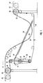
- FIG. 1 shows a device according to the invention which is used in the case of a continuous feed and a discontinuous removal, as is the case, for example, when this device is connected upstream of a strip unwinding device and downstream of a cutting device with a stationary strip.
- the first drive device 26 is synchronized with the continuous conveyor belt 27, the same applies to the second drive device 28, which is synchronized with the discontinuous conveyor belt 29.
- both the first drive 26 and the second drive 28 act directly on the deflection rollers 30, 31.
- the loops 32 of the conveyor belt and 33 of the belt material are formed between the deflection rollers 30, 31, additional guide rollers 34 being provided in the loop area for guidance.
- the loop of both the belt material 33 and the conveyor belt 32 caused by the discontinuous removal at a higher speed than the continuous feed speed changes depending on the operating mode of the discontinuous conveyor belt 29 and thus of the synchronized drive 28. Since here the conveying of the conveyor belt 32 in the direction of Arrow F takes place, the conveyor belt is withdrawn from the belt length storage 35 by the continuous drive 26. Accordingly, the "filling" of the store 35 does not take place continuously, but only when the conveyor belt 43 is fed to the store 35 by the drive 28 at a higher conveying speed.
- the length memory 35 is formed by a lever 36 which can be pivoted substantially centrally about a pivot point 37. At its ends there are rollers 38 around which the conveyor belt 43 is guided.
- the lever 36 is pivotable about its pivot point 37 against the spring force generated by a spring 39, which is articulated at a fixed reference point and engages at the other end on the lever 36 via a chain 40 and a ring gear segment 41 assigned to the lever.
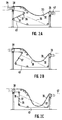
- FIG. 2A shows the initial situation in the event that the belt material 42 is continuously fed and the conveyor belt 43 is continuously driven by the drive 26.
- the conveyor belt 29 and the second drive 28 have just ended their discontinuous conveying and have stopped.
- the length storage 35 was filled, which causes the lever 36 by the dash-dotted spring 39, which was just before the discontinuous conveying started by the continuously removed conveyor belt 43 from the storage 35 in in the Figure 2C shown position brought lever 36 was extremely biased because no tape was fed into the memory, is pivoted by the now occurring tape feed around the pivot point 37 and brought into the position shown in Figure 2A. In this position, the store 35 has its greatest storage capacity, since the deflection path of the conveyor belt 43 is longest in this lever position.
- This device can be assigned sensor elements, not shown, which detect discrepancies with regard to the speed synchronization of the two drives with the respective conveyor belts or positional differences of the individual loops with respect to one another and accordingly control the drives, in particular the second drive 28 accordingly, so that the latter, for example, lifts off the conveyor belt loop Belt material loop operates at a somewhat higher conveying speed than the conveying speed of the belt material, whereby the conveyor belt is pulled away from the belt material until both loops lie flat again on one another. Furthermore, these can be uncoupled and / or braked from their drive connection required for synchronization with the conveyor belt drives, so that when the loop positions are corrected accordingly if necessary, these can be moved independently of their assigned synchronization drive.
Abstract
Description
Die Erfindung betrifft eine Vorrichtung zum Auflagern und Führen eines zu bearbeitenden Bandmateriales, insbesondere von Nylon- oder Stahlcordbändern, im Bereich einer vom kontinuierlichen oder diskontinuierlichen Zu- oder Abtransport des Bandmaterials mittels entsprechender Fördereinrichtungen herrührenden, sich abhängig vom diskontinuierlichen Zug- oder Abtransport in ihrer hängenden Lage ändernden Schlaufe des Bandmaterials.The invention relates to a device for supporting and guiding a strip material to be processed, in particular nylon or steel cord strips, in the area of one depending on the continuous or discontinuous supply or removal of the strip material by means of appropriate conveying devices, depending on the discontinuous pull or removal in their hanging Position changing loop of the band material.
Im Rahmen der Herstellung oder Verarbeitung von derartigen Bandmaterialien kommt es infolge des fördermäßig unterschiedlichen Zu- und Abtransportes des Bandmaterials unweigerlich zur Bildung einer hängenden Schlaufe, die zwischen dem Ende des Zuförderbandes und dem Anfang des Abförderbandes frei durchhängt und infolge der unterschiedlichen Kontinuität der Förderung ihre hängende Lage ändert. Infolge des freien Durchhängens jedoch kommt es infolge des Eigengewichtes des Materials im Schlaufenbereich zu einer Streckung des Materials, was eine Längenänderung zur Folge hat, aufgrund welcher sich zum einen die Materialeigenschaften ändern können, zum anderen können Fehler bei der Bearbeitung von beispielsweise bereits auf eine exakt bestimmte Länge zugeschnittenen Bandteilen auftreten.In the course of the production or processing of such belt materials, due to the different conveying and conveying of the band material, a hanging loop is inevitably formed, which hangs freely between the end of the infeed belt and the beginning of the outfeed belt and, due to the different continuity of the conveying, the hanging loop Location changes. As a result of the free sagging, however, due to the weight of the material in the loop area, the material is stretched, which results in a change in length, on the one hand due to which the material properties can change, and on the other hand, errors in processing can, for example, be precise to one certain length cut band parts occur.
Der Erfindung liegt somit die Aufgabe zugrunde, eine Vorrichtung zu schaffen, mittels welcher eine Veränderung der Materialparameter im Schlaufenbereich bedingt durch das freie Aushängen der Schlaufe unabhängig von der sich ändernden Schlaufenform verhindert werden können.The invention is therefore based on the object of creating a device by means of which a change in the material parameters in the loop area due to the free hanging of the loop can be prevented independently of the changing loop shape.
Zur Lösung dieser Aufgabe ist bei einer Vorrichtung mit den eingangs genannten Merkmalen ein das Bandmaterial im Schlaufenbereich zumindest im Bereich der Schlaufensenke tragendes, von wenigstens einer ersten Antriebseinrichtung kontinuierlich umlaufend angetriebenes und eine Schlaufe bildendes Unterstützungstransportband vorgesehen, das mittels wenigstens einer das Transportband lokal in seiner Geschwindigkeit steuernden zweiten Antriebseinrichtung über einen Transportbandlängenspeicher derart geschwindigkeitskoordiniert wird, daß sich die Transportbandschlaufe synchron mit der Materialschlaufe ändert und die Bandmaterialschlaufe in jeder Lage auf der Unterstützungstransportbandschlaufe aufgelagert ist, wobei der Transportbandlängenspeicher aus einem um eine Achse drehbaren, mit wenigstens zwei vorzugsweise an seine Enden angeordneten Rollen versehenen und das Unterstützungstransportband führenden Hebelarm besteht, der abhängig vom Betriebsmodus der zweiten Antriebseinrichtung durch die Förderung des Transportbands gegen eine Rückstellkraft von einer Stellung mit großer Speicherkapazität in eine Stellung mit kleiner Speicherkapazität reversibel bewegbar ist. Die Bandschlaufe hängt somit infolge ihrer Auflagerung auf dem Unterstützungstransportband nicht frei durch, so daß von der Gewichtskraft bedingte Parameteränderungen ausgeschlossen sind. Durch die erfindungsgemäße Synchronisierung der Formbildung der Transportbandschlaufe mit der der Materialschlaufe ist eine dauernde Auflagerung gewährleistet, so daß unabhängig vom Betrieb und der Betriebsart der Zu- und Abförderbänder und der daraus resultierenden Schlaufenbildung die Schlaufenzu- oder abnahme beider Schlaufen stets gleichlaufend ist.To achieve this object, in a device with the features mentioned at the beginning, the band material in the loop area is at least in the area the loop sink is provided with a supporting conveyor belt that is continuously driven by at least one first drive device and forms a loop, which is speed-coordinated by means of at least one second drive device that locally controls the speed of the conveyor belt via a conveyor belt length memory such that the conveyor belt loop changes synchronously with the material loop and that Belt material loop is supported in every position on the support conveyor belt loop, the conveyor belt length storage device consisting of a lever arm which rotates about an axis and is provided with at least two rollers, preferably arranged at its ends, and which guides the support conveyor belt and which, depending on the operating mode of the second drive device, counteracts by conveying the conveyor belt a restoring force from a position with large storage capacity to a position with small Sp Oak capacity is reversibly movable. The belt loop therefore does not sag freely due to its support on the support conveyor belt, so that parameter changes due to the weight are excluded. Due to the inventive synchronization of the formation of the conveyor belt loop with that of the material loop, a permanent support is ensured, so that regardless of the operation and the mode of operation of the infeed and outfeed belts and the resulting loop formation, the loop increase or decrease of both loops is always the same.
Infolge der sich ändernden Länge der Unterstützungstransportbandschlaufe ist ein Bandspeicher erforderlich, aus welchem bei Schlaufenverlängerung Transportband geschöpft bzw. in welchem bei Schlaufenverkürzung das Transportband abgelegt werden kann. Der Speicher kann dabei derart ausgebildet sein, daß er lediglich ein Bereich ist, in welchem das Transportband unter Faltung bzw. Übereinanderschichtung desselben abgelegt oder entsprechend abgezogen wird. Als Alternativlösung dazu ist jedoch erfindungsgemäß vorgesehen, daß der Transportbandlängenspeicher aus einem um eine Achse drehbaren, mit wenigstens zwei vorzugsweise an seinen Enden angeordneten Rollen versehenen und das Unterstützungstransportband führenden Hebelarm besteht, der abhängig vom Betriebsmodus der zweiten Antriebseinrichtung durch die Förderung des Transportbandes gegen eine Rückstellkraft von einer Stellung mit großer Speicherkapazität in eine Stellung mit kleiner Speicherkapazität reversibel bewegbar ist. Durch diesen, gegen eine Rückstellkraft reversibel schwenkbaren Hebel ist eine dauernde und kontrollierte Führung des Transportbandes selbst im Speicher möglich, ein Verwickeln oder dergleichen des Transportbandes ist hierbei nicht möglich. Darüber hinaus kann durch Einstellung der Rückstellkraft, die letztendlich auch für die Spannung des Transportbandes verantwortlich ist, dieses entsprechend vorgespannt werden, darüber hinaus wird das Transportband bei etwaigen Längenänderungen automatisch nachgespannt.As a result of the changing length of the support conveyor belt loop, a belt store is required from which the conveyor belt can be drawn when the loop is extended or in which the conveyor belt can be stored when the loop is shortened. The memory can be designed in such a way that it is only an area in which the conveyor belt is placed or folded away with the folding or layering thereof. As an alternative solution, however, the invention provides that the conveyor belt length storage device consists of a lever arm which can be rotated about an axis and provided with at least two rollers preferably arranged at its ends and which guides the support conveyor belt and which, depending on the operating mode of the second drive device, by conveying the conveyor belt against a restoring force from a position with a large storage capacity into a Position with small storage capacity is reversibly movable. This lever, which can be reversibly pivoted against a restoring force, enables the conveyor belt to be guided continuously and in a controlled manner even in the store; entanglement or the like of the conveyor belt is not possible here. In addition, by adjusting the restoring force, which is ultimately also responsible for the tension of the conveyor belt, this can be pre-tensioned accordingly. In addition, the conveyor belt is automatically re-tensioned in the event of any changes in length.
Die Rückstellkraft kann erfindungsgemäß von einer am Hebelarm, dessen Achse zweckmäßigerweise in der Hebelmitte angeordnet ist, angreifenden und an einem festen Punkt gegengelagerten Feder erzeugt werden, wobei diese in weiterer Ausgestaltung der Erfindung über eine Zahnriemen oder eine Kette an einem am Hebelarm angeordneten Zahnkranzsegment angreift.The restoring force can, according to the invention, be generated by a spring which engages the lever arm, the axis of which is expediently arranged in the middle of the lever and is counter-mounted at a fixed point, which in a further embodiment of the invention acts on a toothed ring segment arranged on the lever arm via a toothed belt or a chain.
Um die Synchronisation der Schlaufenbildung zu erreichen, ist eine Gleichschaltung der Antriebsgeschwindigkeit der Antriebseinrichtungen des Unterstützungstransportbandes mit den unterschiedlichen Fördergeschwindigkeiten des Bandmaterials erforderlich, weshalb in weiterer Ausgestaltung der Erfindung vorgesehen sein kann, daß die Antriebsgeschwindigkeit der ersten Antriebseinrichtung mit der Fördergeschwindigkeit der kontinuierlich arbeitenden Fördereinrichtung und in Weiterbildung des Erfindungsgedankens, daß die Antriebsgeschwindigkeit der zweiten Antriebseinrichtung mit der Fördergeschwindigkeit der diskontinuierlich arbeitenden Fördereinrichtung des Bandmaterials synchronisiert ist. Durch diese Geschwindigkeitssynchronisation folgt somit die Schlaufenbildung des Transportbandes unweigerlich der von den verschiedenen Fördermodi der Fördereinrichtungen herrührenden Bandmaterialschlaufe. Sollten dennoch Unstimmigkeiten auftreten, die entweder in einem Abheben oder in einem Wellen des Bandmaterials resultieren, kann diesen dadurch begegnet werden, daß über ein erfindungsgemäß angeordnetes Sensorelement zum Ertassen von Geschwindigkeitstoleranzen zwischen den Antriebsgeschwindigkeiten der ersten und gegebenenfalls der zweiten Antriebseinrichtung und der jeweiligen Bezugsgeschwindigkeit und/oder zum Erfassen von Lageunterschieden zwischen dem Bandmaterial und dem Unterstützungstransportband diese festgestellt werden und entsprechend die Synchronisation unterschiedsausgleichend nachgeregelt wird. Dies erfolgt am zweckmäßigsten erfindungsgemäß dadurch, daß das Sensorelement mit der ersten und/oder der zweiten Antriebseinrichtung zur Steuerung der Geschwindigkeit der jeweiligen Einrichtungen in Abhängigkeit des Erfassungsergebnisses in Steuerverbindung steht, so daß eine automatische Nachregelung erfolgt.In order to achieve the synchronization of the loop formation, it is necessary to synchronize the drive speed of the drive devices of the support conveyor belt with the different conveyor speeds of the belt material, which is why it can be provided in a further embodiment of the invention that the drive speed of the first drive device with the conveyor speed of the continuously operating conveyor device and in Development of the inventive concept that the drive speed of the second drive device with the conveying speed of the discontinuously operating conveyor of the strip material is synchronized. As a result of this speed synchronization, the loop formation of the conveyor belt inevitably follows the belt material loop originating from the different conveying modes of the conveying devices. Should there nevertheless be discrepancies which either result in a lifting or in a wave of the strip material, these can be countered by using a sensor element arranged according to the invention to detect speed tolerances between the drive speeds of the first and optionally the second drive device and the respective reference speed and / or to detect differences in position between the belt material and the support conveyor belt, these are determined and the synchronization is adjusted accordingly to compensate for differences. This is most advantageously carried out according to the invention in that the sensor element is in control connection with the first and / or the second drive device for controlling the speed of the respective devices as a function of the detection result, so that automatic readjustment takes place.
Damit das Unterstützungstransportband das Bandmaterial in einem möglichst großen Schlaufenbereich auflagern kann, kann in weiterer Ausgestaltung der Erfindung vorgesehen sein, daß das Unterstützungstransportband über wenigstens zwei im Bereich der Übergabestellen des Bandmaterials von und zu der jeweiligen Fördereinrichtung angeordnete, voneinander beabstandete Umlenkrollen geführt ist, zwischen denen die Schlaufe verläuft, wobei die erste und/oder zweite Antriebseinrichtung an einer oder beiden Umlenkrollen, diese treibend angreifen. Durch die nahe Anordnung der Umlenkrollen an den jeweiligen Fördereinrichtungen ist somit eine Auflagerung fast im gesamten Schlaufenbereich möglich. Durch den erfindungsgemäßen Angriff der Antriebseinrichtungen an diesen Umlenkrollen wird ferner ein sicherer Transport des Transportbandes im unmittelbaren Schlaufenbereich gewährleistet. Erfindungsgemäß können die erste und die zweite Antriebseinrichtungen vorzugsweise über einen Riemen oder eine Kette an der dem kontinuierlich bzw. diskontinuierlich arbeitenden Förderband zugeordneten Umlenkrolle angreifen, wobei die Synchronisierung dann über wenigstens ein die Geschwindigkeit des jeweiligen Förderbandes erfassendes und mit der jeweiligen Antriebseinrichtung in Steuerverbindung stehendes Sensorelement erfolgt. Ferner kann der Riemen bzw. die Kette sowohl über die Umlenkrolle und die Antriebseinrichtung als auch eine Förderbandwelle geführt sein, so daß die Synchronisierung direkt ohne Sensorelemente erfolgt. Alternativ dazu kann der Angriff der Antriebseinrichtungen auch direkt an der Umlenkrolle oder direkt am Unterstützungstransportband erfolgen. Um im letzteren Fall, der insbesondere bezüglich der ersten Antriebseinrichtung realisierbar ist, einen exakten und kontinuierlichen Abzug des Bandes gewährleisten zu können, kann in weiterer Ausgestaltung der Erfindung vorgesehen sein, daß die erste Antriebseinrichtung im Bereich unterhalb der Umlenkrolle angeordnet ist, so daß das Unterstützungstransportband im wesentlichen vertikal verlaufend zwischen der Umlenkrolle und der Antriebseinrichtung abgezogen wird.In order that the support conveyor belt can support the belt material in the largest possible loop area, it can be provided in a further embodiment of the invention that the support conveyor belt is guided over at least two spaced-apart deflection rollers arranged in the area of the transfer points of the belt material from and to the respective conveyor device, between which the loop runs, the first and / or second drive device drivingly engaging one or both deflection rollers. Due to the close arrangement of the deflection rollers on the respective conveying devices, support is possible in almost the entire loop area. The attack of the drive devices on these deflection rollers according to the invention also ensures safe transport of the conveyor belt in the immediate loop area. According to the invention, the first and the second drive devices can preferably engage via a belt or a chain on the deflection roller assigned to the continuously or discontinuously operating conveyor belt, the synchronization then taking place via at least one sensor element which detects the speed of the respective conveyor belt and is in control connection with the respective drive device. Furthermore, the belt or chain can be guided both over the deflection roller and the drive device and also a conveyor belt shaft, so that the synchronization takes place directly without sensor elements. Alternatively, the drive devices can also be attacked directly on the deflection roller or directly on the support conveyor belt. In order to be able to ensure an exact and continuous removal of the belt in the latter case, which can be implemented in particular with respect to the first drive device, it can be provided in a further embodiment of the invention that the first drive device is arranged in the area below the deflecting roller, so that the support conveyor belt is withdrawn essentially vertically extending between the deflection roller and the drive device.
Der Ausgleich etwaiger Lagerunterschiede der einzelnen Bänder erfolgt, wie bereits beschrieben, durch entsprechende Nachregelung der Antriebsgeschwindigkeiten der verschiedenen Antriebseinrichtungen des Unterstützungstransportbandes, das dann entsprechend des Unterschiedes verlangsamt oder schneller gefördert und quasi unter dem Bandmaterial durchgezogen wird, bis beide Bänder wieder aufeinanderliegen. Damit dieses Durchziehen möglich ist, können erfindungsgemäß die erste und/oder die zweite Antriebseinrichtung mit Brems- und/oder Kupplungseinrichtungen zum Bremsen und/oder Entkuppeln der Antriebseinrichtung aus der Antriebsverbindung mit der jeweiligen Umlenkrolle versehen sein, so daß im Bedarfsfall die Antriebseinrichtungen und die Umlenkrollen unabhängig voneinander antreib- oder bremsbar sind. Dies ist jedoch nur bei entsprechender Kopplung der jeweiligen Antriebseinrichtung, die erfindungsgemäß als ein Servoantrieb ausgebildet sein kann, mit der jeweiligen Umlenkrolle erforderlich.As already described, any differences in storage of the individual belts are compensated for by corresponding readjustment of the drive speeds of the various drive devices of the support conveyor belt, which is then slowed down or conveyed faster according to the difference and is quasi pulled through under the belt material until the two belts rest on one another again. So that this pulling through is possible, according to the invention the first and / or the second drive device can be provided with brake and / or clutch devices for braking and / or uncoupling the drive device from the drive connection with the respective deflection roller, so that the drive devices and the deflection rollers if necessary can be driven or braked independently of one another. However, this is only possible if the respective drive device is coupled accordingly can be designed according to the invention as a servo drive, required with the respective deflection roller.
Damit das Unterstützungstransportband sowohl innerhalb als auch außerhalb des Schlaufenbereiches nicht unkontrolliert gefördert wird, kann in weiterer Ausgestaltung der Erfindung wenigstens eine weitere Führungseinrichtung, insbesondere Rollen, zur Führung des Unterstützungstransportbandes innerhalb und/oder außerhalb des Schlaufenbereiches vorgesehen sein.In order that the support conveyor belt is not conveyed in an uncontrolled manner both inside and outside the loop area, at least one further guide device, in particular rollers, for guiding the support conveyor belt inside and / or outside the loop area can be provided in a further embodiment of the invention.
Weitere Vorteile, Merkmale und Einzelheiten der Erfindung ergeben sich aus den im folgenden beschriebenen Ausführungsbeispielen sowie anhand der Zeichnungen. Dabei zeigen:
- Fig. 1
- eine erfindungsgemäße Vorrichtung zum Auflagern der Schlaufe eines Bandmaterials bei kontinuierlicher Zu- und diskontinuierlicher Abförderung, und
- Fig. 2A, 2B, 2C
- die Vorrichtung aus Fig. 1 in schematisierter Form in verschiedenen Schlaufenstellungen.
- Fig. 1
- an inventive device for supporting the loop of a strip material with continuous feeding and discontinuous removal, and
- 2A, 2B, 2C
- the device of FIG. 1 in a schematic form in different loop positions.
Figur 1 zeigt eine erfindungsgemäße Vorrichtung, die im Falle eines kontinuierlichen Antransports und eines diskontinuierlichen Abtransport zum Einsatz kommt, wie dies beispielsweise dann der Fall ist, wenn diese Vorrichtung einer Bandabwicklungsvorrichtung vorgeschaltet und einer Schneidvorrichtung mit ruhendem Band nachgeschaltet ist. Hier ist die erste Antriebsvorrichtung 26 mit dem kontinuierlichen Förderband 27 synchronisiert, gleiches gilt für die zweite Antriebseinrichtung 28, die mit dem diskontinuierlichen Förderband 29 synchronisiert ist. Im gezeigten Ausführungsbeispiel greifen sowohl der erste Antrieb 26 als auch der zweite Antrieb 28 direkt an den Umlenkrollen 30, 31 an.FIG. 1 shows a device according to the invention which is used in the case of a continuous feed and a discontinuous removal, as is the case, for example, when this device is connected upstream of a strip unwinding device and downstream of a cutting device with a stationary strip. Here, the
Zwischen den Umlenkrollen 30, 31 bilden sich die Schlaufen 32 des Transportbandes und 33 des Bandmaterials, wobei zur Führung noch zusätzliche Führungsrollen 34 im Schlaufenbereich vorgesehen sind. Hier ändert sich die durch die diskontinuierliche Abfuhr mit höherer Geschwindigkeit als die kontinuierliche Zufuhrgeschwindigkeit verursachte Schlaufe sowohl des Bandmaterials 33 als auch des Transportbandes 32 abhängig vom Betriebsmodus des diskontinuierlichen Förderbandes 29 und damit des synchronisierten Antriebs 28. Da hier die Förderung des Transportbandes 32 in Richtung des Pfeiles F erfolgt, wird Transportband von dem kontinuierlichen Antrieb 26 aus dem Bandlängenspeicher 35 abgezogen. Die "Füllung" des Speichers 35 erfolgt demzufolge nicht kontinuierlich, sondern erst dann, wenn das Transportband 43 vom Antrieb 28 mit höherer Fördergeschwindigkeit dem Speicher 35 zugeführt wird. Der Längenspeicher 35 wird bei dieser Ausführungsform von einem Hebel 36 gebildet, der im wesentlichen mittig um einen Drehpunkt 37 verschwenkbar ist. An seinen Enden sind Rollen 38 angeordnet, um welche das Transportband 43 geführt ist. Der Hebel 36 ist um seinen Drehpunkt 37 gegen die von einer Feder 39, die an einem festen Bezugspunkt angelenkt und am anderen Ende am Hebel 36 über eine Kette 40 und ein dem Hebel zugeordnetes Zahnkranzsegment 41 angreift, erzeugte Federkraft verschwenkbar.The
Die Funktion des Längenspeichers wird anhand der Figuren 2A bis C deutlich. Figur 2A stellt die Ausgangssituation für den Fall dar, daß das Bandmaterial 42 kontinuierlich angefördert und das Transportband 43 über den Antrieb 26 kontinuierlich umgetrieben wird. Das Förderband 29 und der zweite Antrieb 28 haben gerade ihre diskontinuierliche Förderung beendet und sind gestoppt. Infolge der gegenüber der kontinuierlichen Zuführgeschwindigkeit erhöhten diskontinuierlichen Fördergeschwindigkeit wurde der Längenspeicher 35 aufgefüllt, was bewirkt, daß der Hebel 36 von der strichpunktiert dargestellten Feder 39, die zuvor kurz vor Einsetzen der diskontinuierlichen Förderung von dem durch das kontinuierlich abgezogene Transportband 43 aus dem Speicher 35 in die in Figur 2C gezeigte Stellung gebrachten Hebel 36 extrem vorgespannt war, da keine Bandzufuhr in den Speicher erfolgte, durch die nunmehr stattfindende Bandzufuhr um den Drehpunkt 37 herumgeschwenkt und in die in Figur 2A gezeigte Position gebracht wird. In dieser Position besitzt der Speicher 35 seine größte Speicherkapazität, da der Umlenkweg des Transportbandes 43 in dieser Hebelstellung am längsten ist.The function of the length memory is clear from FIGS. 2A to C. FIG. 2A shows the initial situation in the event that the
Durch den kontinuierlichen Abzug des Förderbandes 43 aus dem Speicher 35 mittels des kontinuierlichen Antriebs 26 wird nun der Hebel 36, da keine Zufuhr in den Speicher 35 erfolgt, wieder um den Drehpunkt 37 gegen die Feder 39 verschwenkt, wodurch diese vorgespannt wird. Dies ist Figur 2B zu entnehmen. Die Schwenkbewegung setzt sich solange fort, bis der diskontinuierliche Abtransport wieder stattfindet und der Speicher 35 infolge der schnellen Abfördergeschwindigkeit wieder aufgefüllt wird, was bewirkt, das der Hebel 36 wieder von der sich entspannenden Feder 39 in die in Figur 2A gezeigte Stellung überführt wird. Nach erfolgtem Stopp des Materialabzuges beginnt der Kreislauf von neuem.Due to the continuous removal of the
Dieser Vorrichtung können nicht dargestellte Sensorelemente zugeordnet sein, die Unstimmigkeiten hinsichtlich der Geschwindigkeitssynchronisation beider Antriebe mit den jeweiligen Förderbändern oder Lagedifferenzen der einzelnen Schlaufen zueinander erfassen und entsprechend die Antriebe, insbesondere den zweiten Antrieb 28 entsprechend steuern, so daß dieser beispielsweise bei sich von der Transportbandschlaufe abhebender Bandmaterialschlaufe mit etwas erhöhter Fördergeschwindigkeit als die Abfördergeschwindigkeit des Bandmaterials arbeitet, wodurch das Transportband unter dem Bandmaterial solange weggezogen wird, bis beide Schlaufen wieder flächig aufeinanderliegen. Ferner können diese aus ihrer zur Synchronisation erforderlichen Antriebsverbindung mit den Förderbandantrieben entkuppelbar und/oder bremsbar sein, so daß bei entsprechend erforderlicher Korrektur der Schlaufenlagen diese notfalls unabhängig von ihrem zugeordneten Synchronisationsantrieb bewegt werden können.This device can be assigned sensor elements, not shown, which detect discrepancies with regard to the speed synchronization of the two drives with the respective conveyor belts or positional differences of the individual loops with respect to one another and accordingly control the drives, in particular the
Claims (17)
Applications Claiming Priority (3)
| Application Number | Priority Date | Filing Date | Title |
|---|---|---|---|
| DE4411936 | 1994-04-07 | ||
| DE4411936A DE4411936C2 (en) | 1994-04-07 | 1994-04-07 | Device for supporting and guiding a strip material to be processed in the loop area |
| EP95100950A EP0676350B1 (en) | 1994-04-07 | 1995-01-25 | Device for supporting and guiding in a loop area a web material to be treated |
Related Parent Applications (2)
| Application Number | Title | Priority Date | Filing Date |
|---|---|---|---|
| EP95100950A Division EP0676350B1 (en) | 1994-04-07 | 1995-01-25 | Device for supporting and guiding in a loop area a web material to be treated |
| EP95100950.5 Division | 1995-01-25 |
Publications (2)
| Publication Number | Publication Date |
|---|---|
| EP0786427A2 true EP0786427A2 (en) | 1997-07-30 |
| EP0786427A3 EP0786427A3 (en) | 1997-08-27 |
Family
ID=6514794
Family Applications (2)
| Application Number | Title | Priority Date | Filing Date |
|---|---|---|---|
| EP97106316A Withdrawn EP0786427A2 (en) | 1994-04-07 | 1995-01-25 | Device for supporting and guiding in a loop area a web material to be treated |
| EP95100950A Expired - Lifetime EP0676350B1 (en) | 1994-04-07 | 1995-01-25 | Device for supporting and guiding in a loop area a web material to be treated |
Family Applications After (1)
| Application Number | Title | Priority Date | Filing Date |
|---|---|---|---|
| EP95100950A Expired - Lifetime EP0676350B1 (en) | 1994-04-07 | 1995-01-25 | Device for supporting and guiding in a loop area a web material to be treated |
Country Status (4)
| Country | Link |
|---|---|
| US (1) | US5617985A (en) |
| EP (2) | EP0786427A2 (en) |
| JP (1) | JPH07277561A (en) |
| DE (2) | DE4411936C2 (en) |
Cited By (1)
| Publication number | Priority date | Publication date | Assignee | Title |
|---|---|---|---|---|
| EP0919497A1 (en) * | 1997-12-01 | 1999-06-02 | Karl Eugen Fischer GmbH Maschinenfabrik | Device for supporting and guiding a material web to be treated in the loop area |
Families Citing this family (13)
| Publication number | Priority date | Publication date | Assignee | Title |
|---|---|---|---|---|
| US6215205B1 (en) * | 1996-08-06 | 2001-04-10 | The Goodyear Tire & Rubber Company | Adjustable length conveyor system |
| ATE346699T1 (en) | 1997-09-16 | 2006-12-15 | Ishikawajima Harima Heavy Ind | PLATE PRESSING APPARATUS AND METHOD |
| US7137283B2 (en) * | 1997-10-14 | 2006-11-21 | Ishikawajima-Harima Heavy Industries Co., Ltd. | Plate reduction press apparatus and methods |
| DE19842585A1 (en) * | 1998-09-17 | 2000-03-23 | Armin Steuer | Storage device and its use |
| FR2816264B1 (en) * | 2000-11-09 | 2003-02-21 | Thomas Bleiner | VISUAL SIGNALING DEVICE ADAPTABLE TO A VEHICLE |
| US6557741B2 (en) * | 2000-12-19 | 2003-05-06 | The Goodyear Tire & Rubber Company | Storage carriage and method of storing a longitudinal component in the storage carriage |
| DE10119440B4 (en) * | 2001-04-20 | 2005-12-08 | Rohde & Schwarz Gmbh & Co. Kg | Installation device for a sealing cord |
| DE10134257B4 (en) * | 2001-07-18 | 2007-04-26 | Cyklop Gmbh | packaging machine |
| JP5445876B2 (en) * | 2012-08-21 | 2014-03-19 | 日高精機株式会社 | Flat tube fin manufacturing equipment |
| US9617104B2 (en) | 2012-09-06 | 2017-04-11 | Hi Tech Textile Holding Gmbh | Compensating device for fluctuating conveying speeds of a fibrous nonwoven |
| DE102017102468A1 (en) * | 2017-02-08 | 2018-08-09 | TRüTZSCHLER GMBH & CO. KG | Storage table for a nonwoven layer and method for operating a storage table |
| CN107265161B (en) * | 2017-06-09 | 2023-07-07 | 瑞光(上海)电气设备有限公司 | Box-type sanitary product raw material feeding system |
| CN107500005A (en) * | 2017-08-21 | 2017-12-22 | 东莞方皓汽车配件有限公司 | A kind of belt shaping conveyer |
Citations (3)
| Publication number | Priority date | Publication date | Assignee | Title |
|---|---|---|---|---|
| DE1154690B (en) * | 1961-11-29 | 1963-09-19 | Guenter Baer Dipl Ing | Device for the stepwise movement of continuously conveyed material webs |
| JPS61197354A (en) * | 1985-02-27 | 1986-09-01 | Hitachi Ltd | Looper apparatus |
| JPH0420451A (en) * | 1990-05-11 | 1992-01-24 | Sony Corp | Processing system for a band-shaped material |
Family Cites Families (8)
| Publication number | Priority date | Publication date | Assignee | Title |
|---|---|---|---|---|
| US2474717A (en) * | 1947-06-21 | 1949-06-28 | Rodney Hunt Machine Co | Process and apparatus for tensionless handling of running lengths of materials |
| US2649867A (en) * | 1949-02-21 | 1953-08-25 | Western Electric Co | Apparatus for advancing filamentary articles |
| US3465936A (en) * | 1966-05-02 | 1969-09-09 | Ampex | Tape tensioning apparatus |
| US3784071A (en) * | 1973-04-02 | 1974-01-08 | Goodyear Tire & Rubber | Variable length festooning of web material |
| AT341477B (en) * | 1973-09-26 | 1978-02-10 | Zimmer Johannes | METHOD OF TRANSPORTING PRINTED TRACKS |
| US4356946A (en) * | 1977-06-24 | 1982-11-02 | Pako Corporation | Constant conveyor web output velocity compensator for variable input web velocities |
| SU642249A1 (en) * | 1977-08-08 | 1979-01-15 | Предприятие П/Я А-3404 | Loop-type compensator for continuously moving material |
| JPS63180661A (en) * | 1987-01-19 | 1988-07-25 | Bridgestone Corp | Transport device for strip-shaped material |
-
1994
- 1994-04-07 DE DE4411936A patent/DE4411936C2/en not_active Expired - Fee Related
-
1995
- 1995-01-25 EP EP97106316A patent/EP0786427A2/en not_active Withdrawn
- 1995-01-25 EP EP95100950A patent/EP0676350B1/en not_active Expired - Lifetime
- 1995-01-25 DE DE59501512T patent/DE59501512D1/en not_active Expired - Fee Related
- 1995-03-22 JP JP7090254A patent/JPH07277561A/en active Pending
- 1995-04-06 US US08/417,637 patent/US5617985A/en not_active Expired - Fee Related
Patent Citations (3)
| Publication number | Priority date | Publication date | Assignee | Title |
|---|---|---|---|---|
| DE1154690B (en) * | 1961-11-29 | 1963-09-19 | Guenter Baer Dipl Ing | Device for the stepwise movement of continuously conveyed material webs |
| JPS61197354A (en) * | 1985-02-27 | 1986-09-01 | Hitachi Ltd | Looper apparatus |
| JPH0420451A (en) * | 1990-05-11 | 1992-01-24 | Sony Corp | Processing system for a band-shaped material |
Non-Patent Citations (3)
| Title |
|---|
| PATENT ABSTRACTS OF JAPAN vol. 11, no. 25 (M-556) [2472] , 23.Januar 1987 & JP 61 197354 A (HITACHI), 1.September 1986, * |
| PATENT ABSTRACTS OF JAPAN vol. 16, no. 181 (M-1242), 30.April 1992 & JP 04 020451 A (SONY), 24.Januar 1992, * |
| SOVIET INVENTIONS ILLUSTRATED Section Ch, Week 41 21.November 1979 Derwent Publications Ltd., London, GB; Class A35, AN 74837B XP002008400 & SU 642 249 A (PETRAKOV YU A) , 15.Januar 1979 * |
Cited By (1)
| Publication number | Priority date | Publication date | Assignee | Title |
|---|---|---|---|---|
| EP0919497A1 (en) * | 1997-12-01 | 1999-06-02 | Karl Eugen Fischer GmbH Maschinenfabrik | Device for supporting and guiding a material web to be treated in the loop area |
Also Published As
| Publication number | Publication date |
|---|---|
| JPH07277561A (en) | 1995-10-24 |
| EP0676350A2 (en) | 1995-10-11 |
| EP0676350B1 (en) | 1998-03-04 |
| US5617985A (en) | 1997-04-08 |
| DE59501512D1 (en) | 1998-04-09 |
| DE4411936A1 (en) | 1995-10-12 |
| DE4411936C2 (en) | 1996-03-28 |
| EP0676350A3 (en) | 1996-09-25 |
| EP0786427A3 (en) | 1997-08-27 |
Similar Documents
| Publication | Publication Date | Title |
|---|---|---|
| AT400327B (en) | DEVICE FOR FEEDING A SEALING DEVICE FOR PRINTED PRODUCTS | |
| DE2923947C2 (en) | ||
| DE3620593C2 (en) | Device for the controlled feeding of film in a packaging machine | |
| EP0144861B1 (en) | Machine for the zig-zag folding and stacking of webs | |
| DE60113580T2 (en) | Cutting machine for a variety of kitchen and / or toilet paper rolls | |
| EP0786427A2 (en) | Device for supporting and guiding in a loop area a web material to be treated | |
| EP3642144B1 (en) | Apparatus for supplying a coil-like padding product for packaging purposes | |
| EP1836334B1 (en) | Method and device for winding a ribbon comprised of a number of threads onto a winding body rotating about a rotation axis | |
| EP0968919B1 (en) | Method and device for enveloping quadrangular objects with a tape-like enveloping material | |
| DE3524246A1 (en) | METHOD AND DEVICE FOR ZIGZAG FOLDING ENDLESS MATERIALS | |
| DE3424567A1 (en) | BIG PRESS | |
| DE1956935C3 (en) | Device for drawing in strip-shaped material in a system for treating this material | |
| DE19515506B4 (en) | Device for processing printed products | |
| DE2902480A1 (en) | DEVICE FOR REPLACING ROTATING SPINDLE MACHINES ON WHICH A TAPE IS COILED | |
| DE2604729A1 (en) | PROCESS AND MACHINE FOR SHRINK FILM PACKAGING | |
| EP3440946A1 (en) | Machine for the tobacco processing industry for simultaneously producing a number of strands | |
| DE102011001835A1 (en) | Method and device for processing a strip | |
| DE3216399A1 (en) | DEVICE FOR REPLACING A WINDING CORE Wrapped With Wrapped Material | |
| DE1189919B (en) | Conveying device made up of several conveyor belts arranged one behind the other | |
| DE102010043063B4 (en) | Apparatus and method for buffering a plurality of goods or crop groups and paper handling equipment therewith | |
| EP3737630B1 (en) | Apparatus for cutting a material web into individual sheets having a web store | |
| DE2123864C2 (en) | Packing machine | |
| DE2111160B2 (en) | DEVICE FOR FEEDING METALLIZED STRIPS IN A PLATE PRESS PROCESSING FILM MATERIAL | |
| DE2062859A1 (en) | Device for conveying band-like structures by means of rollers, in particular on weaving machines | |
| EP1431454B1 (en) | Web treating device |
Legal Events
| Date | Code | Title | Description |
|---|---|---|---|
| PUAI | Public reference made under article 153(3) epc to a published international application that has entered the european phase |
Free format text: ORIGINAL CODE: 0009012 |
|
| PUAL | Search report despatched |
Free format text: ORIGINAL CODE: 0009013 |
|
| AC | Divisional application: reference to earlier application |
Ref document number: 676350 Country of ref document: EP |
|
| AK | Designated contracting states |
Kind code of ref document: A2 Designated state(s): BE DE FR GB IT NL PT |
|
| AK | Designated contracting states |
Kind code of ref document: A3 Designated state(s): BE DE FR GB IT NL PT |
|
| STAA | Information on the status of an ep patent application or granted ep patent |
Free format text: STATUS: THE APPLICATION IS DEEMED TO BE WITHDRAWN |
|
| 18D | Application deemed to be withdrawn |
Effective date: 19970518 |