EP0968919B1 - Method and device for enveloping quadrangular objects with a tape-like enveloping material - Google Patents
Method and device for enveloping quadrangular objects with a tape-like enveloping material Download PDFInfo
- Publication number
- EP0968919B1 EP0968919B1 EP99111011A EP99111011A EP0968919B1 EP 0968919 B1 EP0968919 B1 EP 0968919B1 EP 99111011 A EP99111011 A EP 99111011A EP 99111011 A EP99111011 A EP 99111011A EP 0968919 B1 EP0968919 B1 EP 0968919B1
- Authority
- EP
- European Patent Office
- Prior art keywords
- web
- article
- arrangement
- material web
- wrapped
- Prior art date
- Legal status (The legal status is an assumption and is not a legal conclusion. Google has not performed a legal analysis and makes no representation as to the accuracy of the status listed.)
- Expired - Lifetime
Links
Images
Classifications
-
- B—PERFORMING OPERATIONS; TRANSPORTING
- B65—CONVEYING; PACKING; STORING; HANDLING THIN OR FILAMENTARY MATERIAL
- B65B—MACHINES, APPARATUS OR DEVICES FOR, OR METHODS OF, PACKAGING ARTICLES OR MATERIALS; UNPACKING
- B65B11/00—Wrapping, e.g. partially or wholly enclosing, articles or quantities of material, in strips, sheets or blanks, of flexible material
- B65B11/06—Wrapping articles, or quantities of material, by conveying wrapper and contents in common defined paths
- B65B11/08—Wrapping articles, or quantities of material, by conveying wrapper and contents in common defined paths in a single straight path
- B65B11/10—Wrapping articles, or quantities of material, by conveying wrapper and contents in common defined paths in a single straight path to fold the wrappers in tubular form about contents
Definitions
- the present invention relates to a device for wrapping cuboid objects with a web-shaped wrapping material according to the preamble of claim 1.
- a device of this type is known from EP-A-0 120 251 and the corresponding one U.S. Patent No. 4,738,078.
- a leadership facility guides the material web, forming a material web loop along the rear side of the Subject and simultaneously forms a first material web section and on the other hand one on the rear side of the object extending second material web section, the length of which is greater than the dimension of the object in the longitudinal direction of this second Material web section.
- the tensioned material web sections are held by means of holding arrangements that have needles that the Pierce the web of material.
- the material web is then by means of a stationary cutting device between the two holding arrangements severed.
- the object When rotating the pad, the object is only by its own weight and the tensioned and held second material web section held. On the one hand, this requires a certain material web Strength and on the other hand, in order to enable a quick turning, the arranging the object at least approximately centrally on the support table, so that its axis of rotation is at least approximated by the The focus of the subject is.
- the wrapped object is also during the rotation of the table kept compressed between this and the printing device, which, on the one hand, leads to a rich concern for the material web on Object leads and on the other hand a very fast rotation of the pad allows even if the object is eccentric with respect to the axis of rotation is arranged.
- the material web must continue when turning the pad no longer assume holding forces for the object.
- the support table two spaced apart and independent printing devices controlled from each other at a distance from the support table assigned. This allows the introduction of another one too wrapping object between the support table and one of the Printing facilities, while another already wrapped, between object arranged on the support table and the other printing device is conveyed away from the support table. You can use these items have different dimensions.
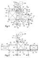
- the device shown in the figures for wrapping cuboid Objects 10, 10 'with a web-shaped wrapping material 12, has a conveyor 14 with three series-connected belt conveyors 16, 18 and 20 on. These define a movement path 22 for the objects 10, 10 'to be wrapped.
- the middle belt conveyor 18 of the three belt conveyors forms a support table 24, which is arranged around a center, in the vertical direction and at right angles to the trajectory 22 axis 26 is rotatable.
- On schematically indicated rotary drive 28 is intended to support the table 24 each by 180 °.
- Each of these printing devices 30, 32 has one in the vertical direction extending, attached to the frame part guide rail 34 on the an endless printing belt 38 guided around rollers 36 by means of a schematic indicated drive 40 is mounted adjustable in height.
- the two Printing tapes 38 of the printing devices 30, 32 are individual in their Height and thus adjustable in its distance from the second belt conveyor 18, but reversibly driven synchronously with the second belt conveyor 18.
- Each of the printing devices 30, 32 forms with the second belt conveyor 18 a folding channel 42 for U-shaped folding of the wrapping material 12 around the object to be wrapped 10.
- the in the longitudinal direction of the second belt conveyor 18 measured length of the printing devices 30, 32 is less than the length of the second belt conveyor 18 minus that in Length of the second belt conveyor 18 measured length of largest object to be wrapped 10. Further is the regarding Axle 26 in the radial direction of the roller 36 located vertically above the associated deflection roller 44 of the second belt conveyor 18.
- the support table 24 has both ends and below the second Belt conveyor 18 a holding device designed as a vacuum bar 46 48 on.
- the distance between the first belt conveyor 16 and the second belt conveyor 18 on the one hand and this and the third belt conveyor 20 on the other is as small as possible but chosen such that the second belt conveyor 18 can be rotated about the axis 26.
- first belt conveyor 16 located first belt conveyor 16 is another printing device 50 assigned.
- This has a further vertical guide rail 52 further pressure band adjustable in height by means of a drive 40 ' 54, which is guided around further rollers 56.
- This other print ribbon 54 and the first belt conveyor 16 form for each to be wrapped Item 10 a press channel 58.
- a vacuum bar 46 trained further holding device 48 'arranged stationary.
- a dash-dotted line runs through it in the vertical direction V. Path of movement 60 of a guide device 62.
- the two side by side Deflection rollers 64 having a parallel-axis guide device 62 is of a rest position 66 shown in FIG located above the highest position of the printing tapes 38, 54 in vertical direction downwards, in a separation position shown in FIG. 7 66 'and movable back again.
- the separation position 66 ' is located below the holding devices 48 and 48 '.
- the web-shaped wrapping material 12 is from one above the conveyor 14 and the printing devices 30, 32, 50 arranged supply roll 68 deducted.
- the material web runs from the supply roll 68 70, forming supply loops around a plurality of stationary rollers 72 and in between arranged dancer rollers 74.
- the free end of the material web 70 runs with a first material web section 76, the movement path 22 of the object 10 to be wrapped crossing between the first and second belt conveyor 16, 18, and is at the free end region held by the stationary holding device 48 '.
- the objects to be wrapped are 10, 10 'around stacks of different heights of printed matter, such as newspapers, magazines or the like.
- wrapping material 12 is a self-adhesive plastic film.
- the first Belt conveyor 16 facing printing device 30 of the support table 24 is at the level of the further printing device 50 by means of the drive 40 set.
- the guide device 62 moved from its rest position 66 into the separation position 66 '.
- the material web 70 becomes a material web loop 80 along the rear side 82 of the object as seen in the conveying direction F. 10 to below the conveyor 14 and the corresponding Holding devices 48, 48 'passed through; see also FIG. 3.
- FIG. 7 shows the separation position 66 'of the guide device 62.
- the material web 70 was vacuumed on both applied vacuum bar 46, whereby the material web 70th is captured.
- a schematically indicated machine frame 84 on which in a manner not shown but generally known the other parts of the device are arranged is a U-shaped in cross section Support element 86 attached. Between the leg ends of the support element 86 and the deflection rollers 64 of the guide device 62 the web of material 70 is clamped.
- the guide device 62 has a cutting knife 88 which consists of a 6 retracted position shown approximately at the level of the axes of the Deflection rollers 64 in a downward direction into one shown in FIG. 7 Cutting position over the lower tangent to the two deflecting rollers 64 is slidable through it. With this movement, the clamped Material web 70 in the first material web section 76 and a second Material web section 90 separated with the end section 78.
- the vacuum bars 46 have one hollow, cross-sectionally rectangular beams, whose interior with a schematically indicated vacuum source 92 is connected, and the side of the material web 70 facing a plurality of Through holes is provided.
- the input side of the first belt conveyor 16 is another in FIG. 2 Object 10 ", on which a cover sheet lies, is shown.
- the further printing device 50 is at a distance from the first belt conveyor 16 on a Height shifted slightly higher than the corresponding one Dimension of the object 10 ''.
- This object 10 is, as shown in FIG. 3, in the press channel 58 introduced and pressed together by lowering the further pressure device 50.
- the guide means 62 is in the separation position 66 'shown in FIG. 7 and that Cutting knife 88 cuts the material web 70. It got further Printing belt 38 of the printing device 32 simultaneously with that of the other Printing device 50 lowered to the same height.
- the support table 24 is then rotated through 180 ° about the axis 26.
- the situation thus achieved is shown in FIG. 4.
- the first material section 76 runs on the seen in the conveying direction F. front side of the object located in the press channel 58 10 "over and the guide device 62 was again in its rest position 66 raised.
- the transfer channel 42 is on the support table 24 now ready for receiving the object 10 ".
- the one shown in FIG Situation corresponds to that of FIG. 1.
- the holding device 48 Since the objects 10, 10 ', 10' ', 10' '' during the rotation of the table 24 between the second belt conveyor 18 and the corresponding one Printing device 30, 32 must be kept pressed together the holding device 48 has no tensile force on the end section 78, but only this with free movement and fluttering while turning prevent. This enables the vacuum bars 46 to be connected continuously the vacuum source; the material web 70 can with low tensile force respective further conveying of the object 10, 10 ', 10' ', 10' '' from the Vacuum bar 46 are removed.
- the device a control device, not shown, for controlling all Drives of the device.
- the device shown is not only suitable for wrapping stacks of printed matter, but also of packages or individual newspapers, Magazines or the like. While printed matter in are usually compressible, these are other cuboid objects not necessarily. To avoid damage, the printing devices, for example, be provided with pressure sensors in order to prevent further lowering when a certain compressive force is achieved is.
- roller conveyors are also suitable. While the belt conveyors 14 and 20 are driven in the start-stop mode are the second belt conveyor 18 and the pressure belts 38 of the printing devices 30 and 32 driven by a reversible drive.
- each printing device is its own reversible belt conveyor or a corresponding conveyor assigned.
Landscapes
- Engineering & Computer Science (AREA)
- Mechanical Engineering (AREA)
- Packaging Of Special Articles (AREA)
- Basic Packing Technique (AREA)
Description
Die vorliegende Erfindung betrifft eine Vorrichtung zum Umwickeln von quaderförmigen Gegenständen mit einem bahnförmigen Umwickelmaterial gemäss dem Oberbegriff des Anspruchs 1.The present invention relates to a device for wrapping cuboid objects with a web-shaped wrapping material according to the preamble of claim 1.
Eine Vorrichtung dieser Art ist aus der EP-A-0 120 251 und der entsprechenden US-Patentschrift Nr. 4,738,078 bekannt.A device of this type is known from EP-A-0 120 251 and the corresponding one U.S. Patent No. 4,738,078.
Bei der bekannten Vorrichtung werden die zu umwickelnden Gegenstände in zusammengepresstem Zustand in einen von einem Auflagetisch und einer diesem zugeordneten Druckeinrichtung gebildeten Umlegekanal eingeführt und gleichzeitig U-förmig von einer Materialbahn umwickelt. Eine Führungseinrichtung führt dann die Materialbahn, unter Bildung einer Materialbahnschlaufe entlang der in Förderrichtung gesehen hinteren Seite des Gegenstandes und bildet dabei gleichzeitig einerseits einen ersten Materialbahnabschnitt und andererseits einen an der hinteren Seite des Gegenstandes verlaufenden zweiten Materialbahnabschnitt, dessen Länge grösser ist als die Abmessung des Gegenstandes in Längsrichtung dieses zweiten Materialbahnabschnitts. Die gespannten Materialbahnabschnitte werden mittels Halteanordnungen festgehalten, die dazu Nadeln aufweisen, die die Materialbahn durchstechen. Anschliessend wird die Materialbahn mittels einer ortsfest angeordneten Schneideinrichtung zwischen den beiden Halteanordnungen durchtrennt. Nach dem Anheben der ortsfest angeordneten Druckeinrichtung wird die Auflage mit dem umwickelten Gegenstand und dem unter Zugspannung gehaltenen zweiten Materialbahnabschnitt um 180° gedreht. Beim Fördern des umwickelten Gegenstandes vom Auflagetisch auf einen Bandförderer wird der überstehende Endabschnitt des zweiten Materialbahnabschnitts nach dessen Freigabe gegen den Boden des Gegenstandes umgelegt.In the known device, the objects to be wrapped in a compressed state in one of a support table and a transfer channel formed this associated printing device introduced and at the same time wrapped in a U-shape by a material web. A leadership facility then guides the material web, forming a material web loop along the rear side of the Subject and simultaneously forms a first material web section and on the other hand one on the rear side of the object extending second material web section, the length of which is greater than the dimension of the object in the longitudinal direction of this second Material web section. The tensioned material web sections are held by means of holding arrangements that have needles that the Pierce the web of material. The material web is then by means of a stationary cutting device between the two holding arrangements severed. After lifting the stationary Printing device is the edition with the wrapped object and around the second material web section held under tension Rotated 180 °. When conveying the wrapped object from the support table the protruding end section of the second is on a belt conveyor Material web section after its release against the bottom of the Object flipped.
Beim Drehen der Auflage wird der Gegenstand einzig durch sein Eigengewicht und den gespannten und festgehaltenen zweiten Materialbahnabschnitt gehalten. Dies erfordert einerseits eine Materialbahn bestimmter Festigkeit und andererseits, um ein schnelles Drehen zu ermöglichen, das wenigstens annähernd mittige Anordnen des Gegenstandes auf dem Auflagetisch, so dass dessen Drehachse wenigstens angenähert durch den Schwerpunkt des Gegenstandes verläuft.When rotating the pad, the object is only by its own weight and the tensioned and held second material web section held. On the one hand, this requires a certain material web Strength and on the other hand, in order to enable a quick turning, the arranging the object at least approximately centrally on the support table, so that its axis of rotation is at least approximated by the The focus of the subject is.
Ausgehend von diesem Stand der Technik ist es eine Aufgabe der vorliegenden Erfindung, die gattungsgemässe Vorrichtung derart weiterzubilden, dass selbst bei der Verwendung einer weniger festen und somit billigeren Materialbahn ein schnelleres Drehen der Auflage und somit eine Reduktion der notwendigen Zeit zum Umwickeln des Gegenstandes ermöglicht wird.Starting from this prior art, it is an object of the present Invention to develop the generic device in such a way that even when using a less firm and therefore cheaper Material web faster rotation of the pad and thus a reduction the time necessary to wrap the object is made possible.
Diese Aufgabe wird mit einer gattungsbildenden Vorrichtung erzielt, die die Merkmale im Kennzeichen des Anspruchs 1 aufweist.This object is achieved with a generic device that the Features in the characterizing part of claim 1.
Der umwickelte Gegenstand wird auch während des Drehens des Auflagetisches zwischen diesem und der Druckeinrichtung zusammengepresst gehalten, was einerseits zu einem satten Anliegen der Materialbahn am Gegenstand führt und andererseits ein sehr schnelles Drehen der Auflage ermöglicht, selbst wenn der Gegenstand bezüglich der Drehachse exzentrisch angeordnet ist. Weiter muss die Materialbahn beim Drehen der Auflage keine Haltekräfte für den Gegenstand mehr übernehmen.The wrapped object is also during the rotation of the table kept compressed between this and the printing device, which, on the one hand, leads to a rich concern for the material web on Object leads and on the other hand a very fast rotation of the pad allows even if the object is eccentric with respect to the axis of rotation is arranged. The material web must continue when turning the pad no longer assume holding forces for the object.
Bei einer Ausbildungsform der erfindungsgemässen Vorrichtung sind dem Auflagetisch zwei voneinander beabstandete und unabhängig voneinander im Abstand zum Auflagetisch gesteuerte Druckeinrichtungen zugeordnet. Dies ermöglicht das Einführen eines weiteren zu umwickelnden Gegenstandes zwischen den Auflagetisch und eine der Druckeinrichtungen, während ein anderer bereits umwickelter, zwischen dem Auflagetisch und der anderen Druckeinrichtung angeordneter Gegenstand vom Auflagetisch weggefördert wird. Dabei können diese Gegenstände unterschiedliche Dimensionen aufweisen.In one embodiment of the invention Device are the support table two spaced apart and independent printing devices controlled from each other at a distance from the support table assigned. This allows the introduction of another one too wrapping object between the support table and one of the Printing facilities, while another already wrapped, between object arranged on the support table and the other printing device is conveyed away from the support table. You can use these items have different dimensions.
Weitere besonders bevorzugte Ausbildungsformen der erfindungsgemässen Vorrichtung sind in den abhängigen Ansprüchen angegeben.Further particularly preferred forms of training of the inventive Device are specified in the dependent claims.
Die Erfindung wird anhand eines in der Zeichnung dargestellten Ausführungsbeispiels näher erläutert. Es zeigen rein schematisch:
- Fig. 1
- in Ansicht die wesentlichen Teile einer erfindungsgemässen Vorrichtung mit einem zu umwickelnden Gegenstand und einem auf einem drehbaren Auflagetisch angeordneten und bereits teilweise umwickelten Gegenstand;
- Fig. 2
- in gleicher Darstellung wie Fig. 1 die dort gezeigte Vorrichtung zu einem späteren Zeitpunkt, wobei der zu umwickelnde Gegenstand auf den Auflagetisch gefördert und der vorgängig teilweise umwickelte Gegenstand nun vollständig umwickelt vom Auflagetisch weggefördert ist;
- Fig. 3
- in gleicher Darstellung wie Fig. 1 und 2 die dort gezeigte Vorrichtung zu einem noch späteren Zeitpunkt, wobei die Materialbahn zwischen dem auf dem Auflagetisch angeordneten, teilweise umwickelten Gegenstand und einem nächstfolgenden, zu umwickelnden Gegenstand, unter Bildung einer Schlaufe hindurchgezogen worden ist;
- Fig. 4
- in gleicher Darstellung wie in Fig. 1 bis 3 die dort gezeigte Vorrichtung mit dem um 180° gedrehten Auflagetisch und einem weiteren zu umwickelnden Gegenstand in Position zum Fördern auf den Auflagetisch;
- Fig. 5
- in gleicher Darstellung wie in den Fig. 1 bis 4 die dort gezeigte Vorrichtung zu einem abermals späteren Zeitpunkt, bei welcher der nächstfolgende zu umwickelnde Gegenstand auf den Auflagetisch gefördert und der vorgängig umwickelte Gegenstand von diesem weggefördert ist;
- Fig. 6
- einen Teil der in den Fig. 1 bis 5 gezeigten Vorrichtung mit einer Führungseinrichtung für die Materialbahn in ihrer obenliegenden Ruhestellung und strichpunktiert angedeutet während der Bildung der Materialbahnschlaufe; und
- Fig. 7
- die in der Fig. 6 gezeigte Führungseinrichtung in ihrer untenliegenden Endstellung, in welcher die Materialbahn mittels einer Schneideinrichtung aufgetrennt wird.
- Fig. 1
- in view the essential parts of a device according to the invention with an object to be wrapped and an object arranged on a rotatable support table and already partially wrapped;
- Fig. 2
- in the same representation as Figure 1, the device shown there at a later point in time, the object to be wrapped being conveyed onto the support table and the previously partially wrapped object now being completely wrapped away from the support table;
- Fig. 3
- in the same representation as Figures 1 and 2, the device shown there at an even later point in time, the material web being drawn between the partially wrapped object arranged on the support table and a next following object to be wrapped to form a loop;
- Fig. 4
- in the same representation as in Figures 1 to 3, the device shown there with the support table rotated through 180 ° and another object to be wrapped in position for conveying onto the support table;
- Fig. 5
- in the same representation as in Figures 1 to 4, the device shown there at a later point in time, at which the next following object to be wrapped is conveyed onto the support table and the previously wrapped object is conveyed away therefrom;
- Fig. 6
- a part of the device shown in Figures 1 to 5 with a guide device for the material web in its overhead rest position and dash-dotted lines indicated during the formation of the material web loop. and
- Fig. 7
- 6 in its lower end position, in which the material web is separated by means of a cutting device.
Die in den Figuren gezeigte Vorrichtung zum Umwickeln von quaderförmigen
Gegenständen 10, 10' mit einem bahnförmigen Umwickelmaterial 12,
weist eine Fördereinrichtung 14 mit drei hintereinander geschalteten Bandförderern
16, 18 und 20 auf. Diese definieren eine Bewegungsbahn 22 für
die zu umwickelnden Gegenstände 10, 10'.The device shown in the figures for wrapping
Der mittlere Bandförderer 18 der drei Bandförderer bildet einen Auflagetisch
24, der um eine mittig angeordnete, in vertikaler Richtung und rechtwinklig
zur Bewegungsbahn 22 verlaufende Achse 26 drehbar ist. Ein
schematisch angedeuteter Drehantrieb 28 ist dazu bestimmt, den Auflagetisch
24 jeweils um 180° zu drehen.The
Am drehbaren Gestellteil des Bandförderers 18 sind zwei Druckeinrichtungen
30, 32 angeordnet und zusammen mit diesem um die Achse 26 drehbar.
Jede dieser Druckeinrichtungen 30, 32 weist eine in vertikaler Richtung
verlaufende, am Gestellteil befestigte Führungsschiene 34 auf, an der
ein endloses, um Walzen 36 geführtes Druckband 38 mittels eines schematisch
angedeuteten Antriebs 40 höhenverstellbar gelagert ist. Die beiden
Druckbänder 38 der Druckeinrichtungen 30, 32 sind individuell in ihrer
Höhe und somit in ihrem Abstand zum zweiten Bandförderer 18 verstellbar,
aber synchron mit dem zweiten Bandförderer 18 reversierbar angetrieben.
Jede der Druckeinrichtungen 30, 32 bildet mit dem zweiten Bandförderer
18 einen Umlegekanal 42 zum U-förmigen Umlegen des Umwickelmaterials
12 um den zu umwickelnden Gegenstand 10. Die in Längsrichtung des
zweiten Bandförderers 18 gemessene Länge der Druckeinrichtungen 30,
32 ist kleiner als die Länge des zweiten Bandförderers 18 minus die in
Längsrichtung des zweiten Bandförderers 18 gemessene Länge des
grössten zu umwickelnden Gegenstandes 10. Weiter ist die bezüglich der
Achse 26 in radialer Richtung aussenliegende Walze 36 vertikal oberhalb
der zugeordneten Umlenkwalze 44 des zweiten Bandförderers 18 angeordnet.There are two pressure devices on the rotatable frame part of the
Weiter weist der Auflagetisch 24 beiderends und unterhalb des zweiten
Bandförderers 18 eine als Vakuumbalken 46 ausgebildete Halteeinrichtung
48 auf.Furthermore, the support table 24 has both ends and below the second
Belt conveyor 18 a holding device designed as a
Der Abstand zwischen dem ersten Bandförderer 16 und dem zweiten Bandförderer
18 einerseits und diesem und dem dritten Bandförderer 20 andererseits
ist möglichst klein aber derart gewählt, dass der zweite Bandförderer
18 um die Achse 26 gedreht werden kann.The distance between the
Dem bezüglich des zweiten Bandförderers 18 in Förderrichtung F stromaufwärts
gelegenen ersten Bandförderers 16, ist eine weitere Druckeinrichtung
50 zugeordnet. Diese weist ein entlang einer vertikalen weiteren Führungsschiene
52 mittels eines Antriebs 40' höhenverstellbares weiteres Druckband
54 auf, das um weitere Walzen 56 geführt ist. Dieses weitere Druckband
54 und der erste Bandförderer 16 bilden für den jeweils zu umwickelnden
Gegenstand 10 einen Presskanal 58.That with respect to the
Unterhalb der in Förderrichtung F gesehen stromabwärts gelegenen Umlenkwalze
44' des ersten Bandförderers 16 ist eine ebenfalls als Vakuumbalken
46 ausgebildete weitere Halteeinrichtung 48' ortsfest angeordnet. Below the deflection roller located downstream in the conveying direction F
44 'of the
Zwischen dem ersten Bandförderer 16 und dem zweiten Bandförderer 18
hindurch verläuft in vertikaler Richtung V eine strichpunktiert angedeutete
Bewegungsbahn 60 einer Führungseinrichtung 62. Die zwei nebeneinander
parallelachsig angeordnete Umlenkwalzen 64 aufweisende Führungseinrichtung
62 ist von einer in der Fig. 1 gezeigten Ruhestellung 66, die sich
oberhalb der höchstgelegenen Lage der Druckbänder 38, 54 befindet, in
vertikaler Richtung gegen unten, in eine in der Fig. 7 gezeigte Trennstellung
66' und wieder zurück bewegbar. Die Trennstellung 66' befindet sich
unterhalb der Halteeinrichtungen 48 und 48'.Between the
Das bahnförmige Umwickelmaterial 12 wird von einer oberhalb der Fördereinrichtung
14 und der Druckeinrichtungen 30, 32, 50 angeordneten Vorratsrolle
68 abgezogen. Von der Vorratsrolle 68 verläuft die Materialbahn
70, Vorratsschlaufen bildend, um mehrere ortsfeste Walzen 72 und dazwischen
angeordnete Tänzerwalzen 74. Das freie Ende der Materialbahn 70
verläuft mit einem ersten Materialbahnabschnitt 76, die Bewegungsbahn
22 des zu umwickelnden Gegenstandes 10 kreuzend, zwischen dem ersten
und zweiten Bandförderer 16, 18 hindurch, und ist am freien Endbereich
von der ortsfesten Halteeinrichtung 48' gehalten.The web-shaped
Im gezeigten Beispiel handelt es sich bei dem zu umwickelnden Gegenständen
10, 10' um Stapel unterschiedlicher Höhe von Druckereierzeugnissen,
wie Zeitungen, Zeitschriften oder dergleichen. Beim Umwickelmaterial 12
handelt es sich um eine selbsthaftende Kunststoffolie. In the example shown, the objects to be wrapped are
10, 10 'around stacks of different heights of printed matter,
such as newspapers, magazines or the like. For wrapping
Die Funktionsweise der Vorrichtung wird nun anhand der weiteren Figuren erläutert. In diesen sind die zum Verständnis notwendigen Bezugszeichen eingesetzt.The mode of operation of the device will now be described with reference to the other figures explained. These contain the reference symbols necessary for understanding used.
In der Fig. 1 befindet sich ein bereits teilweise umwickelter Gegenstand 10
auf dem zweiten Förderband 18. Er ist zwischen diesem und der stromabwärts
gelegenen Druckeinrichtung 32 zusammengepresst gehalten. Das
Umwickelmaterial verläuft von etwa der Mitte der Unterseite des Gegenstandes
10, wie strichpunktiert angedeutet, im Uhrzeigersinn um den
Gegenstand 10 herum und mit einem Endabschnitt 78 zwischen dem zweiten
Bandförderer 18 und dem dritten Bandförderer 20 hindurch zur entsprechenden
Halteeinrichtung 46, wo der Endbereich des Endabschnitts 78 gehalten
ist.1 there is an
Im, vom ersten Bandförderer 16 und der weiteren Druckeinrichtung 50 gebildeten
Presskanal 58, befindet sich ein weiterer zu umwickelnder Gegenstand
10'. Dieser ist zwischen dem ersten Bandförderer 16 und der weiteren
Druckeinrichtung 50 zusammengepresst gehalten. Die dem ersten
Bandförderer 16 zugewandte Druckeinrichtung 30 des Auflagetisches 24
ist mittels des Antriebs 40 auf die Höhe der weiteren Druckeinrichtung 50
eingestellt.Im formed by the
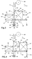
Es werden nun alle drei Bandförderer 16, 18, 20 gleichzeitig und mit gleicher
Geschwindigkeit in Förderrichtung F angetrieben und zwar so lange,
bis der zu umwickelnde Gegenstand 10' sich auf dem Auflagetisch 24 vollständig
im Umlegekanal 42 befindet und der vorgängig bereits teilweise
umwickelte Gegenstand 10 sich auf dem dritten Bandförderer 20 befindet,
wie dies Fig. 2 zeigt. Beim Fördern dieses Gegenstandes 10 vom zweiten
Bandförderer 18 auf den dritten Bandförderer 20, wird der Endabschnitt 78
gegen die Unterseite, den Boden des Gegenstandes 10 umgelegt, wobei
die beiden Endbereiche der Materialbahn miteinander in Überlappung
kommen und infolge ihrer Haftungseigenschaften sich miteinander verbinden.
Der sich auf dem dritten Bandförderer 20 befindende Gegenstand 10
ist somit vollständig umwickelt.There are now all three
Beim Fördern des anderen Gegenstandes 10' vom ersten Bandförderer 16
auf den zweiten Bandförderer 18, ist er mit seiner in Förderrichtung F gesehen
vorauslaufenden Seite an den ersten Materialbahnabschnitt 76 zur Anlage
gekommen, wodurch dieser beim Einlaufen in den Umlegekanal 42
einerseits um den Boden des Gegenstandes 10 und andererseits unter
Nachziehen ab den Vorratsschlaufen und der Vorratsrolle 68 um die obere
Seite des Gegenstandes 10 umgelegt wird. Dabei verläuft die Materialbahn
70 um die in den Figuren links gezeigte Umlenkwalze 64 der Führungseinrichtung
62, von dieser zwischen den Gegenstand 10' und dem Druckband
38 der Druckeinrichtung 30 U-förmig um den Gegenstand 10' herum bis
etwa mittig zu dessen Boden.When conveying the
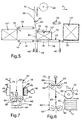
Nun wird, wie dies aus den Fig. 6 und 7 erkennbar ist, die Führungseinrichtung
62 von ihrer Ruhestellung 66 in die Trennstellung 66' bewegt.
Dadurch wird die Materialbahn 70 unter Bildung einer Materialbahnschlaufe
80 entlang der in Förderrichtung F gesehen hinteren Seite 82 des Gegenstandes
10 bis unterhalb die Fördereinrichtung 14 und die entsprechenden
Halteeinrichtungen 48, 48' hindurchgeführt; vergleiche auch Fig. 3.Now, as can be seen from FIGS. 6 and 7, the
In der Fig. 7 ist die Trennstellung 66' der Führungseinrichtung 62 gezeigt.
Beim Hindurchbewegen durch die beiden einander zugewandten Halteeinrichtungen
48 und 48' wurde die Materialbahn 70 an beide mit Unterdruck
beaufschlagten Vakuumbalken 46 angelegt, wodurch die Materialbahn 70
festgehalten ist. An einem schematisch angedeuteten Maschinengestell 84,
an welchem in nicht gezeigter aber allgemein bekannter Art und Weise die
übrigen Teile der Vorrichtung angeordnet sind, ist ein im Querschnitt U-förmiges
Auflageelement 86 befestigt. Zwischen den Schenkelenden des Auflageelements
86 und den Umlenkwalzen 64 der Führungseinrichtung 62 ist
die Materialbahn 70 festgeklemmt. Zwischen den beiden Umlenkwalzen 64
weist die Führungseinrichtung 62 ein Schneidmesser 88 auf, das aus einer
in der Fig. 6 gezeigten Rückzugsstellung etwa auf der Höhe der Achsen der
Umlenkwalzen 64 in Richtung gegen unten in eine in der Fig. 7 gezeigte
Schneidstellung über die untere Tangente an die beiden Umlenkwalzen 64
hindurch verschiebbar ist. Bei dieser Bewegung wird die festgeklemmte
Materialbahn 70 in den ersten Materialbahnabschnitt 76 und einen zweiten
Materialbahnabschnitt 90 mit dem Endabschnitt 78 aufgetrennt.7 shows the separation position 66 'of the
Wie dies der Fig. 7 entnehmbar ist, weisen die Vakuumbalken 46 einen
hohlen, im Querschnitt rechteckigen Balken auf, dessen Innenraum mit
einer schematisch angedeuteten Unterdruckquelle 92 verbunden ist, und
dessen der Materialbahn 70 zugewandte Seite mit einer Vielzahl von
Durchgangslöchern versehen ist.As can be seen in FIG. 7, the vacuum bars 46 have one
hollow, cross-sectionally rectangular beams, whose interior with
a schematically indicated
Eingangsseitig des ersten Bandförderers 16 ist in der Fig. 2 ein weiterer
Gegenstand 10", auf dem ein Deckblatt liegt, gezeigt. Die weitere Druckeinrichtung
50 ist in ihrem Abstand zum ersten Bandförderer 16 auf eine
Höhe verschoben worden, die geringfügig höher ist als die entsprechende
Abmessung des Gegenstandes 10''. The input side of the
Dieser Gegenstand 10" wird, wie in der Fig. 3 gezeigt, in den Presskanal
58 eingeführt und durch Absenken der weiteren Druckeinrichtung 50 zusammengepresst.
Auf dem Auflagetisch 24 befindet sich der vorgängig
teilweise umwickelte Gegenstand 10', wobei die Führungseinrichtung 62
sich in der in der Fig. 7 aufgezeigten Trennstellung 66' befindet und das
Schneidmesser 88 die Materialbahn 70 durchtrennt. Weiter wurde das
Druckband 38 der Druckeinrichtung 32 gleichzeitig mit jenem der weiteren
Druckeinrichtung 50 auf die gleiche Höhe abgesenkt.This
Anschliessend wird der Auflagetisch 24 um 180° um die Achse 26 gedreht.
Die dadurch erreichte Situation ist in Fig. 4 gezeigt. Gleich wie in der
Fig. 1 verläuft der erste Materialabschnitt 76 an der in Förderrichtung F gesehen
vorderen Seite des sich im Presskanal 58 befindenden Gegenstandes
10" vorbei und die Führungseinrichtung 62 wurde wieder in ihre Ruhestellung
66 angehoben. Der Umlegekanal 42 auf dem Auflagetisch 24 ist
nun für die Aufnahme des Gegenstandes 10" bereit. Die in der Fig. 4 gezeigte
Situation entspricht jener der Fig. 1.The support table 24 is then rotated through 180 ° about the
Nun werden wieder alle drei Bandförderer 16, 18, 20 und die Druckbänder
38, 54 in Förderrichtung F angetrieben, wodurch einerseits der sich im
Presskanal 58 befindende Gegenstand 10" unter Umlegen der Materialbahn
70 in den Umlegekanal 42 eingeführt wird und andererseits gleichzeitig
der andere Gegenstand 10' vom Auflagetisch 24 auf den dritten
Bandförderer 20 überführt wird, siehe Fig. 5. Dabei wird der Endabschnitt
78 an diesen Gegenstand angelegt. Ein weiterer Gegenstand 10''' ist bereit,
um zwischen den ersten Bandförderer 16 und die weitere Druckeinrichtung
50 eingeführt zu werden. Die nun frei gewordene Druckeinrichtung
30 kann dann auf die Höhe des weiteren Druckbandes 54 der weiteren
Druckeinrichtung 50 verstellt werden.Now all three
Unter Wiederholung dieser Schritte wird ein Gegenstand nach dem anderen umwickelt.Repeating these steps becomes one item at a time wrapped.
Da die Gegenstände 10, 10', 10'', 10''' während des Drehens des Auflagetisches
24 zwischen dem zweiten Bandförderer 18 und der entsprechenden
Druckeinrichtung 30, 32 zusammengepresst gehalten sind, muss
die Halteeinrichtung 48 auf den Endabschnitt 78 keine Zugkraft auswirken,
sondern nur diesen am freien Bewegen und Flattern während des Drehens
hindern. Dies ermöglicht das dauernde Verbinden der Vakuumbalken 46 mit
der Unterdruckquelle; die Materialbahn 70 kann mit geringer Zugkraft beim
jeweiligen Weiterfördern des Gegenstandes 10, 10', 10'', 10''' von den
Vakuumbalken 46 abgezogen werden. Selbstverständlich weist die Vorrichtung
eine nicht gezeigte Steuereinrichtung zum Ansteuern sämtlicher
Antriebe der Vorrichtung auf.Since the
Die gezeigte Vorrichtung eignet sich nicht nur zum Umwickeln von Stapeln von Druckereierzeugnissen, sondern auch von Paketen oder einzelnen Zeitungen, Zeitschriften oder dergleichen. Während Druckereierzeugnisse in der Regel kompressibel sind, sind dies andere quaderförmige Gegenstände nicht zwingend. Um eine Beschädigung zu vermeiden, können die Druckeinrichtungen, beispielsweise mit Drucksensoren versehen sein, um ein weiteres Absenken zu verhindern, wenn eine bestimmte Druckkraft erzielt ist. The device shown is not only suitable for wrapping stacks of printed matter, but also of packages or individual newspapers, Magazines or the like. While printed matter in are usually compressible, these are other cuboid objects not necessarily. To avoid damage, the printing devices, for example, be provided with pressure sensors in order to prevent further lowering when a certain compressive force is achieved is.
Anstelle der Förderbänder und Druckbänder sind auch Rollenbahnen geeignet.
Während die Bandförderer 14 und 20 im Start-Stopp-Betrieb angetrieben
sind, sind der zweite Bandförderer 18 sowie die Druckbänder 38
der Druckeinrichtungen 30 und 32 mittels eines reversierbaren Antriebs angetrieben.Instead of the conveyor belts and pressure belts, roller conveyors are also suitable.
While the
Es ist auch möglich, dem Auflagetisch mehr als zwei, beispielsweise drei oder vier Druckeeinrichtungen zuzuordnen. Diese sind dann in Umfangsrichtung gesehen gleichmässig verteilt und jeder Druckeinrichtung ist ein eigener reversierbarer Bandförderer oder eine entsprechende Fördereinrichtung zugeordnet.It is also possible to have more than two, for example three, on the support table or to assign four printing devices. These are then in the circumferential direction seen evenly distributed and each printing device is its own reversible belt conveyor or a corresponding conveyor assigned.
Claims (10)
- An apparatus for wrapping cuboidal articles with a web-like wrapping material, having a conveying arrangement (14) for moving along a movement path (22) the article (10) which is to be wrapped, having a guide arrangement (62) for unwinding the material web (70) from a supply roll (68) and guiding said material web (70) in a direction (V) which intersects the movement path (22), having a bearing table (24) which, as seen in the conveying direction (F) of the conveying arrangement (14), is arranged downstream of the material web (70), running transversely with respect to the movement path (22), which can be rotated about an axis (26), running at right angles to the conveying direction (F), and which is intended for the article (10) which is to be wrapped, and having a pressure-exerting arrangement (30; 32) which is arranged above the bearing table (24), forms, with the latter, a wrap-around channel (42) for the material web (70) and the article (10) which is to be wrapped, and is intended for compressing the article (10) as the latter is wrapped, it being the case that the guide arrangement (62) is intended, once the material web (70) has been wrapped around the article (10) as the latter is conveyed into the wrap-around channel (42), for guiding the material web (70) along the trailing side (82) of the article (10), as seen in the conveying direction (F), and, with the formation of a material-web loop (80), at the same time for forming, on the one hand, a first material-web section (76) and, on the other hand, a second material-web section (90), which runs on the trailing side (82) of the article (10) and of which the length is greater than the dimension of the article (10) in the longitudinal direction of said second material-web section (90), it being the case that, once the bearing table (24) has been rotated, the end section (78) of said second material-web section (90), this end section projecting beyond the article (10), is wrapped around against the article (10) as the article (10) is moved from the bearing table (24), wherein the pressure-exerting arrangement (30; 32) can be rotated about the axis (26) together with the bearing table (24) and at least two spaced-apart pressure-exerting arrangements (30, 32) which are controlled independently of one another in respect of a distance from the bearing table (24) and can be rotated about the axis (26) together with said bearing table are present.
- The apparatus as claimed in claim 1, wherein two pressure-exerting arrangements (30, 32) are arranged opposite one another symmetrically in relation to an axial plane.
- The apparatus as claimed in one of claims 1 to 2, wherein the bearing table (24) has a belt conveyor (18) which is driven reversibly.
- The apparatus as claimed in one of claims 1 to 3, wherein the pressure-exerting arrangement (30; 32) or the pressure-exerting arrangements (30, 32) has/have an endless pressure-exerting belt (38) which is guided around deflection rollers (36) and is preferably driven reversibly.
- The apparatus as claimed in one of claims 1 to 4, wherein upstream in relation to the material web (70), which intersects the movement path (22), the conveying arrangement (14) has a belt conveyor (16) which is preferably driven in start/stop operation and is assigned a further pressure-exerting arrangement (50) in order, even before it is wrapped with the material web (70), to compress the article (10) which is to be wrapped and to introduce the latter into the wrap-around channel (42) in the compressed state.
- The apparatus as claimed in one of claims 1 to 5, which comprises a retaining arrangement (48) which is preferably designed as a vacuum-producing bar (46), is arranged beneath the bearing table (24), can be rotated about the axis (26) together with the bearing table and is intended for retaining the end section (78) of the second material-web section (90) as the bearing table (24) is rotated.
- The apparatus as claimed in one of claims 1 to 6, wherein the guide arrangement (62) has axis-parallel deflection rollers (64), which can be moved at right angles to the conveying direction (F) and are intended for the material web (70), and a cutting arrangement (88), which is arranged between said deflection rollers and is intended for severing the material web (70) into the first material-web section (76) and second material-web section (90).
- The apparatus as claimed in claim 7, which comprises a bearing element (36) which is intended for clamping in the material web (70) between itself and the deflection rollers (64), for the purpose of severing said material web.
- The apparatus as claimed in one of claims 1 to 8, which comprises a further retaining arrangement (48'), which is preferably designed as a vacuum-producing bar (46) and is intended for retaining the first material-web section (76).
- A method of operating an apparatus as claimed in one of claims 1 to 9, wherein that pressure-exerting arrangement (30, 32), of the pressure-exerting arrangements (30, 32) assigned to the bearing table (24), which discharges an article (10, 10') in each case is set in accordance with the height of the further pressure-exerting arrangement once the article (10, 10') has been conveyed out of the wrap-around channel (42) and before the rotational position which faces in the direction of the material web (70) has been reached.
Applications Claiming Priority (2)
| Application Number | Priority Date | Filing Date | Title |
|---|---|---|---|
| CH138998 | 1998-06-30 | ||
| CH138998 | 1998-06-30 |
Publications (2)
| Publication Number | Publication Date |
|---|---|
| EP0968919A1 EP0968919A1 (en) | 2000-01-05 |
| EP0968919B1 true EP0968919B1 (en) | 2003-03-26 |
Family
ID=4209291
Family Applications (1)
| Application Number | Title | Priority Date | Filing Date |
|---|---|---|---|
| EP99111011A Expired - Lifetime EP0968919B1 (en) | 1998-06-30 | 1999-06-10 | Method and device for enveloping quadrangular objects with a tape-like enveloping material |
Country Status (5)
| Country | Link |
|---|---|
| US (1) | US6223500B1 (en) |
| EP (1) | EP0968919B1 (en) |
| CA (1) | CA2275791C (en) |
| DE (1) | DE59904691D1 (en) |
| DK (1) | DK0968919T3 (en) |
Families Citing this family (19)
| Publication number | Priority date | Publication date | Assignee | Title |
|---|---|---|---|---|
| DE10017562C1 (en) * | 2000-04-08 | 2001-09-06 | Continental Ag | Air spring for automobile self-leveling suspension, has integrated height sensor provided by variable length coil winding and cooperating inductive coil |
| ES2260152T3 (en) * | 2000-12-20 | 2006-11-01 | Tissue Machinery Company S.P.A. | PROCEDURE AND APPARATUS FOR PACKAGING OF PAPER BATTERIES OR SIMILAR WITH A PACKING SHEET. |
| DE10134257B4 (en) * | 2001-07-18 | 2007-04-26 | Cyklop Gmbh | packaging machine |
| DE10134258B4 (en) * | 2001-07-18 | 2006-03-09 | Cyklop Gmbh | packaging machine |
| US6761014B2 (en) * | 2002-08-16 | 2004-07-13 | Alain Cerf | Apparatus and process for wrapping articles on a conveyer |
| US7310922B2 (en) * | 2004-09-13 | 2007-12-25 | Meadwestvaco Corporation | Banded envelopes and method for assembling a package of banded envelopes |
| US7789226B2 (en) | 2004-09-13 | 2010-09-07 | Meadwestvaco Corporation | Packaged banded envelopes |
| US7360344B2 (en) * | 2004-09-17 | 2008-04-22 | Fpna Acquisition Corporation | Method and apparatus for sleeve or band-type packaging of a compressible article |
| ATE495107T1 (en) * | 2006-05-26 | 2011-01-15 | M T C Macchine Trasformazione Carta S R L | DEVICE FOR COVERING STACKS OF SHEETS |
| DE602006010034D1 (en) * | 2006-05-26 | 2009-12-10 | Mtc Macchine Trasformazione | Paper feeding device for a strapping machine for producing paper rolls |
| IT1393004B1 (en) * | 2009-02-13 | 2012-04-02 | Dolphin Pack S R L | PACKAGING MACHINE DESIGNED FOR THE COMPRESSION AND PACKAGING OF EXPANDED MATERIAL BLOCKS |
| US20110197549A1 (en) * | 2010-02-15 | 2011-08-18 | Illinois Tool Works Inc. | Method and apparatus for compressing and holding in compression woven fabric articles |
| KR101184450B1 (en) * | 2010-10-05 | 2012-09-20 | 삼성전자주식회사 | Auto packing apparatus and auto packing method |
| US9032869B2 (en) * | 2011-04-01 | 2015-05-19 | Systec Conveyors Inc. | Method for applying a strap around a load |
| US9505512B2 (en) | 2011-12-14 | 2016-11-29 | The Procter & Gamble Company | Sheet good loading device and method of loading sheet goods |
| JP5928139B2 (en) * | 2012-05-08 | 2016-06-01 | ブラザー工業株式会社 | Packaging equipment |
| ITBO20120619A1 (en) * | 2012-11-09 | 2014-05-10 | Tissue Machinery Co Spa | APPARATUS AND METHOD OF PACKAGING PANNOLIN OR OTHER SOFT HEALTH OBJECTS FOLDED DISHES. |
| JP5962450B2 (en) | 2012-11-15 | 2016-08-03 | ブラザー工業株式会社 | Packaging equipment |
| US9481481B2 (en) | 2012-11-15 | 2016-11-01 | Brother Kogyo Kabushiki Kaisha | Packaging device |
Family Cites Families (8)
| Publication number | Priority date | Publication date | Assignee | Title |
|---|---|---|---|---|
| GB865077A (en) * | 1958-01-20 | 1961-04-12 | Sig Schweiz Industrieges | Improvements in or relating to packing machines |
| GB1094351A (en) * | 1964-06-04 | 1967-12-13 | Schmermund Alfred | Improvements in or relating to wrapping machines |
| US3469368A (en) * | 1967-07-20 | 1969-09-30 | Grace W R & Co | Wrapping machine |
| US3504476A (en) * | 1967-07-20 | 1970-04-07 | Goodyear Tire & Rubber | Method of packaging |
| FR2409196A1 (en) * | 1977-11-16 | 1979-06-15 | Starpak Pty Ltd | PACKAGING PROCESS AND DEVICE |
| ATE28161T1 (en) | 1983-03-22 | 1987-07-15 | Ferag Ag | METHOD AND DEVICE FOR WRAPPING PREFERABLY CUBOID-SHAPED OBJECTS WITH A WEB-SHAPED WRAPPING MATERIAL. |
| IT1245996B (en) | 1991-05-24 | 1994-11-07 | Wrapmatic Spa | METHOD FOR THE WRAPPING OF STACKS OF PAPER AND EQUIPMENT THAT REALIZES IT. |
| DE19533086A1 (en) * | 1994-09-19 | 1996-03-21 | Ferag Ag | Method and device for stacking flat products, in particular printed products |
-
1999
- 1999-06-10 DK DK99111011T patent/DK0968919T3/en active
- 1999-06-10 DE DE59904691T patent/DE59904691D1/en not_active Expired - Fee Related
- 1999-06-10 EP EP99111011A patent/EP0968919B1/en not_active Expired - Lifetime
- 1999-06-21 CA CA002275791A patent/CA2275791C/en not_active Expired - Fee Related
- 1999-06-28 US US09/340,888 patent/US6223500B1/en not_active Expired - Fee Related
Also Published As
| Publication number | Publication date |
|---|---|
| US6223500B1 (en) | 2001-05-01 |
| CA2275791A1 (en) | 1999-12-30 |
| DK0968919T3 (en) | 2003-04-22 |
| CA2275791C (en) | 2007-08-14 |
| EP0968919A1 (en) | 2000-01-05 |
| DE59904691D1 (en) | 2003-04-30 |
Similar Documents
| Publication | Publication Date | Title |
|---|---|---|
| EP0968919B1 (en) | Method and device for enveloping quadrangular objects with a tape-like enveloping material | |
| EP0120251B1 (en) | Method and device for enveloping preferably quadrangular objects with a tape-like enveloping material | |
| DE69919493T2 (en) | Surface winder with clamp cutter | |
| DE60116994T2 (en) | WRAPPING MACHINE FOR REVERSING MATERIAL TO A SLEEVE AND CORRESPONDING WRAPPING PROCESS | |
| EP0894721B1 (en) | Method and device for tying single objects or stacks of objects | |
| DE69717894T2 (en) | Method and device for separating a material web on a weakening line | |
| DE69514112T2 (en) | RUBBER BAND CHAIN, METHOD AND DEVICE FOR THE PRODUCTION THEREOF, AND METHOD AND DEVICE FOR THE SUPPLY OF THE RUBBER BANDS TO A TREATMENT DEVICE | |
| DE60113580T2 (en) | Cutting machine for a variety of kitchen and / or toilet paper rolls | |
| DE3836214C2 (en) | ||
| DE2729605A1 (en) | DEVICE FOR SEPARATING ALTERNATE LAYERS FROM A SINGLE STACK | |
| AT394021B (en) | DEVICE FOR PROMOTING OBJECTS | |
| EP0890509A1 (en) | Method and device for tying single objects or stacks of objects | |
| DE69702274T2 (en) | Device for collecting and stacking layered materials, and a stacking method | |
| DE69301973T2 (en) | Device for feeding and cutting a film for wrapping objects in a packaging machine | |
| EP0313781A2 (en) | Device for making portable tubular packages of printing products | |
| DE69708653T2 (en) | CROSS-CUTTING DEVICE FOR A WRAPPING MACHINE | |
| DE3143436A1 (en) | DEVICE FOR REWINDING A MATERIAL | |
| DE4016484A1 (en) | Packing device for rolls of paper webs - has chain conveyor with stepped action and associated positioning and folding devices | |
| DE1806918A1 (en) | Method and device for making bags | |
| EP0100462A2 (en) | Web winding device | |
| DE2529126B2 (en) | Device for feeding weft threads to a warp knitting machine | |
| DE69506060T2 (en) | Device for cutting and glue-free application of the start of the web for a new winding roll on the winding core of a winder | |
| EP0849179B1 (en) | Device for packaging a roll of web material by means of packaging web | |
| DE60124366T2 (en) | Circumferentially driven winding machine and method for producing rolls of web material | |
| DE19817870B4 (en) | Winding device for a web |
Legal Events
| Date | Code | Title | Description |
|---|---|---|---|
| PUAI | Public reference made under article 153(3) epc to a published international application that has entered the european phase |
Free format text: ORIGINAL CODE: 0009012 |
|
| AK | Designated contracting states |
Kind code of ref document: A1 Designated state(s): CH DE DK GB IT LI NL SE |
|
| AX | Request for extension of the european patent |
Free format text: AL;LT;LV;MK;RO;SI |
|
| 17P | Request for examination filed |
Effective date: 20000119 |
|
| AKX | Designation fees paid |
Free format text: CH DE DK GB IT LI NL SE |
|
| 17Q | First examination report despatched |
Effective date: 20010621 |
|
| GRAH | Despatch of communication of intention to grant a patent |
Free format text: ORIGINAL CODE: EPIDOS IGRA |
|
| GRAH | Despatch of communication of intention to grant a patent |
Free format text: ORIGINAL CODE: EPIDOS IGRA |
|
| GRAA | (expected) grant |
Free format text: ORIGINAL CODE: 0009210 |
|
| AK | Designated contracting states |
Designated state(s): CH DE DK GB IT LI NL SE |
|
| REG | Reference to a national code |
Ref country code: GB Ref legal event code: FG4D Free format text: NOT ENGLISH |
|
| REG | Reference to a national code |
Ref country code: CH Ref legal event code: EP |
|
| REG | Reference to a national code |
Ref country code: CH Ref legal event code: NV Representative=s name: PATENTANWAELTE SCHAAD, BALASS, MENZL & PARTNER AG |
|
| GBT | Gb: translation of ep patent filed (gb section 77(6)(a)/1977) |
Effective date: 20030326 |
|
| REG | Reference to a national code |
Ref country code: DK Ref legal event code: T3 |
|
| REF | Corresponds to: |
Ref document number: 59904691 Country of ref document: DE Date of ref document: 20030430 Kind code of ref document: P |
|
| REG | Reference to a national code |
Ref country code: SE Ref legal event code: TRGR |
|
| PLBE | No opposition filed within time limit |
Free format text: ORIGINAL CODE: 0009261 |
|
| STAA | Information on the status of an ep patent application or granted ep patent |
Free format text: STATUS: NO OPPOSITION FILED WITHIN TIME LIMIT |
|
| 26N | No opposition filed |
Effective date: 20031230 |
|
| REG | Reference to a national code |
Ref country code: CH Ref legal event code: PFA Owner name: FERAG AG Free format text: FERAG AG#ZUERICHSTRASSE 74#8340 HINWIL (CH) -TRANSFER TO- FERAG AG#PATENTABTEILUNG Z. H. MARKUS FELIX ZUERICHSTRASSE 74#8340 HINWIL (CH) |
|
| PGFP | Annual fee paid to national office [announced via postgrant information from national office to epo] |
Ref country code: DK Payment date: 20080610 Year of fee payment: 10 Ref country code: CH Payment date: 20080625 Year of fee payment: 10 |
|
| PGFP | Annual fee paid to national office [announced via postgrant information from national office to epo] |
Ref country code: IT Payment date: 20080624 Year of fee payment: 10 |
|
| PGFP | Annual fee paid to national office [announced via postgrant information from national office to epo] |
Ref country code: SE Payment date: 20080612 Year of fee payment: 10 Ref country code: NL Payment date: 20080618 Year of fee payment: 10 Ref country code: DE Payment date: 20080620 Year of fee payment: 10 |
|
| PGFP | Annual fee paid to national office [announced via postgrant information from national office to epo] |
Ref country code: GB Payment date: 20080620 Year of fee payment: 10 |
|
| REG | Reference to a national code |
Ref country code: CH Ref legal event code: PL |
|
| REG | Reference to a national code |
Ref country code: DK Ref legal event code: EBP |
|
| GBPC | Gb: european patent ceased through non-payment of renewal fee |
Effective date: 20090610 |
|
| NLV4 | Nl: lapsed or anulled due to non-payment of the annual fee |
Effective date: 20100101 |
|
| PG25 | Lapsed in a contracting state [announced via postgrant information from national office to epo] |
Ref country code: LI Free format text: LAPSE BECAUSE OF NON-PAYMENT OF DUE FEES Effective date: 20090630 Ref country code: CH Free format text: LAPSE BECAUSE OF NON-PAYMENT OF DUE FEES Effective date: 20090630 |
|
| PG25 | Lapsed in a contracting state [announced via postgrant information from national office to epo] |
Ref country code: GB Free format text: LAPSE BECAUSE OF NON-PAYMENT OF DUE FEES Effective date: 20090610 |
|
| PG25 | Lapsed in a contracting state [announced via postgrant information from national office to epo] |
Ref country code: DE Free format text: LAPSE BECAUSE OF NON-PAYMENT OF DUE FEES Effective date: 20100101 |
|
| PG25 | Lapsed in a contracting state [announced via postgrant information from national office to epo] |
Ref country code: NL Free format text: LAPSE BECAUSE OF NON-PAYMENT OF DUE FEES Effective date: 20100101 Ref country code: DK Free format text: LAPSE BECAUSE OF NON-PAYMENT OF DUE FEES Effective date: 20090630 |
|
| PG25 | Lapsed in a contracting state [announced via postgrant information from national office to epo] |
Ref country code: IT Free format text: LAPSE BECAUSE OF NON-PAYMENT OF DUE FEES Effective date: 20090610 |
|
| PG25 | Lapsed in a contracting state [announced via postgrant information from national office to epo] |
Ref country code: SE Free format text: LAPSE BECAUSE OF NON-PAYMENT OF DUE FEES Effective date: 20090611 |