EP0313781A2 - Device for making portable tubular packages of printing products - Google Patents
Device for making portable tubular packages of printing products Download PDFInfo
- Publication number
- EP0313781A2 EP0313781A2 EP88114902A EP88114902A EP0313781A2 EP 0313781 A2 EP0313781 A2 EP 0313781A2 EP 88114902 A EP88114902 A EP 88114902A EP 88114902 A EP88114902 A EP 88114902A EP 0313781 A2 EP0313781 A2 EP 0313781A2
- Authority
- EP
- European Patent Office
- Prior art keywords
- winding mandrel
- film
- roller
- roll
- printed products
- Prior art date
- Legal status (The legal status is an assumption and is not a legal conclusion. Google has not performed a legal analysis and makes no representation as to the accuracy of the status listed.)
- Granted
Links
Images


Classifications
-
- B—PERFORMING OPERATIONS; TRANSPORTING
- B65—CONVEYING; PACKING; STORING; HANDLING THIN OR FILAMENTARY MATERIAL
- B65B—MACHINES, APPARATUS OR DEVICES FOR, OR METHODS OF, PACKAGING ARTICLES OR MATERIALS; UNPACKING
- B65B63/00—Auxiliary devices, not otherwise provided for, for operating on articles or materials to be packaged
- B65B63/04—Auxiliary devices, not otherwise provided for, for operating on articles or materials to be packaged for folding or winding articles, e.g. gloves or stockings
-
- B—PERFORMING OPERATIONS; TRANSPORTING
- B65—CONVEYING; PACKING; STORING; HANDLING THIN OR FILAMENTARY MATERIAL
- B65B—MACHINES, APPARATUS OR DEVICES FOR, OR METHODS OF, PACKAGING ARTICLES OR MATERIALS; UNPACKING
- B65B25/00—Packaging other articles presenting special problems
- B65B25/14—Packaging paper or like sheets, envelopes, or newspapers, in flat, folded, or rolled form
- B65B25/146—Packaging paper or like sheets, envelopes, or newspapers, in flat, folded, or rolled form packaging rolled-up articles
Definitions
- the present invention relates to a device for producing portable, tubular packages from printed products, such as newspapers, magazines and the like, which are wound into a roll and fed in scale formation, according to the preamble of claim 1.
- the present invention has for its object to provide a device that allows the production of printed product packages of this type.
- the means for applying the printed products to the winding mandrel have an endless, preferably circumferentially driven band element around which the printed element and the holding element are guided, at least during the winding of the printed product. wherein the supplied printed products are inserted between the winding mandrel and the band element.
- a belt conveyor which can be moved from the area thereof, is arranged below the winding mandrel, and the winding mandrel or the roller can be loosely rotatably supported on its conveyor-effective strand.
- the belt conveyor With the belt conveyor, the printed products can be guided undershot to the winding mandrel and wound thereon, the position of the winding mandrel automatically adapting to the thickness of the printed products already wound relative to the conveying strand of the belt conveyor. Because the belt conveyor is displaceable from the area of the winding mandrel, the winding mandrel or the package wound on it can be exposed for ejection without the height adjustment of the winding mandrel having to be driven.
- the scale formation runs cleanly into the conveying gap between the belt element and the winding mandrel or the printed products already wound on the winding mandrel.
- the winding mandrel is rotatably arranged on a pivot lever which is pivotably mounted about an axis parallel to the winding mandrel, the lower end position of which is determined by a stop element in such a way that the axis of the winding mandrel runs above the conveying strand.
- the delivery device preferably has means for unwinding the film from the supply roll, for severing the section and for feeding it into the path of movement of the scale formation. This greatly simplifies the handling of the holding elements.
- the delivery device has a belt conveyor which can be driven all round for feeding the film into the path of movement of the scale formation, the film which has been unwound from the supply roll rests against the conveying section.
- the film can be tensioned and fed without wrinkles.
- the means for unwinding have two parallel, spaced apart, rotatably mounted unwinding rollers for rotatably, loosely supporting the supply roll, at least one of which can be driven, preferably by braking.
- Replacing the supply rolls is greatly simplified by loosely placing the new roll on the unwinding rolls can be placed.
- a tensile stress can be built up in the unwound film, which allows a full wrapping of the roll and thus leads to compact packages.
- the belt conveyor is preceded by a braking element which can be brought into action on the film.
- the film remains tensioned even when the unwinding process is finished.
- the belt conveyor can rotate continuously so that the film, brought back by the braking element, slides frictionally on the conveying strand or the conveying strand and thus maintains the internal tension.
- FIGS. 1 and 2 A device for forming printed product packages with a holding element running around the roll of printed products will now be explained with reference to FIGS. 1 and 2.
- the device mentioned has a frame designated by 10, in which two belt conveyors 12 and 14 are arranged one behind the other.
- the first belt conveyor 12 which is only partially shown, is used to feed the printed products 16 which are to be wound up into a roll and accumulate in scale formation S to a winding point 18.
- the conveying direction of the belt conveyor 12 driven in rotation is designated by B in FIG. 1.
- each printed product 16 lies on the subsequent printed product. This means that the leading edges 16a of the printed products 16 lie in the scaly formation S that is fed in on the underside thereof.
- the second belt conveyor 14 is arranged in a carriage 20, which is supported by means of two guide rods 22, only one is visible in FIG.
- a cylindrical winding mandrel 30 which is freely rotatably mounted on a pivot lever 32, which in turn is pivotably seated on a shaft 34.
- the pivot lever 32 and with this the winding mandrel 30 can be pivoted in the direction of arrow D (FIG. 1).
- the pivot lever 32 and the winding mandrel 30 is shown with solid lines in its lower pivot position, while the upper pivot position of the pivot lever 32 and the winding mandrel 30 is dot-dash and designated 32 'and 30'. In its lower pivot position, the pivot lever 32 is in contact with a stop 36.
- the winding device also includes an endless belt 38 which is guided over a number of deflection rollers 40-52.
- the deflection rollers 40, 42, 44 and 48 are fixed in the frame 10
- the deflection rollers 49 and 50 are mounted in the carriage 20, while the deflection rollers 46 and 52 are pivotally mounted.
- the deflection roller 46 is mounted on one end of a lever 54 which is pivotally and clockwise biased on a shaft 56 at the other end, the longitudinal axis of which coincides with the axis of rotation of the deflection roller 48.
- the lever 54 and with this the deflection roller 46 can reciprocate in the direction of the arrow E (FIG. 1) swing.
- One end position of the lever 54 and roller 46 is shown with solid lines, while the other end position is shown with dash-dotted lines and is denoted by 54 'and 46'.
- the deflecting roller 52 is mounted at one end of a two-armed lever 58 which is pivotably mounted about a shaft 60 arranged on the frame 10 in the direction of the arrow F (FIG. 1).
- a cylinder-piston unit 62 engages, which pivots the lever 58 together with the deflection roller 52 into the upper end position 58 ', 52' shown with solid lines.
- the lower end position of the lever 58 and the deflection roller 52 is shown in broken lines.
- the deflection roller 40 is driven clockwise by the drive unit 64, so that the belt 38 is driven in a rotating manner in the direction of the arrow G (FIG. 1).
- a friction drive 66 drives the belt conveyor 14 in the active position shown in phantom in the direction of arrow H (FIG. 1).
- a plate-shaped ejector 68 which is fastened to one end of a rod 70 which is guided in a guide bearing 72 in the direction of the arrow L (FIG. 2) so as to be displaceable.
- a cylinder-piston unit 74 acts thereon (FIG. 2).
- the fully extended position of the ejector 68 is shown in broken lines and designated 68 '.
- a support table 78 is additionally arranged on the frame 10 by means of a support 76. The finished ones come out on him printed product packages 80 to the edition.
- a delivery device 82 for holding elements 84 opens into the movement path of the scale formation S.
- the holding element 84 is indicated by dash-dotted lines on the finished printed product package 80 in FIG. 2.
- Two parallel unwinding rollers 86, 88 are rotatably mounted on the frame 10, the unwinding roller 88 being operatively connected to a roller 92 by means of a chain 90.
- a supply roll 94 is placed, the film 94 'around which is fixed on the frame 10 and rotatably mounted deflection rolls 96, 98 and 100 to the roller 92 and one of these downstream belt conveyor 102.
- the film 94 ' is wound up in the supply roll 94 on a winding core 104, which comes to rest in the fully unwound state on the two unwinding rolls 86, 88, as shown in broken lines.
- the roller 92 is mounted on a shaft 114 and coupled to one side of a magnetic coupling 115.
- the roller 92 is operatively connected to the chain 90, while another chain 116, which is connected to the belt conveyor 102 is operatively connected, can be brought into operative connection with the roller 92 by means of the magnetic coupling 115.
- a brake unit 118 is also supported on the frame 10, the brake head 120 of which can be brought into braking action on the roller 92.
- Another roller 122 acts on the outside of the film 94 'guided around the roller 92. It is mounted on a pivotable and against the film 94 'biased frame 124, and it can only turn in the feed direction K of the film 94' due to a freewheel arranged therein, while an opposite rotation is prevented by the freewheel.
- the belt conveyor 102 has an endless belt 130 guided around two fixed rollers 126 and 128, on the conveyor-effective strand of which the film 94 'bears.
- a plurality of belts running parallel to one another can also be present instead of one belt 130.
- the roller 126 is operatively connected to a conveyor roller 134 which is also rotatably mounted on the frame 10.
- the conveyor roller 134 bears against the friction drive 66, as a result of which the latter is also rotated.
- the conveyor roller 134 is driven by the drive unit 64 by means of a drive chain 136.
- a cutting device 138 is pivotally mounted, which can be pivoted by means of a further cylinder-piston unit 140 from a rest position shown in solid lines to a cutting position shown in broken lines.
- the cutting device 138 is described in more detail with the aid of FIGS. 1 and 3.
- a lever arm 144 is pivotally mounted, on the free end of which the cylinder-piston unit 140 engages.
- a bracket 146 extending parallel to the axis of the pivot pins 142 is attached to the lever arm, at the ends of which a leaf spring 148 is arranged.
- Insulating bodies 150 are provided on the free ends of the leaf springs 148, to which holding pins 152 are fastened.
- a heating wire 154 is stretched between the holding pins 152 and is wound around the holding pins 152 at both ends.
- the connecting wires for the power supply for heating the heating wire 154 are denoted by 156. 3
- the rest position of the cutting device 138 is shown with solid lines, the heating wire 154 having expanded as a result of the heat.
- it contracts so that the ends of the leaf springs 148 come closer to one another, which is shown by dash-dotted lines, which are designated by 148 '(Fig. 3).
- the heating wire 154 is located in the region of the conveyor roller 134 and is shown when it is pivoted into the cutting position, shown in broken lines, through the film 94 'between the belt conveyor 102 and the conveyor roller 134.
- the film section fed to the winding point 18 is separated from the film 94 '.
- This separated film section serves as a holding element 84.
- the cutting device 138 pivots back into the rest position.
- the operation of the device for producing portable, tubular Print product packages 80 consisting of printed products 16 wound into a roll, fed in scale formation S, and a holding element 84 running around the roll for holding the roll together.
- the functioning of the delivery device 82 for the holding element 84 is initially specified.
- the conveyor roller 134 and the roller 126 of the belt conveyor 102 are driven in a clockwise direction, so that the conveyor-effective strand of the belt 130 moves in the direction of the arrow K. If no foil section serving as a holding element 84 is to be fed to the winding point 18, the magnetic coupling 115 is released and the roller 92 is prevented from rotating due to the extended brake head 120 of the brake unit 118.
- the film 94 ' Since the film 94 'is clamped against the roller 92 by the further roller 122 biased against it, the film 94' cannot advance in the direction of the arrow K. The end portion of the film 94 'extending from the roller 92 to the area of the heating wire 154' thus slidably abuts the conveyor-effective strand of the belt conveyor 102. Since the chain 90 is also decoupled from the chain 116 as a result of the magnetic coupling 115 being released, the supply roll 94 cannot rotate, and as a result of the weight lever 106, the film is stretched between the supply roll 94 and the roller 92.
- the brake head 120 is lifted off the roller 92 by means of the brake unit 118 and the magnetic clutch 115 is activated.
- the free running of the roller 122 prevents the film 94 'from running back against the direction of the arrow K.
- the roller 92 begins to rotate clockwise, so that free end of the film 94 'in the direction of the arrow K and H of the winding point 18 is supplied.
- the unwinding speed from the supply roller 94 is lower than the speed at which the film 94 'is conveyed from the roller 92 to the belt conveyor 102.
- This extension can be maintained with the aid of the belt conveyor 102 and the conveyor roller 134 up to the winding point 118.
- the film 94 ' is an elastic plastic that responds to this extension with a tensile force, which gives the roll of printed products 16 wrapped around it a good hold.
- the magnetic coupling 115 is released, and the free running of the roller 122 prevents movement of the film 94' against the direction of the arrow K.
- the roller 92 is braked by means of the brake unit 118, whereby the supply roll 94 also comes to a standstill.
- the belt conveyor 102 continues to move, so that the extension of the part of the film 94 'resting on it remains'.
- the film 94 ' is separated by means of the heated heating wire 154 from the winding 18 supplied section.
- the cutting device 138 pivots back into the rest position.
- the pivot lever 32 with the winding mandrel 30 is in the lower position, shown in solid lines, while the deflection roller 52 is shown in dash-dotted lines and Deflection roller 46 assumes the end position shown with solid lines.
- the belt 38 now runs from the deflection roller 40 via the deflection rollers 42 and 44 to the deflection roller 46, from this in turn via the deflection roller 44 to the deflection roller 48.
- the belt 38 runs around the deflection roller 49 and along the belt conveyor belt located below 14 up to the deflection roller 50 and then parallel to the upper run to the winding mandrel 30, which is wrapped around by the belt 38 along part of its circumference, and then continuously via the deflection roller 52 to the deflection roller 40.
- the belt 38 is shown partly in dash-dot lines.
- the scale formation S fed by the belt conveyor 12 passes over the roller 128 of the belt conveyor 102 and the conveyor roller 134 on the second belt conveyor 14 and the belt 38 to the winding mandrel 30, which is driven by the belt 38 in the counterclockwise direction.
- the supplied scale formation S is wound between the mandrel 30 and the belt 38 lying on the mandrel 30.
- the winding mandrel 30 With increasing radius of the formed product roll, which rests on the belt conveyor 14, the winding mandrel 30 is raised and pivoted upward about the pivot axis defined by the shaft 34 in the direction of arrow D, as shown in broken lines in FIG. 1.
- the lever 54 pivots with the deflection roller 46 in the counterclockwise direction from the position labeled 54 or 46 in the direction of arrow E against the end position labeled 54 'or 46'.
- the free end of the film 94 ' together with these printed products 16 of the winding 18 is supplied. Since the printed products 16 come to rest on the film 94 ', the part of the film section trailing the shingled stream S envelops after winding, the roll formed on the winding mandrel 30 from printed products 16.
- the film becomes 94 'severed.
- the two-armed lever 58 is pivoted back by means of the cylinder-piston unit 62 into the position denoted by 58 ', and at the same time the cylinder-piston unit 28 pulls the carriage 20 back from the position shown in broken lines to the position shown in solid lines.
- the printed product package 80 rolls off the belt conveyor 14 and pivots from the position shown in broken lines in the direction of arrow D into the lower end position defined by solid lines and by the stop 36.
- the winding mandrel 30 pivots back into the effective area of the ejector 68, which, by activating the cylinder-piston unit 74, pushes the finished printed product package 80 off the winding mandrel and conveys it to the support table 78 and is immediately pulled back into the starting position.
- the device By pushing the carriage 20 again into the position shown in dash-dotted lines and the two-armed lever 58 into the position 58, also indicated by dashed lines, the device is ready for the production of a further printed product package 80.
- supply roll 94 can be braked by other means than the chain 90 and the unwind roll 88, e.g. by a brake acting on the peripheral surface of the supply roll.
- film sections are separated from the supply roll 94 before they are fed to the movement path of the scale formation S and thus to the winding point 18.
- the holding element is preferably a transparent plastic film 94 'with self-adhesive properties.
Abstract
Description
Die vorliegende Erfindung betrifft eine Vorrichtung zum Herstellen von tragbaren, rohrförmigen Paketen aus zu einer Rolle aufgewickelten, in Schuppenformation zugeführten Druckprodukten, wie Zeitungen, Zeitschriften und dergleichen gemäss dem Oberbegriff des Anspruches 1.The present invention relates to a device for producing portable, tubular packages from printed products, such as newspapers, magazines and the like, which are wound into a roll and fed in scale formation, according to the preamble of
Aus der DE-OS 33 30 485 bzw. der dieser inhaltlich entsprechenden GB-OS 2 126 188 ist es bekannt, durch Aufrollen von in Schuppenformation anfallenden Druckprodukten zu einer Rolle, ein versandbereites Paket zu bilden, das sich von Hand transportieren lässt und dem die einzelnen Druckprodukte vom Zentrum des Paketes her entnommen werden können. Das Auseinanderfallen der Rolle wird durch ein, um diese herumgelegtes Halteelement, eine Umhüllung oder Umreifung, verhindert.From DE-OS 33 30 485 or the content of this corresponding GB-OS 2 126 188 it is known to form a ready-to-ship package that can be transported by hand by rolling up printed products resulting in scale formation and that can be transported by hand individual printed products can be removed from the center of the package. The roll is prevented from falling apart by a holding element wrapped around it, a wrapping or strapping.
Der vorliegenden Erfindung liegt nun die Aufgabe zugrunde, eine Vorrichtung zu schaffen, die die Herstellung von Druckproduktepaketen dieser Art erlaubt.The present invention has for its object to provide a device that allows the production of printed product packages of this type.
Diese Aufgabe wird erfindungsgemäss durch die Merkmale des kennzeichnenden Teiles des Anspruches 1 gelöst.This object is achieved according to the invention by the features of the characterizing part of
In einer bevorzugten Ausführungsform weisen die Mittel zum Anlegen der Druckprodukte an den Wickeldorn ein, um diesen mindestens während dem Aufwickeln der Druckprodukte und des Halteelementes herumgeführtes, endloses, vorzugsweise umlaufend angetriebenes Bandelement auf, wobei die zugeführten Druckprodukte zwischen den Wickeldorn und das Bandelement eingeführt werden. Dies erlaubt, auf einfache Art und Weise ein kompaktes Aufwickeln der Druckprodukte. Auf einen Antrieb für den Wickeldorn kann verzichtet werden, wenn das Bandelement umlaufend angetrieben ist. Die aufzuwickelnden Druckprodukte übertragen die Bewegung des Bandelementes auf den Wickeldorn.In a preferred embodiment, the means for applying the printed products to the winding mandrel have an endless, preferably circumferentially driven band element around which the printed element and the holding element are guided, at least during the winding of the printed product. wherein the supplied printed products are inserted between the winding mandrel and the band element. This allows a compact winding of the printed products in a simple manner. There is no need for a drive for the winding mandrel if the belt element is driven in rotation. The printed products to be wound up transfer the movement of the band element to the winding mandrel.
In einer weiteren bevorzugten Ausführungsform ist unterhalb dem Wickeldorn ein, aus dessen Bereich verschiebbarer Bandförderer angeordnet, auf dessen förderwirksamen Trum der Wickeldorn bzw. die Rolle lose drehbar zur Auflage bringbar ist. Mit dem Bandförderer können die Druckprodukte unterschlächtig zum Wickeldorn geführt und auf diesen aufgewickelt werden, wobei sich die Lage des Wickeldorns gegenüber dem förderwirksamen Trum des Bandförderers automatisch der Dicke der bereits aufgewickelten Druckprodukte anpasst. Dadurch, dass der Bandförderer aus dem Bereich des Wickeldornes verschiebbar ist, kann der Wickeldorn bzw. das auf ihn aufgewickelte Paket für das Ausstossen freigelegt werden, ohne dass der Wickeldorn in seiner Höheneinstellung angetrieben sein muss.In a further preferred embodiment, a belt conveyor, which can be moved from the area thereof, is arranged below the winding mandrel, and the winding mandrel or the roller can be loosely rotatably supported on its conveyor-effective strand. With the belt conveyor, the printed products can be guided undershot to the winding mandrel and wound thereon, the position of the winding mandrel automatically adapting to the thickness of the printed products already wound relative to the conveying strand of the belt conveyor. Because the belt conveyor is displaceable from the area of the winding mandrel, the winding mandrel or the package wound on it can be exposed for ejection without the height adjustment of the winding mandrel having to be driven.
Dadurch, dass das Bandelement am Bandförderer mindestens über einen, dem Wickeldorn vorgelagerten Teilbereich zum förderwirksamen Trum parallel geführt ist, erfolgt ein sauberes Einlaufen der Schuppenformation in den Förderspalt zwischen dem Bandelement und dem Wickeldorn bzw. den bereits auf den Wickeldorn aufgewickelten Druckprodukten.Due to the fact that the belt element on the belt conveyor is guided parallel to the conveyor-effective strand at least over a section upstream of the winding mandrel, the scale formation runs cleanly into the conveying gap between the belt element and the winding mandrel or the printed products already wound on the winding mandrel.
In einer weiteren bevorzugten Ausführungsform ist der Wickeldorn an einem, um eine Achse parallel zum Wickeldorn schwenkbar gelagerten Schwenkhebel drehbar angeordnet, dessen untere Endlage durch ein Anschlagelement derart bestimmt ist, dass die Achse des Wickeldorns oberhalb dem förderwirksamen Trum verläuft. Dadurch wird sichergestellt, dass beim Verschieben des Bandförderers in dem Bereich des Wickeldorns dieser auf den förderwirksamen Trum zur Auflage kommt. Des weiteren wird dadurch die Lage des Paketes für das Abstossen ab dem Wickeldorn festgelegt.In a further preferred embodiment, the winding mandrel is rotatably arranged on a pivot lever which is pivotably mounted about an axis parallel to the winding mandrel, the lower end position of which is determined by a stop element in such a way that the axis of the winding mandrel runs above the conveying strand. This ensures that when the belt conveyor is moved in the region of the winding mandrel, it comes to rest on the conveyor-effective strand. Furthermore, the position of the package for pushing off from the winding mandrel is determined.
Die Liefereinrichtung weist in bevorzugter Weise Mittel zum Abwickeln der Folie ab der Vorratsrolle zum Abtrennen des Abschnittes sowie zum Zuführen desselben in die Bewegungsbahn der Schuppenformation aus. Die Handhabung der Halteelemente wird dadurch stark vereinfacht.The delivery device preferably has means for unwinding the film from the supply roll, for severing the section and for feeding it into the path of movement of the scale formation. This greatly simplifies the handling of the holding elements.
In bevorzugter Weise weist die Liefereinrichtung einen umlaufend antreibbaren Bandförderer zum Zuführen der Folie in die Bewegungsbahn der Schuppenformation auf, an dessen förderwirksamen Trum die von der Vorratsrolle abgewickelte Folie anliegt. Die Folie kann gespannt und faltenlos zugeführt werden.In a preferred manner, the delivery device has a belt conveyor which can be driven all round for feeding the film into the path of movement of the scale formation, the film which has been unwound from the supply roll rests against the conveying section. The film can be tensioned and fed without wrinkles.
In einer weiteren bevorzugten Ausführungsform weisen die Mittel zum Abwickeln zwei parallele, voneinander beabstandete, drehbar gelagerte Abwickelrollen zum drehbaren, losen Abstützen der Vorratsrolle auf, von denen mindestens eine, vorzugsweise bremsend antreibbar ist. Das Auswechseln der Vorratsrollen wird stark vereinfacht, indem die neue Rolle lose auf die Abwickelrollen gelegt werden kann. Durch die Bremsung der Abwickelrolle kann in der abgewickelten Folie eine Zugspannung aufgebaut werden, was ein sattes Umwickeln der Rolle erlaubt und somit zu kompakten Paketen führt.In a further preferred embodiment, the means for unwinding have two parallel, spaced apart, rotatably mounted unwinding rollers for rotatably, loosely supporting the supply roll, at least one of which can be driven, preferably by braking. Replacing the supply rolls is greatly simplified by loosely placing the new roll on the unwinding rolls can be placed. By braking the unwinding roll, a tensile stress can be built up in the unwound film, which allows a full wrapping of the roll and thus leads to compact packages.
In bevorzugter Weise ist dem Bandförderer ein auf die Folie zur Einwirkung bringbares Bremsorgan vorgeschaltet. Die Folie bleibt auch dann gespannt, wenn der Abwickelvorgang beendet ist. Der Bandförderer kann stetig umlaufen, so dass die Folie, vom Bremsorgan zurückgeholten, auf dem förderwirksamen Trum oder den förderwirksamen Trums reibend gleitet und somit die innere Spannung beibehält.In a preferred manner, the belt conveyor is preceded by a braking element which can be brought into action on the film. The film remains tensioned even when the unwinding process is finished. The belt conveyor can rotate continuously so that the film, brought back by the braking element, slides frictionally on the conveying strand or the conveying strand and thus maintains the internal tension.
Weitere bevorzugte Ausführungsformen der Vorrichtung sind in den weiteren abhängigen Ansprüchen angegeben.Further preferred embodiments of the device are specified in the further dependent claims.
Im folgenden wird ein Ausführungsbeispiel der vorliegenden Erfindung anhand der Zeichnung näher erläutert. Es zeigen rein schematisch:
- Fig. 1 in Seitenansicht bzw. im Schnitt entlang der Linie I-I in Fig. 2 eine Vorrichtung zum Herstellen von rohrförmigen Druckproduktepaketen,
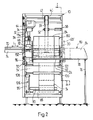
- Fig. 2 die Vorrichtung gemäss Fig. 1 in Vorderansicht in Richtung des Pfeiles A in Fig. 1, wobei gewisse Bauteile weggelassen sind, und
- Fig. 3 in Vorderansicht in Richtung des Pfeiles A in Fig. 1 die vergrössert dargestellte Schneidevorrichtung zum Trennen der Folie, wobei auch gewisse Bauteile weggelassen sind.
- 1 in side view or in section along the line II in Fig. 2, a device for producing tubular printed product packages,
- Fig. 2 shows the device of FIG. 1 in a front view in the direction of arrow A in Fig. 1, with certain components being omitted, and
- Fig. 3 in front view in the direction of arrow A in Fig. 1 the enlarged Cutting device for separating the film, certain components also being omitted.
Im folgenden wird nun anhand der Figuren 1 und 2 eine Vorrichtung zur Bildung von Druckproduktepaketen mit einem um die Rolle aus Druckprodukten herumverlaufenden Halteelement erläutert.A device for forming printed product packages with a holding element running around the roll of printed products will now be explained with reference to FIGS. 1 and 2.
Die genannte Vorrichtung weist ein mit 10 bezeichnetes Gestell auf, in dem hintereinander zwei Bandförderer 12 und 14 angeordnet sind. Der erste, nur teilweise dargestellte Bandförderer 12 dient zum Zuführen der zu einer Rolle aufzuwickelnden, in Schuppenformation S anfallenden Druckprodukte 16 zu einer Aufwickelstelle 18. Die Förderrichtung des umlaufend angetriebenen Bandförderers 12 ist in Fig. 1 mit B bezeichnet. In der zugeführten Schuppenformation S liegt jeweils jedes Druckprodukt 16 auf dem nachfolgenden Druckprodukt auf. Dies bedeutet, dass die vorlaufenden Kanten 16a der Druckprodukte 16 in der zugeführten Schuppenformation S auf deren Unterseite liegen. Der zweite Bandförderer 14 ist in einem Schlitten 20 angeordnet, der mittels zweier Führungsstangen 22, in Fig. 1 ist nur eine sichtbar, in einer am Gestell 10 angeordneten Führung 24 in Richtung des Pfeiles C hin und her verschiebbar gelagert ist. An diesem Schlitten 20 greift der eine Arm eines Winkelhebels 26 an, der um die Welle 26a verschwenkbar im Gestell 10 gelagert ist. Der andere Arm des Winkelhebels 26 ist an eine Zylinder-Kolbeneinheit 28 gekoppelt. Mittels dieser Zylinder-Kolbeneinheit 28 wird der Winkelhebel 26 in die mit 26′ bezeichnete Stellung verschwenkt und dabei der Schlitten 20 in Richtung des Pfeiles C verschoben, um den Bandförderer 14 aus der in Fig. 1 strichpunktiert dargestellten Wirkstellung, in der sich dieser Bandförderer 14 an der Aufwickelstelle 18 befindet, in eine Freigabestellung zurückzuziehen, die in Fig. 1 mit ausgezogenen Linien dargestellt und mit 14′ bezeichnet ist.The device mentioned has a frame designated by 10, in which two
An der Aufwickelstelle 18 befindet sich weiter ein zylindrischer Wickeldorn 30, der frei drehbar an einem Schwenkhebel 32 gelagert ist, welcher wiederum schwenkbar auf einer Welle 34 sitzt. Der Schwenkhebel 32 und mit diesem der Wickeldorn 30 ist in Richtung des Pfeiles D (Fig. 1) schwenkbar. In der Fig. 1 ist der Schwenkhebel 32 und der Wickeldorn 30 mit ausgezogenen Linien in ihrer unteren Schwenklage dargestellt, während die obere Schwenklage des Schwenkhebels 32 und des Wickeldorns 30 strichpunktiert und mit 32′ bzw. 30′ bezeichnet ist. In seiner unteren Schwenklage steht der Schwenkhebel 32 an einem Anschlag 36 an.At the
Zur Aufwickelvorrichtung gehört weiter ein endloser Riemen 38, der über eine Anzahl von Umlenkrollen 40 - 52 geführt ist. Von letzteren sind die Umlenkrollen 40, 42, 44 und 48 im Gestell 10 ortsfest gelagert, die Umlenkrollen 49 und 50 sind im Schlitten 20 gelagert, während die Umlenkrollen 46 und 52 schwenkbar gelagert sind. Zu diesem Zwecke ist die Umlenkrolle 46 am einen Ende eines Hebels 54 gelagert, der am andern Ende schwenkbar und im Uhrzeigersinn vorgespannt auf einer Welle 56 sitzt, deren Längsachse mit der Drehachse der Umlenkrolle 48 zusammenfällt. Der Hebel 54 und mit diesem die Umlenkrolle 46 kann in Richtung des Pfeiles E (Fig. 1) hin und her schwenken. Die eine Endlage vom Hebel 54 und Rolle 46 ist mit ausgezogenen Linien dargestellt, während die andere Endstellung mit strichpunktierten Linien dargestellt und mit 54′ bzw. 46′ bezeichnet ist.The winding device also includes an
Die Umlenkrolle 52 ist am einen Ende eines zweiarmigen Hebels 58 gelagert, der um eine am Gestell 10 angeordnete Welle 60 in Richtung des Pfeiles F (Fig. 1) schwenkbar gelagert ist. Am anderen Hebelarm greift eine Zylinder-Kolbeneinheit 62 an, welche den Hebel 58 samt der Umlenkrolle 52 in die mit ausgezogenen Linien dargestellte obere Endlage 58′, 52′ verschwenkt. Die untere Endlage des Hebels 58 und der Umlenkrolle 52 ist strichpunktiert dargestellt. Die Umlenkrolle 40 ist von der Antriebseinheit 64 her im Uhrzeigersinn angetrieben, so dass der Riemen 38 in Richtung des Pfeiles G (Fig. 1) umlaufend angetrieben wird. Ein Reibantrieb 66 treibt den Bandförderer 14 in der strichpunktiert dargestellten Wirkstellung in Richtung des Pfeiles H (Fig. 1) umlaufend an.The deflecting
An der Aufwickelstelle 18 befindet sich ferner ein plattenförmiger Ausstosser 68, der am einen Ende einer Stange 70 befestigt ist, die in einem Führungslager 72 in Richtung des Pfeiles L (Fig. 2) verschiebbar geführt ist. Zum Verschieben des Ausstossers 68 greift an diesem eine Zylinder-Kolbeneinheit 74 an (Fig. 2). Die ganz ausgefahrene Stellung des Ausstossers 68 ist strichpunktiert dargestellt und mit 68′ bezeichnet. Der Zylinder-Kolbeneinheit 74 gegenüberliegend ist am Gestell 10 ein mittels einer Stütze 76 zusätzlich abgestützter Auflagetisch 78 angeordnet. Auf ihn kommen die fertigen ausge stossenen Druckproduktepakete 80 zur Auflage.At the take-
Der Aufwickelstelle 18 vorgelagert ( Fig. 1) mündet eine Liefereinrichtung 82 für Halteelemente 84 in die Bewegungsbahn der Schuppenformation S. Das Halteelement 84 ist am fertigen Druckproduktepaket 80 in der Fig. 2 strichpunktiert angedeutet.Upstream of the take-up point 18 (FIG. 1), a
Am Gestell 10 sind zwei parallele voneinander beabstandete Abwickelrollen 86, 88 drehbar gelagert, wobei die Abwickelrolle 88 mittels einer Kette 90 mit einer Walze 92 wirkverbunden ist. Auf den Abwickelrollen 86, 88 ist eine Vorratsrolle 94 aufgelegt, deren Folie 94′ um, am Gestell 10 ortsfest und drehbar gelagerte Umlenkrollen 96, 98 und 100 zur Walze 92 und einem dieser nachgeschalteten weiteren Bandförderer 102 geführt ist. Die Folie 94′ ist in der Vorratsrolle 94 auf einem Wickelkern 104 aufgewickelt, der im ganz abgewickelten Zustand auf die beiden Abwickelrollen 86, 88 zu liegen kommt, wie dies strichpunktiert dargestellt ist. Zwischen den beiden Umlenkrollen 98 und 100 wirkt auf die Folie 94′ ein Gewichtshebel 106 ein. Er ist an einem Wellenzapfen 108 schwenkbar gelagert, und an seinem freien Ende ist eine Rolle 110 drehbar angeordnet. Die Rolle 110 stützt sich auf der schräg nach oben verlaufenden Folie 94′ ab und spannt diese infolge des Gewichtes des Gewichtshebels 106.Two
Die Walze 92 ist an einer Welle 114 gelagert und mit einer Seite einer Magnetkupplung 115 gekoppelt. Die Walze 92 ist mit der Kette 90 wirkverbunden, während eine weitere Kette 116, welche mit dem Bandförderer 102 wirkverbunden ist, mittels der Magnetkupplung 115 mit der Walze 92 in Wirkverbindung bringbar ist. Ebenfalls am Gestell 10 ist ein Bremsaggregat 118 abgestützt, dessen Bremskopf 120 auf die Walze 92 bremsend zur Einwirkung gebracht werden kann. Auf die Aussenseite der um die Walze 92 geführten Folie 94′ wirkt eine weitere Walze 122 ein. Sie ist an einem schwenkbaren und gegen die Folie 94′ vorgespannten Rahmen 124 gelagert, und sie kann sich infolge eines darin angeordneten Freilaufes nur in Vorschubrichtung K der Folie 94′ umdrehen, während eine entgegengesetzte Drehung vom Freilauf unterbunden wird.The
Der Bandförderer 102 weist ein um zwei ortsfeste Rollen 126 und 128 geführtes endloses Band 130 auf, an dessen förderwirksamen Trum die Folie 94′ anliegt. Selbstverständlich können auch mehrere, parallel zueinander verlaufende Bänder anstelle des einen Bandes 130 vorhanden sein. Mittels einer weiteren Kette 132 ist die Rolle 126 mit einer ebenfalls am Gestell 10 ortfest drehbar gelagerten Förderwalze 134 wirkverbunden. Die Förderwalze 134 liegt am Reibantrieb 66 an, wodurch dieser mitgedreht wird. Die Förderwalze 134 wird mittels einer Antriebskette 136 von der Antriebseinheit 64 angetrieben.The
Ebenfalls am Gestell 10 ist eine Schneideeinrichtung 138 schwenkbar gelagert, welche mittels einem weiteren Zylinder-Kolbenaggregat 140 von einer, mit ausgezogenen Linien dargestellten Ruhestellung in eine strichpunktiert dargestellte Schneidestellung verschwenkbar ist. Mit Hilfe der Figuren 1 und 3 wird die Schneideeinrichtung 138 näher beschrieben. An ortsfesten Schwenkbolzen 142 ist ein Hebelarm 144 schwenkbar gelagert, an dessen freiem Ende das Zylinder-Kolbenaggregat 140 angreift. Im Mittelbereich des Hebelarmes 144 ist an diesem ein parallel zu der Achse der Schwenkbolzen 142 verlaufender Ausleger 146 befestigt, an dessen Enden je eine Blattfeder 148 angeordnet ist. An den freien Enden der Blattfedern 148 sind Isolierkörper 150 vorgesehen, an welchen Haltestifte 152 befestigt sind. Zwischen den Haltestiften 152 ist ein Heizdraht 154 gespannt, welcher beiderends um die Haltestifte 152 gewickelt ist. Die Anschlussdrähte für die Stromzufuhr für das Aufheizen des Heizdrahtes 154 sind mit 156 bezeichnet. Auch in Fig. 3 ist die Ruhestellung der Schneideeinrichtung 138 mit ausgezogenen Linien dargestellt, wobei der Heizdraht 154 infolge der Wärme sich ausgedehnt hat. Beim Abkalten zieht er sich zusammen, so dass sich die Enden der Blattfedern 148 einander nähern, was mit strichpunktierten Linien, welche mit 148′ bezeichnet sind, dargestellt ist (Fig. 3). In der Ruhestellung befindet sich der Heizdraht 154 im Bereich der Förderwalze 134 und wird beim Verschwenken in die Schneidestellung, strichpunktiert dargestellt, durch die Folie 94′ zwischen dem Bandförderer 102 und der Förderwalze 134 hindurchgeführt. Dadurch wird der der Aufwickelstelle 18 zugeführte Folienabschnitt von der Folie 94′ abgetrennt. Dieser abgetrennte Folienabschnitt dient als Halteelement 84. Sobald die Folie 94′ durchtrennt ist, schwenkt die Schneideeinrichtung 138 wieder in die Ruhestellung zurück.Also on the
Mit Hilfe der Figuren wird nun die Funktionsweise der Vorrichtung zum Herstellen von tragbaren, rohrförmigen Druckproduktepaketen 80 aus zu einer Rolle aufgewickelten, in Schuppenformation S zugeführten Druckprodukten 16 und einem um die Rolle herum verlaufenden Halteelement 84 zum Zusammenhalten der Rolle beschrieben. Zu diesem Zweck wird vorerst die Funktionsweise der Liefereinrichtung 82 für das Halteelement 84 angegeben. Die Förderwalze 134 sowie die Rolle 126 des Bandförderers 102 werden im Uhrzeigersinn angetrieben, so dass sich der förderwirksame Trum des Bandes 130 in Pfeilrichtung K bewegt. Wenn kein als Halteelement 84 dienender Folienabschnitt der Aufwickelstelle 18 zugeführt werden soll, so ist die Magnetkupplung 115 gelöst und die Walze 92 wird infolge des ausgefahrenen Bremskopfes 120 des Bremsaggregates 118 am Drehen gehindert. Da die Folie 94′ gegen die Walze 92 durch die gegen diese vorgespannten weitere Walze 122 geklemmt ist, kann sich die Folie 94′ nicht in Pfeilrichtung K vorschieben. Der von der Walze 92 bis in den Bereich des Heizdrahtes 154 reichende Endabschnitt der Folie 94′ liegt somit gleitend am förderwirksamen Trum des Bandförderers 102 an. Da auch die Kette 90 infolge der gelösten Magnetkupplung 115 von der Kette 116 entkoppelt ist, kann sich die Vorratsrolle 94 nicht drehen, und infolge des Gewichtshebels 106 ist die Folie zwischen der Vorratsrolle 94 und der Walze 92 gestreckt. Sobald ein Folienabschnitt der Aufwickelstelle 18 zugeführt werden muss (dies ist weiter unten näher beschrieben) wird der Bremskopf 120 mittels dem Bremsaggregat 118 von der Walze 92 abgehoben und die Magnetkupplung 115 aktiviert. Dabei verhindert der Freilauf der Walze 122 ein Zurücklaufen der Folie 94′ entgegen der Pfeilrichtung K. Dadurch beginnt sich die Walze 92 im Uhrzeigersinn zu drehen, so dass das freie Ende der Folie 94′ in Pfeilrichtung K und H der Aufwickelstelle 18 zugeführt wird. Da nun die Umfangsgeschwindigkeit der Abwickelrolle 88 kleiner ist als die Umfangsgeschwindigkeit der Walze 92, ist auch die Abwickelgeschwindigkeit ab der Vorratsrolle 94 geringer als die Geschwindigkeit mit der die Folie 94′ von der Walze 92 dem Bandförderer 102 zugefördert wird. Dies hat eine geringe Verlängerung des Folienabschnittes zwischen der Vorratsrolle 94 und der Walze 92 zur Folge. Diese Verlängerung kann mit Hilfe des Bandförderers 102 und der Förderrolle 134 bis zur Aufwickelstelle 118 beibehalten werden. Die Folie 94′ ist ein elastischer Kunststoff, der auf diese Verlängerung mit einer Zugkraft reagiert, welche der von ihr umwickelten Rolle aus Druckprodukten 16 einen guten Halt vermittelt. Sobald ein genügend grosser Abschnitt der Folie 94′ der Aufwickelstelle 18 zugeführt ist, wird die Magnetkupplung 115 gelöst, und der Freilauf der Walze 122 verhindert eine Bewegung der Folie 94′ entgegen der Pfeilrichtung K. Die Walze 92 wird mittels dem Bremsaggregat 118 gebremst, wodurch auch die Vorratsrolle 94 zum Stillstand kommt. Der Bandförderer 102 bewegt sich weiter, so dass die Verlängerung des an ihm anliegenden Teils der Folie 94′ beibehalten bleibt. Die Folie 94′ wird mittels dem erhitzten Heizdraht 154 von der Aufwickelstelle 18 zugeführten Abschnitt abgetrennt. Die Schneideeinrichtung 138 schwenkt wieder in die Ruhestellung zurück.With the help of the figures, the operation of the device for producing portable, tubular Print product packages 80 are described, consisting of printed
Zu Beginn des Aufwickelvorganges befindet sich der Schwenkhebel 32 mit dem Wickeldorn 30 in der unteren, mit ausgezogenen Linien dargestellten Lage, während die Umlenkrolle 52 die strichpunktiert dargestellte und die Umlenkrolle 46 die mit ausgezogenen Linien dargestellte Endlage einnimmt. Der Riemen 38 läuft nun von der Umlenkrolle 40 über die Umlenkrollen 42 und 44 zur Umlenkrolle 46, von dieser wiederum über die Umlenkrolle 44 zur Umlenkrolle 48. Von dieser Umlenkrolle 48 verläuft der Riemen 38 um die Umlenkrolle 49 und entlang des unten liegenden Trumes des Bandförderers 14 bis zur Umlenkrolle 50 und anschliessend parallel zum oberen Trum zum Wickeldorn 30, der vom Riemen 38 entlang eines Teiles seines Umfanges umschlungen wird, und dann über die Umlenkrolle 52 laufend zur Umlenkrolle 40. Der Riemen 38 ist teilweise strichpunktiert dargestellt.At the beginning of the winding process, the
Die durch den Bandförderer 12 zugeführte Schuppenformation S gelangt über die Rolle 128 des Bandförderers 102 und die Förderwalze 134 auf dem zweiten Bandförderer 14 und dem Riemen 38 aufliegend zum Wickeldorn 30, der durch den Riemen 38 im Gegenuhrzeigersinn angetrieben wird. Die zugeführte Schuppenformation S wird zwischen Wickeldorn 30 und dem Riemen 38 liegend auf den Wickeldorn 30 aufgewickelt. Mit zunehmendem Radius der sich bildenden Druckprodukterolle, welche auf dem Bandförderer 14 aufliegt, wird der Wickeldorn 30 angehoben und um die durch die Welle 34 festgelegte Schwenkachse in Richtung des Pfeiles D nach aufwärts verschwenkt, wie dies in Fig. 1 strichpunktiert dargestellt ist. Zum Ausgleichen der Länge des endlosen Riemens 38 schwenkt der Hebel 54 mit der Umlenkrolle 46 im Gegenuhrzeigersinn von der mit 54 bzw. 46 bezeichneten Stellung in Richtung des Pfeiles E gegen die mit 54′ bzw. 46′ bezeichnete Endstellung. Sobald sich die letzten aufzuwickelnden Druckprodukte 16 der Schuppenformation S der Aufwickelstelle 18 nähern, wird, wie dies weiter oben beschrieben ist, das freie Ende der Folie 94′ zusammen mit diesen Druckprodukten 16 der Aufwickelstelle 18 zugeführt. Da die Druckprodukte 16 auf die Folie 94′ zu liegen kommen, umhüllt der der Schuppenstrom S nachlaufende Teil des Folienabschnittes nach dem Aufwickeln, die am Wickeldorn 30 gebildete Rolle aus Druckprodukten 16. Sobald ein genügend langer Folienabschnitt der Aufwickelstelle 18 zugeführt wurde, wird die Folie 94′ durchtrennt. Nach Fertigstellung des Druckproduktepaketes 80 wird der zweiarmige Hebel 58 mittels der Zylinder-Kolbeneinheit 62 in die mit 58′ bezeichnete Stellung zurückgeschwenkt, und gleichzeitig zieht die Zylinder-Kolbeneinheit 28 den Schlitten 20 von der strichpunktiert dargestellten Stellung in die mit ausgezogenen Linien gezeigte Stellung zurück. Dadurch rollt das Druckproduktepaket 80 vom Bandförderer 14 ab und schwenkt von der strichpunktiert dargestellten Stellung in Pfeilrichtung D in die mit ausgezogenen Linien und vom Anschlag 36 definierte untere Endlage. Der Wickeldorn 30 schwenkt dabei zurück in den Wirkbereich des Ausstossers 68, welcher durch Aktivierung der Zylinder-Kolbeneinheit 74 das fertige Druckproduktepaket 80 vom Wickeldorn abstösst und zum Auflagetisch 78 fördert und unverzüglich wieder in die Ausgangsposition zurückgezogen wird. Durch erneutes Vorschieben des Schlittens 20 in die strichpunktiert dargestellte Lage sowie des zweiarmigen Hebels 58 in die ebenfalls gestrichelt angedeutete Lage 58 ist die Vorrichtung für die Herstellung eines weiteren Druckproduktepaketes 80 bereit.The scale formation S fed by the
Die lose Abstützung der Vorratsrolle 94 auf den beiden Abwickelrollen 86 und 88 vereinfacht das Einführen einer neuen Vorratsrolle 94 in erheblichem Masse. Sie kann einfach auf die Abwickelrollen 86, 88 aufgelegt und das freie Folienende um die Rollen 96, 98, 110 und 100 zu den Walzen 92, 122 und Bandförderer 102 eingefädelt werden. Zu diesem Zweck wird die Magnetkupplung 115 sowie das Bremsaggregat 118 gelöst, wodurch die Abwickelrolle 88 und somit auch die Vorratsrolle 94, die Walze 92 und die Walze 122 in Abwickelrichtung frei drehbar sind.The loose support of the
Es ist auch einzusehen, dass die Vorratsrolle 94 mit andern Mitteln als mit der Kette 90 und der Abwickelrolle 88 gebremst werden kann, z.B. durch eine auf die Umfangsfläche der Vorratsrolle einwirkenden Bremse.It will also be appreciated that the
Ebenfalls ist es möglich, dass von der Vorratsrolle 94 Folienabschnitte abgetrennt werden, bevor sie der Bewegungsbahn der Schuppenformation S und somit der Aufwickelstelle 18 zugeführt werden.It is also possible that film sections are separated from the
Das Halteelement ist vorzugsweise eine durchsichtige Kunststoffolie 94′ mit selbsthaftenden Eigenschaften.The holding element is preferably a transparent plastic film 94 'with self-adhesive properties.
Claims (18)
Priority Applications (1)
| Application Number | Priority Date | Filing Date | Title |
|---|---|---|---|
| AT88114902T ATE54885T1 (en) | 1987-10-21 | 1988-09-13 | APPARATUS FOR MAKING PORTABLE TUBULAR PACKAGES FROM PRINTED PRODUCTS. |
Applications Claiming Priority (2)
| Application Number | Priority Date | Filing Date | Title |
|---|---|---|---|
| CH4115/87 | 1987-10-21 | ||
| CH411587 | 1987-10-21 |
Publications (3)
| Publication Number | Publication Date |
|---|---|
| EP0313781A2 true EP0313781A2 (en) | 1989-05-03 |
| EP0313781A3 EP0313781A3 (en) | 1989-09-20 |
| EP0313781B1 EP0313781B1 (en) | 1990-07-25 |
Family
ID=4270093
Family Applications (1)
| Application Number | Title | Priority Date | Filing Date |
|---|---|---|---|
| EP88114902A Expired - Lifetime EP0313781B1 (en) | 1987-10-21 | 1988-09-13 | Device for making portable tubular packages of printing products |
Country Status (9)
| Country | Link |
|---|---|
| US (1) | US4909015A (en) |
| EP (1) | EP0313781B1 (en) |
| JP (1) | JP2657834B2 (en) |
| AT (1) | ATE54885T1 (en) |
| AU (1) | AU601310B2 (en) |
| CA (1) | CA1301625C (en) |
| DE (1) | DE3860365D1 (en) |
| FI (1) | FI87439C (en) |
| RU (1) | RU1836278C (en) |
Cited By (2)
| Publication number | Priority date | Publication date | Assignee | Title |
|---|---|---|---|---|
| EP0588758A1 (en) * | 1992-09-15 | 1994-03-23 | Ferag AG | Method and device for manufacturing tubular packages of printed products with a tear strip |
| US5617704A (en) * | 1992-09-15 | 1997-04-08 | Ferag Ag | Method of forming a tubular pack of printed products with a transparent foil cover |
Families Citing this family (10)
| Publication number | Priority date | Publication date | Assignee | Title |
|---|---|---|---|---|
| NL9002246A (en) * | 1990-08-28 | 1992-03-16 | Ferag Ag | METHOD FOR PROCESSING PRINTING AVAILABLE IN A SCALE INFORMATION |
| AU656578B2 (en) * | 1991-05-14 | 1995-02-09 | Ferag Ag | Pressing device for winding machines for producing tubular packs of printed products |
| DE59306228D1 (en) * | 1992-03-19 | 1997-05-28 | Ferag Ag | Method and device for bending up and down printing products in scale formation |
| ATE139963T1 (en) * | 1992-05-05 | 1996-07-15 | Ferag Ag | DEVICE AND METHOD FOR ROLLING A PRINTED PRODUCT AND WRAPPING THE ROLL WITH A COVERING ELEMENT |
| DE59402963D1 (en) * | 1993-04-01 | 1997-07-10 | Ferag Ag | Device for producing portable, tubular packages from printed products |
| DE59402964D1 (en) * | 1993-04-01 | 1997-07-10 | Ferag Ag | Device for processing printed products |
| US5580012A (en) * | 1995-03-17 | 1996-12-03 | Moore Business Forms, Inc. | Shingled linerless label rolls |
| FR2953207B1 (en) * | 2009-11-27 | 2011-12-30 | Michelin Rech Tech | DEVICE FOR HANDLING A BAND OF A PRODUCT CONTAINING A GUM AND METHOD FOR PRODUCING A ROLL ON WHICH THE BAND IS WOUND |
| CN102862843A (en) * | 2012-09-26 | 2013-01-09 | 无锡市恒达矿山机械有限公司 | Portable aluminum strip winder |
| US9950895B2 (en) | 2014-07-03 | 2018-04-24 | Lincoln Global, Inc. | Welding wire coil packaging system |
Citations (5)
| Publication number | Priority date | Publication date | Assignee | Title |
|---|---|---|---|---|
| DE86129C (en) * | ||||
| DE1248536B (en) * | 1961-10-25 | 1967-08-24 | Toronto Star Ltd | Device for winding and packing newspapers u. like |
| FR2322051A1 (en) * | 1975-08-26 | 1977-03-25 | Kuper Heinrich | APPARATUS FOR PACKING OBJECTS IN SHEETS |
| WO1985000576A1 (en) * | 1983-07-15 | 1985-02-14 | A.H.R. Brookman Investments Pty. Ltd. | Newspaper wrapping machine |
| EP0243906A1 (en) * | 1986-05-02 | 1987-11-04 | Ferag AG | Process and apparatus for making portable tubular packages of printed products, such as newspapers, magazines and the like |
Family Cites Families (10)
| Publication number | Priority date | Publication date | Assignee | Title |
|---|---|---|---|---|
| CA689556A (en) * | 1964-06-30 | R. Sykes Thomas | Bundling apparatus | |
| CH652701A5 (en) * | 1981-02-03 | 1985-11-29 | Ferag Ag | METHOD AND DEVICE FOR OBTAINING A LONG-TERM PRESSING EFFECT IN PRINTED PRODUCTS, IN PARTICULAR NEWSPAPERS. |
| CH654553A5 (en) * | 1981-12-09 | 1986-02-28 | Ferag Ag | METHOD AND DEVICE FOR STORING CONTINUOUSLY, ESPECIALLY IN A DOMESTIC CURRENT, PROVIDING FLAT PRODUCTS, PREFERABLY PRINTED PRODUCTS. |
| CH656861A5 (en) * | 1982-06-14 | 1986-07-31 | Grapha Holding Ag | DEVICE FOR STORING PAPER SHEET. |
| JPS596769A (en) * | 1982-06-30 | 1984-01-13 | Fujitsu Ltd | Rolling motor |
| US4589603A (en) * | 1983-01-21 | 1986-05-20 | Grapha-Holding Ag | Apparatus for temporary storage of a stream of partially overlapping sheets |
| US4748793A (en) * | 1983-07-15 | 1988-06-07 | A. H. R. Brookman Investments Pty. Ltd. | Newspaper wrapping machine |
| CH670245A5 (en) * | 1986-01-20 | 1989-05-31 | Ferag Ag | |
| ATE44941T1 (en) * | 1986-04-30 | 1989-08-15 | Ferag Ag | DEVICE FOR PROCESSING PRINTING PRODUCTS SUCH AS NEWSPAPERS, MAGAZINES AND THE LIKE. |
| EP0300742A3 (en) * | 1987-07-20 | 1990-10-31 | Xerox Corporation | Apparatus for automatically rolling up and taping output sheets from a document reproduction system |
-
1988
- 1988-09-13 AT AT88114902T patent/ATE54885T1/en not_active IP Right Cessation
- 1988-09-13 DE DE8888114902T patent/DE3860365D1/en not_active Expired - Fee Related
- 1988-09-13 EP EP88114902A patent/EP0313781B1/en not_active Expired - Lifetime
- 1988-10-14 RU SU884356583A patent/RU1836278C/en active
- 1988-10-18 US US07/259,562 patent/US4909015A/en not_active Expired - Fee Related
- 1988-10-19 CA CA000580605A patent/CA1301625C/en not_active Expired - Fee Related
- 1988-10-19 AU AU23999/88A patent/AU601310B2/en not_active Ceased
- 1988-10-20 FI FI884857A patent/FI87439C/en not_active IP Right Cessation
- 1988-10-21 JP JP63265973A patent/JP2657834B2/en not_active Expired - Lifetime
Patent Citations (5)
| Publication number | Priority date | Publication date | Assignee | Title |
|---|---|---|---|---|
| DE86129C (en) * | ||||
| DE1248536B (en) * | 1961-10-25 | 1967-08-24 | Toronto Star Ltd | Device for winding and packing newspapers u. like |
| FR2322051A1 (en) * | 1975-08-26 | 1977-03-25 | Kuper Heinrich | APPARATUS FOR PACKING OBJECTS IN SHEETS |
| WO1985000576A1 (en) * | 1983-07-15 | 1985-02-14 | A.H.R. Brookman Investments Pty. Ltd. | Newspaper wrapping machine |
| EP0243906A1 (en) * | 1986-05-02 | 1987-11-04 | Ferag AG | Process and apparatus for making portable tubular packages of printed products, such as newspapers, magazines and the like |
Cited By (2)
| Publication number | Priority date | Publication date | Assignee | Title |
|---|---|---|---|---|
| EP0588758A1 (en) * | 1992-09-15 | 1994-03-23 | Ferag AG | Method and device for manufacturing tubular packages of printed products with a tear strip |
| US5617704A (en) * | 1992-09-15 | 1997-04-08 | Ferag Ag | Method of forming a tubular pack of printed products with a transparent foil cover |
Also Published As
| Publication number | Publication date |
|---|---|
| FI884857A0 (en) | 1988-10-20 |
| EP0313781A3 (en) | 1989-09-20 |
| EP0313781B1 (en) | 1990-07-25 |
| CA1301625C (en) | 1992-05-26 |
| FI884857A (en) | 1989-04-22 |
| FI87439C (en) | 1993-01-11 |
| ATE54885T1 (en) | 1990-08-15 |
| RU1836278C (en) | 1993-08-23 |
| JPH01145974A (en) | 1989-06-07 |
| FI87439B (en) | 1992-09-30 |
| JP2657834B2 (en) | 1997-09-30 |
| AU601310B2 (en) | 1990-09-06 |
| DE3860365D1 (en) | 1990-08-30 |
| AU2399988A (en) | 1989-04-27 |
| US4909015A (en) | 1990-03-20 |
Similar Documents
| Publication | Publication Date | Title |
|---|---|---|
| DE3123888C2 (en) | Device for the temporary storage of newspapers, magazines or the like occurring in imbricated formation | |
| DE69919493T2 (en) | Surface winder with clamp cutter | |
| DE3217628C2 (en) | Method and an apparatus for winding up a section of several successive sections of an endless web of material | |
| EP0243906B1 (en) | Process and apparatus for making portable tubular packages of printed products, such as newspapers, magazines and the like | |
| DE3221153C2 (en) | ||
| DE3225518A1 (en) | METHOD AND DEVICE FOR Tearing OFF RAIL-SHAPED MATERIAL | |
| CH652699A5 (en) | DEVICE FOR STORING FLAT PRODUCTS INCLUDED IN A DANDEL INFORMATION, IN PARTICULAR PRINTED PRODUCTS. | |
| DE3811138A1 (en) | METHOD AND DEVICE FOR TREATING THE FINAL SECTION OF ROLLED PAPER | |
| EP1453750B1 (en) | Device for producing foil rolls | |
| EP0968919B1 (en) | Method and device for enveloping quadrangular objects with a tape-like enveloping material | |
| DE2600522C2 (en) | ||
| EP0313781B1 (en) | Device for making portable tubular packages of printing products | |
| DE4342277C2 (en) | Turret carrier roller winder | |
| DE2658294A1 (en) | DEVICE FOR UNWINDING SHINGED TAPE ROLLS COMPOSING VALVE SAVES | |
| DE4428786A1 (en) | Device for removing spools from a magazine and for transferring them to an unwinding unit | |
| DE19533086A1 (en) | Method and device for stacking flat products, in particular printed products | |
| EP0135080B1 (en) | Device for winding a plurality of printed sheets | |
| EP0568844B1 (en) | Device and method for rolling a printing product and for enveloping the roll with an envelope | |
| DE4029914A1 (en) | CARRIER ROLLING MACHINE | |
| DE4016484C2 (en) | Packing device for web rolls | |
| DE2844519C2 (en) | ||
| EP0618139B1 (en) | Device for handling printed products | |
| DE3619939A1 (en) | Process and device for the intermediate storage of printed products occurring in an imbricated formation | |
| EP0618138B1 (en) | Device for manufacturing tubular portable packages of printed products | |
| EP0514334B1 (en) | Compression apparatus in wrapping machines for making tubular packages from printed products |
Legal Events
| Date | Code | Title | Description |
|---|---|---|---|
| PUAI | Public reference made under article 153(3) epc to a published international application that has entered the european phase |
Free format text: ORIGINAL CODE: 0009012 |
|
| AK | Designated contracting states |
Kind code of ref document: A2 Designated state(s): AT CH DE FR GB IT LI NL SE |
|
| PUAL | Search report despatched |
Free format text: ORIGINAL CODE: 0009013 |
|
| AK | Designated contracting states |
Kind code of ref document: A3 Designated state(s): AT CH DE FR GB IT LI NL SE |
|
| 17P | Request for examination filed |
Effective date: 19891005 |
|
| 17Q | First examination report despatched |
Effective date: 19891220 |
|
| GRAA | (expected) grant |
Free format text: ORIGINAL CODE: 0009210 |
|
| ITF | It: translation for a ep patent filed |
Owner name: BARZANO' E ZANARDO MILANO S.P.A. |
|
| AK | Designated contracting states |
Kind code of ref document: B1 Designated state(s): AT CH DE FR GB IT LI NL SE |
|
| REF | Corresponds to: |
Ref document number: 54885 Country of ref document: AT Date of ref document: 19900815 Kind code of ref document: T |
|
| ET | Fr: translation filed | ||
| REF | Corresponds to: |
Ref document number: 3860365 Country of ref document: DE Date of ref document: 19900830 |
|
| GBT | Gb: translation of ep patent filed (gb section 77(6)(a)/1977) | ||
| PLBE | No opposition filed within time limit |
Free format text: ORIGINAL CODE: 0009261 |
|
| STAA | Information on the status of an ep patent application or granted ep patent |
Free format text: STATUS: NO OPPOSITION FILED WITHIN TIME LIMIT |
|
| 26N | No opposition filed | ||
| ITTA | It: last paid annual fee | ||
| EAL | Se: european patent in force in sweden |
Ref document number: 88114902.5 |
|
| PGFP | Annual fee paid to national office [announced via postgrant information from national office to epo] |
Ref country code: NL Payment date: 19960815 Year of fee payment: 9 |
|
| PGFP | Annual fee paid to national office [announced via postgrant information from national office to epo] |
Ref country code: AT Payment date: 19960821 Year of fee payment: 9 |
|
| PGFP | Annual fee paid to national office [announced via postgrant information from national office to epo] |
Ref country code: FR Payment date: 19960827 Year of fee payment: 9 |
|
| PG25 | Lapsed in a contracting state [announced via postgrant information from national office to epo] |
Ref country code: AT Free format text: LAPSE BECAUSE OF NON-PAYMENT OF DUE FEES Effective date: 19970913 |
|
| PG25 | Lapsed in a contracting state [announced via postgrant information from national office to epo] |
Ref country code: FR Free format text: THE PATENT HAS BEEN ANNULLED BY A DECISION OF A NATIONAL AUTHORITY Effective date: 19970930 |
|
| PG25 | Lapsed in a contracting state [announced via postgrant information from national office to epo] |
Ref country code: NL Free format text: LAPSE BECAUSE OF NON-PAYMENT OF DUE FEES Effective date: 19980401 |
|
| NLV4 | Nl: lapsed or anulled due to non-payment of the annual fee |
Effective date: 19980401 |
|
| REG | Reference to a national code |
Ref country code: FR Ref legal event code: ST |
|
| REG | Reference to a national code |
Ref country code: GB Ref legal event code: IF02 |
|
| PGFP | Annual fee paid to national office [announced via postgrant information from national office to epo] |
Ref country code: GB Payment date: 20040907 Year of fee payment: 17 |
|
| REG | Reference to a national code |
Ref country code: CH Ref legal event code: PFA Owner name: FERAG AG Free format text: FERAG AG#ZUERICHSTRASSE 74#8340 HINWIL (CH) -TRANSFER TO- FERAG AG#PATENTABTEILUNG Z. H. MARKUS FELIX ZUERICHSTRASSE 74#8340 HINWIL (CH) |
|
| PG25 | Lapsed in a contracting state [announced via postgrant information from national office to epo] |
Ref country code: IT Free format text: LAPSE BECAUSE OF NON-PAYMENT OF DUE FEES;WARNING: LAPSES OF ITALIAN PATENTS WITH EFFECTIVE DATE BEFORE 2007 MAY HAVE OCCURRED AT ANY TIME BEFORE 2007. THE CORRECT EFFECTIVE DATE MAY BE DIFFERENT FROM THE ONE RECORDED. Effective date: 20050913 Ref country code: GB Free format text: LAPSE BECAUSE OF NON-PAYMENT OF DUE FEES Effective date: 20050913 |
|
| GBPC | Gb: european patent ceased through non-payment of renewal fee |
Effective date: 20050913 |
|
| PGFP | Annual fee paid to national office [announced via postgrant information from national office to epo] |
Ref country code: CH Payment date: 20060830 Year of fee payment: 19 |
|
| PGFP | Annual fee paid to national office [announced via postgrant information from national office to epo] |
Ref country code: DE Payment date: 20060926 Year of fee payment: 19 |
|
| PGFP | Annual fee paid to national office [announced via postgrant information from national office to epo] |
Ref country code: SE Payment date: 20060914 Year of fee payment: 19 |
|
| PG25 | Lapsed in a contracting state [announced via postgrant information from national office to epo] |
Ref country code: SE Free format text: LAPSE BECAUSE OF NON-PAYMENT OF DUE FEES Effective date: 20070914 |
|
| REG | Reference to a national code |
Ref country code: CH Ref legal event code: PL |
|
| EUG | Se: european patent has lapsed | ||
| PG25 | Lapsed in a contracting state [announced via postgrant information from national office to epo] |
Ref country code: LI Free format text: LAPSE BECAUSE OF NON-PAYMENT OF DUE FEES Effective date: 20070930 Ref country code: DE Free format text: LAPSE BECAUSE OF NON-PAYMENT OF DUE FEES Effective date: 20080401 Ref country code: CH Free format text: LAPSE BECAUSE OF NON-PAYMENT OF DUE FEES Effective date: 20070930 |