EP0313781A2 - Dispositif pour la fabrication de paquets portables tubulaires de produits d'imprimerie - Google Patents
Dispositif pour la fabrication de paquets portables tubulaires de produits d'imprimerie Download PDFInfo
- Publication number
- EP0313781A2 EP0313781A2 EP88114902A EP88114902A EP0313781A2 EP 0313781 A2 EP0313781 A2 EP 0313781A2 EP 88114902 A EP88114902 A EP 88114902A EP 88114902 A EP88114902 A EP 88114902A EP 0313781 A2 EP0313781 A2 EP 0313781A2
- Authority
- EP
- European Patent Office
- Prior art keywords
- winding mandrel
- film
- roller
- roll
- printed products
- Prior art date
- Legal status (The legal status is an assumption and is not a legal conclusion. Google has not performed a legal analysis and makes no representation as to the accuracy of the status listed.)
- Granted
Links
Images


Classifications
-
- B—PERFORMING OPERATIONS; TRANSPORTING
- B65—CONVEYING; PACKING; STORING; HANDLING THIN OR FILAMENTARY MATERIAL
- B65B—MACHINES, APPARATUS OR DEVICES FOR, OR METHODS OF, PACKAGING ARTICLES OR MATERIALS; UNPACKING
- B65B63/00—Auxiliary devices, not otherwise provided for, for operating on articles or materials to be packaged
- B65B63/04—Auxiliary devices, not otherwise provided for, for operating on articles or materials to be packaged for folding or winding articles, e.g. gloves or stockings
-
- B—PERFORMING OPERATIONS; TRANSPORTING
- B65—CONVEYING; PACKING; STORING; HANDLING THIN OR FILAMENTARY MATERIAL
- B65B—MACHINES, APPARATUS OR DEVICES FOR, OR METHODS OF, PACKAGING ARTICLES OR MATERIALS; UNPACKING
- B65B25/00—Packaging other articles presenting special problems
- B65B25/14—Packaging paper or like sheets, envelopes, or newspapers, in flat, folded, or rolled form
- B65B25/146—Packaging paper or like sheets, envelopes, or newspapers, in flat, folded, or rolled form packaging rolled-up articles
Definitions
- the present invention relates to a device for producing portable, tubular packages from printed products, such as newspapers, magazines and the like, which are wound into a roll and fed in scale formation, according to the preamble of claim 1.
- the present invention has for its object to provide a device that allows the production of printed product packages of this type.
- the means for applying the printed products to the winding mandrel have an endless, preferably circumferentially driven band element around which the printed element and the holding element are guided, at least during the winding of the printed product. wherein the supplied printed products are inserted between the winding mandrel and the band element.
- a belt conveyor which can be moved from the area thereof, is arranged below the winding mandrel, and the winding mandrel or the roller can be loosely rotatably supported on its conveyor-effective strand.
- the belt conveyor With the belt conveyor, the printed products can be guided undershot to the winding mandrel and wound thereon, the position of the winding mandrel automatically adapting to the thickness of the printed products already wound relative to the conveying strand of the belt conveyor. Because the belt conveyor is displaceable from the area of the winding mandrel, the winding mandrel or the package wound on it can be exposed for ejection without the height adjustment of the winding mandrel having to be driven.
- the scale formation runs cleanly into the conveying gap between the belt element and the winding mandrel or the printed products already wound on the winding mandrel.
- the winding mandrel is rotatably arranged on a pivot lever which is pivotably mounted about an axis parallel to the winding mandrel, the lower end position of which is determined by a stop element in such a way that the axis of the winding mandrel runs above the conveying strand.
- the delivery device preferably has means for unwinding the film from the supply roll, for severing the section and for feeding it into the path of movement of the scale formation. This greatly simplifies the handling of the holding elements.
- the delivery device has a belt conveyor which can be driven all round for feeding the film into the path of movement of the scale formation, the film which has been unwound from the supply roll rests against the conveying section.
- the film can be tensioned and fed without wrinkles.
- the means for unwinding have two parallel, spaced apart, rotatably mounted unwinding rollers for rotatably, loosely supporting the supply roll, at least one of which can be driven, preferably by braking.
- Replacing the supply rolls is greatly simplified by loosely placing the new roll on the unwinding rolls can be placed.
- a tensile stress can be built up in the unwound film, which allows a full wrapping of the roll and thus leads to compact packages.
- the belt conveyor is preceded by a braking element which can be brought into action on the film.
- the film remains tensioned even when the unwinding process is finished.
- the belt conveyor can rotate continuously so that the film, brought back by the braking element, slides frictionally on the conveying strand or the conveying strand and thus maintains the internal tension.
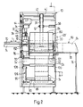
- FIGS. 1 and 2 A device for forming printed product packages with a holding element running around the roll of printed products will now be explained with reference to FIGS. 1 and 2.
- the device mentioned has a frame designated by 10, in which two belt conveyors 12 and 14 are arranged one behind the other.
- the first belt conveyor 12 which is only partially shown, is used to feed the printed products 16 which are to be wound up into a roll and accumulate in scale formation S to a winding point 18.
- the conveying direction of the belt conveyor 12 driven in rotation is designated by B in FIG. 1.
- each printed product 16 lies on the subsequent printed product. This means that the leading edges 16a of the printed products 16 lie in the scaly formation S that is fed in on the underside thereof.
- the second belt conveyor 14 is arranged in a carriage 20, which is supported by means of two guide rods 22, only one is visible in FIG.
- a cylindrical winding mandrel 30 which is freely rotatably mounted on a pivot lever 32, which in turn is pivotably seated on a shaft 34.
- the pivot lever 32 and with this the winding mandrel 30 can be pivoted in the direction of arrow D (FIG. 1).
- the pivot lever 32 and the winding mandrel 30 is shown with solid lines in its lower pivot position, while the upper pivot position of the pivot lever 32 and the winding mandrel 30 is dot-dash and designated 32 'and 30'. In its lower pivot position, the pivot lever 32 is in contact with a stop 36.
- the winding device also includes an endless belt 38 which is guided over a number of deflection rollers 40-52.
- the deflection rollers 40, 42, 44 and 48 are fixed in the frame 10
- the deflection rollers 49 and 50 are mounted in the carriage 20, while the deflection rollers 46 and 52 are pivotally mounted.
- the deflection roller 46 is mounted on one end of a lever 54 which is pivotally and clockwise biased on a shaft 56 at the other end, the longitudinal axis of which coincides with the axis of rotation of the deflection roller 48.
- the lever 54 and with this the deflection roller 46 can reciprocate in the direction of the arrow E (FIG. 1) swing.
- One end position of the lever 54 and roller 46 is shown with solid lines, while the other end position is shown with dash-dotted lines and is denoted by 54 'and 46'.
- the deflecting roller 52 is mounted at one end of a two-armed lever 58 which is pivotably mounted about a shaft 60 arranged on the frame 10 in the direction of the arrow F (FIG. 1).
- a cylinder-piston unit 62 engages, which pivots the lever 58 together with the deflection roller 52 into the upper end position 58 ', 52' shown with solid lines.
- the lower end position of the lever 58 and the deflection roller 52 is shown in broken lines.
- the deflection roller 40 is driven clockwise by the drive unit 64, so that the belt 38 is driven in a rotating manner in the direction of the arrow G (FIG. 1).
- a friction drive 66 drives the belt conveyor 14 in the active position shown in phantom in the direction of arrow H (FIG. 1).
- a plate-shaped ejector 68 which is fastened to one end of a rod 70 which is guided in a guide bearing 72 in the direction of the arrow L (FIG. 2) so as to be displaceable.
- a cylinder-piston unit 74 acts thereon (FIG. 2).
- the fully extended position of the ejector 68 is shown in broken lines and designated 68 '.
- a support table 78 is additionally arranged on the frame 10 by means of a support 76. The finished ones come out on him printed product packages 80 to the edition.
- a delivery device 82 for holding elements 84 opens into the movement path of the scale formation S.
- the holding element 84 is indicated by dash-dotted lines on the finished printed product package 80 in FIG. 2.
- Two parallel unwinding rollers 86, 88 are rotatably mounted on the frame 10, the unwinding roller 88 being operatively connected to a roller 92 by means of a chain 90.
- a supply roll 94 is placed, the film 94 'around which is fixed on the frame 10 and rotatably mounted deflection rolls 96, 98 and 100 to the roller 92 and one of these downstream belt conveyor 102.
- the film 94 ' is wound up in the supply roll 94 on a winding core 104, which comes to rest in the fully unwound state on the two unwinding rolls 86, 88, as shown in broken lines.
- the roller 92 is mounted on a shaft 114 and coupled to one side of a magnetic coupling 115.
- the roller 92 is operatively connected to the chain 90, while another chain 116, which is connected to the belt conveyor 102 is operatively connected, can be brought into operative connection with the roller 92 by means of the magnetic coupling 115.
- a brake unit 118 is also supported on the frame 10, the brake head 120 of which can be brought into braking action on the roller 92.
- Another roller 122 acts on the outside of the film 94 'guided around the roller 92. It is mounted on a pivotable and against the film 94 'biased frame 124, and it can only turn in the feed direction K of the film 94' due to a freewheel arranged therein, while an opposite rotation is prevented by the freewheel.
- the belt conveyor 102 has an endless belt 130 guided around two fixed rollers 126 and 128, on the conveyor-effective strand of which the film 94 'bears.
- a plurality of belts running parallel to one another can also be present instead of one belt 130.
- the roller 126 is operatively connected to a conveyor roller 134 which is also rotatably mounted on the frame 10.
- the conveyor roller 134 bears against the friction drive 66, as a result of which the latter is also rotated.
- the conveyor roller 134 is driven by the drive unit 64 by means of a drive chain 136.
- a cutting device 138 is pivotally mounted, which can be pivoted by means of a further cylinder-piston unit 140 from a rest position shown in solid lines to a cutting position shown in broken lines.
- the cutting device 138 is described in more detail with the aid of FIGS. 1 and 3.
- a lever arm 144 is pivotally mounted, on the free end of which the cylinder-piston unit 140 engages.
- a bracket 146 extending parallel to the axis of the pivot pins 142 is attached to the lever arm, at the ends of which a leaf spring 148 is arranged.
- Insulating bodies 150 are provided on the free ends of the leaf springs 148, to which holding pins 152 are fastened.
- a heating wire 154 is stretched between the holding pins 152 and is wound around the holding pins 152 at both ends.
- the connecting wires for the power supply for heating the heating wire 154 are denoted by 156. 3
- the rest position of the cutting device 138 is shown with solid lines, the heating wire 154 having expanded as a result of the heat.
- it contracts so that the ends of the leaf springs 148 come closer to one another, which is shown by dash-dotted lines, which are designated by 148 '(Fig. 3).
- the heating wire 154 is located in the region of the conveyor roller 134 and is shown when it is pivoted into the cutting position, shown in broken lines, through the film 94 'between the belt conveyor 102 and the conveyor roller 134.
- the film section fed to the winding point 18 is separated from the film 94 '.
- This separated film section serves as a holding element 84.
- the cutting device 138 pivots back into the rest position.
- the operation of the device for producing portable, tubular Print product packages 80 consisting of printed products 16 wound into a roll, fed in scale formation S, and a holding element 84 running around the roll for holding the roll together.
- the functioning of the delivery device 82 for the holding element 84 is initially specified.
- the conveyor roller 134 and the roller 126 of the belt conveyor 102 are driven in a clockwise direction, so that the conveyor-effective strand of the belt 130 moves in the direction of the arrow K. If no foil section serving as a holding element 84 is to be fed to the winding point 18, the magnetic coupling 115 is released and the roller 92 is prevented from rotating due to the extended brake head 120 of the brake unit 118.
- the film 94 ' Since the film 94 'is clamped against the roller 92 by the further roller 122 biased against it, the film 94' cannot advance in the direction of the arrow K. The end portion of the film 94 'extending from the roller 92 to the area of the heating wire 154' thus slidably abuts the conveyor-effective strand of the belt conveyor 102. Since the chain 90 is also decoupled from the chain 116 as a result of the magnetic coupling 115 being released, the supply roll 94 cannot rotate, and as a result of the weight lever 106, the film is stretched between the supply roll 94 and the roller 92.
- the brake head 120 is lifted off the roller 92 by means of the brake unit 118 and the magnetic clutch 115 is activated.
- the free running of the roller 122 prevents the film 94 'from running back against the direction of the arrow K.
- the roller 92 begins to rotate clockwise, so that free end of the film 94 'in the direction of the arrow K and H of the winding point 18 is supplied.
- the unwinding speed from the supply roller 94 is lower than the speed at which the film 94 'is conveyed from the roller 92 to the belt conveyor 102.
- This extension can be maintained with the aid of the belt conveyor 102 and the conveyor roller 134 up to the winding point 118.
- the film 94 ' is an elastic plastic that responds to this extension with a tensile force, which gives the roll of printed products 16 wrapped around it a good hold.
- the magnetic coupling 115 is released, and the free running of the roller 122 prevents movement of the film 94' against the direction of the arrow K.
- the roller 92 is braked by means of the brake unit 118, whereby the supply roll 94 also comes to a standstill.
- the belt conveyor 102 continues to move, so that the extension of the part of the film 94 'resting on it remains'.
- the film 94 ' is separated by means of the heated heating wire 154 from the winding 18 supplied section.
- the cutting device 138 pivots back into the rest position.
- the pivot lever 32 with the winding mandrel 30 is in the lower position, shown in solid lines, while the deflection roller 52 is shown in dash-dotted lines and Deflection roller 46 assumes the end position shown with solid lines.
- the belt 38 now runs from the deflection roller 40 via the deflection rollers 42 and 44 to the deflection roller 46, from this in turn via the deflection roller 44 to the deflection roller 48.
- the belt 38 runs around the deflection roller 49 and along the belt conveyor belt located below 14 up to the deflection roller 50 and then parallel to the upper run to the winding mandrel 30, which is wrapped around by the belt 38 along part of its circumference, and then continuously via the deflection roller 52 to the deflection roller 40.
- the belt 38 is shown partly in dash-dot lines.
- the scale formation S fed by the belt conveyor 12 passes over the roller 128 of the belt conveyor 102 and the conveyor roller 134 on the second belt conveyor 14 and the belt 38 to the winding mandrel 30, which is driven by the belt 38 in the counterclockwise direction.
- the supplied scale formation S is wound between the mandrel 30 and the belt 38 lying on the mandrel 30.
- the winding mandrel 30 With increasing radius of the formed product roll, which rests on the belt conveyor 14, the winding mandrel 30 is raised and pivoted upward about the pivot axis defined by the shaft 34 in the direction of arrow D, as shown in broken lines in FIG. 1.
- the lever 54 pivots with the deflection roller 46 in the counterclockwise direction from the position labeled 54 or 46 in the direction of arrow E against the end position labeled 54 'or 46'.
- the free end of the film 94 ' together with these printed products 16 of the winding 18 is supplied. Since the printed products 16 come to rest on the film 94 ', the part of the film section trailing the shingled stream S envelops after winding, the roll formed on the winding mandrel 30 from printed products 16.
- the film becomes 94 'severed.
- the two-armed lever 58 is pivoted back by means of the cylinder-piston unit 62 into the position denoted by 58 ', and at the same time the cylinder-piston unit 28 pulls the carriage 20 back from the position shown in broken lines to the position shown in solid lines.
- the printed product package 80 rolls off the belt conveyor 14 and pivots from the position shown in broken lines in the direction of arrow D into the lower end position defined by solid lines and by the stop 36.
- the winding mandrel 30 pivots back into the effective area of the ejector 68, which, by activating the cylinder-piston unit 74, pushes the finished printed product package 80 off the winding mandrel and conveys it to the support table 78 and is immediately pulled back into the starting position.
- the device By pushing the carriage 20 again into the position shown in dash-dotted lines and the two-armed lever 58 into the position 58, also indicated by dashed lines, the device is ready for the production of a further printed product package 80.
- supply roll 94 can be braked by other means than the chain 90 and the unwind roll 88, e.g. by a brake acting on the peripheral surface of the supply roll.
- film sections are separated from the supply roll 94 before they are fed to the movement path of the scale formation S and thus to the winding point 18.
- the holding element is preferably a transparent plastic film 94 'with self-adhesive properties.
Landscapes
- Mechanical Engineering (AREA)
- Engineering & Computer Science (AREA)
- Auxiliary Devices For And Details Of Packaging Control (AREA)
- Discharge By Other Means (AREA)
- Winding Of Webs (AREA)
- Medicines Containing Antibodies Or Antigens For Use As Internal Diagnostic Agents (AREA)
- Luminescent Compositions (AREA)
- Preparation Of Compounds By Using Micro-Organisms (AREA)
- Containers And Plastic Fillers For Packaging (AREA)
- Packaging Of Special Articles (AREA)
- Supplying Of Containers To The Packaging Station (AREA)
- Shaping Of Tube Ends By Bending Or Straightening (AREA)
- Packging For Living Organisms, Food Or Medicinal Products That Are Sensitive To Environmental Conditiond (AREA)
- Tubes (AREA)
- Replacement Of Web Rolls (AREA)
Priority Applications (1)
| Application Number | Priority Date | Filing Date | Title |
|---|---|---|---|
| AT88114902T ATE54885T1 (de) | 1987-10-21 | 1988-09-13 | Vorrichtung zum herstellen von tragbaren, rohrfoermigen paketen aus druckprodukten. |
Applications Claiming Priority (2)
| Application Number | Priority Date | Filing Date | Title |
|---|---|---|---|
| CH4115/87 | 1987-10-21 | ||
| CH411587 | 1987-10-21 |
Publications (3)
| Publication Number | Publication Date |
|---|---|
| EP0313781A2 true EP0313781A2 (fr) | 1989-05-03 |
| EP0313781A3 EP0313781A3 (en) | 1989-09-20 |
| EP0313781B1 EP0313781B1 (fr) | 1990-07-25 |
Family
ID=4270093
Family Applications (1)
| Application Number | Title | Priority Date | Filing Date |
|---|---|---|---|
| EP88114902A Expired - Lifetime EP0313781B1 (fr) | 1987-10-21 | 1988-09-13 | Dispositif pour la fabrication de paquets portables tubulaires de produits d'imprimerie |
Country Status (9)
| Country | Link |
|---|---|
| US (1) | US4909015A (fr) |
| EP (1) | EP0313781B1 (fr) |
| JP (1) | JP2657834B2 (fr) |
| AT (1) | ATE54885T1 (fr) |
| AU (1) | AU601310B2 (fr) |
| CA (1) | CA1301625C (fr) |
| DE (1) | DE3860365D1 (fr) |
| FI (1) | FI87439C (fr) |
| RU (1) | RU1836278C (fr) |
Cited By (2)
| Publication number | Priority date | Publication date | Assignee | Title |
|---|---|---|---|---|
| EP0588758A1 (fr) * | 1992-09-15 | 1994-03-23 | Ferag AG | Procédé et dispositif de fabrication de paquets tubulaires d'articles imprimés munis d'une bande de déchirement |
| US5617704A (en) * | 1992-09-15 | 1997-04-08 | Ferag Ag | Method of forming a tubular pack of printed products with a transparent foil cover |
Families Citing this family (10)
| Publication number | Priority date | Publication date | Assignee | Title |
|---|---|---|---|---|
| NL9002246A (nl) * | 1990-08-28 | 1992-03-16 | Ferag Ag | Werkwijze voor het verwerken van in een schubbenformatie beschikbaar komend drukwerk. |
| AU656578B2 (en) * | 1991-05-14 | 1995-02-09 | Ferag Ag | Pressing device for winding machines for producing tubular packs of printed products |
| DE59306228D1 (de) * | 1992-03-19 | 1997-05-28 | Ferag Ag | Verfahren und Vorrichtung zum Auf- und Abwinkeln von Druckprodukten in Schuppenformation |
| DK0568844T3 (da) * | 1992-05-05 | 1996-07-29 | Ferag Ag | Indretning til rulning af et trykkeriprodukt og omvikling af rullen med et indpakningselement |
| EP0618138B1 (fr) * | 1993-04-01 | 1997-06-04 | Ferag AG | Dispositif de formation de paquets tubulaires portables de produits imprimés |
| EP0618139B1 (fr) * | 1993-04-01 | 1997-06-04 | Ferag AG | Dispositif de traitement de produits imprimés |
| US5580012A (en) * | 1995-03-17 | 1996-12-03 | Moore Business Forms, Inc. | Shingled linerless label rolls |
| FR2953207B1 (fr) * | 2009-11-27 | 2011-12-30 | Michelin Rech Tech | Dispositif de manutention d'une bande de produit contenant de la gomme et procede de production d'un roule sur lequel est enroulee cette bande |
| CN102862843A (zh) * | 2012-09-26 | 2013-01-09 | 无锡市恒达矿山机械有限公司 | 一种便携式铝带收卷机 |
| US9950895B2 (en) | 2014-07-03 | 2018-04-24 | Lincoln Global, Inc. | Welding wire coil packaging system |
Citations (5)
| Publication number | Priority date | Publication date | Assignee | Title |
|---|---|---|---|---|
| DE86129C (fr) * | ||||
| DE1248536B (de) * | 1961-10-25 | 1967-08-24 | Toronto Star Ltd | Vorrichtung zum Wickeln und Packen von Zeitungen u. dgl. |
| FR2322051A1 (fr) * | 1975-08-26 | 1977-03-25 | Kuper Heinrich | Appareil a emballer des objets dans des feuilles |
| WO1985000576A1 (fr) * | 1983-07-15 | 1985-02-14 | A.H.R. Brookman Investments Pty. Ltd. | Machine a envelopper des journaux |
| EP0243906A1 (fr) * | 1986-05-02 | 1987-11-04 | Ferag AG | Procédé et dispositif pour faire des paquets tubulaires portatifs d'imprimés comme des journaux, des revues et similaires |
Family Cites Families (10)
| Publication number | Priority date | Publication date | Assignee | Title |
|---|---|---|---|---|
| CA689556A (en) * | 1964-06-30 | R. Sykes Thomas | Bundling apparatus | |
| CH652701A5 (de) * | 1981-02-03 | 1985-11-29 | Ferag Ag | Verfahren und einrichtung zur erzielung eines langzeitpressungseffekts bei druckprodukten, insbesondere zeitungen. |
| CH654553A5 (de) * | 1981-12-09 | 1986-02-28 | Ferag Ag | Verfahren und vorrichtung zum speichern von kontinuierlich, insbesondere in einem schuppenstrom, anfallenden flaechigen erzeugnissen, vorzugsweise druckprodukten. |
| CH656861A5 (de) * | 1982-06-14 | 1986-07-31 | Grapha Holding Ag | Vorrichtung zum lagern von papierbogen. |
| JPS596769A (ja) * | 1982-06-30 | 1984-01-13 | Fujitsu Ltd | 転動モ−タ |
| US4589603A (en) * | 1983-01-21 | 1986-05-20 | Grapha-Holding Ag | Apparatus for temporary storage of a stream of partially overlapping sheets |
| US4748793A (en) * | 1983-07-15 | 1988-06-07 | A. H. R. Brookman Investments Pty. Ltd. | Newspaper wrapping machine |
| CH670245A5 (fr) * | 1986-01-20 | 1989-05-31 | Ferag Ag | |
| EP0243837B1 (fr) * | 1986-04-30 | 1989-07-26 | Ferag AG | Procédé et dispositif pour traiter des produits imprimés comme des journaux, des magazines et similaires |
| EP0300742A3 (fr) * | 1987-07-20 | 1990-10-31 | Xerox Corporation | Appareil pour enrouler et enrubanner automatiquement des feuilles sortant d'un système de reproduction de documents |
-
1988
- 1988-09-13 AT AT88114902T patent/ATE54885T1/de not_active IP Right Cessation
- 1988-09-13 DE DE8888114902T patent/DE3860365D1/de not_active Expired - Fee Related
- 1988-09-13 EP EP88114902A patent/EP0313781B1/fr not_active Expired - Lifetime
- 1988-10-14 RU SU884356583A patent/RU1836278C/ru active
- 1988-10-18 US US07/259,562 patent/US4909015A/en not_active Expired - Fee Related
- 1988-10-19 AU AU23999/88A patent/AU601310B2/en not_active Ceased
- 1988-10-19 CA CA000580605A patent/CA1301625C/fr not_active Expired - Fee Related
- 1988-10-20 FI FI884857A patent/FI87439C/fi not_active IP Right Cessation
- 1988-10-21 JP JP63265973A patent/JP2657834B2/ja not_active Expired - Lifetime
Patent Citations (5)
| Publication number | Priority date | Publication date | Assignee | Title |
|---|---|---|---|---|
| DE86129C (fr) * | ||||
| DE1248536B (de) * | 1961-10-25 | 1967-08-24 | Toronto Star Ltd | Vorrichtung zum Wickeln und Packen von Zeitungen u. dgl. |
| FR2322051A1 (fr) * | 1975-08-26 | 1977-03-25 | Kuper Heinrich | Appareil a emballer des objets dans des feuilles |
| WO1985000576A1 (fr) * | 1983-07-15 | 1985-02-14 | A.H.R. Brookman Investments Pty. Ltd. | Machine a envelopper des journaux |
| EP0243906A1 (fr) * | 1986-05-02 | 1987-11-04 | Ferag AG | Procédé et dispositif pour faire des paquets tubulaires portatifs d'imprimés comme des journaux, des revues et similaires |
Cited By (2)
| Publication number | Priority date | Publication date | Assignee | Title |
|---|---|---|---|---|
| EP0588758A1 (fr) * | 1992-09-15 | 1994-03-23 | Ferag AG | Procédé et dispositif de fabrication de paquets tubulaires d'articles imprimés munis d'une bande de déchirement |
| US5617704A (en) * | 1992-09-15 | 1997-04-08 | Ferag Ag | Method of forming a tubular pack of printed products with a transparent foil cover |
Also Published As
| Publication number | Publication date |
|---|---|
| RU1836278C (ru) | 1993-08-23 |
| FI884857A0 (fi) | 1988-10-20 |
| EP0313781A3 (en) | 1989-09-20 |
| FI884857A (fi) | 1989-04-22 |
| DE3860365D1 (de) | 1990-08-30 |
| US4909015A (en) | 1990-03-20 |
| JP2657834B2 (ja) | 1997-09-30 |
| ATE54885T1 (de) | 1990-08-15 |
| AU2399988A (en) | 1989-04-27 |
| FI87439C (fi) | 1993-01-11 |
| EP0313781B1 (fr) | 1990-07-25 |
| AU601310B2 (en) | 1990-09-06 |
| FI87439B (fi) | 1992-09-30 |
| CA1301625C (fr) | 1992-05-26 |
| JPH01145974A (ja) | 1989-06-07 |
Similar Documents
| Publication | Publication Date | Title |
|---|---|---|
| DE3123888C2 (de) | Vorrichtung zum Zwischenspeichern von in Schuppenformation anfallenden Zeitungen, Zeitschriften oder dergleichen | |
| DE69919493T2 (de) | Oberflächenwickler mit Klemmschneider | |
| DE3217628C2 (de) | Verfahren sowie eine Vorrichtung zum Aufwickeln je eines Abschnittes von mehreren auf einander folgenden Abschnitten einer endlosen Material-Bahn | |
| EP0243906B1 (fr) | Procédé et dispositif pour faire des paquets tubulaires portatifs d'imprimés comme des journaux, des revues et similaires | |
| DE3221153C2 (fr) | ||
| DE3225518A1 (de) | Verfahren und vorrichtung fuer das abreissen von bahnenfoermigem material | |
| CH652699A5 (de) | Einrichtung zum speichern von in einer schuppenformation anfallenden flaechigen erzeugnissen, insbesondere druckprodukten. | |
| DE3811138A1 (de) | Verfahren und vorrichtung zum behandeln des endabschnitts von aufgerolltem papier | |
| EP1453750B1 (fr) | Dispositif pour la production de rouleaux de film | |
| EP0968919B1 (fr) | Procédé et dispositif d'enveloppement d'objets quadrangulaires avec un matériau d'emballage sous forme de bande | |
| DE2600522C2 (fr) | ||
| DE3902454A1 (de) | Einrichtung zum auftrennen und entfernen eines verpackungsmateriales | |
| EP0313781B1 (fr) | Dispositif pour la fabrication de paquets portables tubulaires de produits d'imprimerie | |
| DE4342277C2 (de) | Revolverkopf-Tragwalzenwickler | |
| DE2658294A1 (de) | Vorrichtung zum abwickeln von aus ventilsaecken bestehenden schuppenbandrollen | |
| DE4428786A1 (de) | Vorrichtung zur Entnahme von Spulen aus einem Magazin und zur Übertragung derselben an eine Abwickeleinheit | |
| DE19533086A1 (de) | Verfahren und Vorrichtung zum Stapeln von flächigen Erzeugnissen, insbesondere Druckereiprodukten | |
| DE4016484C2 (de) | Verpackungsvorrichtung für Bahnrollen | |
| EP0135080B1 (fr) | Dispositif pour enrouler une pluralité de feuilles imprimées | |
| EP0568844B1 (fr) | Dispositif et méthode pour enrouler un produit de l'imprimerie et pour envelopper le rouleau avec une enveloppe | |
| DE4029914A1 (de) | Tragwalzen-wickelmaschine | |
| DE2844519C2 (fr) | ||
| EP0618139B1 (fr) | Dispositif de traitement de produits imprimés | |
| DE3619939A1 (de) | Verfahren und vorrichtung zum zwischenspeichern von in schuppenformation anfallenden druckprodukten | |
| EP0618138B1 (fr) | Dispositif de formation de paquets tubulaires portables de produits imprimés |
Legal Events
| Date | Code | Title | Description |
|---|---|---|---|
| PUAI | Public reference made under article 153(3) epc to a published international application that has entered the european phase |
Free format text: ORIGINAL CODE: 0009012 |
|
| AK | Designated contracting states |
Kind code of ref document: A2 Designated state(s): AT CH DE FR GB IT LI NL SE |
|
| PUAL | Search report despatched |
Free format text: ORIGINAL CODE: 0009013 |
|
| AK | Designated contracting states |
Kind code of ref document: A3 Designated state(s): AT CH DE FR GB IT LI NL SE |
|
| 17P | Request for examination filed |
Effective date: 19891005 |
|
| 17Q | First examination report despatched |
Effective date: 19891220 |
|
| GRAA | (expected) grant |
Free format text: ORIGINAL CODE: 0009210 |
|
| ITF | It: translation for a ep patent filed |
Owner name: BARZANO' E ZANARDO MILANO S.P.A. |
|
| AK | Designated contracting states |
Kind code of ref document: B1 Designated state(s): AT CH DE FR GB IT LI NL SE |
|
| REF | Corresponds to: |
Ref document number: 54885 Country of ref document: AT Date of ref document: 19900815 Kind code of ref document: T |
|
| ET | Fr: translation filed | ||
| REF | Corresponds to: |
Ref document number: 3860365 Country of ref document: DE Date of ref document: 19900830 |
|
| GBT | Gb: translation of ep patent filed (gb section 77(6)(a)/1977) | ||
| PLBE | No opposition filed within time limit |
Free format text: ORIGINAL CODE: 0009261 |
|
| STAA | Information on the status of an ep patent application or granted ep patent |
Free format text: STATUS: NO OPPOSITION FILED WITHIN TIME LIMIT |
|
| 26N | No opposition filed | ||
| ITTA | It: last paid annual fee | ||
| EAL | Se: european patent in force in sweden |
Ref document number: 88114902.5 |
|
| PGFP | Annual fee paid to national office [announced via postgrant information from national office to epo] |
Ref country code: NL Payment date: 19960815 Year of fee payment: 9 |
|
| PGFP | Annual fee paid to national office [announced via postgrant information from national office to epo] |
Ref country code: AT Payment date: 19960821 Year of fee payment: 9 |
|
| PGFP | Annual fee paid to national office [announced via postgrant information from national office to epo] |
Ref country code: FR Payment date: 19960827 Year of fee payment: 9 |
|
| PG25 | Lapsed in a contracting state [announced via postgrant information from national office to epo] |
Ref country code: AT Free format text: LAPSE BECAUSE OF NON-PAYMENT OF DUE FEES Effective date: 19970913 |
|
| PG25 | Lapsed in a contracting state [announced via postgrant information from national office to epo] |
Ref country code: FR Free format text: THE PATENT HAS BEEN ANNULLED BY A DECISION OF A NATIONAL AUTHORITY Effective date: 19970930 |
|
| PG25 | Lapsed in a contracting state [announced via postgrant information from national office to epo] |
Ref country code: NL Free format text: LAPSE BECAUSE OF NON-PAYMENT OF DUE FEES Effective date: 19980401 |
|
| NLV4 | Nl: lapsed or anulled due to non-payment of the annual fee |
Effective date: 19980401 |
|
| REG | Reference to a national code |
Ref country code: FR Ref legal event code: ST |
|
| REG | Reference to a national code |
Ref country code: GB Ref legal event code: IF02 |
|
| PGFP | Annual fee paid to national office [announced via postgrant information from national office to epo] |
Ref country code: GB Payment date: 20040907 Year of fee payment: 17 |
|
| REG | Reference to a national code |
Ref country code: CH Ref legal event code: PFA Owner name: FERAG AG Free format text: FERAG AG#ZUERICHSTRASSE 74#8340 HINWIL (CH) -TRANSFER TO- FERAG AG#PATENTABTEILUNG Z. H. MARKUS FELIX ZUERICHSTRASSE 74#8340 HINWIL (CH) |
|
| PG25 | Lapsed in a contracting state [announced via postgrant information from national office to epo] |
Ref country code: IT Free format text: LAPSE BECAUSE OF NON-PAYMENT OF DUE FEES;WARNING: LAPSES OF ITALIAN PATENTS WITH EFFECTIVE DATE BEFORE 2007 MAY HAVE OCCURRED AT ANY TIME BEFORE 2007. THE CORRECT EFFECTIVE DATE MAY BE DIFFERENT FROM THE ONE RECORDED. Effective date: 20050913 Ref country code: GB Free format text: LAPSE BECAUSE OF NON-PAYMENT OF DUE FEES Effective date: 20050913 |
|
| GBPC | Gb: european patent ceased through non-payment of renewal fee |
Effective date: 20050913 |
|
| PGFP | Annual fee paid to national office [announced via postgrant information from national office to epo] |
Ref country code: CH Payment date: 20060830 Year of fee payment: 19 |
|
| PGFP | Annual fee paid to national office [announced via postgrant information from national office to epo] |
Ref country code: DE Payment date: 20060926 Year of fee payment: 19 |
|
| PGFP | Annual fee paid to national office [announced via postgrant information from national office to epo] |
Ref country code: SE Payment date: 20060914 Year of fee payment: 19 |
|
| PG25 | Lapsed in a contracting state [announced via postgrant information from national office to epo] |
Ref country code: SE Free format text: LAPSE BECAUSE OF NON-PAYMENT OF DUE FEES Effective date: 20070914 |
|
| REG | Reference to a national code |
Ref country code: CH Ref legal event code: PL |
|
| EUG | Se: european patent has lapsed | ||
| PG25 | Lapsed in a contracting state [announced via postgrant information from national office to epo] |
Ref country code: LI Free format text: LAPSE BECAUSE OF NON-PAYMENT OF DUE FEES Effective date: 20070930 Ref country code: DE Free format text: LAPSE BECAUSE OF NON-PAYMENT OF DUE FEES Effective date: 20080401 Ref country code: CH Free format text: LAPSE BECAUSE OF NON-PAYMENT OF DUE FEES Effective date: 20070930 |