EP0100462A2 - Web winding device - Google Patents
Web winding device Download PDFInfo
- Publication number
- EP0100462A2 EP0100462A2 EP83106705A EP83106705A EP0100462A2 EP 0100462 A2 EP0100462 A2 EP 0100462A2 EP 83106705 A EP83106705 A EP 83106705A EP 83106705 A EP83106705 A EP 83106705A EP 0100462 A2 EP0100462 A2 EP 0100462A2
- Authority
- EP
- European Patent Office
- Prior art keywords
- winding
- winder
- web
- clamping head
- holder
- Prior art date
- Legal status (The legal status is an assumption and is not a legal conclusion. Google has not performed a legal analysis and makes no representation as to the accuracy of the status listed.)
- Granted
Links
- 238000004804 winding Methods 0.000 title claims abstract description 118
- 239000004744 fabric Substances 0.000 claims abstract description 52
- 238000011144 upstream manufacturing Methods 0.000 claims abstract description 5
- 230000008878 coupling Effects 0.000 claims description 27
- 238000010168 coupling process Methods 0.000 claims description 27
- 238000005859 coupling reaction Methods 0.000 claims description 27
- 230000006835 compression Effects 0.000 claims description 8
- 238000007906 compression Methods 0.000 claims description 8
- 238000006073 displacement reaction Methods 0.000 claims description 7
- 239000000463 material Substances 0.000 claims description 5
- 238000000034 method Methods 0.000 description 4
- 230000004048 modification Effects 0.000 description 4
- 238000012986 modification Methods 0.000 description 4
- 230000008569 process Effects 0.000 description 4
- 239000002985 plastic film Substances 0.000 description 2
- 229920006255 plastic film Polymers 0.000 description 2
- 238000000926 separation method Methods 0.000 description 2
- 230000001960 triggered effect Effects 0.000 description 2
- 230000037303 wrinkles Effects 0.000 description 2
- 230000015572 biosynthetic process Effects 0.000 description 1
- 230000008859 change Effects 0.000 description 1
- 230000000694 effects Effects 0.000 description 1
- 210000003608 fece Anatomy 0.000 description 1
- 238000003780 insertion Methods 0.000 description 1
- 230000037431 insertion Effects 0.000 description 1
- 239000010871 livestock manure Substances 0.000 description 1
- 210000004072 lung Anatomy 0.000 description 1
- 238000005554 pickling Methods 0.000 description 1
- 230000001360 synchronised effect Effects 0.000 description 1
Images


Classifications
-
- B—PERFORMING OPERATIONS; TRANSPORTING
- B65—CONVEYING; PACKING; STORING; HANDLING THIN OR FILAMENTARY MATERIAL
- B65H—HANDLING THIN OR FILAMENTARY MATERIAL, e.g. SHEETS, WEBS, CABLES
- B65H19/00—Changing the web roll
- B65H19/22—Changing the web roll in winding mechanisms or in connection with winding operations
- B65H19/2207—Changing the web roll in winding mechanisms or in connection with winding operations the web roll being driven by a winding mechanism of the centre or core drive type
- B65H19/2215—Turret-type with two roll supports
-
- B—PERFORMING OPERATIONS; TRANSPORTING
- B65—CONVEYING; PACKING; STORING; HANDLING THIN OR FILAMENTARY MATERIAL
- B65H—HANDLING THIN OR FILAMENTARY MATERIAL, e.g. SHEETS, WEBS, CABLES
- B65H2301/00—Handling processes for sheets or webs
- B65H2301/40—Type of handling process
- B65H2301/41—Winding, unwinding
- B65H2301/413—Supporting web roll
- B65H2301/4134—Both ends type arrangement
- B65H2301/41346—Both ends type arrangement separate elements engaging each end of the roll (e.g. chuck)
-
- B—PERFORMING OPERATIONS; TRANSPORTING
- B65—CONVEYING; PACKING; STORING; HANDLING THIN OR FILAMENTARY MATERIAL
- B65H—HANDLING THIN OR FILAMENTARY MATERIAL, e.g. SHEETS, WEBS, CABLES
- B65H2301/00—Handling processes for sheets or webs
- B65H2301/40—Type of handling process
- B65H2301/41—Winding, unwinding
- B65H2301/414—Winding
- B65H2301/4143—Performing winding process
- B65H2301/41432—Performing winding process special features of winding process
- B65H2301/414326—Performing winding process special features of winding process winding on core with non-circular cross-sectional profile, e.g. polygonal, oval, flat or slightly curved
-
- B—PERFORMING OPERATIONS; TRANSPORTING
- B65—CONVEYING; PACKING; STORING; HANDLING THIN OR FILAMENTARY MATERIAL
- B65H—HANDLING THIN OR FILAMENTARY MATERIAL, e.g. SHEETS, WEBS, CABLES
- B65H2301/00—Handling processes for sheets or webs
- B65H2301/40—Type of handling process
- B65H2301/41—Winding, unwinding
- B65H2301/417—Handling or changing web rolls
- B65H2301/4171—Handling web roll
- B65H2301/41745—Handling web roll by axial movement of roll
-
- B—PERFORMING OPERATIONS; TRANSPORTING
- B65—CONVEYING; PACKING; STORING; HANDLING THIN OR FILAMENTARY MATERIAL
- B65H—HANDLING THIN OR FILAMENTARY MATERIAL, e.g. SHEETS, WEBS, CABLES
- B65H2301/00—Handling processes for sheets or webs
- B65H2301/40—Type of handling process
- B65H2301/41—Winding, unwinding
- B65H2301/417—Handling or changing web rolls
- B65H2301/418—Changing web roll
- B65H2301/4185—Core or mandrel discharge or removal, also organisation of core removal
- B65H2301/41852—Core or mandrel discharge or removal, also organisation of core removal by extracting mandrel from wound roll, e.g. in coreless applications
-
- B—PERFORMING OPERATIONS; TRANSPORTING
- B65—CONVEYING; PACKING; STORING; HANDLING THIN OR FILAMENTARY MATERIAL
- B65H—HANDLING THIN OR FILAMENTARY MATERIAL, e.g. SHEETS, WEBS, CABLES
- B65H2408/00—Specific machines
- B65H2408/20—Specific machines for handling web(s)
- B65H2408/23—Winding machines
- B65H2408/231—Turret winders
- B65H2408/2315—Turret winders specified by number of arms
- B65H2408/23152—Turret winders specified by number of arms with two arms
-
- B—PERFORMING OPERATIONS; TRANSPORTING
- B65—CONVEYING; PACKING; STORING; HANDLING THIN OR FILAMENTARY MATERIAL
- B65H—HANDLING THIN OR FILAMENTARY MATERIAL, e.g. SHEETS, WEBS, CABLES
- B65H2701/00—Handled material; Storage means
- B65H2701/10—Handled articles or webs
- B65H2701/17—Nature of material
- B65H2701/174—Textile, fibre
-
- F—MECHANICAL ENGINEERING; LIGHTING; HEATING; WEAPONS; BLASTING
- F02—COMBUSTION ENGINES; HOT-GAS OR COMBUSTION-PRODUCT ENGINE PLANTS
- F02B—INTERNAL-COMBUSTION PISTON ENGINES; COMBUSTION ENGINES IN GENERAL
- F02B3/00—Engines characterised by air compression and subsequent fuel addition
- F02B3/06—Engines characterised by air compression and subsequent fuel addition with compression ignition
Definitions
- the invention relates to a winding device for webs with two winders, which are equipped with winding holders that can be attached to both sides of the web and are mounted together with an upstream deflecting element in an axially parallel manner on a rotatable console and can exchange their position by pivoting the console through 180 ° and alternately in a winding position a commenced winding are operated starting done by wrapping and in a waiting position a new roll, and with an independently supported by the console T racing device on a web section between the be: acting the winders, and in which the web of the deflecting element in each degree of filling partially wrapping the resulting winding and then only being brought into contact with the resulting winding after this wrapping,
- Such a winding device for plastic films is known from DE-AS 2 317 325, in which a tube as a winding core is clamped between the two winding holders of a winder, on which the plastic film is then wound.
- a pressure roller rests on the cut of the film web and presses it against the winding core until this cut sits firmly on the winding core.
- Such a pressure roller causes wrinkles in the winding in the case of webs which tend to form folds, as is the case in particular in the case of doubled and multilayered cloth webs, which are undesirable.
- the object of the invention is to design a device of the type mentioned above so that even with manure to F alternatebil- sloping webs such wrinkles are avoided if possible, especially if flat coils are wound on winding cores brettchenförmige. In doing so, forced breaks at the start of a new winding should be shortened as much as possible.
- the invention is characterized in that the web of material is guided tensioned between the winding holders of the winder in the waiting position and to the winder in the winding position.
- the winding supports are equipped with clamping elements, in that the winding support by axial displacement from a remote position adjacent the web, they in W artestel- lung occupy the associated winder, are adjustable in an attached position in which the clamping elements together with the edge of the web of a grasp the inserted winding core and clamp it and take it in during winding, and that an anti-rotation device is provided for each reel holder, with which the associated clamping elements are locked in the waiting position in a rotational position in which they are aligned with the plane of the web being passed.
- the material web is clamped only at its edges in the spread tension in which it is kept ready, the ends of the winding core being clamped at the same time. This maintains the tension, even in the individual layers of a doubled or multi-layered sheet, so that, as experience has shown, undesirable wrinkling can be avoided.
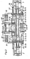
- 1 denotes the machine frame, on which a bracket shaft 5, which is rotatably mounted about the bracket axis 4, is mounted in two pivot bearings 2 and 3.
- Two brackets 6, 7 are mounted on the bracket shaft 5 so as to be longitudinally displaceable but torsionally rigid.
- the brackets can be moved on the bracket shaft 5 by rotating a handwheel which is mounted on the associated bracket and drives a pinion which engages in a rack which is fastened to the bracket shaft 5.
- the wheel 3 for the console 8. 7 The rack is designated 39.
- the rack also serves as an anti-rotation device for the console on the console shaft 5. By moving the consoles, the device is adapted to different widths of the fabric sheet 16.
- the brackets four winding holders 8, 9, 10, stored 1 1, of which the winding holders 8, 10 are arranged coaxially to the winder axis 1 2 and form the winder 13, while the winding holders 9 are disposed 1 1 coaxially to the winder axis 14 and form the winder 15.
- the winding holder 8, 9, 10, 11 are arranged in mutually facing sides of the brackets 6, 7 in pairs facing each other.
- the fabric web 16 shown in FIGS. 5 a to 5 c extends between the winding holders.
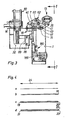
- the fabric web 16 can be simple, as shown in FIG. 4 a; twice, ie doubled, as shown in Figure 4 b; doubled, ie fourfold, as shown in Figure 4 d; placed three times, as shown in Figure 4 c or placed several times.
- the longitudinal fold along the longitudinal folds 18 to 23 serves to wind a wider cloth web according to FIGS. 4 b, c and d onto a winder 25 which is less wide according to the double arrow 24 in order to facilitate storage.
- the web of fabric 16 passes from the upstream machine 17 - apart from the longitudinal folds - into the winding device without any creases and is to be wound up by the winding device to form windings corresponding to the winding 25 and the formation of additional new folds, poses and the like is to be avoided.
- Drive motors 40, 41, 42, 43 assigned to the individual winding holders are used to drive the winders 13 and 15 and, as can be seen in FIGS. 2 and 3, are mounted on the respective console 6 and 7 in addition to the associated winding holders. Each winding holder is thus driven directly by the drive motor assigned to it.
- These drive motors drive clamping heads 44, 45, 46, 47 of the individual winding holders around the respective winding axis 12, 14 while rotating.
- the clamping heads 44, 45, 46, 47 are rotatably and longitudinally displaceable in the associated winding holder.
- the winding holders 8, 9, 10, 11 are of identical design and are arranged mirror-symmetrically to the plane of symmetry 58, which is perpendicular to the plane of the drawing in FIG. 1.
- the W ickelhalter a winder that is, for example, the winding holders 9, 11 of the winder 15, are operated jointly and synchronously. It is not absolutely necessary but expedient to provide a device for synchronizing the rotary movement.
- a coupling shaft 60 which is rotatably mounted on both brackets axially parallel to the winding axis 1 4, is used for the winding holder 9, 1 1 and is connected in a torsionally rigid manner to the two winding holders 9, 11.
- the corresponding coupling shaft for the winding holder 8, 10 is designated 61.
- the drive gear 35 of the drive motor 4 1 meshes with a drive gear 36 of the winding holder 10.
- the drive gear 35 also meshes with a deflection gear 37, which is torsionally rigid but axially displaceable on the clutch shaft 6 1 .
- the opposite winding holder 8 of the same winder 15 is synchronized by the rotational movement of the coupling shaft 61, and thus also by that of the winding holder 10 Deflection gear 1 1 4, which is torsionally rigid and axially displaceable on the coupling shaft 61 and meshes with the drive gear 115 of the drive motor 43.
- the Kupplun g swellen 60, 61 extend beyond the maximum distance of the two brackets 6, 7 and are axially displaceable in these, the L jossverschiebung'der consoles along the K onsolenwelle 5 not to interfere.
- each of these deflecting tubes for example the deflecting tube 63, compare FIG. 1 4, consists of two tube sections 64, 65 which are telescopically placed one above the other in pairs and of which one tube section 64 is fastened to one bracket 7 and the other tube section 65 to the other bracket 6 _is.
- the deflection tube 63 formed by the tube sections can thereby be telescopically pulled apart and plugged together and thus follows the distance between the brackets 6, 7 in its length.
- the deflection tube 63 is provided on its circumference with projecting ribs 67, which extend obliquely to the side in the conveying direction according to arrow 70 from the plane of symmetry 58 and thus from the center of the fabric web 16.
- the ribs each extend only over those outer parts of the tube sections 64, 65 which do not overlap when telescopically pushed together.
- the ribs 67 are, based on the axial direction of the associated deflection axis 7 1 , narrower according to double arrow 73 than 1/10 of the width according to double arrow 74 of the spaces 75, 76 to the adjacent ribs.
- the ribs 67 are formed by two spirals 77, 78.
- deflection rail that has a wrapping surface that is curved in the wrapping direction of the fabric web and that extends over the greatest wrapping angle that occurs.
- the ribs are advantageously provided, but can also be omitted.
- the deflection tube 63 is not rotatable. In a modification, however, the deflection tube 63 can be rotatably mounted about the deflection axis 7 1 , it can be driven to rotate about this axis and can be coupled to the drive of the associated winder for this purpose.
- the deflection tube 63 belongs to the winder 13.
- the deflection tube 6 2 which is designed correspondingly to the deflection tube 63, belongs to the winder 15.
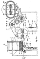
- a deflecting tube 62, 63 or a deflecting element is assigned to each of the winders and is arranged directly upwards of this associated winder.
- the deflection element is arranged in such a way that when the winding is filled to the maximum between the deflection element and the winding there is at least a tolerance distance 174 (see FIG. 5 a), so that the filled winding can rotate past the deflection element without problems.
- the deflection element is arranged so far offset that the tightly drawn web of cloth wrapped around the deflection element with a wrap angle 79 with filled winding of at least 1 0 °, so that the cloth strip 16 even at the maximum g e-for bottled winding not undesirable from the Umienkelement takes off and flutters. If the winding is less filled, as can be seen from FIG. 5 a, a larger wrap angle 79 then results.
- the fabric web 16 is only in contact with the resulting wrap. Following the deflecting element, the fabric web reaches the winding directly. It is wound up freely there and is not under the pressure load of a pressure roller, which loads from the outside on the winding being formed. Such a pressure roller would lead to undesirable wrinkling.
- a board magazine 80 is arranged, which is attached to the machine frame 1.
- the board magazine is ge with a stack of serving as winding cores 81 ge fills, of which the lowest board 82 in each case is released in the direction of arrow 84 with the aid of a distributor 83 assigned to the board magazine 80, whereupon the other boards move downward in the direction of arrow 85.
- the board magazine is adaptable to boards of different lengths according to the width of the fabric sheet 16 being processed.
- the allocator 83 places the dispensed board on the then idle cloth web 16 between the two winder holders 9, 11 of the winder 15 which is in the waiting position.
- the Brettchernmagazin 80 is adaptable to different widths of the cloth web.
- the two magazine cheeks 86, 87 are fastened to cheek supports 31, 32 which can be displaced transversely.
- the cheek beam 31 is mounted on a slide rod 91 and on a parallel threaded spindle 90 in the direction of the console axis 4.
- Threaded spindle 90 and slide rod 91 are mounted in end shields 28, 92 on the machine frame 1.
- the cheek carrier 32 is mounted accordingly.
- the associated hand crank is designated 27, the rod 89 and the threaded spindle 88.
- a separating device is arranged on a cross member 1 84.
- the cross member 184 is mounted on both sides of a hydraulic lifting cylinder 1 85, 186 adjustable in height on the machine frame 1.
- To the cross member 184 are on the cloth web width distributed rotatably drivable knife discs 1 87 disposed, whose circumference is in each case a polygon, and is formed as a cutting edge.
- the cutter discs 1 87 with their cutting a over the entire Tuchbahnoreite extending, horizontal, combined cutting edge, as indicated by the dash-dotted line 1 88 in FIG. 1 In the lower rest position shown in FIGS. 1 and 5, the separating device 180 is ineffective.
- the separating device 180 is arranged that, as can be seen particularly well from FIG. 5 a, it is effective immediately downward of the winder 15 which is in the waiting position.
- a drive sleeve 1 13 in ball bearings 03 1, 104 and a rotary sliding bearing 1 12 in the ball bearing 1 02 is rotatable but not longitudinally displaceably mounted.
- the bearing tube 1 07 is mounted for longitudinal displacement.
- a guide wedge is designated, which forces the bearing tube 107 to follow the rotational movements of the driving sleeve 113.
- the drive gear 36 is fastened on the driving sleeve 113.
- the bearing tube 1 07 there is a coupling element 121 which is longitudinally displaceably sliding.
- the push rod 154 of a sword 155 is mounted at the front end of the coupling element.
- the push rod 1 54 is flat and is longitudinally displaceable in a form-fitting longitudinal groove in the coupling element 121, and is supported to the rear on a compression spring 164.
- the longitudinal displacement is limited by an elongated hole 162 in the push rod 154 through which a pin 1 63 of the coupling element is inserted .
- the push rod 154 is torsionally securely guided in a slot 165 of the end face 1 40th
- the clamping head 46 is fastened to the free end of the bearing tube 107.
- the clamping head is shown in FIG. 6 a in its retracted position, in which a wedge cam 1 03 serving as an anti-rotation device and fastened to the clamping head has fallen into a corresponding diametrically opposite receptacle 11 1 of the winder housing 101.
- the clamping head is non-rotatably fixed relative to the winder housing in its retracted position in an angular position defined by the receptacle 111.
- the rotary movement of the clamping head about the winder axis 1 4 is coupled in via a slip clutch (not shown) and via the gear wheel 36.
- the slip clutch serves as compensation when the rotation lock of the wedge cam 108 engages when the rotary motion is running out.
- the drive motor is switched off by a pushbutton switch, not shown, when the wedge cam 108 is engaged.
- a collet 130 is mounted in the clamping head with four clamping jaws, of which, however, only two clamping jaws 1 38, 13 9 are visible in FIG. 6.
- the other, not visible clamping jaws are arranged and formed mirror-symmetrically to the mirror symmetry plane 168 from FIG. 8 to the visible clamping jaws 138, 139. All jaws grip on a common level.
- the collet stands so that it grips in the plane of the cloth web 1 6, as is the case for the winder 15 which is provided in FIG. 5 a.
- the two clamping brackets 131, 132 of the collet 130 can be pivoted open and closed about the collet axes 133 and 129.
- the collet is open.
- the two clamping brackets are pivoted against the sword 155 by the rollers 158, 159 under the pressure effect of compression springs 1 34, 1 35.
- the clamping jaws 138, 139 protrude from the end face 140 facing the cloth web 16 and can hold a board serving as a winding core, for example the board 82, together with the edge of the cloth web 16 and the sword 155 when the collet is attached.
- the tensioning brackets 131, 132 consist of two parts which can be moved relative to one another and which are spring-loaded relative to one another by compression springs 160, 16 1 which are designed as plate springs.
- the ickelkernhalter as W serving sword 155 consists not only from the push rod of the two brackets 176, 177 and the cross bar 173 and is formed flat. When extended, it does not extend all the way to the center of the sheet 17 9.
- the two-strap 176, 177 of the S are guided tirnflä- space 140 in slots.
- the coupling element moves forward and with it the sword 155.
- stops 15 3, 166 which are fastened to the rear end of the brackets 176, 177 , strike at the rear of the clamping head 46 - compare FIG. 7 - so that the clamping head must follow the further extension movement of the sword 155 until it finally reaches the position shown in FIG. 6 b, in which the further advance movement of the bearing blade 107 is limited because of a stop 120 of the lacar tube strikes against the rear edge of the driving sleeve 11 3.
- the sword 155 extends parallel to the cloth web over the now inserted board 32 not quite to the cloth web center 17 9 and the jaws 138, 139 ... are still open and embrace the edge of the cloth web 16, the edge of the Boards 82 and the two brackets 176, 177 of the sword 155.
- the bearing tube 107 and the sword 155 can no longer follow a further forward movement of the push rod 57.
- the coupling element 1 21 follows the feed movement and thereby the stationary sword pushes against the force of the compression spring 164 into the coupling element 121 until the bolt 163 limits this insertion movement. This end position is shown in Figure 6 c.
- the operation of the device is as follows.
- One of the machine 17 under tension and the longitudinally folded fabric web 16 first arrives in the tensioning device 1 70 with two deflection rollers 171, 172 and a dancer roller 173 effective in between in a loop, which compensates for irregularities in the belt transport by means of weight or spring loading and a uniform tensile stress Cloth web causes.
- the brackets are in the angular position as shown in FIG. 5 for the console 7, in which the winder 13 is in the winding position and the winder 15 is in the waiting position the winding holder 10 and 11 visible.
- the opposite ickelhalter W are synchronously operated and are coaxial.
- the cloth web 16 runs from the guide roller 172 between the W ickelhaltern of the winder 13 through the return pipe 6 to the third
- the cloth web wraps around the deflection tube 63 on the wrap angle 79 and is thereby stretched outwards by the ribs.
- the fabric web 16 reaches the circumference of the roll, which is rotated in the direction of arrow 175 by the rotary movement of the tensioning heads of the roll 13 and thereby wound up.
- a sensor which then stops the drive of the winder 13.
- the sensor is not shown, nor is the control line for the control functions triggered by the sensor. This also applies to all other sensors and control functions.
- the fabric feed on the machine 17 is switched off and the feed of a board 82 in the board magazine 80 is triggered.
- the board 82 thereby reaches the cloth web 16 between the tensioning heads of the winder 15.
- the tensioning heads of the winder 15 are, due to the anti-rotation, which is formed by the wedge cams 1 08 corresponding to the wedge cams, in an angular position in which they lie flat on the sheet of fabric 16 lying boards 82 can detect with the sheet of fabric 16.
- the tensioning heads of the winder 15 are moved from their offset position according to FIG. 6 a, which they had in the waiting position, into their attached position according to FIG.
- the winder 15 begins its rotational movement in the direction of the arrow 200 and at the same time the cloth web feed in the machine 17 is switched on and the winder 15 begins to wind a new roll on the board 82.
- the console shaft 5 a pivoting movement through 180 ° in the direction of arrow 181, see Figure 5, at the end of the two winders 13 and 1 5 have exchanged their positions starts.
- the winders rotate about the winder axes in the same direction of rotation according to arrow 200 and arrow 175 as the brackets 6, 7 rotate about the console axis according to arrow 181.
- the same direction of rotation of the brackets on the one hand and the winder on the other hand favors the crease-free winding during the turning process of the brackets.
- the winder 13 makes a few slow revolutions in the direction of the arrow 175 and in the process completely winds up the free cloth web 202 which has resulted from the separation process. Once this has been done, the winder 13 releases the filled roll 25 and lets it fall off by retracting the clamping heads with the swords into their offset position according to FIG. 6 a.
- the two winders 13, 15 have exchanged their position according to FIG. 5, the winder 15 winds the started winding completely in the winding position, which the winder 13 holds in FIG. 5, and the winder 13 sees in the waiting position, which the winder 15 holds in FIG. 5.
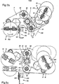
- FIGS. 10 and 11 A correspondingly modified exemplary embodiment is explained with reference to FIGS. 10 and 11.
- the sword corresponding to the sword 155 is missing and the collet 270 is only in one piece and has two clamping brackets 271, 272 with circularly curved clamping jaws 27 3 , the curvature of which is adapted to a tube piece 274 serving as a winding core.
- a centrally arranged winding core holder 280 is provided, which instead of the push rod 154 has a rod 282, on the free end of which a round clamping block 281 is attached.
- the tensioning block 281 moves into the interior of the tube piece 274 when the winding core holder 280 is extended.
- the rod 282 like the push rod 154, is mounted on the push rod 154 corresponding to the coupling element 121 on the coupling element 233 corresponding to the coupling element 121.
- a clamping mandrel 276 is fastened coaxially to the winder axis 275, which also paws into the tubular piece 274.
- the tensioning block 281 strikes the mandrel 276 and, like the Ouersteg 173, thereby takes the tensioning head back into the rotationally secured position.
- the sword 155 and the swords corresponding to this of the other winding holders can be omitted if the shoe is a sufficiently rigid winding core.
- Parts of the clamping head of a corresponding exemplary embodiment are shown in FIGS. 12 and 13.
- the sword is missing.
- a circular bushing 240 is provided on both sides, through which a mandrel 242, which is parallel to the winder axis 14 and is longitudinally displaceable, projects in the clamping head 241.
- the mandrel 242 is under the load of a compression spring 243 can be pressed back into the Ianere of the clamping head by overcoming the restoring force of this compression spring 243.
- dan arettchek the one who responds If there are holes in its end face, it is additionally held by the clamping mandrel 242 and the opposite, non-visible mandrel, which then engage in these blind holes when the clamping head is attached. If there are no blind holes, the mandrel 242 is not square and is pushed back by the board into the clamping head against the force of the spring 243.
- the collet 244 with its return spring 245 and its tolerance spring 246 is otherwise designed in exactly the same way as the collet 130 from FIG. 6 and also mounted in the clamping head 241 just like this.
- a driver 291 is mounted on the front end of the coupling piece 290 corresponding to the coupling element 121 and is fastened to the clamping head 241.
- the longitudinal displacement of the driver 291 with respect to the coupling element 290 is limited by a pickling corresponding to the bolt 1 63 with an associated longitudinal groove.
- deflection tubes 62, 63 can also be used in devices in which the brackets 6, 7 cannot be adjusted in their spacing.
- This deflection tube is fastened between the fixed brackets 301, 302 and is looped by the cloth web 303.
- the deflection tube 300 has an increasingly thicker diameter toward the center 304, which corresponds to the cloth web rides.
- the two tube halves thus formed are coated with a rib-shaped rib 305, 306.
- the apiral windings extend mirror-symmetrically to one another, with such an incline that the spiral paths are inclined upwards in the direction of the cloth web advance according to arrow 307 and act on the cloth web stretching outwards.
Abstract
Eine Wickelvorrichtung dient zum Aufwickeln von einfachen oder mehrfach zusammengefalteten Tuchbahnen mit zwei alternativ betriebenen Wicklern 13, 15, denen jeweils ein Umlenkrohr 62, 63 unmittelbar vorgeordnet ist. Jeder Wickler 13, 15 weist zwei koaxial angeordnete Wickelhalter 8 bis 11 auf, die beim Wickeln mit Spannzangen den zugekehrten Tuchbahnrand und das zugekehrte Wickelkernende einklemmen.A winding device is used to wind up single or multiple folded fabric sheets with two alternatively operated winders 13, 15, each of which has a deflection tube 62, 63 directly upstream. Each winder 13, 15 has two coaxially arranged winding holders 8 to 11, which clamp the facing edge of the cloth web and the facing end of the winding core when winding with collets.
Description
Die Erfindung betrifft eine wickelvorrichtung für Warenbahnen mit zwei Wicklern, die mit je beidseitig der Warenbahn ansetzbaren Wickelhaltern ausgestattet und mitsamt je einem vorgeordneten Umlenkelement achsparallel an einer drehbaren KonsolE gelagert sind und durch Schwenken der Konsole um 180° ihre Stellung austauschen können und abwechselnd in einer Wickelstellung einen angefangenen Wickel fertig wickelnd und in einer Wartestellung einen neuen Wickel beginnend betrieben werden und mit einer von der Konsole unabhängig gelagerten Trenn- vorrichtung, die auf einen Warenbahnabschnitt zwischen den be: den Wicklern einwirkt, und bei der die Warenbahn das Umlenkelement bei jedem Füllungsgrad des entstehenden Wickels teilweise umschlingend und anschließend an diese Umschlingung nur noch mit dem entstehenden wickel in Berührung geführt ist,The invention relates to a winding device for webs with two winders, which are equipped with winding holders that can be attached to both sides of the web and are mounted together with an upstream deflecting element in an axially parallel manner on a rotatable console and can exchange their position by pivoting the console through 180 ° and alternately in a winding position a commenced winding are operated starting done by wrapping and in a waiting position a new roll, and with an independently supported by the console T racing device on a web section between the be: acting the winders, and in which the web of the deflecting element in each degree of filling partially wrapping the resulting winding and then only being brought into contact with the resulting winding after this wrapping,
Aus der DE-AS 2 317 325 ist eine solche Wickelvorrichtung für Kunststoff-Folien bekannt, bei der ein Rohr als Wickelkern zwischen den beiden Wickelhaltern eines Wicklers verspannt wird, auf das dann die Kunststoff-Folie aufgewickelt wird. Beim Anwickeln lastet eine Anpreßwalze auf dem Anschnitt der Folienbahn und preßt diese gegen den Wickelkern, bis dieser Anschnitt fest am Wickelkern sitzt. Durch eine solche Anpreßwalze werden bei Warenbahnen, die zur Faltenbildung neigen, wie es inbesondere bei doublierten und mehrschichtig liegenden Tuchbahnen der Fall ist, Falten im Wickel hervorgerufen, die unerwünscht sind.Such a winding device for plastic films is known from DE-AS 2 317 325, in which a tube as a winding core is clamped between the two winding holders of a winder, on which the plastic film is then wound. When winding, a pressure roller rests on the cut of the film web and presses it against the winding core until this cut sits firmly on the winding core. Such a pressure roller causes wrinkles in the winding in the case of webs which tend to form folds, as is the case in particular in the case of doubled and multilayered cloth webs, which are undesirable.
Aufgabe der Erfindung ist es, eine Vorrichtung der eingangs genannten Art so auszugestalten, daß auch bei zu Faltenbil- dung neigenden warenbahnen solche Falten möglichst vermieden werden, insbesondere auch dann, wenn flache Wickel auf brettchenförmige Wickelkerne aufgewickelt werden. Dabei sollen Zwangspausen am Beginn eines neuen Wickels möglichst verkürzt werden.The object of the invention is to design a device of the type mentioned above so that even with manure to F altenbil- sloping webs such wrinkles are avoided if possible, especially if flat coils are wound on winding cores brettchenförmige. In doing so, forced breaks at the start of a new winding should be shortened as much as possible.
Die Erfindung ist dadurch gekennzeichnet, daß die Warenbahn gespannt zwischen den Wickelhaltern des in Wartestellung befindlichen Wicklers hindurch an den in Wickelstellung befindlichen Wickler geführt wird,
daß die Wickelhalter mit Klemmelementen ausgestattet sind, daß die Wickelhalter durch Axialverschieben aus einer abgesetzten Stellung neben der Warenbahn, die sie in Wartestel- lung des zugehörigen Wicklers einnehmen, in eine angesetzte Stellung verstellbar sind, in der die Klemmelemente den Rand der Warenbahn mitsamt einem eingeführten Wickelkern umgreifen und einklemmen und die sie beim Wickeln einnehmen, und
daß für jeden Wickelhalter eine Verdrehungssicherung vorgesehen ist, mit der die zugehörigen Klemmelemente in Wartestellung in einer Drehstellung arretiert sind, in der sie auf die Ebene der vorbeigeführten Warenbahn ausgerichtet sind.The invention is characterized in that the web of material is guided tensioned between the winding holders of the winder in the waiting position and to the winder in the winding position.
that the winding supports are equipped with clamping elements, in that the winding support by axial displacement from a remote position adjacent the web, they in W artestel- lung occupy the associated winder, are adjustable in an attached position in which the clamping elements together with the edge of the web of a grasp the inserted winding core and clamp it and take it in during winding, and
that an anti-rotation device is provided for each reel holder, with which the associated clamping elements are locked in the waiting position in a rotational position in which they are aligned with the plane of the web being passed.
Bei Beginn eines Wickelvorgangs wird die Warenbahn in der gespreizten Spannung, in der sie bereitgehalten wird, nur an ihren Rändern eingeklemmt, wobei gleichzeitig die Enden des Wickelkerns mit eingeklemmt werden. Die Spannung bleibt dadurch erhalten, und zwar auch in den einzelnen Lagen einer doublierten oder mehrfach geschichteten Tuchbahn, so daß, wie die Erfahrung gezeigt hat, unerwünschte Faltenbildung vermieden werden kann.At the start of a winding process, the material web is clamped only at its edges in the spread tension in which it is kept ready, the ends of the winding core being clamped at the same time. This maintains the tension, even in the individual layers of a doubled or multi-layered sheet, so that, as experience has shown, undesirable wrinkling can be avoided.
Die Erfindung wird nun anhand der beigefügten Zeichnung näher erläutert.The invention will now be explained in more detail with reference to the accompanying drawing.
- In der Zeichnung zeigt:
Figur 1 eine Wickelvorrichtung, gesehen von vorn,Figur 2 die Ansicht gemäß demPfeil 2 ausFigur 1,Figur 3 den Schnitt gemäß demPfeil 3 aus Figur 1,- Figur 4 a bis c schematisch im Querschnitt je eine Tuchbahn,
- Figur 5 a bis c einige am Wickelvorgang beteiligte Teile der Vorrichtung in der Ansicht entsprechend
Figur 3, und zwar- unter 5 a in einer ersten Funktionsstellung,
- unter 5 b in einer zweiten Funktionsstellung und
- unter 5 c in einer dritten Funktionsstellung,
- Figur 6 a bis c einen Wickelhalter im Schnitt gemäß
Pfeil 6 ausFigur 2, und zwar- unter 6 a mit abgesetztem Spannkopf,
- unter 6 b mit vorgeschobenem Spannkopf und
- unter 6 c mit angesetztem Spannkopf,
Figur 7 den vorderen Teil des einen Wickelhalters im Teilschnitt gemäß demPfeil 7 aus Figur 6 c,Figur 8 die Ansicht gemäß demPfeil 8 ausFigur 7, jedoch nur die rechte Hälfte, weil die linke Hälfte dazu spiegelsymmetrisch ist,Figur 9 im Schnitt gemäßPfeil 9 ausFigur 8 das vordere Ende des Wickelhalters,Figur 10 eine Abänderung des Wickelhalters in der Darstellungentsprechend Figur 8,Figur 11 im Schnitt gemäßPfeil 11 den.vorderen Teil des Wickelhalters ausFigur 10,Figur 12 eine weitere Abänderung des Wickelhalters in der Darstellungentsprechend Figur 8,Figur 13 im Schnitt gemäßPfeil 13 ausFigur 12 das vordere Ende des Wickelhalters,Figur 14 die eine Umlenkrolle vergrößert ausFigur 2 herausgezeichnet und aufgebrochen, undFigur 15 eine abgeänderte Ausgestaltung der Umlenkrolle in Ansicht.
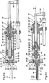
- 1 shows a winding device, seen from the front,
- FIG. 2 shows the view according to
arrow 2 from FIG. 1, - FIG. 3 shows the section according to
arrow 3 from FIG. 1 , - FIG. 4 a to c schematically in cross-section a sheet of cloth,
- Figure 5 a to c some parts of the device involved in the winding process in the view corresponding to Figure 3, namely
- under 5 a in a first functional position,
- under 5 b in a second function position and
- under 5 c in a third functional position,
- Figure 6 a to c a winding holder in section according to
arrow 6 of Figure 2, namely- under 6 a with offset clamping head,
- under 6 b with advanced clamping head and
- under 6 c with attached clamping head,
- FIG. 7 shows the front part of a winding holder in partial section according to
arrow 7 from FIG. 6 c, - FIG. 8 shows the view according to
arrow 8 from FIG. 7, but only the right half, because the left half is mirror-symmetrical to it, - FIG. 9 in section according to
arrow 9 from FIG. 8 the front end of the winding holder, - 10 shows a modification of the winding holder in the illustration corresponding to FIG. 8,
- FIG. 11 in section according to
arrow 11 the front part of the winding holder from FIG. 10, - FIG. 12 shows a further modification of the winding holder in the illustration corresponding to FIG. 8,
- FIG. 13 in section according to
arrow 13 from FIG. 12 the front end of the winding holder, - 14 shows a deflection roller enlarged from FIG. 2 and broken open, and
- Figure 15 shows a modified configuration of the deflection roller in view.
In der Zeichnung ist mit 1 das Maschinengestell bezeichnet, an dem in zwei Drehlagern 2 und 3 eine um die Konsolenachse 4 drehbar gelagerte Konsolenwelle 5 gelagert ist. An der Konsolenwelle 5 sind längsverschieblich aber drehsteif zwei Konsolen 6, 7 gelagert. Die Konsolen können auf der Konsolenwelle 5 verschoben werden durch Drehen eines Handrades, das an der zugehörigen Konsole gelagert ist und ein Ritzel treibt, das in eine Zahnstange eingreift, die an der Konsolenwelle 5 befestigt ist. Der Übersicht halber ist nur in Figur 5 das Handrad 38 für die Konsole 7 eingezeichnet. Die Zahnstange ist mit 39 bezeichnet. Die Zahnstange dient gleichzeitig als Verdrehungssicherung für die Konsole auf der Konsolenwelle 5. Durch Verschieben der Konsolen wird die Vorrichtung an verschiedene Breiten der Tuchbahn 16 angepaßt.In the drawing, 1 denotes the machine frame, on which a
An den Konsolen sind vier Wickelhalter 8, 9, 10, 11 gelagert, von denen die Wickelhalter 8, 10 koaxial zur Wicklerachse 12 angeordnet sind und den Wickler 13 bilden, während die wickelhalter 9, 11 koaxial zur Wicklerachse 14 angeordnet sind und den Wickler 15 bilden. Die Wickelhalter 8, 9, 10, 11 sind in einander zugekehrten Seiten der Konsolen 6, 7 paarweise aufeinander zu gerichtet angeordnet. Zwischen den Wickelhaltern erstreckt sich die in den Figuren 5 a bis 5 c eingezeichnete Tuchbahn 16. Die Tuchbahn 16 kann einfach sein, wie in Figur 4 a dargestellt; zweifach, also doubliert, wie in Figur 4 b dargestellt; doppelt doubliert, also vierfach, wie in Figur 4 d dargestellt; dreifach gelegt, wie in Figur 4 c dargestellt oder anders mehrfach gelegt sein. Die Längsfaltung entlang der Längsfalten 18 bis 23 dient dazu, eine breitere Tuchbahn gemäß Figur 4 b, c und d auf einen gemäß Doppelpfeil 24 weniger breiten Wickel 25 aufzuwickeln, um die Lagerhaltung zu erleichtern.Are on the brackets four
Die Tuchbahn 16 gelangt von der vorgeordneten Maschine 17 - abgesehen von den Längsfalten - faltenfrei gespannt in die Wickelvorrichtung und soll von der Wickelvorrichtung zu Wickeln entsprechend dem Wickel 25 aufgewickelt werden und dabei soll die Bildung zusätzlicher neuer Falten, Aufwerfungen und dergleichen vermieden werden.The web of
Zum Antrieb der Wickler 13 und 15 dienen den einzelnen Wickelhaltern jeweils zugeordnete Antriebsmotoren 40, 41, 42, 43, die, wie aus Figur 2 und 3 ersichtlich, neben den zugehörigen Wickelhaltern auf der betreffenden Konsole 6 beziehungsweise 7 gelagert sind. Jeder Wickelhalter wird also direkt angetrieben durch den ihm zugeordneten Antriebsmotor. Durch diese Antriebsmotoren werden Spannköpfe 44, 45, 46, 47 der einzelnen Wickelhalter um die jeweilige Wicklerachse 12, 14 rotierend beim Wickeln angetrieben. Die Spannköpfe 44, 45, 46, 47 sind drehbar und längsverschieblich im zugehörigen Wickelhalter gelagert. Zur Längsverschiebung dienen den einzelnen Wickelhaltern jeweils zugeordnete hydraulische Hubzylinder 50, 51, 52, 53, die jeweils neben dem zugehörigen Wickelhalter achsparallel zu diesem an der betreffenden Konsole 6 beziehungsweise 7 gelagert sind und über je einen Scubbügel, zum Beispiel dem Schubbügel 56, auf eine Schubstange 57 des betreffenden Wickelhalters 10 einwirken.Drive
Die Wickelhalter 8, 9, 10, 11 sind unter sich gleich ausgebildet und spiegelsymmetrisch zur Symmetrieebene 58, die senkrecht auf der Zeichenebene der Figur 1-steht, angeordnet. Die Wickelhalter eines Wicklers, also zum Beispiel die Wickelhalter 9, 11 des Wicklers 15, werden gemeinsam und synchron betrieben. Es ist nicht unbedingt erforderlich aber zweckmäßig, zur Synchronisation der Drehbewegung eine Einrichtung vorzusehen. Diesem Zweck dient für die Wickelhalter 9, 11 eine drehbar an beiden Konsolen achsparallel zur Wicklerachse 14 gelagerte Kupplungswelle 60, die drehsteif mit den beiden Wickelhaltern 9, 11 verbunden ist. Die entsprechende Kupplungswelle für die Wickelhalter 8, 10 ist mit 61 bezeichnet.The winding
Das Antriebszahnrad 35 des Antriebsmotors 41 kämmt mit einem Antriebszahnrad 36 des Wickelhalters 10. Das Antriebszahnrad 35 kämmt außerdem mit einem Umlenkzahnrad 37, das drehsteif aber axial verschieblich auf der Kupplungswelle 61 steckt. Der gegenüberliegende Wickelhalter 8 des gleichen Wicklers 15 ist an die Drehbewegung der Kupplungswelle 61, und damit auch an die des Wickelhalters 10, synchronisiert durch das Umlenkzahnrad 114, das drehsteif und axial verschieblich auf der Kupplungswelle 61 steckt und mit dem Antriebszahnrad 115 des Antriebsmotors 43 kämmt.The
Die Kupplungswellen 60, 61 erstrecken sich über den maximalen Abstand der beiden Konsolen 6, 7 und sind in diesen axial verschieblich gelagert, um die Längsverschiebung'der Konsolen entlang der Konsolenwelle 5 nicht zu behindern.The Kupplun g swellen 60, 61 extend beyond the maximum distance of the two
Koaxial zu den Kupplungswellen 60, 61 sind Umlenkrohre 62, 63 angeordnet. jedes dieser Umlenkrohre, zum Beispiel das Umlenkrohr 63, vergleiche Figur 14, besteht aus zwei Rohrabschnitten 64, 65, die paarweise teleskopartig übereinandergesteckt sind und von denen ein Rohrabschnitt 64 an der einen Konsole 7 und der andere Rohrabschnitt 65 an der anderen Konsole 6 befestigt _ist. Das durch die Rohrabschnitte gebildete Umlenkrohr 63 ist dadurch teleskopartig auseinanderziehbar und zusammensteckbar und folgt damit in seiner Länge dem Abstand zwischen den Konsolen 6,7. Das Umlenkrohr 63 ist auf seinem Umfang mit vorspringenden Rippen 67 besetzt, die sich von der Symmetrieebene 58 und damit von der Mitte der Tuchbahn 16 ausgehend in Förderrichtung gemäß Pfeil 70 schräg zur Seite erstrecken. Die Rippen erstrecken sich jeweils nur über diejenigen äußeren Teile der Rohrabschnitte 64, 65, die beim teleskopartigen Zusammenschieben nicht übereinandergeraten. Die Rippen 67 sind, bezogen auf die Achsrichtung der zugehörigen Umlenkachse 71, gemäß Doppelpfeil 73 schmaler als 1/10 der Breite gemäß Doppelpfeil 74 der Zwischenräume 75, 76 zu den benachbarten Rippen. Die Rippen 67 werden gebildet durch zwei Spiralen 77, 78.Coaxially to the
Statt ein Umlenkrohr zu verwenden, genügt auch eine Umlenkschiene, die eine in Umschlingungsrichtung der Tuchbahn gekrümmte Umschlingungsfläche aufweist, die sich über den größten auftretenden Umschlingungswinkel erstreckt. Die Rippen sind vorteilhaft vorgesehen, können aber auch entfallen.Instead of using a deflection tube, it is also sufficient to use a deflection rail that has a wrapping surface that is curved in the wrapping direction of the fabric web and that extends over the greatest wrapping angle that occurs. The ribs are advantageously provided, but can also be omitted.
Das Umlenkrohr 63 ist nicht drehbar. In Abänderung kann jedoch das Umlenkrohr 63 drehbar um die Umlenkachse 71 gelagert sein, es kann um diese Achse rotierend antreibbar sein und zu diesem Zweck an den Antrieb des zugehörigen Wicklers gekoppelt sein.The
Das Umlenkrohr 63 gehört zu dem Wickler 13. Das Umlenkrohr 62, das entsprechend ausgebildet ist wie das Umlenkrohr 63 gehört zu dem Wickler 15.The
Wichtig ist, daß je ein Umlenkrohr 62, 63 oder je ein Umlenkelement, wie aus Figur 3 und 5 a ersichtlich, jedem der Wickler zugeordnet ist und unmittelbar aufwärts dieses zugeordneten Wicklers angeordnet ist. Das Umlenkelement ist so angeordnet, daß bei maximal gefülltem Wickel zwischen Umlenkelement und Wickel mindestens noch ein Toleranzabstand 174 (vergleiche Figur 5 a) besteht, damit sich der gefüllte Wickel einwandfrei am Umlenkelement vorbeidrehen kann. Wichtig ist außerdem, daß das Umlenkelement so weit versetzt angeordnet ist, daß bei gefülltem Wickel die strammgezogene Tuchbahn das Umlenkelement mit einem Umschlingungswinkel 79 von mindestens 10° umschlingt, damit die Tuchbahn 16 auch bei maximal ge-fülltem Wickel nicht unerwünscht von dem Umienkelement abhebt und flattert. Bei weniger gefülltem Wickel ergibt sich, wie aus Figur 5 a ersichtlich, dann ein größerer Umschlingungswinkel 79.It is important that a deflecting
Wichtig ist, daß anschließend an die Umschlingung des Umlenkelementes die Tuchbahn 16 nur mit dem entstehenden Wickel in Berührung ist. Die Tuchbahn gelangt im Anschluß an das Umlenkelement unmittelbar auf den Wickel. Sie wird dort frei aufgewickelt und steht nicht unter der Druckbelastung einer Andruckwalze, die von außen auf dem sich bildenden Wickel lastet. Eine solche Andruckwalze würde zu unerwünschter Faltenbildung führen.It is important that after the looping of the deflecting element, the
Oberhalb der Tuchbahn 16, den Wicklern 13, 15 vorgeordnet, ist ein Brettchenmacazin 80 angeordnet, das an dem Maschinengestell 1 befestigt ist. Das Brettchenmagazin ist mit einem Stoß von als Wickelkerne dienenden Brettchen 81 gefüllt, von denen das jeweils unterste Brettchen 82 mit Hilfe eines dem Brettchenmagazin 80 zugeordneten Zuteilers 83 in Pfeilrichtung 84 abgegeben wird, worauf die anderen Brettchen in Pfeilrichtung 85 nach unten nachrücken. Das Brettchenmagazin ist auf verschieden lange Brettchen entsprechend der Breite der jeweils verarbeiteten Tuchbahn 16 anpaßbar.Above the
Der Zuteiler 83 legt das abgegebene Brettchen auf die dann stillstehende Tuchbahn 16 zwischen den beiden Wickelhaltern 9, 11 des in Wartestellung befindlichen Wicklers 15.The allocator 83 places the dispensed board on the then
Das Brettchernmagazin 80 ist an verschiedene Breiten der Tuchbahn anpaßbar. Dazu sind die beiden Magazinwangen 86, 87 an querverschiebbaren Wangenträgern 31, 32 befestigt. Der Wangenträger 31 ist an einer Gleitstange 91 und an einer dazu parallelen Gewindespindel 90 in Richtung der Konsolenachse 4 verschiebbar gelagert. Zum Verschieben wird die Gewindespindel 90 mit der Handkurbel 26 gedreht. Gewindespindel 90 und Gleitstange 91 sind in Lagerschilden 28, 92 am Maschinengestell 1 gelagert. Der Wangenträger 32 ist entsprechend gelagert. Die zugehörige Handkurbel ist mit 27, die Stange mit 89 und die Gewindespindel mit 88 bezeichnet.The
Unterhalb der Wickler 13, 15 ist an.einem Querträger 184 eine allgemein mit 180 bezeichnete Trennvorrichtung angeordnet. Der Querträger 184 ist beidseitig an je einem hydraulischen Hubzylinder 185, 186 höhenverstellbar am Maschinengestell 1 gelagert. An dem Querträger 184 sind auf die Tuchbahnbreite verteilt rotierend antreibbare Messerscheiben 187 angeordnet, deren Umfang jeweils ein Vieleck ist und als Schneide ausgebildet ist. Die Messerscheiben 187 bilden mit ihren Schneiden eine sich über die ganze Tuchbahnoreite erstreckende, horizontale, kombinierte Schneide, wie durch die strichpunktierte Linie 188 in Figur 1 angedeutet. In der in Figur 1 und 5 gezeichneten unteren Ruhestellung ist die Trennvorrichtung 180 unwirksam. Zum Durchführen eines Trennschnittes wird sie nach oben gefahren, bis sie mit ihrer kombinierten Schneide 188 die Tuchbahn durchsetzt und auf ihrer ganzen Breite durchschneidet. Die Trennvorrichtung 180 ist so angeordnet, daß sie, wie besonders gut aus Figur 5 a ersichtlich, unmittelbar abwärts des in Wartestellung befindlichen Wicklers 15 wirksam ist.Below the
Die Ausgestaltung der Wichelhalter wird nun anhand des Wickelhalters 10 beschrieben.The configuration of the wich holder will now be described with reference to the
Im wicklergehäuse 101 ist eine Mitnehmerhülse 113 in Kugellagern 103, 104 und ein Drehschiebelager 112 im Kugellager 102 drehbar aber nicht längsverschieblich gelagert. In dem Drehschiebelager 112 und in der Mitnehmerhülse 113 ist das Lagerrohr 107 längsverschieblich gelagert. Mit 152 ist ein Führungskeil bezeichnet, der das Lagerrohr 107 zwingt, den Drehbewegungen der Mitnehmerhülse 113 zu folgen. Auf der Mitnehmerhülse 113 ist das Antriebszahnrad 36 befestigt. In dem Lagerrohr 107 steckt ein Kupplungselement 121, das im Lagerrohr längsverschieblich gleitend ist. Am vorderen Ende des Kupplungselementes ist die Schubstange 154 eines Schwertes 155 gelagert. Die Schubstange 154 ist flach und in einer formschlüssig passenden Längsnut längsverschieblich im Kupplungselement 121, und zwar nach hinten abgestützt auf einer Druckfeder 164. Die Längsverschiebung ist begrenzt durch ein Langloch 162 in der Schubstange 154, durch das ein Bolzen 163 des Kupplungselementes gesteckt ist. Die Schubstange 154 ist verdrehungssicher in einem Schlitz 165 der Stirnfläche 140 geführt. Im rückwärtigen Ende des Kupplungselementes 121 ist drehbar in Kugellagern 190, 191 gegen Längsverschiebung gesichert das vordere verjüngte Ende der Schubstange 57 angekuppelt. Mit 192 ist ein Lrucklager bezeichnet.In
Am freien Ende des Lagerrohrs 107 ist der Spannkopf 46 befestigt. Der Spannkopf ist in Figur 6 a in seiner zurückgezogenen Stellung gezeichnet, in der ein als Verdrehungssicherung dienender, am Spannkopf befestigter Keilnocken 103 in eine entsprechend diametral gegenüberliegende Aufnahme 111 des Wicklergehäuses 101 eingefallen ist. Dadurch ist der Spannkopf gegenüber dem Wicklergehäuse in seiner zurückgezogenen Stellung in einer durch die Aufnahme 111 definierten Winkelstellung unverdrehbar fixiert.The clamping
Die Drehbewegung des Spannkopfes um die Wicklerachse 14 wird eingekoppelt über eine nicht dargestellte Rutschkupplung und über das Zahnrad 36. Die Rutschkupplung dient als Ausgleich, wenn bei auslaufender Drehbewegung die Verdrehungssicherung des Keilnockens 108 einractet. Der Antriebsmotor wird von einem nicht dargestellten Tastschalter abgeschaltet, wenn der Keilnocken 108 eingerastet ist.The rotary movement of the clamping head about the
Im Spannkopf ist eine Spannzange 130 gelagert mit vier Spannbacken, von denen jedoch in Figur 6 nur zwei Spannbacken 138, 139 sichtbar sind. Die anderen, nicht sichtbaren Spannbacken sind spiegelsymmetrisch zur Spiegelsymmetrieebene 168 aus Figur 8 zu den sichtbaren Spannbacken 138, 139 angeordnet und ausgebildet. Alle Spannbacken fassen in einer gemeinsamen Ebene. Wenn die Verdrehungssicherung durch die Keilnocken 108 eingefallen ist, steht die Spannzange so, daß sie in der Ebene der Tuchbahn 16 fasst, wie das für den in Figur 5 a in Bereitstellung stehenden Wickler 15 der Fall ist.A
Die beiden Spannbügel 131, 132 der Spannzange 130 sind um die Spannzangenachsen 133 und 129 auf- und zuschwenkbar. In Figur 6 a und 6 b ist die Spannzange geöffnet. Die beiden Spannbügel sind in geöffnetem Zustand unter der Druckwirkung von Druckfedern 134, 135 mit den Rollen 158, 159 gegen das Schwert 155 geschwenkt. Die Spannbacken 138, 139 ragen aus der der Tuchbahn 16 zugekehrten Stirnfläche 140 heraus und können bei angesetzter, also geschlossener Spannzange ein als Wickelkern dienendes Brettchen, zum Beispiel das Brettchen 82, zusammen mit dem Rand der Tuchbahn 16 und dem Schwert 155 fassen. Zum Ausgleich von Toleranzen hinsichtlich der Brettchenstärke und der Tuchbahnstärke bestehen die Spannbügel 131, 132 aus zwei gegeneinander beweglichen Teilen, die durch dazwischengesetzte, als Tellerfedern ausgebildete Druckfedern 160, 161 gegenüber verfedert sind.The two clamping
Das als Wickelkernhalter dienende Schwert 155 besteht außer aus der Schubstange aus den beiden Bügeln 176, 177 und dem Quersteg 173 und ist flach ausgebildet. Es erstreckt sich in ausgefahrenem Zustand nicht ganz bis zur Tuchbahnmitte 179. Die beiden Bügel-176, 177 sind in Schlitzen der Stirnflä- che 140 geführt.The ickelkernhalter as W serving sword 155 consists not only from the push rod of the two
In der in Figur 6 a gezeichneten abgesetzten Stellung ist das Kupplungselement 121 mit dem Schwert 155 ganz zurückgezogen. Der Quersteg 178 stößt dabei an die Stirnfläche 140 an und hat den Spannkopf 46 und das Lagerrohr 107 mit zurückgezogen. Alle Teile des Wickelhalters 10 befinden sich nun, wie in Figur 6 a gezeichnet, außerhalb der Tuchbahn 16. Die Spannzangen stehen ausgerichtet auf die Tuchbahnebene.In the remote position shown in FIG. 6 a, the
Aus der Stellung gemäß Figur 6 a fährt zum Ansetzen das Kupplungselement nach vorne und mit ihm das Schwert 155. An einem Abschnitt der Vorwärtsbewegung des Schwertes schlagen Anschläge 153, 166, die am rückwärtigen Ende der Bügel 176, 177 befestigt sind, an der Rückseite des Spannkopfes 46 an - vergleiche Figur 7 -, so daß der Spannkopf der weiteren Ausfahrbewegung des Schwertes 155 folgen muß, bis er schließlich in die in Figur 6 b gezeichnete Stellung gelangt, in der die weitere Vorschubbewegung des Lagerrchrs 107 begrenzt ist, weil ein Anschlag 120 des Lacarrohrs gegen die rückwärtige Kante der Mitnehmerhülse 113 schlägt. In dieser Stellung erstreckt sich das Schwert 155 parallel zur Tuchbahn über das inzwischen eingelegte Brettchen 32 nicht ganz bis zur Tuchbahnmitte 179 und die Spannbacken 138, 139 ... sind noch geöffnet und umgreifen in geöffnetem Zustand den Rand der Tuchbahn 16, den Rand des Brettchens 82 und die beiden Bügel 176, 177 des Schwertes 155. Einer weiteren Vorwärtsbewegung der Schubstange 57 kann das Lagerrohr 107 und das Schwert 155 nicht mehr folgen. Das Kupplungselement 121 folgt aber der Vorschubbewegung und dadurch schiebt sich das stillstehende Schwert gegen die Kraftwirkung der Druckfeder 164 in das Kupplungselement 121 hinein, bis der Bolzen 163 diese Einschubbewegung begrenzt. Diese Endstellung ist in Figur 6 c gezeichnet.From the position shown in FIG. 6 a, the coupling element moves forward and with it the
Beim Vorschub des Spannkopfes 46 aus der Stellung gemäß Figur 6 a löst sich die Verdrehungssicherung des Keilnockens 108 mit der Aufnahme 111. Der Spankopf 46 behält aber die durch die Verdrehungssicherung eingestellte Winkelstellung, bis er in die angesetzte Stellung gemäß Figur 6 c geraten ist und den Rand der Tuchbahn 16, das Erettchen 32 und das Schwert 155 eingeklemmt hat.During the advance of the S
Kurz vor Erreichen der Endstellung treffen Schrägflächen 156, 157 am vorderen Ende des Kupplungselementes 121 auf die Rollen 158, 159, die am rückwärtigen Ende der Spannbügel 131, 132 angebracht sind, wodurch die Spannzange 130 gegen die Kraftwirkung der Druckfedern 134, 135 geschlossen wird. Die Rollen 158, 159 geraten dabei auf die Seitenflächen des Kupplungselementes 121, wodurch die Spannzange in ihrer Schließstellung verriegelt ist und das eine Ende des Brettchens mit dem zuge- hörigen Tuchbahnrand 72, wie aus Figur 6 c ersichtlich, festhält und mit dem Schwert 155 verklammert. Die Spannbacken 138, 139 klemmen dabei den Bügel 176 und die anderen spiegelsymmetrisch dazu am gleichen Spannkopf angeordneten Spannbacken den Bügel 177 des Schwertes 155 ein.Shortly before reaching the end position,
Die Drehbewegung über das Antriebszahnrad 36 wird erst eingekuppelt, wenn der Wickelhalter sich in seiner angesetzten, in Figur 6 c gezeichneten Stellung befindet. Dann dreht sich mit der Mitnehmerhülse 113 das Lagerrohr 107 und mit dem Lagerrohr der Spannkopf, die Spannzange und das Schwert. Das Kupplungselement dreht sich mit, während die Schubstange 57 an der Drehbewegung nicht reilnimmt, ebensowenig das Wicklergehäuse 101.The rotary movement via the
Die Wirkungsweise der Vorrichtung ist folgende.The operation of the device is as follows.
Eine von der Maschine 17 unter Spannung und fertig längsgefaltete Tuchbahn 16 gelangt zunächst in die Spannvorrichtung 170 mit zwei Umlenkwalzen 171, 172 und einer dazwischen in einer Schlaufe wirksamen Tänzerwalze 173, die durch Gewichts- oder Federbelastung Ungleichmäßigkeiten im Bandtransport ausgleicht und eine gleichmäßige Zugspannung der Tuchbahn bewirkt. Die Konsolen stehen in der Winkelstellung wie in Figur 5 für die Konsole 7 gezeichnet, in der sich der Wickler 13 in Wickelstellung und der Wickler 15 in Wartestellung befinder dissen beiden Wicklern sind in Figur 5 a bis 5 c jeweils nur die Wickelhalter 10 und 11 sichtbar. Die gegenüberliegenden Wickelhalter werden synchron betrieben und stehen koaxial.One of the
Die Tuchbahn 16 läuft von der Umlenkwalze 172 zwischen den Wickelhaltern des Wicklers 13 hindurch an das Umlenkrohr 63. Die Tuchbahn umschlingt dabei das Umlenkrohr 63 auf dem Umschlingungswinkel 79 und wird dabei durch die Rippen nach außen gereckt. Von diesem Umlenkrohr gelangt die Tuchbahn 16 an den Umfang des Wickels, der durch die Drehbewegung der Spannköpfe des Wicklers 13 in Pfeilrichtung 175 umgedreht und dabei aufgewickelt wird. Sobald der Wickel 25 die gewünschte Füllung erreicht hat, wird das durch einen Fühler festgestellt, der daraufhin den Antrieb des Wicklers 13 stillsetzt. Der Fühler ist nicht dargestellt und auch nicht die Steuerleitungen für die durch den Fühler ausgelösten Steuerfunktionen. Das gilt auch für alle anderen Fühler und Steuerfunktionen. Gleichzeitig mit dem Stillsetzen des Wicklers 13 wird der Stoffbahnvorschub an der Maschine 17 abgeschaltet und der Vorschub eines Brettchens 82 im Brettchenmagazin 80 ausgelöst. Das Brettchen 82 gelangt dadurch auf die Tuchbahn 16 zwischen die Spannköpfe des Wicklers 15. Die Spannköpfe des Wicklers 15 stehen, bedingt durch die verdrehungssicherung, die durch den dem Keilnocken 108 entsprechenden Keilnocken gebildet wird, in einer Winkellage, in der sie das flach auf der Tuchbahn 16 liegende Brettchen 82 mit der Tuchbahn 16 erfassen können. Sobald.das Brettchen eingeschoben ist, werden die Spannköpfe des Wicklers 15 aus ihrer abgesetzten Stellung gemäß Figur 6 a, die sie in Wartestellung innehatten, in ihre angesetzte Stellung gemäß Figur 6 c verstellt, in der das Brettchen durch die von beiden Seiten eingeschobenen Schwerter, die dem Schwert 155 aus Figur 6 und 7 entsprechen, unterstützt ist und an beiden Seiten mitsamt den Schwertern und den Tuchrändern eingeklemmt ist. Die Schwerter erstrecken sich dabei unter der Tuchbahn und versteifen beim wickeln das Brettchen. Die Schwerter können das Brettchen beim Wickeln auch ersetzen.The
Der Tuchbahnabschnitt zwischen den Wicklern 13 und 15 ist nun verspannt durch die nun angesetzten Spannzangen des Wicklers 15. Nun wird auf diesen verspannten Tuchbahnabschnitt die Trennvorrichtung 180 angesetzt, inden die Schneidmesser durch den Antriebsmotor 132 in Rotation versetzt werden und in Pfeilrichtung 183 nach oben verstellt werden, bis sie in die Tuchbahn eingreifen und diese auf ihrer ganzen Breite durchschneiden. Ist das geschehen, dann weicht die Trennvorrichtung 180 wieder in ihre Ausgangslage zurück und der Motor 182 kann abgeschaltet werden. Er kann aber auch leer weiterlaufen bis zum nächsten Trennschnitt.The T uchbahnabschnitt between the
Unmittelbar nach der Trennung beginnt der Wickler 15 mit seiner Rotationsbewegung in Pfeilrichtung 200 und gleichzeitig damit wird der Tuchbahnvorschub in der Maschine 17 eingeschaltet und der Wickler 15 beginnt, einen neuen Wickel auf das Brettchen 82 aufzuwickeln. Dabei beginnt die Konsolenwelle 5 eine Schwenkbewegung um 180° in Pfeilrichtung 181, vergleiche Figur 5, an deren Ende die beiden Wickler 13 und 15 ihre Positionen ausgetauscht haben. Die Wickler drehen sich um die Wicklerachsen im gleichen Drehsinn gemäß Pfeil 200 und Pfeil 175 wie sich die Konsolen 6, 7 um die Konsolenachse gemäß Pfeil 181 drehen. Der gleiche Drehsinn der Konsolen einerseits und der Wickler andererseits begünstigt das faltenfreie Aufwickeln während des Drehvorganges der Konsolen.Immediately after the separation, the winder 15 begins its rotational movement in the direction of the
Der Wickler 13 vollführt bei Beginn der Schwenkbewegung der Konsolenwelle 5 einige langsame Umdrehungen in Pfeilrichtung 175 und wickelt dabei das durch den Trennvorgang entstandene freie Tuchbahnenda 202 vollends auf. Ist das geschehen, dann gibt der Wickler 13 den gefüllten Wickel 25 frei und läßt ihn abfallen, indem die Spannköpfe mit den Schwertern in ihre abgesetzte Stellung entsprechend Figur 6 a zurückgezogen werden. Am Ende der 180°-schwenkbewgung der Konsolenwelle haben die beiden Wickler 13, 15 ihre Stellung gemäß Figur 5 gegeneinander ausgetauscht, der Wickler 15 wickelt den begonnenen Wickel fertig in der wickelstellung, die in Figur 5 der Wickler 13 innehat, und der Wickler 13 saeht in Wartestellung, die in Figur 5 der Wickler 15 innehat.At the start of the pivoting movement of the
Statt brettchenförmiger Wickelkerne kann man auch andere Wickelkerne verwenden, zum Beispiel rohrförmige. Für diesen Fall ist es aber nötig, entsprechend angepaßte Spannzangen vorzusehen. Ein entsprechend modifiziertes Ausführungsbeispiel wird anhand der Figuren 10 und 11 erläutert. Bei diesem Ausführungsbeispiel fehlt das dem Schwert 155 entsprechende Schwert und die Spannzange 270 ist nur einteilig und hat zwei Spannbügel 271, 272 mit kreisförmig gebogenen Spannbacken 273, die in ihrer Krümmung einem als Wickelkern dienenden Rohrstück 274 angepaßt sind. Anstelle des Schwertes ist ein zentral angeordneter wickelkernhalter 280 vorgesehen, der anstelle der Schubstange 154 einen Stab 282 aufweist, an dessen freiem Ende ein runder Spannklotz 281 befestigt ist. Der Spannklotz 281 fährt bei ausgefahrenem wickelkernhalter 280 in das Innere des Rohrstückes 274. Der Stab 282 ist entsprechend wie die Schubstange 154 an dem dem Kupplungselement 121 entsprechenden Schubstange 154 an dem dem Kupplungselement 121 entsprechenden Kupplungselement 233 gelagert. An der der Stirnfläche 140 entsprechenden Stirnfläche 27 des Spannkopfes ist koaxial zur Wicklerachse 275 ein Spanndorn 276 befestigt, der ebenfalls in das Rohrstäck 274 hineinpaft. Beim Zurückfahren des Wickelkernhalters 230 schlägt der Spannklotz 281 an dem Spanndorn 276 an und nimmt dadurch entsprechend wie der Ouersteg 173 den Spannkopf mit zurück in die verdrehungsgesicherte Stellung.Instead of board-shaped winding cores, other winding cores can also be used, for example tubular ones. In this case, however, it is necessary to provide appropriately adapted collets. A correspondingly modified exemplary embodiment is explained with reference to FIGS. 10 and 11. In this embodiment, the sword corresponding to the
Gemäß einer anderen Abänderung des dargestellten Ausführungsbeispiels kann das Schwert 155 und die diesem entsprechenden Schwerter der anderen Wickelhalter entfallen, wenn das Brefttchen ein hinreichend steifer Wickelkern ist. Teile des Spannkopfes eines entsprechenden Ausführungsbeispiels sind in Figur 12 und 13 dargestellt. Bei diesen Ausführungsbeispiel fehlt das Schwert. Statt dessen ist aber beidseitig anstelle der Durchführung für die Bagel 176, 177 eine kreisrunde Durchführung 240 vorgesehen, durch die je ein parallel zur Wicklerachse 14 längsverschieblich im Spanrkopf 241 gelagerter Spanndorn 242 ragt. Der Spanndorn 242 steht unter der Belastung einer Druckfeder 243 kann mit Ünarwindung der Rückstellkraft dieser Druckfeder 243 in das Ianere des Spannkopfes zuruckgedrückt werden. dan arettchek, des an antsprechenden Stellen seiner Stirnseite Löcher hat, wird durch den Spanndcrn 242 und dem gegenüberliegerden, nicht sichtbaren Spanndorn, die dann bei angesetztem Spannkopf in diese Sacklöcher eingreifen, zusätzlich gehaltert. Wenn keine Sacklöcher da sind, ist der Spanndorn 242 unwinkaam und wird von dem Brettchen in den Spannkopf gegen die Kraftwirkung der Feder 243 zurückgedrängt.According to another modification of the exemplary embodiment shown, the
Die Spannzange 244 mit ihrer Rückstellfeder 245 und ihrer Toleranzfeder 246 ist im übrigen genauso ausgebildet wie die Spannzange 130 aus Figur 6 und auch genauso wie diese im Spannkopf 241 gelagert.The
Damit der Spannkopf 242 auch bei fehlendem Schwert eine Axialbewegung durchführen kann ist am vorderen Ende des dem Kupplungselement 121 entsprechenden Kupplungsstückes 290 ein Mitnehmer 291 längsverschieblich gelagert, der am pannkopf 241 befestigt ist. Die Längsverschiebung des Mitnehmers 291 gegen- über dem Kupplungselement 290 ist durch einen dem Bolzen 163 entsprechenden Beizen mit zugehöriger Längsnut begrenzt.So that the clamping
Anstelle der Umlenkrohre 62, 63 können bei Vorrichtungen, bei denen die Konsolen 6, 7 nicht in ihrem Abstand verstellbar sind, auch andere Umlenkrohre verwendet werden, wie das in Figur 15 dargestellte umlenkrohr 30C. Dieses Umlenkrohr ist zwischen den feststehenden Konsolen 301, 302 befestigt und wird von der Tuchbahn 303 unschlungen. Das Umlenkrchr 300 hat zur Rchrmitte 304, die der Tuchbahnritte entspricht, zunehmend stärkeren Durchmesser, Dia beiden so entstehenden Rohrhälften sind mit einer spiraiförmi pen Rippe 305, 306 belegt. Die apiralwindungen erstrecken sich Spiegelsymmetrisch zueinander, und zwar mit einer solchen Steigung, daf in Richtung des Tuchbahnvorschubs gemäß Pfeil 307 die Spiralgänge nach aufen geneigt sind und nach außen streckend auf die Tuchbahn einwirker.Instead of the
Claims (10)
dadurch gekennzeichnet, daß die Warenbahn ( 16 ) gespannt zwischen den Wickelhaltern ( 9, 11 ) des in Wartestellung befindlichen Wicklers ( 15 ) hindurch an den in Wickelstellung befindlichen Wickler ( 13 ) geführt wird,
daß die Wickelhalter ( 10 ... ) mit Klemmelementen ( 130 ....) ausgestattet sind,
daß die Wickelhalter ( 10 ... ) durch Axialverschieben aus einer abgesetzten Stellung neben der Warenbahn, die sie in Wartestellung des zugehörigen Wicklers einnehmen, in eine angesetzte Stellung verstellbar sind, in der die Klemmelemente ( 130 ) den Rand der Warenbahn ( 16 ) mitsamt einem eingeführten Wickelkern ( 82 ) umgreifen und einklemmen und die sie beim Wickeln einnehmen, und
daß für jeden Wickelhalter ( 10 ... ) eine Verdrehungssicherung ( 108, 111 ) vorgesehen ist, mit der die zugehörigen Klemmelemente ( 130 ) in Wartestellung in einer Drehstellung arretiert sind, in der sie auf die Ebene der vorbeigeführten Warenbahn ( 16 ) ausgerichtet sind.1.Wrapping device for webs with two winders, which are equipped with winding holders that can be attached to both sides of the web and are mounted axially parallel on a rotatable console together with an upstream deflecting element and can swap their position by swiveling the console by 180 ° and alternately starting in one winding position The winding is finished winding and a new winding is started in a waiting position and with a separating device mounted independently of the console, which acts on a web section between the two winders, and in which the web partially wraps around the deflecting element at every filling level of the resulting winding and then at this loop is only in contact with the resulting wrap,
characterized in that the fabric web ( 1 6) is passed tensioned between the winding holders (9, 11) of the winder ( 1 5) which is in the waiting position and to the winder (13) which is in the winding position,
that the winding holders (10 ...) are equipped with clamping elements ( 13 0 ....),
that the winder holders ( 1 0 ...) can be adjusted by moving them axially from a remote position next to the material web, which they occupy while the associated winder is in the waiting position, into a position in which the clamping elements (130) touch the edge of the material web (16) grasp and pinch together with an inserted winding core (82) and which they take up during winding, and
that for each winding holder (10 ...) an anti-rotation device (108, 111) is provided, with which the associated clamping elements (130) are locked in the waiting position in a rotational position in which they are aligned with the plane of the passing web (16) .
daß das Lagerrohr ( 107 ) längsverschieblich und drehbar im Wicklergehäuse ( 101 ) gelagert ist,
daß im Lagerrohr ( 107 ) drehbar und längsverschieblich ein Kupplungselement ( 121 ) gelagert ist,
daß an dem dem Spannkopf abgekehrten Ende des Kupplungselementes ( 121 ) die Schubstange ( 57 ) eines dem Wickelhalter zugeordneten Hubzylinders ( 57 ) angeschlossen ist,
daß ein Mitnehmer ( 155 ) unter Druckbelastung einer Druckfeder ( 164 ) mit einer Langlochführung ( 162, 163 ) verdrehungssteif am Kupplungselement ( 121 ) angeschlossen und am Spannkopf ( 46 ) verdrehungssteif angeschlossen ist, und daß das Kupplungselement ( 121 ) an seinem dem Spannkopf ( 46 ) zugekehrten Ende Schrägflächen ( 156, 157 ) aufweist, die mit dem Hebelgetriebe ( 131, 132 ) der Spannzangen ( 130 ... ) betätigend zusammenwirken.4. The device according to claim 3, characterized in that the clamping head (46) is attached to the free end of a to the winder axis ( 1 4) coaxial bearing tube (107),
that the bearing tube (107) is mounted for longitudinal displacement and rotation in the winder housing (101),
that a coupling element (121) is rotatably and longitudinally displaceably mounted in the bearing tube (107),
that the push rod (57) of a lifting cylinder (57) assigned to the winding holder is connected to the end of the coupling element (12 1 ) facing away from the clamping head,
that a driver ( 1 55) under pressure load of a compression spring (164) with an elongated hole guide ( 1 62, 163) is connected to the coupling element (12 1 ) in a torsionally rigid manner and connected to the clamping head (46) in a torsionally rigid manner, and that the coupling element ( 1 2 1 ) at his the chuck ( 4 6) facing end has inclined surfaces (156, 157) which interact with the lever mechanism (131, 132) of the collets (130 ...) to actuate.
Priority Applications (1)
| Application Number | Priority Date | Filing Date | Title |
|---|---|---|---|
| AT83106705T ATE25652T1 (en) | 1982-08-07 | 1983-07-08 | WINDING DEVICE FOR WEBS. |
Applications Claiming Priority (4)
| Application Number | Priority Date | Filing Date | Title |
|---|---|---|---|
| DE3229506 | 1982-08-07 | ||
| DE3229506 | 1982-08-07 | ||
| DE19833302291 DE3302291A1 (en) | 1982-08-07 | 1983-01-25 | METHOD AND DEVICE FOR THE WRINKLE-FREE OPENING OF SIMPLY AND MULTIPLE DUPLICATED TEXTILE TRACKS |
| DE3302291 | 1983-01-25 |
Publications (3)
| Publication Number | Publication Date |
|---|---|
| EP0100462A2 true EP0100462A2 (en) | 1984-02-15 |
| EP0100462A3 EP0100462A3 (en) | 1985-05-22 |
| EP0100462B1 EP0100462B1 (en) | 1987-03-04 |
Family
ID=25803605
Family Applications (1)
| Application Number | Title | Priority Date | Filing Date |
|---|---|---|---|
| EP83106705A Expired EP0100462B1 (en) | 1982-08-07 | 1983-07-08 | Web winding device |
Country Status (6)
| Country | Link |
|---|---|
| US (1) | US4500044A (en) |
| EP (1) | EP0100462B1 (en) |
| DD (1) | DD210011A5 (en) |
| DE (2) | DE3302291A1 (en) |
| DK (1) | DK350783A (en) |
| ES (1) | ES8404663A1 (en) |
Cited By (2)
| Publication number | Priority date | Publication date | Assignee | Title |
|---|---|---|---|---|
| DE3629216A1 (en) * | 1986-08-28 | 1988-03-03 | Brueckner Trockentechnik Gmbh | Process and device for the winding and transverse cutting of a web material |
| DE4211858A1 (en) * | 1991-04-08 | 1992-10-15 | Gerber Garment Technology Inc | METHOD AND DEVICE FOR CORELESS WINDING OF FLAT MATERIAL |
Families Citing this family (7)
| Publication number | Priority date | Publication date | Assignee | Title |
|---|---|---|---|---|
| IT1230421B (en) * | 1989-08-04 | 1991-10-21 | Cerutti Spa Off Mec | DEVICE FOR AUTOMATIC LOCKING OF A BAND OF TAPE MATERIAL. |
| JP2659472B2 (en) * | 1991-04-30 | 1997-09-30 | 松下電器産業株式会社 | Flat sheet winding method and apparatus for long sheet |
| US5259562A (en) * | 1992-03-09 | 1993-11-09 | Smart-Price International, Inc. | Cloth winder drive |
| US7093786B2 (en) * | 2004-03-03 | 2006-08-22 | First Data Corporation | Take-up cores for flexible materials and methods |
| US10427903B2 (en) | 2016-03-04 | 2019-10-01 | The Procter & Gamble Company | Leading edge device for a surface winder |
| US10427902B2 (en) | 2016-03-04 | 2019-10-01 | The Procter & Gamble Company | Enhanced introductory portion for a surface winder |
| US10442649B2 (en) | 2016-03-04 | 2019-10-15 | The Procter & Gamble Company | Surface winder for producing logs of convolutely wound web materials |
Citations (3)
| Publication number | Priority date | Publication date | Assignee | Title |
|---|---|---|---|---|
| US2272940A (en) * | 1940-03-23 | 1942-02-10 | George A Gerard | Method of winding paper and mechanism therefor |
| DE2250767A1 (en) * | 1972-10-17 | 1974-04-18 | Ebert Kg | MACHINE FOR MANUFACTURING REELS FROM A PRE-DETERMINED NUMBER OF BAGS ADJUSTED IN A PERFORATED LINE |
| GB1382136A (en) * | 1972-07-17 | 1975-01-29 | Cuckson Scovill Pty Ltd | Winding machine for spools of textile tape |
Family Cites Families (17)
| Publication number | Priority date | Publication date | Assignee | Title |
|---|---|---|---|---|
| US1390957A (en) * | 1915-01-15 | 1921-09-13 | Measuregraph Co | Cloth winding and measuring machine |
| US1503858A (en) * | 1922-02-20 | 1924-08-05 | Steiner Sales Co | Wet-towel winder |
| US1866471A (en) * | 1929-08-06 | 1932-07-05 | Kiehn Otto Fritz | Textile winding machine |
| DE550093C (en) * | 1929-12-05 | 1932-05-07 | Aeg | Device for automatic control of the speed for the drive of winding devices |
| US2060360A (en) * | 1932-02-25 | 1936-11-10 | Wood Newspaper Mach Corp | Web roll support |
| DE703893C (en) * | 1939-10-06 | 1941-03-19 | Siemens Schuckertwerke Akt Ges | Automatic control of the speed of the winding unit |
| DE849086C (en) * | 1951-02-17 | 1952-09-11 | Hans Schaeffler | Coupon wrapping measuring and cross-cutting machine |
| US2723717A (en) * | 1953-05-07 | 1955-11-15 | Eddystone Machinery Company | Movable gate carrying rotary knives for cutting cloth on a winding machine |
| US2915257A (en) * | 1954-08-11 | 1959-12-01 | Stamco Inc | Uncoiler with side shift control |
| GB922530A (en) * | 1959-12-30 | 1963-04-03 | Hayden Nilos Ltd | Improvements in or relating to machines for reeling conveyor and like belting |
| US3298624A (en) * | 1964-07-10 | 1967-01-17 | Gloucester Eng Co Inc | Winder |
| US3497150A (en) * | 1967-10-02 | 1970-02-24 | Black Clawson Co | Apparatus for winding web materials |
| DK117398B (en) * | 1967-11-09 | 1970-04-20 | P Hagemeister | Method and apparatus for winding a material web. |
| US3866325A (en) * | 1972-11-09 | 1975-02-18 | Lawrence V Wynn | Cloth measuring device |
| DE2317325B2 (en) * | 1973-04-06 | 1977-02-10 | Reifenhäuser KG, 5210 Troisdorf | WINDING MACHINE |
| SU480623A1 (en) * | 1973-07-27 | 1975-08-15 | Белорусское Производственное Объединение Резиновых Технических Изделий | A device for winding a web into a roll |
| US3881665A (en) * | 1973-12-28 | 1975-05-06 | Wavin Bv | Device for producing roll-shaped packets of bags of plastic |
-
1983
- 1983-01-25 DE DE19833302291 patent/DE3302291A1/en not_active Withdrawn
- 1983-07-08 EP EP83106705A patent/EP0100462B1/en not_active Expired
- 1983-07-08 DE DE8383106705T patent/DE3369957D1/en not_active Expired
- 1983-08-01 DK DK350783A patent/DK350783A/en not_active Application Discontinuation
- 1983-08-03 DD DD83253665A patent/DD210011A5/en unknown
- 1983-08-05 ES ES524766A patent/ES8404663A1/en not_active Expired
- 1983-08-08 US US06/521,505 patent/US4500044A/en not_active Expired - Fee Related
Patent Citations (3)
| Publication number | Priority date | Publication date | Assignee | Title |
|---|---|---|---|---|
| US2272940A (en) * | 1940-03-23 | 1942-02-10 | George A Gerard | Method of winding paper and mechanism therefor |
| GB1382136A (en) * | 1972-07-17 | 1975-01-29 | Cuckson Scovill Pty Ltd | Winding machine for spools of textile tape |
| DE2250767A1 (en) * | 1972-10-17 | 1974-04-18 | Ebert Kg | MACHINE FOR MANUFACTURING REELS FROM A PRE-DETERMINED NUMBER OF BAGS ADJUSTED IN A PERFORATED LINE |
Cited By (3)
| Publication number | Priority date | Publication date | Assignee | Title |
|---|---|---|---|---|
| DE3629216A1 (en) * | 1986-08-28 | 1988-03-03 | Brueckner Trockentechnik Gmbh | Process and device for the winding and transverse cutting of a web material |
| DE4211858A1 (en) * | 1991-04-08 | 1992-10-15 | Gerber Garment Technology Inc | METHOD AND DEVICE FOR CORELESS WINDING OF FLAT MATERIAL |
| US5289669A (en) * | 1991-04-08 | 1994-03-01 | Gerber Garment Technologies, Inc. | Coreless winder and method of use |
Also Published As
| Publication number | Publication date |
|---|---|
| DK350783A (en) | 1984-02-08 |
| ES524766A0 (en) | 1984-05-01 |
| ES8404663A1 (en) | 1984-05-01 |
| US4500044A (en) | 1985-02-19 |
| DD210011A5 (en) | 1984-05-30 |
| EP0100462A3 (en) | 1985-05-22 |
| EP0100462B1 (en) | 1987-03-04 |
| DK350783D0 (en) | 1983-08-01 |
| DE3369957D1 (en) | 1987-04-09 |
| DE3302291A1 (en) | 1984-03-08 |
Similar Documents
| Publication | Publication Date | Title |
|---|---|---|
| DE3737504C2 (en) | ||
| DE2127128C3 (en) | Method for changing laps in a device for winding up a web provided with transverse perforations and device for carrying out the method | |
| EP0132727B1 (en) | Device for automatically cutting and winding webs | |
| DE2847556A1 (en) | REVOLVER HEAD REWINDING MACHINE FOR TAPE-SHAPED MATERIAL | |
| AT398561B (en) | WRAPPING MACHINE FOR SIMULTANEOUSLY AXLE REWINDING OF THE STRIPS OF A LONGITUDINAL SHEET ON AT LEAST TWO WRAPPING REELS | |
| DE3737503A1 (en) | ROLL CUTTER | |
| EP0968919B1 (en) | Method and device for enveloping quadrangular objects with a tape-like enveloping material | |
| DE3736395A1 (en) | DEVICE FOR UNWINDING OR ROLLING UP RAIL OR BAND-SHAPED MATERIALS | |
| DE4401804A1 (en) | Method of winding length of paper onto reel | |
| EP0100462B1 (en) | Web winding device | |
| DE3723827A1 (en) | METHOD FOR REWINDING CURRENT GOODS SUPPLIED WITHOUT INTERRUPTION ON MULTIPLE REEL CORE AND DOUBLE CARRIER ROLLER | |
| DE4304469A1 (en) | Winding apparatus with a roll-changing device for web-like winding material to be wound up | |
| DE1474987A1 (en) | Apparatus for continuously unwinding and joining together web-shaped material, e.g. Paper and plastic sheets | |
| DE1948727A1 (en) | Take-up device for web-shaped goods | |
| EP1108669A2 (en) | Reel winding device, in particular for a reel slitting machine | |
| DE19816510A1 (en) | Material web intake for rolling machine | |
| DE3914776A1 (en) | METHOD AND DEVICE FOR WINDING AND CROSS-CUTTING A RUNNING GOODS | |
| EP0191809B1 (en) | Device for winding sheet-like material | |
| DE3440107C2 (en) | ||
| EP0514334B1 (en) | Compression apparatus in wrapping machines for making tubular packages from printed products | |
| DE19754106A1 (en) | Device and method for pulling in a printing material web | |
| EP0853579B1 (en) | Automatic wrapping machine with automatic change of wrapping material | |
| DE19727325A1 (en) | Winding device for a material web, in particular for a roll cutting device | |
| EP1280725B1 (en) | Device and method for tensioning a flat material web, which is to be conveyed, by effecting a difference in rotational speed | |
| DE19937486B4 (en) | Transport vehicle for removing a cloth beam from a loom, cutting device for the transport vehicle for separating a web and method for removing the cloth beam from the loom |
Legal Events
| Date | Code | Title | Description |
|---|---|---|---|
| PUAI | Public reference made under article 153(3) epc to a published international application that has entered the european phase |
Free format text: ORIGINAL CODE: 0009012 |
|
| AK | Designated contracting states |
Designated state(s): AT BE CH DE FR GB IT LI LU NL SE |
|
| PUAL | Search report despatched |
Free format text: ORIGINAL CODE: 0009013 |
|
| AK | Designated contracting states |
Designated state(s): AT BE CH DE FR GB IT LI LU NL SE |
|
| 17P | Request for examination filed |
Effective date: 19850511 |
|
| GRAA | (expected) grant |
Free format text: ORIGINAL CODE: 0009210 |
|
| AK | Designated contracting states |
Kind code of ref document: B1 Designated state(s): AT BE CH DE FR GB IT LI LU NL SE |
|
| PG25 | Lapsed in a contracting state [announced via postgrant information from national office to epo] |
Ref country code: SE Effective date: 19870304 |
|
| REF | Corresponds to: |
Ref document number: 25652 Country of ref document: AT Date of ref document: 19870315 Kind code of ref document: T |
|
| REF | Corresponds to: |
Ref document number: 3369957 Country of ref document: DE Date of ref document: 19870409 |
|
| ITF | It: translation for a ep patent filed |
Owner name: KARAGHIOSOFF GIORGIO |
|
| ET | Fr: translation filed | ||
| PG25 | Lapsed in a contracting state [announced via postgrant information from national office to epo] |
Ref country code: LU Free format text: LAPSE BECAUSE OF NON-PAYMENT OF DUE FEES Effective date: 19870731 |
|
| PGFP | Annual fee paid to national office [announced via postgrant information from national office to epo] |
Ref country code: NL Payment date: 19870731 Year of fee payment: 5 |
|
| PLBE | No opposition filed within time limit |
Free format text: ORIGINAL CODE: 0009261 |
|
| STAA | Information on the status of an ep patent application or granted ep patent |
Free format text: STATUS: NO OPPOSITION FILED WITHIN TIME LIMIT |
|
| 26N | No opposition filed | ||
| PG25 | Lapsed in a contracting state [announced via postgrant information from national office to epo] |
Ref country code: GB Effective date: 19880708 Ref country code: AT Effective date: 19880708 |
|
| PG25 | Lapsed in a contracting state [announced via postgrant information from national office to epo] |
Ref country code: LI Effective date: 19880731 Ref country code: CH Effective date: 19880731 Ref country code: BE Effective date: 19880731 |
|
| BERE | Be: lapsed |
Owner name: SCHNELL HEINRICH Effective date: 19880731 |
|
| PG25 | Lapsed in a contracting state [announced via postgrant information from national office to epo] |
Ref country code: NL Effective date: 19890201 |
|
| NLV4 | Nl: lapsed or anulled due to non-payment of the annual fee | ||
| GBPC | Gb: european patent ceased through non-payment of renewal fee | ||
| REG | Reference to a national code |
Ref country code: CH Ref legal event code: PL |
|
| PGFP | Annual fee paid to national office [announced via postgrant information from national office to epo] |
Ref country code: FR Payment date: 19930625 Year of fee payment: 11 |
|
| PGFP | Annual fee paid to national office [announced via postgrant information from national office to epo] |
Ref country code: DE Payment date: 19930628 Year of fee payment: 11 |
|
| PG25 | Lapsed in a contracting state [announced via postgrant information from national office to epo] |
Ref country code: FR Effective date: 19950331 |
|
| PG25 | Lapsed in a contracting state [announced via postgrant information from national office to epo] |
Ref country code: DE Effective date: 19950401 |
|
| REG | Reference to a national code |
Ref country code: FR Ref legal event code: ST |