EP0100462A2 - Dispositif d'enroulement pour bandes - Google Patents
Dispositif d'enroulement pour bandes Download PDFInfo
- Publication number
- EP0100462A2 EP0100462A2 EP83106705A EP83106705A EP0100462A2 EP 0100462 A2 EP0100462 A2 EP 0100462A2 EP 83106705 A EP83106705 A EP 83106705A EP 83106705 A EP83106705 A EP 83106705A EP 0100462 A2 EP0100462 A2 EP 0100462A2
- Authority
- EP
- European Patent Office
- Prior art keywords
- winding
- winder
- web
- clamping head
- holder
- Prior art date
- Legal status (The legal status is an assumption and is not a legal conclusion. Google has not performed a legal analysis and makes no representation as to the accuracy of the status listed.)
- Granted
Links
- 238000004804 winding Methods 0.000 title claims abstract description 118
- 239000004744 fabric Substances 0.000 claims abstract description 52
- 238000011144 upstream manufacturing Methods 0.000 claims abstract description 5
- 230000008878 coupling Effects 0.000 claims description 27
- 238000010168 coupling process Methods 0.000 claims description 27
- 238000005859 coupling reaction Methods 0.000 claims description 27
- 230000006835 compression Effects 0.000 claims description 8
- 238000007906 compression Methods 0.000 claims description 8
- 238000006073 displacement reaction Methods 0.000 claims description 7
- 239000000463 material Substances 0.000 claims description 5
- 238000000034 method Methods 0.000 description 4
- 230000004048 modification Effects 0.000 description 4
- 238000012986 modification Methods 0.000 description 4
- 230000008569 process Effects 0.000 description 4
- 239000002985 plastic film Substances 0.000 description 2
- 229920006255 plastic film Polymers 0.000 description 2
- 238000000926 separation method Methods 0.000 description 2
- 230000001960 triggered effect Effects 0.000 description 2
- 230000037303 wrinkles Effects 0.000 description 2
- 230000015572 biosynthetic process Effects 0.000 description 1
- 230000008859 change Effects 0.000 description 1
- 230000000694 effects Effects 0.000 description 1
- 210000003608 fece Anatomy 0.000 description 1
- 238000003780 insertion Methods 0.000 description 1
- 230000037431 insertion Effects 0.000 description 1
- 239000010871 livestock manure Substances 0.000 description 1
- 210000004072 lung Anatomy 0.000 description 1
- 238000005554 pickling Methods 0.000 description 1
- 230000001360 synchronised effect Effects 0.000 description 1
Images


Classifications
-
- B—PERFORMING OPERATIONS; TRANSPORTING
- B65—CONVEYING; PACKING; STORING; HANDLING THIN OR FILAMENTARY MATERIAL
- B65H—HANDLING THIN OR FILAMENTARY MATERIAL, e.g. SHEETS, WEBS, CABLES
- B65H19/00—Changing the web roll
- B65H19/22—Changing the web roll in winding mechanisms or in connection with winding operations
- B65H19/2207—Changing the web roll in winding mechanisms or in connection with winding operations the web roll being driven by a winding mechanism of the centre or core drive type
- B65H19/2215—Turret-type with two roll supports
-
- B—PERFORMING OPERATIONS; TRANSPORTING
- B65—CONVEYING; PACKING; STORING; HANDLING THIN OR FILAMENTARY MATERIAL
- B65H—HANDLING THIN OR FILAMENTARY MATERIAL, e.g. SHEETS, WEBS, CABLES
- B65H2301/00—Handling processes for sheets or webs
- B65H2301/40—Type of handling process
- B65H2301/41—Winding, unwinding
- B65H2301/413—Supporting web roll
- B65H2301/4134—Both ends type arrangement
- B65H2301/41346—Both ends type arrangement separate elements engaging each end of the roll (e.g. chuck)
-
- B—PERFORMING OPERATIONS; TRANSPORTING
- B65—CONVEYING; PACKING; STORING; HANDLING THIN OR FILAMENTARY MATERIAL
- B65H—HANDLING THIN OR FILAMENTARY MATERIAL, e.g. SHEETS, WEBS, CABLES
- B65H2301/00—Handling processes for sheets or webs
- B65H2301/40—Type of handling process
- B65H2301/41—Winding, unwinding
- B65H2301/414—Winding
- B65H2301/4143—Performing winding process
- B65H2301/41432—Performing winding process special features of winding process
- B65H2301/414326—Performing winding process special features of winding process winding on core with non-circular cross-sectional profile, e.g. polygonal, oval, flat or slightly curved
-
- B—PERFORMING OPERATIONS; TRANSPORTING
- B65—CONVEYING; PACKING; STORING; HANDLING THIN OR FILAMENTARY MATERIAL
- B65H—HANDLING THIN OR FILAMENTARY MATERIAL, e.g. SHEETS, WEBS, CABLES
- B65H2301/00—Handling processes for sheets or webs
- B65H2301/40—Type of handling process
- B65H2301/41—Winding, unwinding
- B65H2301/417—Handling or changing web rolls
- B65H2301/4171—Handling web roll
- B65H2301/41745—Handling web roll by axial movement of roll
-
- B—PERFORMING OPERATIONS; TRANSPORTING
- B65—CONVEYING; PACKING; STORING; HANDLING THIN OR FILAMENTARY MATERIAL
- B65H—HANDLING THIN OR FILAMENTARY MATERIAL, e.g. SHEETS, WEBS, CABLES
- B65H2301/00—Handling processes for sheets or webs
- B65H2301/40—Type of handling process
- B65H2301/41—Winding, unwinding
- B65H2301/417—Handling or changing web rolls
- B65H2301/418—Changing web roll
- B65H2301/4185—Core or mandrel discharge or removal, also organisation of core removal
- B65H2301/41852—Core or mandrel discharge or removal, also organisation of core removal by extracting mandrel from wound roll, e.g. in coreless applications
-
- B—PERFORMING OPERATIONS; TRANSPORTING
- B65—CONVEYING; PACKING; STORING; HANDLING THIN OR FILAMENTARY MATERIAL
- B65H—HANDLING THIN OR FILAMENTARY MATERIAL, e.g. SHEETS, WEBS, CABLES
- B65H2408/00—Specific machines
- B65H2408/20—Specific machines for handling web(s)
- B65H2408/23—Winding machines
- B65H2408/231—Turret winders
- B65H2408/2315—Turret winders specified by number of arms
- B65H2408/23152—Turret winders specified by number of arms with two arms
-
- B—PERFORMING OPERATIONS; TRANSPORTING
- B65—CONVEYING; PACKING; STORING; HANDLING THIN OR FILAMENTARY MATERIAL
- B65H—HANDLING THIN OR FILAMENTARY MATERIAL, e.g. SHEETS, WEBS, CABLES
- B65H2701/00—Handled material; Storage means
- B65H2701/10—Handled articles or webs
- B65H2701/17—Nature of material
- B65H2701/174—Textile, fibre
-
- F—MECHANICAL ENGINEERING; LIGHTING; HEATING; WEAPONS; BLASTING
- F02—COMBUSTION ENGINES; HOT-GAS OR COMBUSTION-PRODUCT ENGINE PLANTS
- F02B—INTERNAL-COMBUSTION PISTON ENGINES; COMBUSTION ENGINES IN GENERAL
- F02B3/00—Engines characterised by air compression and subsequent fuel addition
- F02B3/06—Engines characterised by air compression and subsequent fuel addition with compression ignition
Definitions
- the invention relates to a winding device for webs with two winders, which are equipped with winding holders that can be attached to both sides of the web and are mounted together with an upstream deflecting element in an axially parallel manner on a rotatable console and can exchange their position by pivoting the console through 180 ° and alternately in a winding position a commenced winding are operated starting done by wrapping and in a waiting position a new roll, and with an independently supported by the console T racing device on a web section between the be: acting the winders, and in which the web of the deflecting element in each degree of filling partially wrapping the resulting winding and then only being brought into contact with the resulting winding after this wrapping,
- Such a winding device for plastic films is known from DE-AS 2 317 325, in which a tube as a winding core is clamped between the two winding holders of a winder, on which the plastic film is then wound.
- a pressure roller rests on the cut of the film web and presses it against the winding core until this cut sits firmly on the winding core.
- Such a pressure roller causes wrinkles in the winding in the case of webs which tend to form folds, as is the case in particular in the case of doubled and multilayered cloth webs, which are undesirable.
- the object of the invention is to design a device of the type mentioned above so that even with manure to F alternatebil- sloping webs such wrinkles are avoided if possible, especially if flat coils are wound on winding cores brettchenförmige. In doing so, forced breaks at the start of a new winding should be shortened as much as possible.
- the invention is characterized in that the web of material is guided tensioned between the winding holders of the winder in the waiting position and to the winder in the winding position.
- the winding supports are equipped with clamping elements, in that the winding support by axial displacement from a remote position adjacent the web, they in W artestel- lung occupy the associated winder, are adjustable in an attached position in which the clamping elements together with the edge of the web of a grasp the inserted winding core and clamp it and take it in during winding, and that an anti-rotation device is provided for each reel holder, with which the associated clamping elements are locked in the waiting position in a rotational position in which they are aligned with the plane of the web being passed.
- the material web is clamped only at its edges in the spread tension in which it is kept ready, the ends of the winding core being clamped at the same time. This maintains the tension, even in the individual layers of a doubled or multi-layered sheet, so that, as experience has shown, undesirable wrinkling can be avoided.
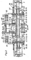
- 1 denotes the machine frame, on which a bracket shaft 5, which is rotatably mounted about the bracket axis 4, is mounted in two pivot bearings 2 and 3.
- Two brackets 6, 7 are mounted on the bracket shaft 5 so as to be longitudinally displaceable but torsionally rigid.
- the brackets can be moved on the bracket shaft 5 by rotating a handwheel which is mounted on the associated bracket and drives a pinion which engages in a rack which is fastened to the bracket shaft 5.
- the wheel 3 for the console 8. 7 The rack is designated 39.
- the rack also serves as an anti-rotation device for the console on the console shaft 5. By moving the consoles, the device is adapted to different widths of the fabric sheet 16.
- the brackets four winding holders 8, 9, 10, stored 1 1, of which the winding holders 8, 10 are arranged coaxially to the winder axis 1 2 and form the winder 13, while the winding holders 9 are disposed 1 1 coaxially to the winder axis 14 and form the winder 15.
- the winding holder 8, 9, 10, 11 are arranged in mutually facing sides of the brackets 6, 7 in pairs facing each other.
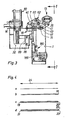
- the fabric web 16 shown in FIGS. 5 a to 5 c extends between the winding holders.
- the fabric web 16 can be simple, as shown in FIG. 4 a; twice, ie doubled, as shown in Figure 4 b; doubled, ie fourfold, as shown in Figure 4 d; placed three times, as shown in Figure 4 c or placed several times.
- the longitudinal fold along the longitudinal folds 18 to 23 serves to wind a wider cloth web according to FIGS. 4 b, c and d onto a winder 25 which is less wide according to the double arrow 24 in order to facilitate storage.
- the web of fabric 16 passes from the upstream machine 17 - apart from the longitudinal folds - into the winding device without any creases and is to be wound up by the winding device to form windings corresponding to the winding 25 and the formation of additional new folds, poses and the like is to be avoided.
- Drive motors 40, 41, 42, 43 assigned to the individual winding holders are used to drive the winders 13 and 15 and, as can be seen in FIGS. 2 and 3, are mounted on the respective console 6 and 7 in addition to the associated winding holders. Each winding holder is thus driven directly by the drive motor assigned to it.
- These drive motors drive clamping heads 44, 45, 46, 47 of the individual winding holders around the respective winding axis 12, 14 while rotating.
- the clamping heads 44, 45, 46, 47 are rotatably and longitudinally displaceable in the associated winding holder.
- the winding holders 8, 9, 10, 11 are of identical design and are arranged mirror-symmetrically to the plane of symmetry 58, which is perpendicular to the plane of the drawing in FIG. 1.
- the W ickelhalter a winder that is, for example, the winding holders 9, 11 of the winder 15, are operated jointly and synchronously. It is not absolutely necessary but expedient to provide a device for synchronizing the rotary movement.
- a coupling shaft 60 which is rotatably mounted on both brackets axially parallel to the winding axis 1 4, is used for the winding holder 9, 1 1 and is connected in a torsionally rigid manner to the two winding holders 9, 11.
- the corresponding coupling shaft for the winding holder 8, 10 is designated 61.
- the drive gear 35 of the drive motor 4 1 meshes with a drive gear 36 of the winding holder 10.
- the drive gear 35 also meshes with a deflection gear 37, which is torsionally rigid but axially displaceable on the clutch shaft 6 1 .
- the opposite winding holder 8 of the same winder 15 is synchronized by the rotational movement of the coupling shaft 61, and thus also by that of the winding holder 10 Deflection gear 1 1 4, which is torsionally rigid and axially displaceable on the coupling shaft 61 and meshes with the drive gear 115 of the drive motor 43.
- the Kupplun g swellen 60, 61 extend beyond the maximum distance of the two brackets 6, 7 and are axially displaceable in these, the L jossverschiebung'der consoles along the K onsolenwelle 5 not to interfere.
- each of these deflecting tubes for example the deflecting tube 63, compare FIG. 1 4, consists of two tube sections 64, 65 which are telescopically placed one above the other in pairs and of which one tube section 64 is fastened to one bracket 7 and the other tube section 65 to the other bracket 6 _is.
- the deflection tube 63 formed by the tube sections can thereby be telescopically pulled apart and plugged together and thus follows the distance between the brackets 6, 7 in its length.
- the deflection tube 63 is provided on its circumference with projecting ribs 67, which extend obliquely to the side in the conveying direction according to arrow 70 from the plane of symmetry 58 and thus from the center of the fabric web 16.
- the ribs each extend only over those outer parts of the tube sections 64, 65 which do not overlap when telescopically pushed together.
- the ribs 67 are, based on the axial direction of the associated deflection axis 7 1 , narrower according to double arrow 73 than 1/10 of the width according to double arrow 74 of the spaces 75, 76 to the adjacent ribs.
- the ribs 67 are formed by two spirals 77, 78.
- deflection rail that has a wrapping surface that is curved in the wrapping direction of the fabric web and that extends over the greatest wrapping angle that occurs.
- the ribs are advantageously provided, but can also be omitted.
- the deflection tube 63 is not rotatable. In a modification, however, the deflection tube 63 can be rotatably mounted about the deflection axis 7 1 , it can be driven to rotate about this axis and can be coupled to the drive of the associated winder for this purpose.
- the deflection tube 63 belongs to the winder 13.
- the deflection tube 6 2 which is designed correspondingly to the deflection tube 63, belongs to the winder 15.
- a deflecting tube 62, 63 or a deflecting element is assigned to each of the winders and is arranged directly upwards of this associated winder.
- the deflection element is arranged in such a way that when the winding is filled to the maximum between the deflection element and the winding there is at least a tolerance distance 174 (see FIG. 5 a), so that the filled winding can rotate past the deflection element without problems.
- the deflection element is arranged so far offset that the tightly drawn web of cloth wrapped around the deflection element with a wrap angle 79 with filled winding of at least 1 0 °, so that the cloth strip 16 even at the maximum g e-for bottled winding not undesirable from the Umienkelement takes off and flutters. If the winding is less filled, as can be seen from FIG. 5 a, a larger wrap angle 79 then results.
- the fabric web 16 is only in contact with the resulting wrap. Following the deflecting element, the fabric web reaches the winding directly. It is wound up freely there and is not under the pressure load of a pressure roller, which loads from the outside on the winding being formed. Such a pressure roller would lead to undesirable wrinkling.
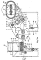
- a board magazine 80 is arranged, which is attached to the machine frame 1.
- the board magazine is ge with a stack of serving as winding cores 81 ge fills, of which the lowest board 82 in each case is released in the direction of arrow 84 with the aid of a distributor 83 assigned to the board magazine 80, whereupon the other boards move downward in the direction of arrow 85.
- the board magazine is adaptable to boards of different lengths according to the width of the fabric sheet 16 being processed.
- the allocator 83 places the dispensed board on the then idle cloth web 16 between the two winder holders 9, 11 of the winder 15 which is in the waiting position.
- the Brettchernmagazin 80 is adaptable to different widths of the cloth web.
- the two magazine cheeks 86, 87 are fastened to cheek supports 31, 32 which can be displaced transversely.
- the cheek beam 31 is mounted on a slide rod 91 and on a parallel threaded spindle 90 in the direction of the console axis 4.
- Threaded spindle 90 and slide rod 91 are mounted in end shields 28, 92 on the machine frame 1.
- the cheek carrier 32 is mounted accordingly.
- the associated hand crank is designated 27, the rod 89 and the threaded spindle 88.
- a separating device is arranged on a cross member 1 84.
- the cross member 184 is mounted on both sides of a hydraulic lifting cylinder 1 85, 186 adjustable in height on the machine frame 1.
- To the cross member 184 are on the cloth web width distributed rotatably drivable knife discs 1 87 disposed, whose circumference is in each case a polygon, and is formed as a cutting edge.
- the cutter discs 1 87 with their cutting a over the entire Tuchbahnoreite extending, horizontal, combined cutting edge, as indicated by the dash-dotted line 1 88 in FIG. 1 In the lower rest position shown in FIGS. 1 and 5, the separating device 180 is ineffective.
- the separating device 180 is arranged that, as can be seen particularly well from FIG. 5 a, it is effective immediately downward of the winder 15 which is in the waiting position.
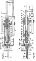
- a drive sleeve 1 13 in ball bearings 03 1, 104 and a rotary sliding bearing 1 12 in the ball bearing 1 02 is rotatable but not longitudinally displaceably mounted.
- the bearing tube 1 07 is mounted for longitudinal displacement.
- a guide wedge is designated, which forces the bearing tube 107 to follow the rotational movements of the driving sleeve 113.
- the drive gear 36 is fastened on the driving sleeve 113.
- the bearing tube 1 07 there is a coupling element 121 which is longitudinally displaceably sliding.
- the push rod 154 of a sword 155 is mounted at the front end of the coupling element.
- the push rod 1 54 is flat and is longitudinally displaceable in a form-fitting longitudinal groove in the coupling element 121, and is supported to the rear on a compression spring 164.
- the longitudinal displacement is limited by an elongated hole 162 in the push rod 154 through which a pin 1 63 of the coupling element is inserted .
- the push rod 154 is torsionally securely guided in a slot 165 of the end face 1 40th
- the clamping head 46 is fastened to the free end of the bearing tube 107.
- the clamping head is shown in FIG. 6 a in its retracted position, in which a wedge cam 1 03 serving as an anti-rotation device and fastened to the clamping head has fallen into a corresponding diametrically opposite receptacle 11 1 of the winder housing 101.
- the clamping head is non-rotatably fixed relative to the winder housing in its retracted position in an angular position defined by the receptacle 111.
- the rotary movement of the clamping head about the winder axis 1 4 is coupled in via a slip clutch (not shown) and via the gear wheel 36.
- the slip clutch serves as compensation when the rotation lock of the wedge cam 108 engages when the rotary motion is running out.
- the drive motor is switched off by a pushbutton switch, not shown, when the wedge cam 108 is engaged.
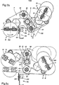
- a collet 130 is mounted in the clamping head with four clamping jaws, of which, however, only two clamping jaws 1 38, 13 9 are visible in FIG. 6.
- the other, not visible clamping jaws are arranged and formed mirror-symmetrically to the mirror symmetry plane 168 from FIG. 8 to the visible clamping jaws 138, 139. All jaws grip on a common level.
- the collet stands so that it grips in the plane of the cloth web 1 6, as is the case for the winder 15 which is provided in FIG. 5 a.
- the two clamping brackets 131, 132 of the collet 130 can be pivoted open and closed about the collet axes 133 and 129.
- the collet is open.
- the two clamping brackets are pivoted against the sword 155 by the rollers 158, 159 under the pressure effect of compression springs 1 34, 1 35.
- the clamping jaws 138, 139 protrude from the end face 140 facing the cloth web 16 and can hold a board serving as a winding core, for example the board 82, together with the edge of the cloth web 16 and the sword 155 when the collet is attached.
- the tensioning brackets 131, 132 consist of two parts which can be moved relative to one another and which are spring-loaded relative to one another by compression springs 160, 16 1 which are designed as plate springs.
- the ickelkernhalter as W serving sword 155 consists not only from the push rod of the two brackets 176, 177 and the cross bar 173 and is formed flat. When extended, it does not extend all the way to the center of the sheet 17 9.
- the two-strap 176, 177 of the S are guided tirnflä- space 140 in slots.
- the coupling element moves forward and with it the sword 155.
- stops 15 3, 166 which are fastened to the rear end of the brackets 176, 177 , strike at the rear of the clamping head 46 - compare FIG. 7 - so that the clamping head must follow the further extension movement of the sword 155 until it finally reaches the position shown in FIG. 6 b, in which the further advance movement of the bearing blade 107 is limited because of a stop 120 of the lacar tube strikes against the rear edge of the driving sleeve 11 3.
- the sword 155 extends parallel to the cloth web over the now inserted board 32 not quite to the cloth web center 17 9 and the jaws 138, 139 ... are still open and embrace the edge of the cloth web 16, the edge of the Boards 82 and the two brackets 176, 177 of the sword 155.
- the bearing tube 107 and the sword 155 can no longer follow a further forward movement of the push rod 57.
- the coupling element 1 21 follows the feed movement and thereby the stationary sword pushes against the force of the compression spring 164 into the coupling element 121 until the bolt 163 limits this insertion movement. This end position is shown in Figure 6 c.
- the operation of the device is as follows.
- One of the machine 17 under tension and the longitudinally folded fabric web 16 first arrives in the tensioning device 1 70 with two deflection rollers 171, 172 and a dancer roller 173 effective in between in a loop, which compensates for irregularities in the belt transport by means of weight or spring loading and a uniform tensile stress Cloth web causes.
- the brackets are in the angular position as shown in FIG. 5 for the console 7, in which the winder 13 is in the winding position and the winder 15 is in the waiting position the winding holder 10 and 11 visible.
- the opposite ickelhalter W are synchronously operated and are coaxial.
- the cloth web 16 runs from the guide roller 172 between the W ickelhaltern of the winder 13 through the return pipe 6 to the third
- the cloth web wraps around the deflection tube 63 on the wrap angle 79 and is thereby stretched outwards by the ribs.
- the fabric web 16 reaches the circumference of the roll, which is rotated in the direction of arrow 175 by the rotary movement of the tensioning heads of the roll 13 and thereby wound up.
- a sensor which then stops the drive of the winder 13.
- the sensor is not shown, nor is the control line for the control functions triggered by the sensor. This also applies to all other sensors and control functions.
- the fabric feed on the machine 17 is switched off and the feed of a board 82 in the board magazine 80 is triggered.
- the board 82 thereby reaches the cloth web 16 between the tensioning heads of the winder 15.
- the tensioning heads of the winder 15 are, due to the anti-rotation, which is formed by the wedge cams 1 08 corresponding to the wedge cams, in an angular position in which they lie flat on the sheet of fabric 16 lying boards 82 can detect with the sheet of fabric 16.
- the tensioning heads of the winder 15 are moved from their offset position according to FIG. 6 a, which they had in the waiting position, into their attached position according to FIG.
- the winder 15 begins its rotational movement in the direction of the arrow 200 and at the same time the cloth web feed in the machine 17 is switched on and the winder 15 begins to wind a new roll on the board 82.
- the console shaft 5 a pivoting movement through 180 ° in the direction of arrow 181, see Figure 5, at the end of the two winders 13 and 1 5 have exchanged their positions starts.
- the winders rotate about the winder axes in the same direction of rotation according to arrow 200 and arrow 175 as the brackets 6, 7 rotate about the console axis according to arrow 181.
- the same direction of rotation of the brackets on the one hand and the winder on the other hand favors the crease-free winding during the turning process of the brackets.
- the winder 13 makes a few slow revolutions in the direction of the arrow 175 and in the process completely winds up the free cloth web 202 which has resulted from the separation process. Once this has been done, the winder 13 releases the filled roll 25 and lets it fall off by retracting the clamping heads with the swords into their offset position according to FIG. 6 a.
- the two winders 13, 15 have exchanged their position according to FIG. 5, the winder 15 winds the started winding completely in the winding position, which the winder 13 holds in FIG. 5, and the winder 13 sees in the waiting position, which the winder 15 holds in FIG. 5.
- FIGS. 10 and 11 A correspondingly modified exemplary embodiment is explained with reference to FIGS. 10 and 11.
- the sword corresponding to the sword 155 is missing and the collet 270 is only in one piece and has two clamping brackets 271, 272 with circularly curved clamping jaws 27 3 , the curvature of which is adapted to a tube piece 274 serving as a winding core.
- a centrally arranged winding core holder 280 is provided, which instead of the push rod 154 has a rod 282, on the free end of which a round clamping block 281 is attached.
- the tensioning block 281 moves into the interior of the tube piece 274 when the winding core holder 280 is extended.
- the rod 282 like the push rod 154, is mounted on the push rod 154 corresponding to the coupling element 121 on the coupling element 233 corresponding to the coupling element 121.
- a clamping mandrel 276 is fastened coaxially to the winder axis 275, which also paws into the tubular piece 274.
- the tensioning block 281 strikes the mandrel 276 and, like the Ouersteg 173, thereby takes the tensioning head back into the rotationally secured position.
- the sword 155 and the swords corresponding to this of the other winding holders can be omitted if the shoe is a sufficiently rigid winding core.
- Parts of the clamping head of a corresponding exemplary embodiment are shown in FIGS. 12 and 13.
- the sword is missing.
- a circular bushing 240 is provided on both sides, through which a mandrel 242, which is parallel to the winder axis 14 and is longitudinally displaceable, projects in the clamping head 241.
- the mandrel 242 is under the load of a compression spring 243 can be pressed back into the Ianere of the clamping head by overcoming the restoring force of this compression spring 243.
- dan arettchek the one who responds If there are holes in its end face, it is additionally held by the clamping mandrel 242 and the opposite, non-visible mandrel, which then engage in these blind holes when the clamping head is attached. If there are no blind holes, the mandrel 242 is not square and is pushed back by the board into the clamping head against the force of the spring 243.
- the collet 244 with its return spring 245 and its tolerance spring 246 is otherwise designed in exactly the same way as the collet 130 from FIG. 6 and also mounted in the clamping head 241 just like this.
- a driver 291 is mounted on the front end of the coupling piece 290 corresponding to the coupling element 121 and is fastened to the clamping head 241.
- the longitudinal displacement of the driver 291 with respect to the coupling element 290 is limited by a pickling corresponding to the bolt 1 63 with an associated longitudinal groove.
- deflection tubes 62, 63 can also be used in devices in which the brackets 6, 7 cannot be adjusted in their spacing.
- This deflection tube is fastened between the fixed brackets 301, 302 and is looped by the cloth web 303.
- the deflection tube 300 has an increasingly thicker diameter toward the center 304, which corresponds to the cloth web rides.
- the two tube halves thus formed are coated with a rib-shaped rib 305, 306.
- the apiral windings extend mirror-symmetrically to one another, with such an incline that the spiral paths are inclined upwards in the direction of the cloth web advance according to arrow 307 and act on the cloth web stretching outwards.
Landscapes
- Replacement Of Web Rolls (AREA)
- Winding Of Webs (AREA)
Priority Applications (1)
| Application Number | Priority Date | Filing Date | Title |
|---|---|---|---|
| AT83106705T ATE25652T1 (de) | 1982-08-07 | 1983-07-08 | Wickelvorrichtung fuer warenbahnen. |
Applications Claiming Priority (4)
| Application Number | Priority Date | Filing Date | Title |
|---|---|---|---|
| DE3229506 | 1982-08-07 | ||
| DE3302291 | 1983-01-25 | ||
| DE19833302291 DE3302291A1 (de) | 1982-08-07 | 1983-01-25 | Verfahren und vorrichtung zum faltenfreien aufmachen von einfach und mehrfach dublierten textilen warenbahnen |
| DE3229506 | 1983-08-07 |
Publications (3)
| Publication Number | Publication Date |
|---|---|
| EP0100462A2 true EP0100462A2 (fr) | 1984-02-15 |
| EP0100462A3 EP0100462A3 (en) | 1985-05-22 |
| EP0100462B1 EP0100462B1 (fr) | 1987-03-04 |
Family
ID=25803605
Family Applications (1)
| Application Number | Title | Priority Date | Filing Date |
|---|---|---|---|
| EP83106705A Expired EP0100462B1 (fr) | 1982-08-07 | 1983-07-08 | Dispositif d'enroulement pour bandes |
Country Status (6)
| Country | Link |
|---|---|
| US (1) | US4500044A (fr) |
| EP (1) | EP0100462B1 (fr) |
| DD (1) | DD210011A5 (fr) |
| DE (2) | DE3302291A1 (fr) |
| DK (1) | DK350783A (fr) |
| ES (1) | ES8404663A1 (fr) |
Cited By (2)
| Publication number | Priority date | Publication date | Assignee | Title |
|---|---|---|---|---|
| DE3629216A1 (de) * | 1986-08-28 | 1988-03-03 | Brueckner Trockentechnik Gmbh | Verfahren und vorrichtung zum wickeln und querschneiden einer warenbahn |
| DE4211858A1 (de) * | 1991-04-08 | 1992-10-15 | Gerber Garment Technology Inc | Verfahren und einrichtung zum kernlosen aufwickeln von flachmaterial |
Families Citing this family (7)
| Publication number | Priority date | Publication date | Assignee | Title |
|---|---|---|---|---|
| IT1230421B (it) * | 1989-08-04 | 1991-10-21 | Cerutti Spa Off Mec | Dispositivo per il bloccaggio automatico di una bobina di materiale nastriforme. |
| JP2659472B2 (ja) * | 1991-04-30 | 1997-09-30 | 松下電器産業株式会社 | 長尺シートの平板巻取り方法及び装置 |
| US5259562A (en) * | 1992-03-09 | 1993-11-09 | Smart-Price International, Inc. | Cloth winder drive |
| US7093786B2 (en) * | 2004-03-03 | 2006-08-22 | First Data Corporation | Take-up cores for flexible materials and methods |
| US10427903B2 (en) | 2016-03-04 | 2019-10-01 | The Procter & Gamble Company | Leading edge device for a surface winder |
| US10442649B2 (en) | 2016-03-04 | 2019-10-15 | The Procter & Gamble Company | Surface winder for producing logs of convolutely wound web materials |
| US10427902B2 (en) | 2016-03-04 | 2019-10-01 | The Procter & Gamble Company | Enhanced introductory portion for a surface winder |
Citations (3)
| Publication number | Priority date | Publication date | Assignee | Title |
|---|---|---|---|---|
| US2272940A (en) * | 1940-03-23 | 1942-02-10 | George A Gerard | Method of winding paper and mechanism therefor |
| DE2250767A1 (de) * | 1972-10-17 | 1974-04-18 | Ebert Kg | Maschine zum herstellen von wickeln aus einer vorher bestimmten anzahl von in einer perforierten bahn aneinanderhaengenden beuteln |
| GB1382136A (en) * | 1972-07-17 | 1975-01-29 | Cuckson Scovill Pty Ltd | Winding machine for spools of textile tape |
Family Cites Families (17)
| Publication number | Priority date | Publication date | Assignee | Title |
|---|---|---|---|---|
| US1390957A (en) * | 1915-01-15 | 1921-09-13 | Measuregraph Co | Cloth winding and measuring machine |
| US1503858A (en) * | 1922-02-20 | 1924-08-05 | Steiner Sales Co | Wet-towel winder |
| US1866471A (en) * | 1929-08-06 | 1932-07-05 | Kiehn Otto Fritz | Textile winding machine |
| DE550093C (de) * | 1929-12-05 | 1932-05-07 | Aeg | Vorrichtung zum selbsttaetigen Regeln der Drehzahl fuer den Antrieb von Aufwickelvorrichtungen |
| US2060360A (en) * | 1932-02-25 | 1936-11-10 | Wood Newspaper Mach Corp | Web roll support |
| DE703893C (de) * | 1939-10-06 | 1941-03-19 | Siemens Schuckertwerke Akt Ges | Selbsttaetige Steuerung der Drehzahl des Wickelbauine |
| DE849086C (de) * | 1951-02-17 | 1952-09-11 | Hans Schaeffler | Couponwickel-Mess- und -Querschneidemaschine |
| US2723717A (en) * | 1953-05-07 | 1955-11-15 | Eddystone Machinery Company | Movable gate carrying rotary knives for cutting cloth on a winding machine |
| US2915257A (en) * | 1954-08-11 | 1959-12-01 | Stamco Inc | Uncoiler with side shift control |
| GB922530A (en) * | 1959-12-30 | 1963-04-03 | Hayden Nilos Ltd | Improvements in or relating to machines for reeling conveyor and like belting |
| US3298624A (en) * | 1964-07-10 | 1967-01-17 | Gloucester Eng Co Inc | Winder |
| US3497150A (en) * | 1967-10-02 | 1970-02-24 | Black Clawson Co | Apparatus for winding web materials |
| DK117398B (da) * | 1967-11-09 | 1970-04-20 | P Hagemeister | Fremgangsmåde og apparat til opvikling af en materialebane. |
| US3866325A (en) * | 1972-11-09 | 1975-02-18 | Lawrence V Wynn | Cloth measuring device |
| DE2317325B2 (de) * | 1973-04-06 | 1977-02-10 | Reifenhäuser KG, 5210 Troisdorf | Wickelmaschine |
| SU480623A1 (ru) * | 1973-07-27 | 1975-08-15 | Белорусское Производственное Объединение Резиновых Технических Изделий | Устройство дл намотки полотна в рулон |
| US3881665A (en) * | 1973-12-28 | 1975-05-06 | Wavin Bv | Device for producing roll-shaped packets of bags of plastic |
-
1983
- 1983-01-25 DE DE19833302291 patent/DE3302291A1/de not_active Withdrawn
- 1983-07-08 DE DE8383106705T patent/DE3369957D1/de not_active Expired
- 1983-07-08 EP EP83106705A patent/EP0100462B1/fr not_active Expired
- 1983-08-01 DK DK350783A patent/DK350783A/da not_active Application Discontinuation
- 1983-08-03 DD DD83253665A patent/DD210011A5/de unknown
- 1983-08-05 ES ES524766A patent/ES8404663A1/es not_active Expired
- 1983-08-08 US US06/521,505 patent/US4500044A/en not_active Expired - Fee Related
Patent Citations (3)
| Publication number | Priority date | Publication date | Assignee | Title |
|---|---|---|---|---|
| US2272940A (en) * | 1940-03-23 | 1942-02-10 | George A Gerard | Method of winding paper and mechanism therefor |
| GB1382136A (en) * | 1972-07-17 | 1975-01-29 | Cuckson Scovill Pty Ltd | Winding machine for spools of textile tape |
| DE2250767A1 (de) * | 1972-10-17 | 1974-04-18 | Ebert Kg | Maschine zum herstellen von wickeln aus einer vorher bestimmten anzahl von in einer perforierten bahn aneinanderhaengenden beuteln |
Cited By (3)
| Publication number | Priority date | Publication date | Assignee | Title |
|---|---|---|---|---|
| DE3629216A1 (de) * | 1986-08-28 | 1988-03-03 | Brueckner Trockentechnik Gmbh | Verfahren und vorrichtung zum wickeln und querschneiden einer warenbahn |
| DE4211858A1 (de) * | 1991-04-08 | 1992-10-15 | Gerber Garment Technology Inc | Verfahren und einrichtung zum kernlosen aufwickeln von flachmaterial |
| US5289669A (en) * | 1991-04-08 | 1994-03-01 | Gerber Garment Technologies, Inc. | Coreless winder and method of use |
Also Published As
| Publication number | Publication date |
|---|---|
| DE3369957D1 (en) | 1987-04-09 |
| DK350783D0 (fr) | 1983-08-01 |
| EP0100462B1 (fr) | 1987-03-04 |
| EP0100462A3 (en) | 1985-05-22 |
| DK350783A (da) | 1984-02-08 |
| ES524766A0 (es) | 1984-05-01 |
| ES8404663A1 (es) | 1984-05-01 |
| DE3302291A1 (de) | 1984-03-08 |
| DD210011A5 (de) | 1984-05-30 |
| US4500044A (en) | 1985-02-19 |
Similar Documents
| Publication | Publication Date | Title |
|---|---|---|
| DE3737504C2 (fr) | ||
| DE2127128C3 (de) | Verfahren zum Wickelwechsel in einer Vorrichtung zum Aufwickeln einer mit querverlaufenden Perforationen versehenen Bahn und Vorrichtung zum Durchführen des Verfahrens | |
| EP0132727B1 (fr) | Dispositif pour le découpage et l'enroulement automatique de tissus | |
| DE2847556A1 (de) | Revolverkopf-aufwickelmaschine fuer bandfoermiges material | |
| AT398561B (de) | Wickelmaschine zum gleichzeitigen achslosen aufwickeln der streifen einer längsgeteilten bahn auf wenigstens zwei wickelrollen | |
| DE3737503A1 (de) | Rollenschneidemaschine | |
| EP0968919B1 (fr) | Procédé et dispositif d'enveloppement d'objets quadrangulaires avec un matériau d'emballage sous forme de bande | |
| DE3736395A1 (de) | Vorrichtung zum ab- oder aufrollen von bahn- oder bandfoermigen materialien | |
| DE4401804A1 (de) | Verfahren zum Aufwickeln einer laufenden Bahn sowie Wickelmaschine zum Durchführen des Verfahrens | |
| EP0100462B1 (fr) | Dispositif d'enroulement pour bandes | |
| DE3723827A1 (de) | Verfahren zum aufwickeln von ohne unterbrechung zugefuehrtem wickelgut auf mehrere wickelkerne sowie doppeltragwalzenroller | |
| DE4304469A1 (de) | Wickelvorrichtung mit Rollenwechseleinrichtung für aufzuwickelndes bandförmiges Wickelgut | |
| DE1474987A1 (de) | Vorrichtung zum kontinuierlichen Abwickeln und Miteinanderverbinden von bahnfoermigem Material,wie z.B. Papier- und Kunststoffbahnen | |
| DE1948727A1 (de) | Aufwickelvorrichtung fuer bahnfoermiges Gut | |
| EP1108669A2 (fr) | Dispositif d'enroulage de bobines, en particulier pour une refendeuse | |
| DE3914776A1 (de) | Verfahren und vorrichtung zum aufwickeln und querschneiden einer laufenden warenbahn | |
| EP0191809B1 (fr) | Dispositif d'enroulement d'articles en bandes | |
| DE3440107C2 (fr) | ||
| EP0514334B1 (fr) | Installation de compression d'une machine d'enveloppement pour fabriquer des paquets cylindriques d'articles d'imprimerie | |
| DE19754106A1 (de) | Vorrichtung und Verfahren zum Einziehen einer Bedruckstoffbahn | |
| EP0853579B1 (fr) | Machine automatique a emballer avec changement automatique du materiau d'emballage | |
| DE19727325A1 (de) | Wickeleinrichtung für eine Materialbahn, insbesondere für eine Rollenschneidvorrichtung | |
| EP1280725B1 (fr) | Dispositif et procede destines a tendre une bande de materiau plate a transporter au moyen d'une difference de vitesse de rotation | |
| DE19937486B4 (de) | Transportfahrzeug zur Entnahme eines Warenbaums aus einer Webmaschine, Schneidvorrichtung für das Transportfahrzeug zum Abtrennen einer Warenbahn und Verfahren zur Entnahme des Warenbaums aus der Webmaschine | |
| DE2400016C3 (de) | Wickelmaschine zum Herstellen von Wickelrollen aus Kunststoffsäcken |
Legal Events
| Date | Code | Title | Description |
|---|---|---|---|
| PUAI | Public reference made under article 153(3) epc to a published international application that has entered the european phase |
Free format text: ORIGINAL CODE: 0009012 |
|
| AK | Designated contracting states |
Designated state(s): AT BE CH DE FR GB IT LI LU NL SE |
|
| PUAL | Search report despatched |
Free format text: ORIGINAL CODE: 0009013 |
|
| AK | Designated contracting states |
Designated state(s): AT BE CH DE FR GB IT LI LU NL SE |
|
| 17P | Request for examination filed |
Effective date: 19850511 |
|
| GRAA | (expected) grant |
Free format text: ORIGINAL CODE: 0009210 |
|
| AK | Designated contracting states |
Kind code of ref document: B1 Designated state(s): AT BE CH DE FR GB IT LI LU NL SE |
|
| PG25 | Lapsed in a contracting state [announced via postgrant information from national office to epo] |
Ref country code: SE Effective date: 19870304 |
|
| REF | Corresponds to: |
Ref document number: 25652 Country of ref document: AT Date of ref document: 19870315 Kind code of ref document: T |
|
| REF | Corresponds to: |
Ref document number: 3369957 Country of ref document: DE Date of ref document: 19870409 |
|
| ITF | It: translation for a ep patent filed |
Owner name: KARAGHIOSOFF GIORGIO |
|
| ET | Fr: translation filed | ||
| PG25 | Lapsed in a contracting state [announced via postgrant information from national office to epo] |
Ref country code: LU Free format text: LAPSE BECAUSE OF NON-PAYMENT OF DUE FEES Effective date: 19870731 |
|
| PGFP | Annual fee paid to national office [announced via postgrant information from national office to epo] |
Ref country code: NL Payment date: 19870731 Year of fee payment: 5 |
|
| PLBE | No opposition filed within time limit |
Free format text: ORIGINAL CODE: 0009261 |
|
| STAA | Information on the status of an ep patent application or granted ep patent |
Free format text: STATUS: NO OPPOSITION FILED WITHIN TIME LIMIT |
|
| 26N | No opposition filed | ||
| PG25 | Lapsed in a contracting state [announced via postgrant information from national office to epo] |
Ref country code: GB Effective date: 19880708 Ref country code: AT Effective date: 19880708 |
|
| PG25 | Lapsed in a contracting state [announced via postgrant information from national office to epo] |
Ref country code: LI Effective date: 19880731 Ref country code: CH Effective date: 19880731 Ref country code: BE Effective date: 19880731 |
|
| BERE | Be: lapsed |
Owner name: SCHNELL HEINRICH Effective date: 19880731 |
|
| PG25 | Lapsed in a contracting state [announced via postgrant information from national office to epo] |
Ref country code: NL Effective date: 19890201 |
|
| NLV4 | Nl: lapsed or anulled due to non-payment of the annual fee | ||
| GBPC | Gb: european patent ceased through non-payment of renewal fee | ||
| REG | Reference to a national code |
Ref country code: CH Ref legal event code: PL |
|
| PGFP | Annual fee paid to national office [announced via postgrant information from national office to epo] |
Ref country code: FR Payment date: 19930625 Year of fee payment: 11 |
|
| PGFP | Annual fee paid to national office [announced via postgrant information from national office to epo] |
Ref country code: DE Payment date: 19930628 Year of fee payment: 11 |
|
| PG25 | Lapsed in a contracting state [announced via postgrant information from national office to epo] |
Ref country code: FR Effective date: 19950331 |
|
| PG25 | Lapsed in a contracting state [announced via postgrant information from national office to epo] |
Ref country code: DE Effective date: 19950401 |
|
| REG | Reference to a national code |
Ref country code: FR Ref legal event code: ST |