EP0776313B1 - Procede et appareil ameliores d'enroulement d'une bande circulaire sur un rouleau - Google Patents
Procede et appareil ameliores d'enroulement d'une bande circulaire sur un rouleau Download PDFInfo
- Publication number
- EP0776313B1 EP0776313B1 EP95930170A EP95930170A EP0776313B1 EP 0776313 B1 EP0776313 B1 EP 0776313B1 EP 95930170 A EP95930170 A EP 95930170A EP 95930170 A EP95930170 A EP 95930170A EP 0776313 B1 EP0776313 B1 EP 0776313B1
- Authority
- EP
- European Patent Office
- Prior art keywords
- web
- reel spool
- wound
- support
- reel
- Prior art date
- Legal status (The legal status is an assumption and is not a legal conclusion. Google has not performed a legal analysis and makes no representation as to the accuracy of the status listed.)
- Expired - Lifetime
Links
Images


Classifications
-
- B—PERFORMING OPERATIONS; TRANSPORTING
- B65—CONVEYING; PACKING; STORING; HANDLING THIN OR FILAMENTARY MATERIAL
- B65H—HANDLING THIN OR FILAMENTARY MATERIAL, e.g. SHEETS, WEBS, CABLES
- B65H19/00—Changing the web roll
- B65H19/22—Changing the web roll in winding mechanisms or in connection with winding operations
-
- B—PERFORMING OPERATIONS; TRANSPORTING
- B65—CONVEYING; PACKING; STORING; HANDLING THIN OR FILAMENTARY MATERIAL
- B65H—HANDLING THIN OR FILAMENTARY MATERIAL, e.g. SHEETS, WEBS, CABLES
- B65H18/00—Winding webs
- B65H18/08—Web-winding mechanisms
- B65H18/26—Mechanisms for controlling contact pressure on winding-web package, e.g. for regulating the quantity of air between web layers
-
- B—PERFORMING OPERATIONS; TRANSPORTING
- B65—CONVEYING; PACKING; STORING; HANDLING THIN OR FILAMENTARY MATERIAL
- B65H—HANDLING THIN OR FILAMENTARY MATERIAL, e.g. SHEETS, WEBS, CABLES
- B65H19/00—Changing the web roll
- B65H19/22—Changing the web roll in winding mechanisms or in connection with winding operations
- B65H19/2207—Changing the web roll in winding mechanisms or in connection with winding operations the web roll being driven by a winding mechanism of the centre or core drive type
-
- B—PERFORMING OPERATIONS; TRANSPORTING
- B65—CONVEYING; PACKING; STORING; HANDLING THIN OR FILAMENTARY MATERIAL
- B65H—HANDLING THIN OR FILAMENTARY MATERIAL, e.g. SHEETS, WEBS, CABLES
- B65H19/00—Changing the web roll
- B65H19/22—Changing the web roll in winding mechanisms or in connection with winding operations
- B65H19/2238—The web roll being driven by a winding mechanism of the nip or tangential drive type
- B65H19/2253—The web roll being driven by a winding mechanism of the nip or tangential drive type and the roll being displaced during the winding operation
-
- B—PERFORMING OPERATIONS; TRANSPORTING
- B65—CONVEYING; PACKING; STORING; HANDLING THIN OR FILAMENTARY MATERIAL
- B65H—HANDLING THIN OR FILAMENTARY MATERIAL, e.g. SHEETS, WEBS, CABLES
- B65H2301/00—Handling processes for sheets or webs
- B65H2301/30—Orientation, displacement, position of the handled material
- B65H2301/31—Features of transport path
- B65H2301/316—Features of transport path of web roll
- B65H2301/3162—Features of transport path of web roll involving only one plane containing the roll axis
- B65H2301/31622—Features of transport path of web roll involving only one plane containing the roll axis rectilinear transport path
-
- B—PERFORMING OPERATIONS; TRANSPORTING
- B65—CONVEYING; PACKING; STORING; HANDLING THIN OR FILAMENTARY MATERIAL
- B65H—HANDLING THIN OR FILAMENTARY MATERIAL, e.g. SHEETS, WEBS, CABLES
- B65H2301/00—Handling processes for sheets or webs
- B65H2301/40—Type of handling process
- B65H2301/41—Winding, unwinding
- B65H2301/417—Handling or changing web rolls
- B65H2301/4171—Handling web roll
- B65H2301/4173—Handling web roll by central portion, e.g. gripping central portion
- B65H2301/41734—Handling web roll by central portion, e.g. gripping central portion involving rail
-
- B—PERFORMING OPERATIONS; TRANSPORTING
- B65—CONVEYING; PACKING; STORING; HANDLING THIN OR FILAMENTARY MATERIAL
- B65H—HANDLING THIN OR FILAMENTARY MATERIAL, e.g. SHEETS, WEBS, CABLES
- B65H2301/00—Handling processes for sheets or webs
- B65H2301/40—Type of handling process
- B65H2301/41—Winding, unwinding
- B65H2301/417—Handling or changing web rolls
- B65H2301/418—Changing web roll
- B65H2301/4181—Core or mandrel supply
- B65H2301/41816—Core or mandrel supply by core magazine within winding machine, i.e. horizontal or inclined ramp holding cores
-
- B—PERFORMING OPERATIONS; TRANSPORTING
- B65—CONVEYING; PACKING; STORING; HANDLING THIN OR FILAMENTARY MATERIAL
- B65H—HANDLING THIN OR FILAMENTARY MATERIAL, e.g. SHEETS, WEBS, CABLES
- B65H2408/00—Specific machines
- B65H2408/20—Specific machines for handling web(s)
- B65H2408/23—Winding machines
- B65H2408/236—Pope-winders with first winding on an arc of circle and secondary winding along rails
-
- B—PERFORMING OPERATIONS; TRANSPORTING
- B65—CONVEYING; PACKING; STORING; HANDLING THIN OR FILAMENTARY MATERIAL
- B65H—HANDLING THIN OR FILAMENTARY MATERIAL, e.g. SHEETS, WEBS, CABLES
- B65H2408/00—Specific machines
- B65H2408/20—Specific machines for handling web(s)
- B65H2408/23—Winding machines
- B65H2408/237—Winding machines with substantially continuous horizontal movement of roll support, e.g. Metso-Type
Definitions
- This invention relates to the reeling of a wound web roll. More particularly, this invention relates to an improved method and apparatus for reeling a wound web roll which is maintained under torsion, and preferably nip pressure, and web tension substantially at all times during its formation.
- this invention relates to an improved reel on a papermaking machine, and an improved method of reeling paper onto a reel spool, wherein, in a preferred embodiment, the paper is reeled into a wound web roll with its upper side, as produced on the papermaking machine, facing outwardly as it is wound into the wound web roll, and wherein the reel spool is continuously supported on a pair of spaced, horizontally disposed rails during the reeling process while a support drum can selectively nip, and partially support from below, the paper web roll being wound, by substantially vertical translational movement of the support drum.
- the said US-A-3,743,199 discloses a method of reeling a traveling web having upper and lower sides into a wound web roll on a reel apparatus having a pair of spaced, horizontally disposed rails, wherein the reel spool is transferred from primary to secondary arms, and the torque is generally applied after the wound paper roll was transferred onto the secondary arms.
- the reel spool was transferred from primary to secondary arms, and the nip of the reel spool onto a support drum was not accomplished smoothly or uniformly, or maintained with uniform or controlled nip pressure. Further, torque was typically not applied to the reel spool, on which the traveling paper web was being wound, but, when torque was applied, it was generally applied after the wound paper roll was transferred onto the secondary arms.
- the object of the invention is to provide an optimal method and apparatus which allow a complete combination of torque, nip and tension over a wide range of operating parameters, in particular wherein torque can be applied to the reel spool during most, or all, of its path of travel from the time it is loaded into the apparatus until the time the paper web roll has been completed and wherein the path of reel spool travel is made as smooth as possible.
- the reel spools are rotatively supported by bearings at each end of the reel spool which bearings, in turn, are supported in rolling engagement by a pair of laterally spaced, substantially horizontally disposed rails.
- These rails are mounted in a frame which also serves to mount two pair of movable preferably pivoted, beams, with one beam of each pair of beams disposed on either side of the reel apparatus. Both pairs of beams are mounted above the support rails, and each of the pairs of beams operate independently of the other pair of beams about their pivot mountings.
- All of the beams are mounted above the reel spool bearings such that the two beams on each side of the apparatus (i.e., one beam from each pair of beams) are disposed near an end of the reel spool in operating position, and are also disposed above one of the support rails which support the reel spool bearings.
- a carriage is mounted to each beam in a manner to allow it to travel longitudinally for a substantial distance along the length of the beam.
- the two carriages on each pair of beams are thus adapted to engage an empty reel spool at the reel spool storage end of the reel apparatus and, in a preferred embodiment, transfer the reel spool longitudinally in a direction from the so-called dry end of the papermaking machine to the so-called wet end of the papermaking machine.
- the traveling paper web which is produced at the dry end of the papermaking machine is passed over a segment of the peripheral surface of a support drum which is mounted on a frame so as to be disposed beneath the support rails.
- the support drum is mounted to move translationally upwardly and downwardly, whether vertically up and down, at an angle to the vertical along a straight path, or pivotally along an arc, so as to move translationally to engage a reel spool along a nip line of contact. Since the beams are mounted above the reel spool bearings on the support rails, the carriages for engaging and moving, and bearing housings rotatively supporting, the reel spools are also above the rails and reel spool bearings.
- the support drum to be made smaller in diameter, and consequently lighter, so as to be capable of being moved into, and out of, nipping engagement with the web being wound into a roll on the reel spool relatively easily and quickly by lifting devices, such as pneumatic or hydraulic cylinders, or ball-screw actuators, or the like.
- lifting devices such as pneumatic or hydraulic cylinders, or ball-screw actuators, or the like.
- the relatively light construction and weight of the smaller diameter support drum permits any nip loading between the support drum and the paper web roll being wound to be controlled more accurately and in smaller increments.
- any pressure sensitive coating on the paper web is not scuffed at its interface with the relatively stable last ply of the paper web wound on the roll.
- Some paper mills prefer to have their coated paper, whether the coating is pressure sensitive or not, applied to the upper side of the paper web as it is produced on the papermaking machine. This upper side is then desired to be wound on the reel with the coated side facing out for subsequent processing, such as being printed.
- the method and apparatus of this invention provide such a finished wound paper web roll with controlled internal wound web tension.
- a feature of this invention is the provision of at least one pivoted pair of beams for supporting a corresponding pair of carriages for moving the reel spool translationally along a pair of reel support rails during the winding process, which pair of beams is mounted above the support rails and reel spool bearings.
- Another feature and advantage of this invention is the ability to wind the paper web onto the reel spool from start to finish while the reel spool is maintained in a substantially horizontal path of travel.
- Still another feature and advantage of this invention is the ability to utilize a relatively small diameter support drum in conjunction with the engagement of the support drum with a relatively small diameter reel spool along a nip line of contact therebetween while the reel spool is supported on a pair of spaced, horizontally disposed rails.
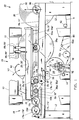
- the reel apparatus generally designated with the numeral 10 , includes a frame 12 on which are mounted a pair of spaced, horizontally disposed rails 14,14' for supporting reel spools 16a,16b,16c,16d from a spool storage area, generally designated with the numeral 18 , at one end of the apparatus, to a finished wound paper web roll 20 at the other end of the reel apparatus, generally designated with the number 22 , where the wound web roll is stored for removal.
- the reel apparatus of this invention generally comprises components which are structurally similar at both ends, such as in the case of a reel spool, or on both sides of the apparatus, such as in the case of the frame work, including the rails and support beams, which will be discussed later.
- the prime mark will be used to distinguish between different ends, or sides, of a component, such as each end of a single reel spool, and alphabetical subscripts will be used to distinguish corresponding like elements, such as reel spools.
- One beam from each pair of beams is pivoted to the frame, such as at pivot 28 in Figure 1, near the reel spool storage end, or downstream end of the reel on each side of the apparatus.
- Mounted to each beam of each pair of beams 24,24', 26,26' is a carriage 30,30' and 30a,30a' which is so constructed and arranged as to move along on ball screws, linear bearing slots, flanges, or the like, in the beam, and generally designated with the numeral 31,31' , on rollers, or lubricated ways, or the like, on the carriages.
- One carriage on either side of the apparatus is arranged to cooperate with another carriage on the other side of the apparatus, with each carriage mounted on a beam of a corresponding pair of beams, so that they can engage a reel spool for translational movement in the direction longitudinally along the support beams.
- the reel spool is actually rotatively supported on the support rails in bearing housings which roll on the support rails.
- each beam On the pivoted end of each beam is an actuator, such as a pneumatic or hydraulic cylinders 32,32',33,33' ( Figure 8), but which might also comprise a ball screw or a chain and a driven sprocket arrangement, which has its extendible end connected to the carriage mounted on its support beam and the fixed end attached to the support beam.
- an actuator such as a pneumatic or hydraulic cylinders 32,32',33,33' ( Figure 8)
- Figure 8 On the pivoted end of each beam is an actuator, such as a pneumatic or hydraulic cylinders 32,32',33,33' ( Figure 8), but which might also comprise a ball screw or a chain and a driven sprocket arrangement, which has its extendible end connected to the carriage mounted on its support beam and the fixed end attached to the support beam.
- the support beams on either side of the apparatus extend parallel to one another, and are spaced above the corresponding rail on each side of the apparatus, and coextend in the same direction with the rail on each side of the
- the carriages in this invention are mounted beneath the support beams, and are mounted to travel longitudinally along the bottom sides thereof, to engage the reel spools, which are rotatively mounted in bearing housings which, in turn, are adapted to roll along rails 14,14' for applying force to the reel spools, preferably through their bearing housings, to either nip them with the support drum, to be described later, or to move the reel spools and the web roll being wound thereon along the rails, or to maintain tension in the web between the support drum and the paper web roll being wound on the reel spool, or any combination of these operations.
- Rails 14,14' are spaced apart, parallel and extend linearly horizontally from a spool storage end 18 to a finished wound paper web roll end 22 .
- Rails 14,14' extend horizontally linearly in a continuous line throughout their operational length.
- Figure 1 also shows spool stop apparatus, generally designated with the numerals 36,36a , for both maintaining empty spools in a ready position in the reel spool storage area, and for releasing a single spool at a time to be released and positioned into an initial position 34 ( Figure 3) by actuation of a fluid cylinder 38 .
- spool stop apparatus generally designated with the numerals 36,36a , for both maintaining empty spools in a ready position in the reel spool storage area, and for releasing a single spool at a time to be released and positioned into an initial position 34 ( Figure 3) by actuation of a fluid cylinder 38 .
- Such apparatus for holding empty reel spools and releasing them one at a time is known in the industry and will not be discussed further.
- Figure 1 illustrates a so-called web turn-up apparatus 40 which pilots in the direction of double-headed arrow 42 into, and out of, a position where it is disposed about a portion of the periphery of an empty reel spool in the initial position 34 for intercepting and guiding the on-coming severed end of the paper web about the reel spool to wrap the reel spool to commence winding the web on it.
- Such turn-up devices often utilize a plurality of compressed air streams to direct the on-coming paper web into wrapping engagement with the reel spool.
- the position of the turn-up apparatus during the web turn-up procedure is also shown in Figure 3.
- FIGs 2-5 illustrate the sequence of a wound paper web roll 20a nearing its completion, as shown in Figure 2, while, in Figure 3, the paper roll being wound has been finished and a new reel spool 16b is shown in the initial position where the severed web is initially wrapped onto the new reel spool.
- the paper web roll being wound is shown in its alternate winding position 46 where it is not nipped with support drum 44 , but is turned solely by a centerwind drive, to be described later.
- the paper web roll being wound is driven by a combination of a centerwind drive and the nipping engagement of the support drum and the paper web roll.
- the empty reel spool In the initial position 34 , which extends for a short distance or span along the support rails from slightly out of nipping engagement with the support drum, in the direction of empty reel spool storage, to nipping engagement N with the support drum, the empty reel spool can either be not in nipping engagement with the support drum, or in nipping engagement N with the support drum, as shown in Figure 3.
- the finished wound web roll 20 has been moved downstream to the wound web roll storage area 22 while the newly-started reel spool 16b has been moved by its carriages, not shown in this figure, along its horizontal path while being supported on the rails through its bearing housings and over the top of the peripheral surface of the support drum 44 .
- the web roll 20b being wound has been moved translationally to the winding position 46 where, in one preferred embodiment, it is maintained in nipping engagement with the support drum which is moved substantially vertically in the direction of double-headed arrow 48 to maintain the desired nip pressure N 1 , or its position ⁇ 1 , such as shown in Figure 3, or both.
- the angular position ⁇ 1 is the angle from a vertical plane P through the rotational axis 50 of the support drum to a plane having both axis 50 and the rotational axis 51 of the paper web roll 20a being wound.
- Figures 6 and 7 illustrate drive apparatus for rotatively driving both the reel spools and the support drum to control both their absolute speeds and any desired speed differential between the reel spool on which the paper web roll is being wound and the support drum in order to provide the desired web tension being wound into the wound web roll.
- the reel spools can be driven by applying torque from separate motors 52,52a mounted on rails 54,54' and 56,56' which co-extend with the rails 14,14' on which the reel spools are rotatively supported in their bearing housings 17,17' which roll on the rails.
- alternate reel spools can be engaged by extendable/retractable couplings 58,58a attached to the drive shafts 60,60a of the respective motors in a manner such that an empty reel spool can be brought into its initial position and rotatively brought up to speed by one drive motor, while the drive motor on the other side of the apparatus can be completing the winding of a web roll and continue to drive the wound web roll after it has left either nipping engagement with the support drum, or proximity with the support drum, and moved to its storage position on the support rails.
- the support drum 44 can also be continuously driven by motor 62 through a splined shaft 64 which utilizes universal couplings 66,66' to maintain continuous driving engagement of the support drum regardless of its vertical position in the apparatus.
- the support drum may also be driven by a journal mounted gear box, or by belt drive.
- the support drum is movable substantially vertically to engage the reel spool/wound web roll along a nip line of contact N 1 therebetween.
- Such vertical movement can be either absolutely vertical, linear along an angle to a vertical plane, or along an arc, such as if the support drum is mounted on a pair of arms to move through an arcuate path of travel. These alternatives are collectively considered to be substantially vertical.
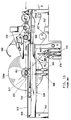
- Figure 8 illustrates the preferred arrangement for mounting the carriages on two pairs of co-axially pivoted support beams 24,24' and 26,26' on which the carriages for guiding the bearing housings 17,17' and 17a,17a' of successive reel spools are mounted to roll, or otherwise move, longitudinally therealong and to bypass one another as the carriages which have moved a finished wound web roll to its storage position move past the carriages which are supporting a reel spool in its initial, or winding, positions to return to the supply of reel spools and receive an empty reel spool from the spool stop apparatus 36 ( Figure 1).
- FIG 9 a prior art Pope-type reeling apparatus is shown which utilizes a pair of primary arms 68,68' to initially receive a new reel spool and to bring it into nipping engagement with the support drum 70 after which the web is threaded into the nip to wrap the reel spool, and the reel spool on which the on-coming web is wound is moved downwardly over the surface of the support drum 70 in nipping engagement therewith, after which it is deposited on horizontal rails 72,72' .
- the secondary arms 74,74' engage the reel spool and hold it into a nipping engagement with the support drum as the wound web roll increases in diameter.
- wound web roll and empty reel spools which are common to any type of reel apparatus, are designated with corresponding numerals, but in a 200 series.
- wound web roll in the Pope reel is designated 220 .
- Figure 10 illustrates the reel apparatus which is shown, described and claimed in U.S. Patent Application 5,370,327. Corresponding elements have corresponding numerals, but in a 300 series. While the apparatus in this referenced patent application works well, it requires a support drum 344 which is relatively large in diameter in order to come into nipping engagement with the reel spool in the initial position due to the support of the reel spools by the carriages disposed beneath the reel spools.
- the weight of the support drum is commensurate with its relatively large diameter, and this requires the hydraulic cylinders 376,378 for providing macro and micro movement and adjustment, respectively, of the support drum into position to be quite large to the extent that such macro and micro movement and adjustment is difficult to effect and control, particularly with respect to fine tuning the nip N 2 at frequent intervals and in small increments, during operation.
- the on-coming web W traveling from the upstream direction of the so-called wet end of the papermaking machine towards the downstream direction of the so-called dry end of the papermaking machine, in the direction of arrow 80 , and is directed over a plurality of guide rolls 82,82a,82b onto the support drum such that its upper side W U comes into supporting contact with a segment of the peripheral surface of the support drum and is, in turn, wrapped onto an empty reel spool 16b by action of the turn-up apparatus 40 , which has been moved downwardly ( Figure 3) to a position of spaced adjacency with the spool 16b to initiate the wrapping of the on-coming web onto the reel spool.
- the web turn-up apparatus 40 initiates the turn-up only after the new reel spool is brought from the storage position to the initial position and nipped N with the support drum. At this location, the reel spool is also being torqued by a motor 52,52a .
- the upper side W U is facing outwardly
- the lower side W L is wrapped facing inwardly.
- the new, empty reel spool had previously been moved into its initial position 34 from the reel spool storage area 18 of the apparatus which contains a supply of reel spools 16b,16c,16d .
- the empty reel spool 16a In its initial position, which is spaced slightly downstream from nipping engagement with the support drum 44 , the empty reel spool 16a is engaged by the carriages 30,30' which are slidably mounted on the bottom of a pair of support beams 24,24' which are pivoted at 28 downstream of the apparatus.
- Reel spool 16a like the other reel spools, is rotatively mounted in a corresponding pair of rotatable bearing housings 17a,17a' which rotatively support the reel spools for translational movement along the support rails 14,14' .
- Carriages 30,30' are acted upon for reciprocal movement along their support beams by actuation of power cylinders 32,32' to move longitudinally along their support beams in a direction substantially parallel with the rails supporting the reel spools.
- the reel spools are rotatively supported on the rails 14,14' , but are moved by the carriages which are mounted on the pivoted support beams. Since engagement of the reel spool bearing housings by the carriages need only be to the extent necessary to reciprocate them while they are supported on the rails, the support beams need not be exactly parallel with the support rails in operation.
- the reel spool 16a is engaged by one of the differential drive motors through its coupling on one end of the reel spool on either the front or the back side of the reel apparatus.
- the reel spool is thereby brought up to speed in the initial position to commence winding the on-coming web onto the reel spool with a desired amount of tension as provided by the reel spool drive motor 52 or 52a which may operate in conjunction with a differential speed between it and the motor 62 rotatively driving the support drum 44 .
- the newly started reel spool can optionally be either brought into nipping engagement N 1 with the support drum, or remain slightly spaced from the support drum.
- the torque applied to the reel spool operating in conjunction with the torque applied to the support drum, and, if applicable, the nip N 1 between the web building into a roll on the reel spool and the support drum, operate to build a desired amount of web tension into the web roll being wound.
- the carriages 30,30' move the web roll into a winding position, generally designated with the numeral 46 , which is upstream of the apparatus in a direction against the direction of the on-coming paper web.
- this winding position 46 which is shown in spaced adjacency with the support drum in Figure 2, and which is shown in nipping engagement N 1 with the support drum in Figure 5, the web roll is wound to its finished diameter.
- the support drum 44 In moving from the initial position to the winding position, if it is desired to maintain nipping engagement with the newly started paper web roll, the support drum 44 is moved up and/or down in the direction of double-headed arrow 48 to provide the desired amount of nip N 1 , and maintain the nip, with the web roll being wound, regardless of the increasing diameter of the web roll being wound, as the carriages move the reel spool, and the web roll being wound thereon, horizontally along the linearly extending horizontal path of the support rails from the initial position to the winding position by the rolling motion of the bearing housings 17,17' supporting the reel spool on the support rails 14,14' .
- the actuation cylinders 32,32'; 33,33' can also assist in maintaining or adjusting the nip between the web roll being wound and the support drum. This can be done by controlling the positions of the carriages on the support rails.
- actuation cylinders 33,33' on the other pair of pivoted support beams 26,26' are actuated to move their pair of carriages 30a,30a' to move a new/empty reel spool first into initial position and then through the cycle of winding position with optional nipping engagement with the support drum, and then into storage position from which it is removed from the apparatus as shown by arrow 90 .
- a pair of hydraulic cylinders 89,89' are actuated to lift the pivoted support beams 26,26' about their pivot 28 to lift carriages 30a,30a' from engagement with the bearing housings 17,17' to permit the wound web roll to be moved to the storage area for removal.
- the support drum 44 By supporting the carriages beneath pivotally mounted beams which are located above the support rails, on which the bearing housings of the reels are supported for rolling movement horizontally from at least the initial position to the winding position where the paper web roll is finished being wound, the support drum 44 can be brought into nipping engagement with the reel spool, and the paper web being wrapped on the reel spool, when the diameter of the support drum is quite small. This is because the carriages which move the reel spools translationally, laterally in their horizontal path of travel on the support rails 14,14' are positioned above the bearing housings (i.e. reel spool bearings) which rotatively support the reel spools on the support rails.
- the bearing housings i.e. reel spool bearings
- the relatively small diameter of the support drum permits it to be moved relatively more easily, more quickly and in smaller, more controlled increments of nip load between the support drum and the paper web roll being wound. This permits the winding of pressure-sensitive papers, such as carbonless copy paper and other coated or fine papers.
Abstract
Claims (6)
- Procédé de bobinage d'une bande (W) qui défile possédant des côtés supérieur et inférieur (WU, WL) pour obtenir un rouleau de bande à l'état enroulé (20) sur un appareil de bobinage (10) comportant un bâti (12) et une paire de rails espacés (14, 14') disposés à l'horizontale, une paire de moyens de poutrelles (24, 24') montés en mobilité, sur lesquels est montée une paire correspondante de chariots (30, 30') pour venir se mettre en contact avec et déplacer les tambours de bobinage (16a, 16b, ...) en direction longitudinale le long des moyens de poutrelles, et un mandrin de support (44) qui est monté pour effectuer un mouvement de translation essentiellement vertical, comprenant les étapes consistant à:1) déplacer un tambour de bobinage (16a, 16b, ...) possédant un axe de rotation jusqu'à une position initiale (34) où il est supporté en rotation (17a, 17b, ...; 14, 14') sur les rails (14, 14') par la mise en contact des tambours de bobinage (16a, 16b, ...) à partir du haut avec les chariots (30, 30');2) amener la bande qui défile en contact de support avec un segment de la surface périphérique d'un mandrin de support (44) mobile en translation et entraíné en rotation, un côté prédéterminé de la bande étant orienté vers l'intérieur en direction de la surface du mandrin de support et la portion initiale (34) étant disposée en aval par rapport au mandrin de support (44) et à la direction de défilement (80) de la bande qui se présente;3) appliquer un couple sur le tambour de bobinage (16a, 16b, ...) pour faire tourner et pour entraíner le tambour de bobinage dans le but de maintenir la tension manifestée par la bande disposée entre le tambour de bobinage et le mandrin de support (44);4) amener la bande qui défile en contact d'enroulement (40) avec le tambour de bobinage (16a, 16b, ...), ledit côté prédéterminé de la bande étant orienté vers l'extérieur lorsque cette dernière commence à être enroulée sur le tambour de bobinage pour obtenir un rouleau de bande à l'état enroulé (20);5) déplacer le rouleau de la bande en train d'être enroulé, en translation, essentiellement à l'horizontale depuis la position initiale (34) jusqu'à une position d'enroulement (46) en amont par rapport au mandrin de support (44) et par rapport à la direction de défilement (80) de la bande qui se présente en déplaçant les tambours de bobinage (16a, 16b, ...) à partir du haut avec les chariots (30, 30'), tout en les maintenant à l'état supporté en rotation sur les rails (14, 14');6) maintenir le couple appliqué sur les tambours de bobinage (16a, 16b, ...) jusqu'à ce que le rouleau de bande à l'état enroulé (20) atteigne un diamètre prédéterminé.
- Procédé de bobinage d'une bande qui défile pour obtenir un rouleau de bande à l'état enroulé, comme indiqué à la revendication 1, englobant en outre l'étape, entre les étapes 4) et 5) de la revendication 1, consistant à:mettre sélectivement en contact la bande par-dessus le tambour de bobinage (16a) avec le mandrin de support (44) le long d'une ligne de pincement par contact (N) avec ce dernier dans la position initiale (34) ou maintenir le mandrin de support entraíné (44) dans une position de non-contact par pincement avec un tambour de bobinage (16a, 16b, ...), comme on le souhaite, pour exercer une quantité prédéterminée de tension sur la bande enroulée sous la forme d'un rouleau de bande à l'état enroulé (20).
- Procédé de bobinage d'une bande qui défile pour obtenir un rouleau de bande à l'état enroulé, comme indiqué à la revendication 1, englobant en outre l'étape consistant a:amener un nouveau tambour de bobinage (16b) dans la position initiale (34), tandis que le rouleau de bande (20) est en train d'être enroulé dans la position d'enroulement (46).
- Appareil (10) pour bobiner une bande (W) qui défile comportant des côtés supérieur et inférieur (WU, WL) pour obtenir un rouleau de bande à l'état enroulé (20) sur un tambour de bobinage (16a, 16b, ...), comprenant, en combinaison:un bâti (12);un moyen de support (44) destiné à venir se mettre en contact avec le rouleau de bande le long d'une ligne de contact par pincement (N) au cours du processus de bobinage;des moyens de rails, englobant une paire de rails (14, 14') espacés en direction latérale et disposés essentiellement à l'horizontale, montés sur le bâti (12) pour supporter un tambour de bobinage (16a, 16b, ...) dans une position initiale (34), et pour supporter le tambour de bobinage à des fins de mouvement linéaire essentiellement à l'horizontale depuis la position initiale (34) en aval par rapport au moyen de support (44) et par rapport à la direction de défilement (80) de la bande qui se présente jusqu'à une position d'enroulement (46) en amont par rapport au moyen de support (44) et à la direction de défilement (80) de la bande qui se présente;des moyens de chariots englobant des chariots (30, 30') disposés de part et d'autre de l'appareil pour venir se mettre en contact avec l'une ou l'autre extrémité d'un tambour de bobinage (16a, 16b, ...) dans la position initiale (34) et pour imprimer un mouvement linéaire au tambour de bobinage essentiellement à l'horizontale le long des moyens de rails (14, 14') pour déplacer le tambour de bobinage en translation depuis la position initiale (34) jusqu'à la position d'enroulement (46);des moyens de poutrelles de support englobant au moins deux poutrelles de support (24, 24') arrangées sous forme d'une paire de poutrelles de support, une poutrelle de ce type étant disposée de part et d'autre de l'appareil à proximité d'un rail correspondant (14, 14'), chaque poutrelle étant montée en pivotement sur le bâti (12) au-dessus des moyens de rails, chaque poutrelle de support (24, 24') pour supporter un chariot (30, 30') étant espacée au-dessus de son rail correspondant (14, 14') pour effectuer un mouvement de translation en direction longitudinale des chariots (30, 30') le long de la poutrelle et pour déplacer les tambours de bobinage (16a, 16b, ...) avec les chariots (30, 30') d'une manière contrôlée le long des moyens de rails;des moyens d'entraínement (52, 52a, 58, 58a, 60, 60a) pour appliquer un couple sur le tambour de bobinage (16a, 16b, ...) afin d'entraíner en rotation le tambour de bobinage dans sa position initiale (34), au cours de son mouvement de translation horizontal depuis sa position initiale (34) jusqu'à la position d'enroulement (46) et tandis qu'il se trouve dans la position d'enroulement (46);un moyen de relèvement de bande (40) monté sur le bâti (12) pour faire en sorte que l'extrémité découpée d'une bande qui défile s'enroule autour du tambour de bobinage (16a, 16b, ...) dans sa position initiale (34) pour entamer l'enroulement sur ce dernier de la bande qui défile pour obtenir un rouleau de bande à l'état enroulé (20);les moyens de support (44, 76, 78) englobant un mandrin de support mobile en translation, essentiellement à la verticale, pour la réception de la bande qui défile, un côté prédéterminé de la bande étant orienté vers l'extérieur par rapport à la surface du mandrin de support et pour le guidage de la bande qui défile sur le tambour de bobinage (16a, 16b, ...) dans sa position initiale (34) pour l'enrouler en un rouleau de bande (20), le côté opposé au côté prédéterminé de la bande étant orienté vers l'extérieur sur le rouleau de bande à l'état enroulé;des moyens d'entraínement (62, 64, 66, 66') reliés en entraínement au mandrin de support (44) pour entraíner en rotation le mandrin de support dont la rotation représente au moins une composante de la force utilisée pour maintenir la tension dans la bande en train d'être enroulée pour obtenir un rouleau de bande à l'état enroulé.
- Appareil pour bobiner une bande (W) qui défile possédant des côtés supérieur et inférieur (WU, WL) pour obtenir un rouleau de bande à l'état enroulé sur un tambour de bobinage (16a, 16b, ...), comme indiqué à la revendication 4, englobant en outre:une seconde paire de poutrelles de support (26, 26') arrangées sous forme d'une paire de poutrelles de support, une poutrelle de ce type étant disposée de part et d'autre de l'appareil à proximité d'un rail correspondant (14, 14'), chaque poutrelle (26, 26') étant montée en pivotement (28) sur le bâti (12), ladite seconde paire de poutrelles de support (26, 26') étant disposée au-dessus des moyens de rails, chacune desdites secondes paires de poutrelles de support étant destinée à supporter respectivement des seconds chariots (30a, 30a') en étant espacée au-dessus de leurs rails correspondants pour imprimer un mouvement de translation auxdits seconds chariots (30a, 30a') en direction longitudinale le long des secondes poutrelles de support et étant destinées à venir se mettre en contact avec et à déplacer les tambours de bobinage (16a, 16b, ...) d'une manière contrôlée le long des moyens de rails, la seconde paire de poutrelles de support (26, 26') étant montée de telle sorte que leur mouvement de pivotement et le mouvement réciproque de leurs seconds chariots (30a, 30a') n'interfèrent pas avec le mouvement de pivotement de la première paire de poutrelles de support (24, 24') et avec le mouvement réciproque de leurs chariots (30, 30').
- Appareil pour bobiner une bande (W) qui défile possédant des côtés supérieur et inférieur (WU, WL) pour obtenir un rouleau de bande à l'état enroulé (20) sur un tambour de bobinage, comme indiqué à la revendication 5, dans lequel:les moyens de poutrelles de support (24, 24') sont montés en pivotement sur le bâti (12) en aval, dans la direction de défilement (80) de la bande qui se présente, par rapport au mandrin de support (44) de telle sorte que le mouvement des chariots (30, 30') depuis la position initiale (34) jusqu'à la position d'enroulement (46) s'effectue dans une direction en amont par rapport à la direction de défilement (80) de la bande qui se présente pour pénétrer dans l'appareil de bobinage.
Applications Claiming Priority (3)
| Application Number | Priority Date | Filing Date | Title |
|---|---|---|---|
| US08/292,594 US5544841A (en) | 1994-08-18 | 1994-08-18 | Method and apparatus for reeling a traveling web into a wound web roll |
| US292594 | 1994-08-18 | ||
| PCT/US1995/010336 WO1996006033A1 (fr) | 1994-08-18 | 1995-08-14 | Procede et appareil ameliores d'enroulement d'une bande circulaire sur un rouleau |
Publications (2)
| Publication Number | Publication Date |
|---|---|
| EP0776313A1 EP0776313A1 (fr) | 1997-06-04 |
| EP0776313B1 true EP0776313B1 (fr) | 1999-01-20 |
Family
ID=23125347
Family Applications (1)
| Application Number | Title | Priority Date | Filing Date |
|---|---|---|---|
| EP95930170A Expired - Lifetime EP0776313B1 (fr) | 1994-08-18 | 1995-08-14 | Procede et appareil ameliores d'enroulement d'une bande circulaire sur un rouleau |
Country Status (9)
| Country | Link |
|---|---|
| US (1) | US5544841A (fr) |
| EP (1) | EP0776313B1 (fr) |
| JP (1) | JP2893487B2 (fr) |
| BR (1) | BR9508607A (fr) |
| CA (1) | CA2197776C (fr) |
| DE (2) | DE69507490T2 (fr) |
| ES (1) | ES2101666T3 (fr) |
| FI (1) | FI117698B (fr) |
| WO (1) | WO1996006033A1 (fr) |
Families Citing this family (41)
| Publication number | Priority date | Publication date | Assignee | Title |
|---|---|---|---|---|
| US5664737A (en) * | 1995-10-10 | 1997-09-09 | Beloit Technologies, Inc. | Centerwind assist for a paper winder system |
| FI97793C (fi) * | 1995-11-24 | 1997-02-25 | Valmet Corp | Menetelmä ja laite materiaalirainan rullauksessa |
| US5593106A (en) * | 1995-12-08 | 1997-01-14 | Parkinson Machinery And Manufacturing Corp. | Surface winder |
| US5673870A (en) * | 1995-12-19 | 1997-10-07 | Beloit Technologies, Inc. | Method and apparatus for reeling a traveling paper web |
| SE505333C2 (sv) | 1995-12-20 | 1997-08-11 | Nobel Elektronik Ab | Anordning för reglering av linjekraften i en rullstolsmaskin vid papperstillverkning |
| DE19635216A1 (de) * | 1996-08-30 | 1998-03-05 | Voith Sulzer Papiermasch Gmbh | Verfahren und Vorrichtung zum Aufwickeln einer Papierbahn zu einer Rolle |
| US6000657A (en) * | 1996-09-18 | 1999-12-14 | C.G. Bretting Manufacturing Company, Inc. | Winding control finger surface rewinder with core insert finger |
| US5820064A (en) * | 1997-03-11 | 1998-10-13 | C.G. Bretting Manufacturing Company, Inc. | Winding control finger surface rewinder with core insert finger |
| US5772149A (en) * | 1996-09-18 | 1998-06-30 | C. G. Bretting Manufacturing Company, Inc. | Winding control finger surface rewinder |
| SE507509C2 (sv) * | 1996-10-21 | 1998-06-15 | Valmet Karlstad Ab | Rullstol med dubbla sekundärenheter för upprullning av en löpande bana i en pappersmaskin |
| US5875990A (en) * | 1996-12-16 | 1999-03-02 | Valmet-Karlstad Ab | Reel-up |
| DE19745005A1 (de) * | 1997-01-25 | 1998-07-30 | Voith Sulzer Papiertech Patent | Wickelmaschine und Verfahren zum kontinuierlichen Aufwickeln einer Materialbahn |
| ATE290504T1 (de) * | 1997-01-25 | 2005-03-15 | Voith Paper Patent Gmbh | Wickelmaschine und verfahren zum kontinuierlichen aufwickeln einer materialbahn |
| SE509107C2 (sv) * | 1997-04-21 | 1998-12-07 | Valmet Karlstad Ab | Rullstol med dubbla sekundärenheter |
| US5931406A (en) * | 1997-12-08 | 1999-08-03 | Voith Sulzer Papiertechnik Patent Gmbh | Method and winder for the continuous winding of a material web |
| CN1081594C (zh) * | 1998-04-20 | 2002-03-27 | 麦特索纸业卡尔斯塔德公司 | 在造纸机中卷取行进纸幅的带有两个辅助单元的卷纸机 |
| FI110259B (fi) * | 1998-05-07 | 2002-12-31 | Metso Paper Inc | Menetelmä ja laite rullan kuormittamiseksi rainan rullaimessa |
| US6164586A (en) * | 1998-07-24 | 2000-12-26 | Beloit Technologies, Inc. | Support drum assembly with cross-shaft linkage for variable backlash control |
| FI111537B (fi) | 1999-01-12 | 2003-08-15 | Metso Paper Inc | Menetelmä viivakuorman vaihtamiseksi rullaimella |
| DE19910568A1 (de) * | 1999-03-10 | 2000-10-05 | Voith Sulzer Papiertech Patent | Verfahren zum Aufwickeln einer Materialbahn und Wickelmaschine |
| US6669818B2 (en) * | 2000-06-28 | 2003-12-30 | Metso Paper Karlstad Ab | Shortened layout from dryer to reel in tissue machine |
| US6749723B2 (en) * | 2000-06-28 | 2004-06-15 | Metso Paper Karlstad Ab | Measuring arrangements in a shortened dry end of a tissue machine |
| DE10144016A1 (de) | 2001-09-07 | 2003-03-27 | Voith Paper Patent Gmbh | Verfahren und Wickelmaschine zum Aufwickeln einer Materialbahn |
| DE10321642B4 (de) * | 2003-05-13 | 2006-01-05 | Windmöller & Hölscher Kg | Wickelvorrichtung mit gerader Tragschiene |
| DE10342213A1 (de) * | 2003-09-12 | 2005-04-07 | Voith Paper Patent Gmbh | Verfahren zum Aufwickeln einer laufenden Materialbahn sowie Wickelmaschine zur Durchführung des Verfahrens |
| FR2865722B1 (fr) * | 2004-02-02 | 2006-12-01 | Monomatic Sa | Dispositif d'enroulement a deux rouleaux d'entrainement pour machine a enrouler en continu et procede d'enroulement avec regulation de l'effort d'application des rouleaux d'entrainement |
| WO2007096917A1 (fr) * | 2006-02-27 | 2007-08-30 | A. Celli Nonwovens S.P.A. | Machine d'enroulement de bandes de matériau dans des bobines, comprenant des paires de supports pour cylindres d'enroulement |
| EP1947043B1 (fr) * | 2007-01-18 | 2010-11-03 | Reifenhäuser GmbH & Co. KG Maschinenfabrik | Dispositif d'enroulement |
| FI120971B (fi) * | 2008-06-30 | 2010-05-31 | Metso Paper Inc | Kiinnirullain |
| AT508289B1 (de) * | 2009-05-22 | 2011-02-15 | Andritz Ag Maschf | Vorrichtung zum kontinuierlichen aufwickeln einer faserstoffbahn |
| FI122458B (fi) | 2009-06-04 | 2012-01-31 | Metso Paper Inc | Kuiturainarullaimen rullausakselivarasto |
| FI124956B (fi) * | 2011-01-31 | 2015-04-15 | Valmet Technologies Inc | Välirullain ja menetelmä kuiturainan rullaamiseksi |
| CN104229514B (zh) * | 2014-08-29 | 2017-02-01 | 山东天阳纸业有限公司 | 复卷机纸辊连接装置 |
| PL3109192T3 (pl) * | 2015-06-26 | 2020-10-19 | Valmet Technologies Oy | Nawijarka do nawijania włóknistej wstęgi |
| EP3517467B1 (fr) * | 2018-01-29 | 2021-06-16 | Tetra Laval Holdings & Finance S.A. | Unité de magasin destinée à une machine d'emballage, machine d'emballage comportant une unité de magasin et procédé pour charger une unité de magasin |
| EP3527517A1 (fr) * | 2018-02-16 | 2019-08-21 | Valmet Technologies Oy | Bobineuse pour enrouler une bande de matière fibreuse |
| IT201800009199A1 (it) * | 2018-10-05 | 2020-04-05 | Tecno Paper Srl | Ribobinatrice da cartiera con dispositivo di cambio bobina in continuo |
| DE102018008127B4 (de) | 2018-10-13 | 2022-06-09 | Hosokawa Alpine Aktiengesellschaft | Blaskopf und Verfahren zur Herstellung einer Mehrschichtschlauchfolie |
| CN109279409B (zh) * | 2018-10-17 | 2020-05-26 | 广东顶峰精密技术有限公司 | 一种塑料薄膜加工生产用收料装置 |
| DE102018009632B4 (de) * | 2018-12-11 | 2021-12-09 | Hosokawa Alpine Aktiengesellschaft | Vorrichtung zum Aufwickeln und Wickelwechsel von bahnförmigem Material und ein Verfahren dafür |
| SE544002C2 (en) | 2020-12-14 | 2021-10-26 | Valmet Oy | A method and a machine for winding a web onto spools to form a succession of web reels |
Family Cites Families (22)
| Publication number | Priority date | Publication date | Assignee | Title |
|---|---|---|---|---|
| US1951715A (en) * | 1931-07-23 | 1934-03-20 | Bagley And Sewall Company | Uniform speed reel |
| GB379585A (en) * | 1931-12-15 | 1932-09-01 | Joan Hermann Anne Kruimel | Improvements in apparatus for winding paper webs |
| US3116031A (en) * | 1962-03-02 | 1963-12-31 | Beloit Iron Works | Horizontal reel |
| DE1560039A1 (de) * | 1964-08-27 | 1969-09-11 | Famatex Gmbh Fabrik Fuer Texti | Einrichtung zum Aufwickeln von Gewebe-Bahnen oder Gewirken |
| US3743199A (en) * | 1971-09-02 | 1973-07-03 | Beloit Corp | Method and apparatus for reeling web material |
| US4204650A (en) * | 1978-01-23 | 1980-05-27 | Magnat Corp. | Apparatus for replacing rotating mandrels on which a web is wound |
| US4179330A (en) * | 1978-09-05 | 1979-12-18 | Page Robert E | Apparatus for handling web material, and method |
| FI82432C (fi) * | 1988-02-22 | 1991-03-11 | Ahlstroem Valmet | Banrullningsanordning. |
| FI81769C (fi) * | 1988-07-04 | 1990-12-10 | Ahlstroem Valmet | Foerfarande foer rullning av en bana och rullningsanordning. |
| DE8808823U1 (fr) * | 1988-07-08 | 1988-08-25 | Sulzer-Escher Wyss Gmbh, 7980 Ravensburg, De | |
| FI100099B (fi) * | 1988-11-17 | 1997-09-30 | Valmet Paper Machinery Inc | Menetelmä ja laite paperirainan rullauksessa |
| US4905925A (en) * | 1989-02-09 | 1990-03-06 | Valmet-Dominion Inc. | Reel bar loading mechanism with outwardly pivoting guide rails |
| DE3914547A1 (de) * | 1989-05-02 | 1990-11-08 | Escher Wyss Gmbh | Vorrichtung zum auf- oder umrollen einer papierbahn |
| DE4007329A1 (de) * | 1990-03-08 | 1991-09-12 | Voith Gmbh J M | Wickelmaschine zum aufwickeln einer laufenden bahn |
| DE4012979A1 (de) * | 1990-04-24 | 1991-11-07 | Jagenberg Ag | Verfahren und vorrichtung zum aufwickeln von materialbahnen, insbesondere papier- oder kartonbahnen |
| FI89701C (fi) * | 1990-10-26 | 1999-01-19 | Valmet Paper Machinery Inc | Rullainlaite ja menetelmä nippipaineen säätämiseksi rullainlaitteessa |
| FI91383C (fi) * | 1990-10-26 | 1997-01-22 | Valmet Paper Machinery Inc | Menetelmä kiinnirullauksessa |
| SE469071B (sv) * | 1991-09-18 | 1993-05-10 | Valmet Karlstad Ab | Rullstol med centrumdriven upprullningsvals |
| SE469072B (sv) * | 1991-09-18 | 1993-05-10 | Valmet Karlstad Ab | Rullstol hos en pappersmaskin |
| US5240198A (en) * | 1991-11-29 | 1993-08-31 | Beloit Technologies, Inc. | Compliant roller for a web winding machine |
| US5370327A (en) * | 1993-05-06 | 1994-12-06 | Beloit Technologies, Inc. | Method and apparatus for reeling a wound web roll |
| DE4401804A1 (de) * | 1994-01-22 | 1994-06-23 | Voith Gmbh J M | Verfahren zum Aufwickeln einer laufenden Bahn sowie Wickelmaschine zum Durchführen des Verfahrens |
-
1994
- 1994-08-18 US US08/292,594 patent/US5544841A/en not_active Expired - Fee Related
-
1995
- 1995-08-14 ES ES95930170T patent/ES2101666T3/es not_active Expired - Lifetime
- 1995-08-14 CA CA002197776A patent/CA2197776C/fr not_active Expired - Fee Related
- 1995-08-14 BR BR9508607A patent/BR9508607A/pt not_active IP Right Cessation
- 1995-08-14 DE DE69507490T patent/DE69507490T2/de not_active Expired - Lifetime
- 1995-08-14 JP JP8508162A patent/JP2893487B2/ja not_active Expired - Fee Related
- 1995-08-14 DE DE0776313T patent/DE776313T1/de active Pending
- 1995-08-14 WO PCT/US1995/010336 patent/WO1996006033A1/fr active IP Right Grant
- 1995-08-14 EP EP95930170A patent/EP0776313B1/fr not_active Expired - Lifetime
-
1997
- 1997-02-17 FI FI970662A patent/FI117698B/fi not_active IP Right Cessation
Also Published As
| Publication number | Publication date |
|---|---|
| DE69507490D1 (de) | 1999-03-04 |
| WO1996006033A1 (fr) | 1996-02-29 |
| FI970662A (fi) | 1997-04-17 |
| CA2197776A1 (fr) | 1996-02-29 |
| CA2197776C (fr) | 2000-10-10 |
| BR9508607A (pt) | 1997-12-30 |
| JPH09510171A (ja) | 1997-10-14 |
| EP0776313A1 (fr) | 1997-06-04 |
| DE776313T1 (de) | 1997-12-18 |
| FI970662A0 (fi) | 1997-02-17 |
| US5544841A (en) | 1996-08-13 |
| FI117698B (fi) | 2007-01-31 |
| ES2101666T3 (es) | 1999-05-16 |
| ES2101666T1 (es) | 1997-07-16 |
| JP2893487B2 (ja) | 1999-05-24 |
| DE69507490T2 (de) | 1999-11-18 |
Similar Documents
| Publication | Publication Date | Title |
|---|---|---|
| EP0776313B1 (fr) | Procede et appareil ameliores d'enroulement d'une bande circulaire sur un rouleau | |
| KR100310357B1 (ko) | 감김웨브롤을감는방법및장치 | |
| US5673870A (en) | Method and apparatus for reeling a traveling paper web | |
| US5816528A (en) | Reel-up with double secondary units for reeling a running web in a paper machine | |
| US5909856A (en) | Duplex slitter/rewinder with automatic splicing and surface/center winding | |
| US3857524A (en) | Surface enveloper transfer winder | |
| JPS58125553A (ja) | シ−ト状物質をロ−ルに巻き取るタ−レツト型巻取機および方法 | |
| CA2304623A1 (fr) | Enrouleur continu | |
| KR19990021906A (ko) | 종이 웨브 감기용 감기 장치 | |
| US6834824B1 (en) | Continuous winder and method of winding slit rolls of large diameter on small diameter cores | |
| US6047917A (en) | Reel-up | |
| CA2328189A1 (fr) | Procede et appareil pour enrouler une bande de papier en mouvement | |
| US6739544B2 (en) | Winding roll presser device and long material winding method | |
| WO2002034655A1 (fr) | Procede d'enroulage et bobineuse | |
| CA1228016A (fr) | Banderoleuse montee sur axe | |
| FI119634B (fi) | Menetelmä jatkuvatoimisessa kuiturainan, erityisesti paperi- tai kartonkirainan aukirullaimessa ja jatkuvatoiminen kuiturainan, erityisesti paperi- tai kartonkirainan aukirullain | |
| JP4401770B2 (ja) | リールアップ用伝動方法及び装置 | |
| JP2005500961A (ja) | 巻取体の搬送方法と、巻取装置 | |
| EP1345831B9 (fr) | Appareil et procede d'enroulement de bandes continues | |
| US4003477A (en) | Rewinding machine having a roll transfer apparatus | |
| CA1048469A (fr) | Assembleuse avec gros rouleaux | |
| CA2228239C (fr) | Methode de bobinage et tambour enrouleur | |
| EP3527517A1 (fr) | Bobineuse pour enrouler une bande de matière fibreuse | |
| CA2333094A1 (fr) | Procede de bobinage de bande de papier ou de carton et bobineuse de bande de papier ou de carton | |
| JPH0736933Y2 (ja) | ウエブの多条巻取装置 |
Legal Events
| Date | Code | Title | Description |
|---|---|---|---|
| PUAI | Public reference made under article 153(3) epc to a published international application that has entered the european phase |
Free format text: ORIGINAL CODE: 0009012 |
|
| 17P | Request for examination filed |
Effective date: 19970127 |
|
| AK | Designated contracting states |
Kind code of ref document: A1 Designated state(s): DE ES FR GB IT SE |
|
| ITCL | It: translation for ep claims filed |
Representative=s name: RICCARDI SERGIO & CO. |
|
| 17Q | First examination report despatched |
Effective date: 19970516 |
|
| REG | Reference to a national code |
Ref country code: ES Ref legal event code: BA2A Ref document number: 2101666 Country of ref document: ES Kind code of ref document: T1 |
|
| EL | Fr: translation of claims filed | ||
| DET | De: translation of patent claims | ||
| GRAG | Despatch of communication of intention to grant |
Free format text: ORIGINAL CODE: EPIDOS AGRA |
|
| GRAG | Despatch of communication of intention to grant |
Free format text: ORIGINAL CODE: EPIDOS AGRA |
|
| GRAH | Despatch of communication of intention to grant a patent |
Free format text: ORIGINAL CODE: EPIDOS IGRA |
|
| GRAH | Despatch of communication of intention to grant a patent |
Free format text: ORIGINAL CODE: EPIDOS IGRA |
|
| GRAA | (expected) grant |
Free format text: ORIGINAL CODE: 0009210 |
|
| AK | Designated contracting states |
Kind code of ref document: B1 Designated state(s): DE ES FR GB IT SE |
|
| REF | Corresponds to: |
Ref document number: 69507490 Country of ref document: DE Date of ref document: 19990304 |
|
| ET | Fr: translation filed | ||
| ITF | It: translation for a ep patent filed |
Owner name: UFFICIO BREVETTI RICCARDI & C. |
|
| REG | Reference to a national code |
Ref country code: ES Ref legal event code: FG2A Ref document number: 2101666 Country of ref document: ES Kind code of ref document: T3 |
|
| PLBE | No opposition filed within time limit |
Free format text: ORIGINAL CODE: 0009261 |
|
| STAA | Information on the status of an ep patent application or granted ep patent |
Free format text: STATUS: NO OPPOSITION FILED WITHIN TIME LIMIT |
|
| 26N | No opposition filed | ||
| REG | Reference to a national code |
Ref country code: GB Ref legal event code: IF02 |
|
| PGFP | Annual fee paid to national office [announced via postgrant information from national office to epo] |
Ref country code: ES Payment date: 20080828 Year of fee payment: 14 |
|
| PGFP | Annual fee paid to national office [announced via postgrant information from national office to epo] |
Ref country code: FR Payment date: 20080813 Year of fee payment: 14 |
|
| PGFP | Annual fee paid to national office [announced via postgrant information from national office to epo] |
Ref country code: GB Payment date: 20080821 Year of fee payment: 14 |
|
| PGFP | Annual fee paid to national office [announced via postgrant information from national office to epo] |
Ref country code: SE Payment date: 20080815 Year of fee payment: 14 |
|
| GBPC | Gb: european patent ceased through non-payment of renewal fee |
Effective date: 20090814 |
|
| REG | Reference to a national code |
Ref country code: FR Ref legal event code: ST Effective date: 20100430 |
|
| PG25 | Lapsed in a contracting state [announced via postgrant information from national office to epo] |
Ref country code: FR Free format text: LAPSE BECAUSE OF NON-PAYMENT OF DUE FEES Effective date: 20090831 |
|
| REG | Reference to a national code |
Ref country code: ES Ref legal event code: FD2A Effective date: 20090817 |
|
| PG25 | Lapsed in a contracting state [announced via postgrant information from national office to epo] |
Ref country code: GB Free format text: LAPSE BECAUSE OF NON-PAYMENT OF DUE FEES Effective date: 20090814 |
|
| PG25 | Lapsed in a contracting state [announced via postgrant information from national office to epo] |
Ref country code: SE Free format text: LAPSE BECAUSE OF NON-PAYMENT OF DUE FEES Effective date: 20090815 |
|
| PG25 | Lapsed in a contracting state [announced via postgrant information from national office to epo] |
Ref country code: ES Free format text: LAPSE BECAUSE OF NON-PAYMENT OF DUE FEES Effective date: 20090815 |
|
| PGFP | Annual fee paid to national office [announced via postgrant information from national office to epo] |
Ref country code: DE Payment date: 20120822 Year of fee payment: 18 Ref country code: IT Payment date: 20120822 Year of fee payment: 18 |
|
| PG25 | Lapsed in a contracting state [announced via postgrant information from national office to epo] |
Ref country code: DE Free format text: LAPSE BECAUSE OF FAILURE TO SUBMIT A TRANSLATION OF THE DESCRIPTION OR TO PAY THE FEE WITHIN THE PRESCRIBED TIME-LIMIT Effective date: 20140301 |
|
| REG | Reference to a national code |
Ref country code: DE Ref legal event code: R119 Ref document number: 69507490 Country of ref document: DE Effective date: 20140301 |
|
| PG25 | Lapsed in a contracting state [announced via postgrant information from national office to epo] |
Ref country code: IT Free format text: LAPSE BECAUSE OF NON-PAYMENT OF DUE FEES Effective date: 20130814 |