EP0771270B1 - Verfahren und vorrichtung zum befestigen und spannen eines aufzuges auf einem zylinder einer rotationsdruckmaschine - Google Patents
Verfahren und vorrichtung zum befestigen und spannen eines aufzuges auf einem zylinder einer rotationsdruckmaschine Download PDFInfo
- Publication number
- EP0771270B1 EP0771270B1 EP95925684A EP95925684A EP0771270B1 EP 0771270 B1 EP0771270 B1 EP 0771270B1 EP 95925684 A EP95925684 A EP 95925684A EP 95925684 A EP95925684 A EP 95925684A EP 0771270 B1 EP0771270 B1 EP 0771270B1
- Authority
- EP
- European Patent Office
- Prior art keywords
- cylinder
- hang
- tensioning
- strip
- covering
- Prior art date
- Legal status (The legal status is an assumption and is not a legal conclusion. Google has not performed a legal analysis and makes no representation as to the accuracy of the status listed.)
- Expired - Lifetime
Links
- 238000000034 method Methods 0.000 title claims description 11
- 238000012856 packing Methods 0.000 title 1
- 102000001999 Transcription Factor Pit-1 Human genes 0.000 description 19
- 108010040742 Transcription Factor Pit-1 Proteins 0.000 description 19
- 210000002414 leg Anatomy 0.000 description 17
- 239000000725 suspension Substances 0.000 description 8
- 239000000853 adhesive Substances 0.000 description 1
- 230000001070 adhesive effect Effects 0.000 description 1
- 239000002184 metal Substances 0.000 description 1
- 239000004033 plastic Substances 0.000 description 1
- 210000000689 upper leg Anatomy 0.000 description 1
- 238000004073 vulcanization Methods 0.000 description 1
Images
Classifications
-
- B—PERFORMING OPERATIONS; TRANSPORTING
- B41—PRINTING; LINING MACHINES; TYPEWRITERS; STAMPS
- B41F—PRINTING MACHINES OR PRESSES
- B41F30/00—Devices for attaching coverings or make-ready devices; Guiding devices for coverings
- B41F30/04—Devices for attaching coverings or make-ready devices; Guiding devices for coverings attaching to transfer cylinders
-
- B—PERFORMING OPERATIONS; TRANSPORTING
- B41—PRINTING; LINING MACHINES; TYPEWRITERS; STAMPS
- B41F—PRINTING MACHINES OR PRESSES
- B41F27/00—Devices for attaching printing elements or formes to supports
- B41F27/12—Devices for attaching printing elements or formes to supports for attaching flexible printing formes
- B41F27/1218—Devices for attaching printing elements or formes to supports for attaching flexible printing formes comprising printing plate tensioning devices
- B41F27/1225—Devices for attaching printing elements or formes to supports for attaching flexible printing formes comprising printing plate tensioning devices moving in the printing plate end substantially rectilinearly
- B41F27/1237—Devices for attaching printing elements or formes to supports for attaching flexible printing formes comprising printing plate tensioning devices moving in the printing plate end substantially rectilinearly by translatory motion substantially perpendicular to support surface
Definitions
- the invention relates to a method and Device for fastening and tensioning an elevator on a cylinder of a rotary printing press.
- EP 00 99 275 B1 is a generic one Device for fastening and tensioning an elevator known.
- a cylinder of a printing press longitudinal and radial incision as a cylinder pit educated.
- this cylinder pit can be Clamping screws are moved radially around a clamping bar.
- This clamping bar is offset from one another Provide shoulders for print start and print end. With these shoulders, edges of Hanging rails at the respective ends of the Elevator are attached, held.
- DE 37 07 066 C2 shows a tensioning device positive locking of an elevator to the cylinder a rotary printing press.
- the cylinder has one axially parallel pit running in the cylinder jacket one that can be moved radially inward during the clamping process Tension bar on.
- This tension bar is on its upper part with a recess on each side for receiving provided by reinforced ends of the elevator.
- a disadvantage of these known devices is that due to occurring walking processes during the first time Printing after the lift is put on unilateral loosening of the elevator is not compensated can be. Only two can be used in these devices Ends are stretched evenly, but by a large one Stiction of the elevator on the cylinder is a Balance between the two ends is not possible. Consequently either the loose end does not meet the requirements be tensioned accordingly or the fixed end will overstretched, d. H. destroyed. A removal or Tear out the reinforced ends.
- the invention has for its object a method and a spindle-free device for fastening and Tensioning an elevator on a cylinder one To create rotary printing press, with or with the a due to flexing that occurs during printing arising unilateral loosening of the elevator on End of printing can be eliminated.
- this object is achieved by a method or a device for fastening and tensioning a Elevator on a cylinder of a rotary printing press with the characteristics of the characteristic part of the Claim 1 or claim 2 solved.
- An elevator of a cylinder can advantageously be retensioned at the end of the print.
- the tensioned and tensioned lifts of a cylinder of a rotary printing press are loosened by flexing processes that occur during printing. These flexing processes begin at the beginning of the print and roll the elevator towards the end of the print, which loosens the end of the lift located at the print end.
- flexing processes begin at the beginning of the print and roll the elevator towards the end of the print, which loosens the end of the lift located at the print end.
- a single re-tensioning is usually sufficient, but it can also be re-tensioned several times.
- the different length of the side legs of the suspension rails is also advantageous, since damage is avoided even when the suspension rails are offset from the elevator when the elevator is under tension.
- the tensioning strip is characterized by a particularly simple and inexpensive component to be produced.
- the device according to the invention is in the drawing shown and is described in more detail below.
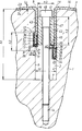
- the drawing shows a schematic radial section the device according to the invention.
- a cylinder 1, preferably a rubber cylinder 1, of a rotary printing press has a cylinder pit 2 which extends parallel to its axis of rotation and extends over the cylinder length.
- This cylinder pit 2 is formed as a U-shaped groove extending radially in the direction of the axis of rotation of the cylinder 1 from a lateral surface 3 of the cylinder 1.
- the cylinder pit 2 of width b1 and height h1 is delimited by two parallel, approximately radially running side surfaces 4, 6 of height h1 and a base surface 7 of width b1 lying perpendicular to these side surfaces 4, 6.
- This groove 9 has two side faces 11, 12 of the width b2 parallel to the base 7 of the cylinder pit 2 and a base 13 of the height h2 parallel to the side faces 4, 6 of the cylinder pit 2.
- a plurality of blind hole-like threaded bores 14 are radially introduced into the base area 7 of the cylinder pit 2 at uniform intervals along the cylinder length.
- An elevator 16 in particular a rubber blanket 16 of thickness d1
- the two ends 17, 18 are each reinforced or framed, for example by means of the mounting rails 21, 22 surrounding the respective end 17, 18 on three sides.
- These mounting rails 21, 22 extend along the cylinder pit 2 and can be U-shaped from metal or dimensionally stable Be made of plastic.
- the hanging rails 21, 22 can each have side legs 31, 32, 33, 34 of different lengths.
- the side leg 32 facing the side surface 6 of the cylinder pit 2 is shorter by at least the thickness d1 of the rubber blanket 2 than the opposite side leg 31 of the hanging rail 21.
- the side leg 33 facing the side surface 4 of the cylinder pit 2 is shorter at least by the thickness d1 of the rubber blanket 16 shorter than the opposite side leg 34 of the hanging rail 22.
- One over the cylinder length, parallel to the axis of rotation of the cylinder 1 extending clamping bar 41 has z. B. a rectangular cross section of width b3 and height h3 on. This width b3 corresponds approximately to the width b1 of the cylinder pit 2 minus twice the thickness d1 of the blanket 16.
- the rectangular cross section the clamping bar 41 is from two to the side surfaces 4, 6 of the cylinder pit 2 parallel side surfaces 42, 43 and one each to the base area 7 the cylinder pit 2 parallel upper and lower Base 44, 46 formed.
- In this tension bar 41 are corresponding to the threaded holes 14 of the Base 7 of the cylinder pit 2 through holes 47 provided. With the threaded holes 14 of Base 7 of the cylinder pit 2 act through the Through holes 47 of the clamping bar 41 protruding Tensioning screws 48 together.
- the tensioning strip 41 including the tensioning screws 48 is removed from the cylinder pit 2.
- the rubber blanket 16 is placed on the outer surface 3 of the cylinder 1 and the ends 17, 18 of the rubber blanket 16 are folded into the cylinder pit 2 so as to lie against the corresponding side surfaces 4, 6.
- the clamping bar 41 is inserted into the cylinder pit 2 with the associated clamping screws 48.
- the clamping screws 48 are screwed into the threaded bores 14 of the base 7 of the cylinder pit 2, as a result of which the clamping bar 41 is moved radially inward in the direction of the axis of rotation of the cylinder 1.
- the lower base surface 46 of the clamping bar 41 presses against the respective pressure surfaces 36, 39 of the side legs 31, 34 of the hanging rails 21, 22.
Landscapes
- Supply, Installation And Extraction Of Printed Sheets Or Plates (AREA)
Description
Vorteilhaft ist zudem die unterschiedliche Länge von Seitenschenkeln der Einhängeleisten, da auch bei einem bei gespannten Aufzug auftretenden Versatz der Einhängeleisten zum Aufzug eine Beschädigung vermieden wird.
Außerdem zeichnet sich die Spannleiste durch als besonders einfach und kostengünstig herzustellendes Bauteil aus.
Ein Aufzug 16, insbesondere ein Gummituch 16 der Dicke d1 weist ein vorderes, am Druckanfang 8 gelegenes Ende 17 und ein hinteres, am Druckende 19 gelegenes Ende 18 auf. Die beiden Enden 17, 18 sind jeweils verstärkt bzw. eingefaßt, beispielsweise mittels das jeweilige Ende 17, 18 an drei Seiten umschließende Einhängeschienen 21, 22. Diese Einhängeschienen 21, 22 erstrecken sich entlang der Zylindergrube 2 und können U-förmig aus Metall oder formstabilen Kunststoff ausgeführt sein.
Am Druckanfang 8 und Druckende 19 können die Einhängeschienen 21, 22 jeweils unterschiedlich lange Seitenschenkel 31, 32, 33, 34 aufweisen. So ist im ausgeführten Beispiel am Druckanfang 8 der der Seitenfläche 6 der Zylindergrube 2 zugewandte Seitenschenkel 32 mindestens um die Dicke d1 des Gummituches 2 kürzer als der gegenüberliegende Seitenschenkel 31 der Einhängeschiene 21. Am Druckende 19 ist der der Seitenfläche 4 der Zylindergrube 2 zugewandte Seitenschenkel 33 mindestens um die Dicke d1 des Gummituches 16 kürzer als der gegenüberliegende Seitenschenkel 34 der Einhängeschiene 22. Durch diese Ausbildung der Einhängeschienen 21, 22 wird während des Spannvorganges eine Beschädigung des Gummituchs 16 durch die Einhängeschiene 21, 22 vermieden.
Zum Entfernen des Gummituches 16 werden die Spannschrauben 48 und die Spannleiste 41 entfernt, worauf das Gummituch 16 entnommen werden kann. Bei Linkslauf des Zylinders 1 ist die gesamte Anordnung der Vorrichtung spiegelbildlich angeordnet.
- 1
- Zylinder (Gummizylinder)
- 2
- Zylindergrube
- 3
- Mantelfläche (1)
- 4
- Seitenfläche (2)
- 5
- -
- 6
- Seitenfläche (2)
- 7
- Grundfläche (2)
- 8
- Druckanfang
- 9
- Nut, U-förmig (6)
- 10
- -
- 11
- Seitenfläche (9)
- 12
- Seitenfläche (9)
- 13
- Grundfläche (9)
- 14
- Gewindebohrung
- 15
- -
- 16
- Aufzug (Gummituch)
- 17
- Ende, vorderes (16)
- 18
- Ende, hinteres (16)
- 19
- Druckende
- 20
- -
- 21
- Einhängeschiene (17)
- 22
- Einhängeschiene (18)
- 23
- Oberseite (16)
- 24
- Unterseite (16)
- 25
- -
- 26
- Seitenfläche (31)
- 27
- Seitenfläche (32)
- 28
- Seitenfläche (33)
- 29
- Seitenfläche (34)
- 30
- -
- 31
- Seitenschenkel (21)
- 32
- Seitenschenkel (21)
- 33
- Seitenschenkel (22)
- 34
- Seitenschenkel (22)
- 35
- -
- 36
- Druckfläche (31)
- 37
- Druckfläche (32)
- 38
- Druckfläche (33)
- 39
- Druckfläche (34)
- 40
- -
- 41
- Spannleiste
- 42
- Seitenfläche (41)
- 43
- Seitenfläche (41)
- 44
- Grundfläche, obere (41)
- 45
- -
- 46
- Grundfläche, untere (41)
- 47
- Durchgangsbohrung (41)
- 48
- Spannschrauben
- b1
- Breite der Zylindergrube (2)
- b2
- Breite der Seitenflächen (11; 12)
- b3
- Breite der Spannleiste (41)
- d1
- Dicke des Aufzuges (16)
- d2
- Dicke der Seitenschenkel (31; 32; 33; 34)
- h1
- Höhe der Zylindergrube (2)
- h2
- Höhe der Grundfläche (13)
- h3
- Höhe der Spannleiste (41)
Claims (7)
- Verfahren zum Befestigen und Spannen eines Aufzugs (16) auf einem mit einer U-förmigen Zylindergrube (2) versehenen Zylinder (1), wobei beide mit Einhängeschienen (21; 22) versehenen Enden (17; 18) des Aufzugs (16) in die Zylindergrube (2) eingelegt werden, dann eine Spannleiste (41) auf die Einhängeschienen (21; 22) beider Enden (17; 18) drückend in die Zylindergrube (2) geführt wird und die Spannleiste (41) radial nach innen, beide Enden (17; 18) spannend bewegt wird, dadurch gekennzeichnet, daß die Spannleiste (41) solange nach innen bewegt wird, bis die Einhängeschiene (21) am Druckanfang (8) in eine in eine Seitenfläche (6) der Zylindergrube (2) befindliche Nut (9) rutscht, daß anschließend die Spannleiste (41) weiter an der in der Nut (9) ortsfest verbleibende Einhängeschiene (21) vorbei, das Ende (18) am Druckende (19) spannend bewegt wird.
- Vorrichtung zum Befestigen und Spannen eines Aufzugs (16) einer Dicke (d1) auf einem Zylinder (1) einer Rotationsdruckmaschine, wobei eine Mantelfläche (3) des Zylinders (1) mit einer von zwei Seitenflächen (4; 6) und einer Grundfläche (7) begrenzten, sich parallel zur Drehachse des Zylinders (1) erstreckenden U-förmigen Zylindergrube (2) versehen ist und eine Breite (b1) der Zylindergrube (2) zumindest in deren oberen Teil unwesentlich größer ist, als eine Summe der doppelten Dicke (d1) des Aufzugs (16) und einer Breite (b3) einer Spannleiste (41) und an jeweiligen Enden (17; 18) des Aufzugs (16) Einhängeschienen (21; 22) mit Seitenschenkeln (31; 32; 33; 34) vorgesehen sind, wobei im gespannten Zustand eine Druckfläche (39) der Einhängeschiene (21) am Druckende (19) mit einer Grundfläche der Spannleiste (41) zusammenwirkend angeordnet ist, dadurch gekennzeichnet, daß die an Druckanfang (8) befindliche Seitenfläche (6) der Zylindergrube (2) eine Nut (9) mit zwei parallel zur Grundfläche (7) der Zylindergrube (2) liegenden Seitenflächen (11; 12) und einer parallel zu den Seitenflächen (4; 6) der Zylindergrube (2) liegende Grundfläche (7) aufweist, daß die Einhängeschienen (21; 22) jeweils zwei über der Ober- bzw. Unterseite (23; 24) des Gummituches liegende Seitenschenkel (31; 32; 33; 34) mit jeweils einer Druckfläche (36; 37; 38; 39) aufweisen, daß die Druckfläche (37) der Einhängeschiene (21) am Druckanfang (8) im gespannten Zustand des Aufzuges (16) mit der oberen Seitenfläche (12) der Nut (9) der Seitenfläche (6) der Zylindergrube (2) zusammenwirkend angeordnet ist.
- Vorrichtung nach Anspruch 2, dadurch gekennzeichnet, daß der rechte Seitenschenkel (31; 33) und der linke Seitenschenkel (32; 34) der jeweiligen Einhängeleiste (21; 22) unterschiedliche Längen aufweisen.
- Vorrichtung nach Anspruch 3, dadurch gekennzeichnet, daß der der Seitenflächen (6) der Zylindergrube (2) am Druckanfang (8) zugewandte Seitenschenkel (32) der Einhängeleiste (21) mindestens um eine Dicke (d1) des Aufzuges (16) länger ist als der gegenüberliegende Seitenschenkel (31) der Einhängeleiste (21) am Druckanfang (8).
- Vorrichtung nach Anspruch 3, dadurch gekennzeichnet, daß der der Seitenfläche (4) der Zylindergrube (2) am Druckende (19) zugewandte Seitenschenkel (33) der Einhängeleiste (22) mindestens um die Dicke (d1) des Aufzuges (16) kürzer ist als der gegenüberliegende Seitenschenkel (34) der Einhängeleiste (22) am Druckende (19).
- Vorrichtung nach den Ansprüchen 1 und 2, dadurch gekennzeichnet, daß die Dicke (d2) der Seitenschenkel (31; 32; 33; 34) kleiner ist als die Dicke (d1) des Aufzuges (16).
- Vorrichtung nach Anspruch 2, dadurch gekennzeichnet, daß die Spannleiste (41) quaderförmig, ohne Aussparungen, mit rechteckigen Querschnitt ausgebildet ist, und daß deren Breite (b3) annähernd der Breite (b1) der Zylindergrube (2) abzüglich der doppelten Dicke (d1) des Aufzuges (16) entspricht.
Applications Claiming Priority (3)
| Application Number | Priority Date | Filing Date | Title |
|---|---|---|---|
| DE4425189A DE4425189C1 (de) | 1994-07-16 | 1994-07-16 | Verfahren und Vorrichtung zum Befestigen und Spannen eines Aufzuges auf einem Zylinder einer Rotationsdruckmaschine |
| DE4425189 | 1994-07-16 | ||
| PCT/DE1995/000913 WO1996002391A1 (de) | 1994-07-16 | 1995-07-13 | Verfahren und vorrichtung zum befestigen und spannen eines aufzuges auf einem zylinder einer rotationsdruckmaschine |
Publications (2)
| Publication Number | Publication Date |
|---|---|
| EP0771270A1 EP0771270A1 (de) | 1997-05-07 |
| EP0771270B1 true EP0771270B1 (de) | 1998-04-15 |
Family
ID=6523353
Family Applications (1)
| Application Number | Title | Priority Date | Filing Date |
|---|---|---|---|
| EP95925684A Expired - Lifetime EP0771270B1 (de) | 1994-07-16 | 1995-07-13 | Verfahren und vorrichtung zum befestigen und spannen eines aufzuges auf einem zylinder einer rotationsdruckmaschine |
Country Status (5)
| Country | Link |
|---|---|
| US (1) | US5809889A (de) |
| EP (1) | EP0771270B1 (de) |
| JP (1) | JP2846123B2 (de) |
| DE (2) | DE4425189C1 (de) |
| WO (1) | WO1996002391A1 (de) |
Families Citing this family (6)
| Publication number | Priority date | Publication date | Assignee | Title |
|---|---|---|---|---|
| DE19616337C2 (de) * | 1996-04-24 | 1999-04-15 | Roland Man Druckmasch | Verfahren und Vorrichtung zum Befestigen und Spannen eines Drucktuches |
| DE19741092C2 (de) * | 1997-09-18 | 2001-02-01 | Koenig & Bauer Ag | Spanneinrichtung |
| DE19860477C2 (de) * | 1998-12-28 | 2001-02-01 | Koenig & Bauer Ag | Gummituch und Vorrichtung zum Befestigen und Spannen dieses Gummituches |
| DE10220548B4 (de) * | 2002-05-08 | 2004-05-27 | Koenig & Bauer Ag | Befestigung eines biegsamen Aufzugs auf einem Zylinder einer Rotationsdruckmaschine |
| DE10224375A1 (de) * | 2002-06-01 | 2003-12-11 | Koenig & Bauer Ag | Gummituch |
| JP7459571B2 (ja) * | 2020-03-05 | 2024-04-02 | 富士フイルムビジネスイノベーション株式会社 | 胴部材及び画像形成装置 |
Family Cites Families (16)
| Publication number | Priority date | Publication date | Assignee | Title |
|---|---|---|---|---|
| DE407871C (de) * | 1922-02-24 | 1925-01-03 | A W Penrose & Co Ltd | Verfahren zum Befestigen eines Druckbleches auf einem Formzylinder und Formzylinder zur Ausfuehrung des Verfahrens |
| US1582390A (en) * | 1923-01-18 | 1926-04-27 | Evans Arthur Burroughes | Printing machine |
| DE431764C (de) * | 1924-06-26 | 1926-07-17 | A W Penrose & Company Ltd | Vorrichtung zum Befestigen biegsamer Tiefdruckplatten bei Rotationsdruckmaschinen |
| US2729164A (en) * | 1948-06-17 | 1956-01-03 | Laszlo M Stempel | Transfer printing mechanism |
| US2885958A (en) * | 1954-10-25 | 1959-05-12 | Harris Intertype Corp | Printing plate mounting means |
| US3296673A (en) * | 1964-05-04 | 1967-01-10 | Alven D Kirkpatrick | Printing blanket edging and anchoring means |
| US3495531A (en) * | 1966-01-17 | 1970-02-17 | Chandler & Price Co | Web press with fountain roller and ductor roller drive |
| GB1269539A (en) * | 1968-09-26 | 1972-04-06 | Dayco Corp | Apparatus for mounting a printing blanket on a printing press cylinder |
| US3584580A (en) * | 1969-08-25 | 1971-06-15 | Leipzig Veb Druckmasch Werke | Rubber sheet tensioning device for offset printing machines |
| US4337700A (en) * | 1980-05-30 | 1982-07-06 | Pathfinder Graphic Associates, Inc. | Blanket cylinder construction for printing press |
| DE3109859C2 (de) * | 1981-03-14 | 1983-05-11 | Albert-Frankenthal Ag, 6710 Frankenthal | Gummituchspannvorrichtung |
| FR2527983B1 (fr) * | 1982-06-04 | 1986-06-06 | Creusot Loire | Dispositif de fixation de l'habillage d'un cylindre de machine d'impression |
| US4833986A (en) * | 1987-03-05 | 1989-05-30 | M.A.N. Roland Druckmaschinen Ag | Holding and tensioning system for a cover layer on a printing machine cylinder |
| DE3707066A1 (de) * | 1987-03-05 | 1988-09-15 | Roland Man Druckmasch | Spannvorrichtung zur befestigung eines aufzuges am zylinder einer rotationsdruckmaschine |
| JPH0413740A (ja) * | 1990-05-08 | 1992-01-17 | Asahi Fiber Glass Co Ltd | 熱可塑性樹脂用混入材並びに樹脂成形体 |
| DE4210778C2 (de) * | 1992-04-01 | 1994-03-31 | Roland Man Druckmasch | Sicherungsvorrichtung für Spannschienen zum Spannen von Gummitüchern |
-
1994
- 1994-07-16 DE DE4425189A patent/DE4425189C1/de not_active Expired - Fee Related
-
1995
- 1995-07-13 US US08/765,441 patent/US5809889A/en not_active Expired - Fee Related
- 1995-07-13 DE DE59501928T patent/DE59501928D1/de not_active Expired - Fee Related
- 1995-07-13 WO PCT/DE1995/000913 patent/WO1996002391A1/de not_active Ceased
- 1995-07-13 JP JP7527200A patent/JP2846123B2/ja not_active Expired - Fee Related
- 1995-07-13 EP EP95925684A patent/EP0771270B1/de not_active Expired - Lifetime
Also Published As
| Publication number | Publication date |
|---|---|
| WO1996002391A1 (de) | 1996-02-01 |
| DE59501928D1 (de) | 1998-05-20 |
| US5809889A (en) | 1998-09-22 |
| EP0771270A1 (de) | 1997-05-07 |
| DE4425189C1 (de) | 1996-02-01 |
| JPH09507659A (ja) | 1997-08-05 |
| JP2846123B2 (ja) | 1999-01-13 |
Similar Documents
| Publication | Publication Date | Title |
|---|---|---|
| DE2654255A1 (de) | Spannvorrichtung fuer druckplatten | |
| EP0771270B1 (de) | Verfahren und vorrichtung zum befestigen und spannen eines aufzuges auf einem zylinder einer rotationsdruckmaschine | |
| DE10049348A1 (de) | Linearführungsanordnung | |
| DE1228627B (de) | Vorrichtung zum Befestigen einer biegsamen Druckplatte auf dem Formzylinder einer Rotationsdruckmaschine | |
| EP0553462A1 (de) | Supportverbindungen zwischen zwei Walzen | |
| DE102004028448B4 (de) | Schutzvorrichtung zum Halten einer Druckschablone und Schablonenspannrahmen | |
| DE1997948U (de) | Loesbare nutfederverbindung zur halterung streifen- und plattenfoermiger bauteile | |
| EP0755785B1 (de) | Plattenklemmeinrichtung zur Reduzierung des druckfreien Bereiches | |
| DE3007975B1 (de) | Pressenrahmen,bei dem Oberholm,Unterholm und Staender durch Spannelemente zusammengespannt sind | |
| DE3109859C2 (de) | Gummituchspannvorrichtung | |
| CH688191A5 (de) | Spindel. | |
| CH687070A5 (de) | Gummituchspannung. | |
| DE69201423T2 (de) | Lösbare flexible Webschaftrahmeneckverbindung für Webmaschinen. | |
| DE4341426C2 (de) | Vorrichtung zur Befestigung von Formen an Zylindern von Veredelungseinheiten | |
| EP0479266B1 (de) | Stützeinrichtung in einer Zylindergrube | |
| DE19741092C2 (de) | Spanneinrichtung | |
| DE4011303A1 (de) | Vorrichtung zum befestigen eines gummituches auf einem gummizylinder einer offsetdruckmaschine | |
| DE533694C (de) | Vorrichtung zum Aufspannen von biegsamen Druckplatten auf dem Formzylinder von Tiefdruckmaschinen | |
| DE3809667C1 (en) | Device for attaching the rubber blanket on the blanket cylinder | |
| DE2064712C2 (de) | Sieb-Spannvorrichtung eines Siebdruckrahmens | |
| DE3425993C1 (de) | Werkstückaufspannplatte | |
| DE19834068C1 (de) | Wiederverwendbare, flexographische Druckform zum Aufbringen von Farb- oder Leimmustern mit Spannvorrichtung für die Trägerschicht | |
| EP1140501A1 (de) | Gummituch und vorrichtung zum befestigen eines gummituches | |
| DE2902361C2 (de) | Hydraulische Schraubenspannvorrichtung | |
| EP1561954A1 (de) | Verbindungselement zum lösbaren Verbinden von sich teilweise überlappenden Teilen sowie ein derartige Verbindungselemente aufweisendes Gehäuse und ein Verfahren zum lösbaren Verbinden von sich wenigstens teilweise überlappenden Teilen |
Legal Events
| Date | Code | Title | Description |
|---|---|---|---|
| PUAI | Public reference made under article 153(3) epc to a published international application that has entered the european phase |
Free format text: ORIGINAL CODE: 0009012 |
|
| 17P | Request for examination filed |
Effective date: 19961219 |
|
| AK | Designated contracting states |
Kind code of ref document: A1 Designated state(s): CH DE FR GB IT LI SE |
|
| GRAG | Despatch of communication of intention to grant |
Free format text: ORIGINAL CODE: EPIDOS AGRA |
|
| GRAG | Despatch of communication of intention to grant |
Free format text: ORIGINAL CODE: EPIDOS AGRA |
|
| GRAH | Despatch of communication of intention to grant a patent |
Free format text: ORIGINAL CODE: EPIDOS IGRA |
|
| 17Q | First examination report despatched |
Effective date: 19970923 |
|
| ITF | It: translation for a ep patent filed | ||
| GRAH | Despatch of communication of intention to grant a patent |
Free format text: ORIGINAL CODE: EPIDOS IGRA |
|
| GRAA | (expected) grant |
Free format text: ORIGINAL CODE: 0009210 |
|
| AK | Designated contracting states |
Kind code of ref document: B1 Designated state(s): CH DE FR GB IT LI SE |
|
| REG | Reference to a national code |
Ref country code: CH Ref legal event code: EP |
|
| GBT | Gb: translation of ep patent filed (gb section 77(6)(a)/1977) |
Effective date: 19980415 |
|
| REF | Corresponds to: |
Ref document number: 59501928 Country of ref document: DE Date of ref document: 19980520 |
|
| ET | Fr: translation filed | ||
| RAP2 | Party data changed (patent owner data changed or rights of a patent transferred) |
Owner name: KOENIG & BAUER AKTIENGESELLSCHAFT |
|
| PLBE | No opposition filed within time limit |
Free format text: ORIGINAL CODE: 0009261 |
|
| STAA | Information on the status of an ep patent application or granted ep patent |
Free format text: STATUS: NO OPPOSITION FILED WITHIN TIME LIMIT |
|
| 26N | No opposition filed | ||
| REG | Reference to a national code |
Ref country code: GB Ref legal event code: IF02 |
|
| PGFP | Annual fee paid to national office [announced via postgrant information from national office to epo] |
Ref country code: GB Payment date: 20040628 Year of fee payment: 10 |
|
| PGFP | Annual fee paid to national office [announced via postgrant information from national office to epo] |
Ref country code: FR Payment date: 20040721 Year of fee payment: 10 |
|
| PGFP | Annual fee paid to national office [announced via postgrant information from national office to epo] |
Ref country code: SE Payment date: 20040726 Year of fee payment: 10 |
|
| PGFP | Annual fee paid to national office [announced via postgrant information from national office to epo] |
Ref country code: CH Payment date: 20040802 Year of fee payment: 10 |
|
| PGFP | Annual fee paid to national office [announced via postgrant information from national office to epo] |
Ref country code: DE Payment date: 20040927 Year of fee payment: 10 |
|
| PG25 | Lapsed in a contracting state [announced via postgrant information from national office to epo] |
Ref country code: IT Free format text: LAPSE BECAUSE OF NON-PAYMENT OF DUE FEES Effective date: 20050713 Ref country code: GB Free format text: LAPSE BECAUSE OF NON-PAYMENT OF DUE FEES Effective date: 20050713 |
|
| PG25 | Lapsed in a contracting state [announced via postgrant information from national office to epo] |
Ref country code: SE Free format text: LAPSE BECAUSE OF NON-PAYMENT OF DUE FEES Effective date: 20050714 |
|
| PG25 | Lapsed in a contracting state [announced via postgrant information from national office to epo] |
Ref country code: LI Free format text: LAPSE BECAUSE OF NON-PAYMENT OF DUE FEES Effective date: 20050731 Ref country code: CH Free format text: LAPSE BECAUSE OF NON-PAYMENT OF DUE FEES Effective date: 20050731 |
|
| PG25 | Lapsed in a contracting state [announced via postgrant information from national office to epo] |
Ref country code: DE Free format text: LAPSE BECAUSE OF NON-PAYMENT OF DUE FEES Effective date: 20060201 |
|
| REG | Reference to a national code |
Ref country code: CH Ref legal event code: PL |
|
| EUG | Se: european patent has lapsed | ||
| GBPC | Gb: european patent ceased through non-payment of renewal fee |
Effective date: 20050713 |
|
| PG25 | Lapsed in a contracting state [announced via postgrant information from national office to epo] |
Ref country code: FR Free format text: LAPSE BECAUSE OF NON-PAYMENT OF DUE FEES Effective date: 20060331 |
|
| REG | Reference to a national code |
Ref country code: FR Ref legal event code: ST Effective date: 20060331 |