EP0771270B1 - Process and device for securing and tightening a packing on the cylinder of a rotary printing machine - Google Patents
Process and device for securing and tightening a packing on the cylinder of a rotary printing machine Download PDFInfo
- Publication number
- EP0771270B1 EP0771270B1 EP95925684A EP95925684A EP0771270B1 EP 0771270 B1 EP0771270 B1 EP 0771270B1 EP 95925684 A EP95925684 A EP 95925684A EP 95925684 A EP95925684 A EP 95925684A EP 0771270 B1 EP0771270 B1 EP 0771270B1
- Authority
- EP
- European Patent Office
- Prior art keywords
- cylinder
- hang
- tensioning
- strip
- covering
- Prior art date
- Legal status (The legal status is an assumption and is not a legal conclusion. Google has not performed a legal analysis and makes no representation as to the accuracy of the status listed.)
- Expired - Lifetime
Links
- 238000000034 method Methods 0.000 title claims description 11
- 238000012856 packing Methods 0.000 title 1
- 102000001999 Transcription Factor Pit-1 Human genes 0.000 description 19
- 108010040742 Transcription Factor Pit-1 Proteins 0.000 description 19
- 210000002414 leg Anatomy 0.000 description 17
- 239000000725 suspension Substances 0.000 description 8
- 239000000853 adhesive Substances 0.000 description 1
- 230000001070 adhesive effect Effects 0.000 description 1
- 239000002184 metal Substances 0.000 description 1
- 239000004033 plastic Substances 0.000 description 1
- 210000000689 upper leg Anatomy 0.000 description 1
- 238000004073 vulcanization Methods 0.000 description 1
Images
Classifications
-
- B—PERFORMING OPERATIONS; TRANSPORTING
- B41—PRINTING; LINING MACHINES; TYPEWRITERS; STAMPS
- B41F—PRINTING MACHINES OR PRESSES
- B41F30/00—Devices for attaching coverings or make-ready devices; Guiding devices for coverings
- B41F30/04—Devices for attaching coverings or make-ready devices; Guiding devices for coverings attaching to transfer cylinders
-
- B—PERFORMING OPERATIONS; TRANSPORTING
- B41—PRINTING; LINING MACHINES; TYPEWRITERS; STAMPS
- B41F—PRINTING MACHINES OR PRESSES
- B41F27/00—Devices for attaching printing elements or formes to supports
- B41F27/12—Devices for attaching printing elements or formes to supports for attaching flexible printing formes
- B41F27/1218—Devices for attaching printing elements or formes to supports for attaching flexible printing formes comprising printing plate tensioning devices
- B41F27/1225—Devices for attaching printing elements or formes to supports for attaching flexible printing formes comprising printing plate tensioning devices moving in the printing plate end substantially rectilinearly
- B41F27/1237—Devices for attaching printing elements or formes to supports for attaching flexible printing formes comprising printing plate tensioning devices moving in the printing plate end substantially rectilinearly by translatory motion substantially perpendicular to support surface
Definitions
- the invention relates to a method and Device for fastening and tensioning an elevator on a cylinder of a rotary printing press.
- EP 00 99 275 B1 is a generic one Device for fastening and tensioning an elevator known.
- a cylinder of a printing press longitudinal and radial incision as a cylinder pit educated.
- this cylinder pit can be Clamping screws are moved radially around a clamping bar.
- This clamping bar is offset from one another Provide shoulders for print start and print end. With these shoulders, edges of Hanging rails at the respective ends of the Elevator are attached, held.
- DE 37 07 066 C2 shows a tensioning device positive locking of an elevator to the cylinder a rotary printing press.
- the cylinder has one axially parallel pit running in the cylinder jacket one that can be moved radially inward during the clamping process Tension bar on.
- This tension bar is on its upper part with a recess on each side for receiving provided by reinforced ends of the elevator.
- a disadvantage of these known devices is that due to occurring walking processes during the first time Printing after the lift is put on unilateral loosening of the elevator is not compensated can be. Only two can be used in these devices Ends are stretched evenly, but by a large one Stiction of the elevator on the cylinder is a Balance between the two ends is not possible. Consequently either the loose end does not meet the requirements be tensioned accordingly or the fixed end will overstretched, d. H. destroyed. A removal or Tear out the reinforced ends.
- the invention has for its object a method and a spindle-free device for fastening and Tensioning an elevator on a cylinder one To create rotary printing press, with or with the a due to flexing that occurs during printing arising unilateral loosening of the elevator on End of printing can be eliminated.
- this object is achieved by a method or a device for fastening and tensioning a Elevator on a cylinder of a rotary printing press with the characteristics of the characteristic part of the Claim 1 or claim 2 solved.
- An elevator of a cylinder can advantageously be retensioned at the end of the print.
- the tensioned and tensioned lifts of a cylinder of a rotary printing press are loosened by flexing processes that occur during printing. These flexing processes begin at the beginning of the print and roll the elevator towards the end of the print, which loosens the end of the lift located at the print end.
- flexing processes begin at the beginning of the print and roll the elevator towards the end of the print, which loosens the end of the lift located at the print end.
- a single re-tensioning is usually sufficient, but it can also be re-tensioned several times.
- the different length of the side legs of the suspension rails is also advantageous, since damage is avoided even when the suspension rails are offset from the elevator when the elevator is under tension.
- the tensioning strip is characterized by a particularly simple and inexpensive component to be produced.
- the device according to the invention is in the drawing shown and is described in more detail below.
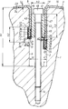
- the drawing shows a schematic radial section the device according to the invention.
- a cylinder 1, preferably a rubber cylinder 1, of a rotary printing press has a cylinder pit 2 which extends parallel to its axis of rotation and extends over the cylinder length.
- This cylinder pit 2 is formed as a U-shaped groove extending radially in the direction of the axis of rotation of the cylinder 1 from a lateral surface 3 of the cylinder 1.
- the cylinder pit 2 of width b1 and height h1 is delimited by two parallel, approximately radially running side surfaces 4, 6 of height h1 and a base surface 7 of width b1 lying perpendicular to these side surfaces 4, 6.
- This groove 9 has two side faces 11, 12 of the width b2 parallel to the base 7 of the cylinder pit 2 and a base 13 of the height h2 parallel to the side faces 4, 6 of the cylinder pit 2.
- a plurality of blind hole-like threaded bores 14 are radially introduced into the base area 7 of the cylinder pit 2 at uniform intervals along the cylinder length.
- An elevator 16 in particular a rubber blanket 16 of thickness d1
- the two ends 17, 18 are each reinforced or framed, for example by means of the mounting rails 21, 22 surrounding the respective end 17, 18 on three sides.
- These mounting rails 21, 22 extend along the cylinder pit 2 and can be U-shaped from metal or dimensionally stable Be made of plastic.
- the hanging rails 21, 22 can each have side legs 31, 32, 33, 34 of different lengths.
- the side leg 32 facing the side surface 6 of the cylinder pit 2 is shorter by at least the thickness d1 of the rubber blanket 2 than the opposite side leg 31 of the hanging rail 21.
- the side leg 33 facing the side surface 4 of the cylinder pit 2 is shorter at least by the thickness d1 of the rubber blanket 16 shorter than the opposite side leg 34 of the hanging rail 22.
- One over the cylinder length, parallel to the axis of rotation of the cylinder 1 extending clamping bar 41 has z. B. a rectangular cross section of width b3 and height h3 on. This width b3 corresponds approximately to the width b1 of the cylinder pit 2 minus twice the thickness d1 of the blanket 16.
- the rectangular cross section the clamping bar 41 is from two to the side surfaces 4, 6 of the cylinder pit 2 parallel side surfaces 42, 43 and one each to the base area 7 the cylinder pit 2 parallel upper and lower Base 44, 46 formed.
- In this tension bar 41 are corresponding to the threaded holes 14 of the Base 7 of the cylinder pit 2 through holes 47 provided. With the threaded holes 14 of Base 7 of the cylinder pit 2 act through the Through holes 47 of the clamping bar 41 protruding Tensioning screws 48 together.
- the tensioning strip 41 including the tensioning screws 48 is removed from the cylinder pit 2.
- the rubber blanket 16 is placed on the outer surface 3 of the cylinder 1 and the ends 17, 18 of the rubber blanket 16 are folded into the cylinder pit 2 so as to lie against the corresponding side surfaces 4, 6.
- the clamping bar 41 is inserted into the cylinder pit 2 with the associated clamping screws 48.
- the clamping screws 48 are screwed into the threaded bores 14 of the base 7 of the cylinder pit 2, as a result of which the clamping bar 41 is moved radially inward in the direction of the axis of rotation of the cylinder 1.
- the lower base surface 46 of the clamping bar 41 presses against the respective pressure surfaces 36, 39 of the side legs 31, 34 of the hanging rails 21, 22.
Landscapes
- Supply, Installation And Extraction Of Printed Sheets Or Plates (AREA)
Description
Die Erfindung betrifft ein Verfahren und eine Vorrichtung zum Befestigen und Spannen eines Aufzuges auf einem Zylinder einer Rotationsdruckmaschine.The invention relates to a method and Device for fastening and tensioning an elevator on a cylinder of a rotary printing press.
Aus der EP 00 99 275 B1 ist eine gattungsgemäße Vorrichtung zum Befestigen und Spannen eines Aufzuges bekannt. In einem Zylinder einer Druckmaschine ist ein longitudinaler und radialer Einschnitt als Zylindergrube ausgebildet. In dieser Zylindergrube kann mittels Spannschrauben eine Spannleiste radial bewegt werden. Diese Spannleiste ist mit zueinander versetzten Schultern für Druckanfang und Druckende versehen. Mittels dieser Schultern werden Ränder von Einhängeleisten, die an den jeweiligen Enden des Aufzuges befestigt sind, festgehalten.EP 00 99 275 B1 is a generic one Device for fastening and tensioning an elevator known. There is a in a cylinder of a printing press longitudinal and radial incision as a cylinder pit educated. In this cylinder pit can be Clamping screws are moved radially around a clamping bar. This clamping bar is offset from one another Provide shoulders for print start and print end. With these shoulders, edges of Hanging rails at the respective ends of the Elevator are attached, held.
Die DE 37 07 066 C2 zeigt eine Spannvorrichtung zur formschlüssigen Befestigung eines Aufzugs am Zylinder einer Rotationsdruckmaschine. Der Zylinder weist eine achsparallele im Zylindermantel verlaufende Grube mit einer beim Spannvorgang radial nach innen bewegbaren Spannleiste auf. Diese Spannleiste ist an ihrem Oberteil auf beiden Seiten mit je einer Aussparung zur Aufnahme von verstärkten Enden des Aufzuges versehen. DE 37 07 066 C2 shows a tensioning device positive locking of an elevator to the cylinder a rotary printing press. The cylinder has one axially parallel pit running in the cylinder jacket one that can be moved radially inward during the clamping process Tension bar on. This tension bar is on its upper part with a recess on each side for receiving provided by reinforced ends of the elevator.
Nachteilig an diesen bekannten Vorrichtungen ist, daß durch auftretende Walkvorgänge während des erstmaligen Druckens nach Auflegen des Aufzuges entstehende einseitige Lockerung des Aufzuges nicht ausgeglichen werden kann. Bei diesen Vorrichtungen können nur beide Enden gleichmäßig gespannt werden, aber durch eine große Haftreibung des Aufzuges auf dem Zylinder ist ein Ausgleich zwischen den beiden Enden nicht möglich. Somit kann entweder das lockere Ende nicht den Erfordernissen entsprechend gespannt werden oder das feste Ende wird überdehnt, d. h. zerstört. Auch kann ein Ab- bzw. Ausreißen der verstärkten Enden erfolgen.A disadvantage of these known devices is that due to occurring walking processes during the first time Printing after the lift is put on unilateral loosening of the elevator is not compensated can be. Only two can be used in these devices Ends are stretched evenly, but by a large one Stiction of the elevator on the cylinder is a Balance between the two ends is not possible. Consequently either the loose end does not meet the requirements be tensioned accordingly or the fixed end will overstretched, d. H. destroyed. A removal or Tear out the reinforced ends.
Der Erfindung liegt die Aufgabe zugrunde, ein Verfahren und eine spannspindellose Vorrichtung zum Befestigen und Spannen eines Aufzuges auf einem Zylinder einer Rotationsdruckmaschine zu schaffen, mit dem bzw. mit der eine durch während des Druckens auftretende Walkvorgänge entstehende einseitige Lockerung des Aufzuges am Druckende beseitigt werden kann.The invention has for its object a method and a spindle-free device for fastening and Tensioning an elevator on a cylinder one To create rotary printing press, with or with the a due to flexing that occurs during printing arising unilateral loosening of the elevator on End of printing can be eliminated.
Diese Aufgabe wird erfindungsgemäß durch ein Verfahren bzw. eine Vorrichtung zum Befestigen und Spannen eines Aufzuges auf einem Zylinder einer Rotationsdruckmaschine mit den Merkmalen des kennzeichnenden Teiles des Anspruches 1 oder des Anspruches 2 gelöst.According to the invention, this object is achieved by a method or a device for fastening and tensioning a Elevator on a cylinder of a rotary printing press with the characteristics of the characteristic part of the Claim 1 or claim 2 solved.
In vorteilhafter Weise kann ein Aufzug eines Zylinders
am Druckende nachgespannt werden. Erstmalig
aufgelegte und gespannte Aufzüge eines Zylinders einer
Rotationsdruckmaschine lockern sich durch beim Drucken
auftretende Walkvorgänge. Diese Walkvorgänge beginnen am
Druckanfang und walken den Aufzug in Richtung Druckende
aus, wodurch eine Lockerung des am Druckende gelegenen
Ende des Aufzuges erfolgt. Erfahrungsgemäß muß daher nur
das Druckende besonders nachgespannt werden, da dadurch
eine gleichmäßige Spannung des Aufzuges entsprechend
der Walkvorgängen erfolgt. Meist ist ein einmaliger
Nachspannvorgang ausreichend, es kann aber auch mehrfach
nachgespannt werden.
Vorteilhaft ist zudem die unterschiedliche Länge
von Seitenschenkeln der Einhängeleisten, da auch bei
einem bei gespannten Aufzug auftretenden Versatz der
Einhängeleisten zum Aufzug eine Beschädigung vermieden
wird.
Außerdem zeichnet sich die Spannleiste durch als
besonders einfach und kostengünstig herzustellendes
Bauteil aus.An elevator of a cylinder can advantageously be retensioned at the end of the print. For the first time, the tensioned and tensioned lifts of a cylinder of a rotary printing press are loosened by flexing processes that occur during printing. These flexing processes begin at the beginning of the print and roll the elevator towards the end of the print, which loosens the end of the lift located at the print end. Experience has shown that only the end of the print has to be specially tightened, since this results in a uniform tensioning of the elevator in accordance with the flexing processes. A single re-tensioning is usually sufficient, but it can also be re-tensioned several times.
The different length of the side legs of the suspension rails is also advantageous, since damage is avoided even when the suspension rails are offset from the elevator when the elevator is under tension.
In addition, the tensioning strip is characterized by a particularly simple and inexpensive component to be produced.
Die erfindungsgemäße Vorrichtung ist in der Zeichnung dargestellt und wird im folgenden näher beschrieben.The device according to the invention is in the drawing shown and is described in more detail below.
Die Zeichnung zeigt einen schematischen Radialschnitt der erfindungsgemäßen Vorrichtung.The drawing shows a schematic radial section the device according to the invention.
Ein Zylinder 1, vorzugsweise Gummizylinder 1,
einer Rotationsdruckmaschine weist eine parallel zu
seiner Drehachse verlaufende, über die Zylinderlänge
erstreckende Zylindergrube 2 auf. Diese Zylindergrube
2 ist als von einer Mantelfläche 3 des Zylinders 1
radial in Richtung Drehachse des Zylinders 1 verlaufende
U-förmige Nut ausgebildet. Die Zylindergrube 2 der
Breite b1 und Höhe h1 wird von zwei parallelen,
annähernd radial verlaufenden Seitenflächen 4, 6 der
Höhe h1 und einer senkrecht zu diesen Seitenflächen
4, 6 liegenden Grundfläche 7 der Breite b1 begrenzt.
Die am Druckanfang 8 liegende Seitenfläche 6, d. h.
bei Rechtsdrehung des Zylinders 1 linke Seitenfläche
6, ist mit einer parallel zur Drehachse des Zylinders
1 verlaufenden, über die Länge der Seitenfläche 6
erstreckenden U-förmigen Nut 9 versehen. Diese Nut
9 weist zwei zur Grundfläche 7 der Zylindergrube 2
parallele Seitenflächen 11, 12 der Breite b2 und eine
zu den Seitenflächen 4, 6 der Zylindergrube 2 parallele
Grundfläche 13 der Höhe h2 auf. In die Grundfläche
7 der Zylindergrube 2 sind in gleichmäßigen Abständen
entlang der Zylinderlänge mehrere sacklochartige
Gewindebohrungen 14 radial eingebracht.
Ein Aufzug 16, insbesondere ein Gummituch 16 der Dicke
d1 weist ein vorderes, am Druckanfang 8 gelegenes Ende
17 und ein hinteres, am Druckende 19 gelegenes Ende 18
auf. Die beiden Enden 17, 18 sind jeweils verstärkt bzw.
eingefaßt, beispielsweise mittels das jeweilige Ende
17, 18 an drei Seiten umschließende Einhängeschienen
21, 22. Diese Einhängeschienen 21, 22 erstrecken sich
entlang der Zylindergrube 2 und können U-förmig aus
Metall oder formstabilen Kunststoff ausgeführt sein. A cylinder 1, preferably a rubber cylinder 1, of a rotary printing press has a
An
An Ober- und Unterseite 23, 24 des Gummituches 16
anliegende, innenliegende Seitenflächen 26, 27, 28, 29
von rechten und linken Seitenschenkeln 31, 32, 33, 34
der U-förmigen Einhängschienen 21, 22 können profiliert,
d. h. mit Erhebungen versehen sein, um somit neben
einem durch Zusammenpressen der Einhängeschienen 21,
22 erreichten Reibschluß auch noch einen Formschluß
zu erhalten. Die Einhängeschienen 21, 22 können
aber auch mittels einer Klebeverbindung oder durch
Vulkanisation mit den Enden 17, 18 des Gummituches 16
verbunden sein. Die Seitenschenkel 31, 32, 33, 34 der
Dicke d2 stehen annähernd um diese Dicke d2 über der
Oberfläche des Gummituches und bilden somit jeweils eine
senkrecht zum jeweiligen Seitenschenkel 31, 32, 33, 34
stehende Druckfläche 36, 37, 38, 39. Die Dicke d2 der
Seitenschenkel 31, 32, 33, 34 ist kleiner als die Dicke
d1 des Gummituches 16.
Am Druckanfang 8 und Druckende 19 können die
Einhängeschienen 21, 22 jeweils unterschiedlich
lange Seitenschenkel 31, 32, 33, 34 aufweisen. So
ist im ausgeführten Beispiel am Druckanfang 8 der
der Seitenfläche 6 der Zylindergrube 2 zugewandte
Seitenschenkel 32 mindestens um die Dicke d1 des
Gummituches 2 kürzer als der gegenüberliegende
Seitenschenkel 31 der Einhängeschiene 21. Am Druckende
19 ist der der Seitenfläche 4 der Zylindergrube 2
zugewandte Seitenschenkel 33 mindestens um die Dicke
d1 des Gummituches 16 kürzer als der gegenüberliegende
Seitenschenkel 34 der Einhängeschiene 22. Durch diese
Ausbildung der Einhängeschienen 21, 22 wird während des
Spannvorganges eine Beschädigung des Gummituchs 16 durch
die Einhängeschiene 21, 22 vermieden.On the top and
At the beginning of the print 8 and the end of the
Eine sich über die Zylinderlänge, parallel zur Drehachse
des Zylinders 1 erstreckende Spannleiste 41 weist z. B.
einen rechteckigen Querschnitt der Breite b3 und Höhe
h3 auf. Diese Breite b3 entspricht etwa der Breite
b1 der Zylindergrube 2 abzüglich der doppelten Dicke
d1 des Gummituches 16. Der rechteckige Querschnitt
der Spannleiste 41 wird von zwei zu den Seitenflächen
4, 6 der Zylindergrube 2 parallelen Seitenflächen
42, 43 sowie von je einer zu der Grundfläche 7
der Zylindergrube 2 parallelen oberen und unteren
Grundfläche 44, 46 gebildet. In dieser Spannleiste
41 sind entsprechend den Gewindebohrungen 14 der
Grundfläche 7 der Zylindergrube 2 Durchgangsbohrungen
47 vorgesehen. Mit den Gewindebohrungen 14 der
Grundfläche 7 der Zylindergrube 2 wirken durch die
Durchgangsbohrungen 47 der Spannleiste 41 ragende
Spannschrauben 48 zusammen.One over the cylinder length, parallel to the axis of rotation
of the cylinder 1 extending
Zum Einlegen des Gummituches 16 ist die Spannleiste
41 einschließlich der Spannschrauben 48 aus der
Zylindergrube 2 entfernt. Das Gummituch 16 wird auf
die Mantelfläche 3 des Zylinders 1 aufgelegt und die
Enden 17, 18 des Gummituches 16 in die Zylindergrube
2 an die entsprechenden Seitenflächen 4, 6 anliegend
umgelegt. Die Spannleiste 41 wird mit den dazugehörigen
Spannschrauben 48 in die Zylindergrube 2 eingeführt.
Die Spannschrauben 48 werden in die Gewindebohrungen 14
der Grundfläche 7 der Zylindergrube 2 eingeschraubt,
wodurch die Spannleiste 41 radial nach innen in Richtung
Drehachse des Zylinders 1 bewegt wird. Hierbei drückt
die untere Grundfläche 46 der Spannleiste 41 gegen die
jeweilige Druckflächen 36, 39 der Seitenschenkel 31, 34
der Einhängeschienen 21, 22. Erreicht die Druckfläche
37 des Seitenschenkels 32 am Druckanfang 8 die obere
Seitenfläche 12 der U-förmigen Nut 9 der linken
Seitenfläche 6, kippt die Einhängeschiene 21 durch
den Zugkrafteinflusses des Gummituches 16 und rutscht
seitlich unter der Spannleiste 41 hervor in die Nut 9.
Dort liegt nun die Druckfläche 39 des Seitenschenkels 34
an der oberen Seitenfläche 11 der U-förmigen Nut 9 an.
Beim weiteren Anziehen der Spannschrauben 48 bleibt
die Einhängeschiene 22 am Druckanfang 8 in der Nut 9,
während die Einhängeschiene 21 am Druckende 19 durch die
Spannleiste 41 weitere radial in Richtung Grundfläche
7 der Zylindergrube 2 gezogen wird. Dadurch wird das
Gummituch 16, insbesondere am Druckende 19 gespannt.
Zum Entfernen des Gummituches 16 werden die
Spannschrauben 48 und die Spannleiste 41 entfernt,
worauf das Gummituch 16 entnommen werden kann. Bei
Linkslauf des Zylinders 1 ist die gesamte Anordnung der
Vorrichtung spiegelbildlich angeordnet. To insert the
To remove the
- 11
- Zylinder (Gummizylinder)Cylinder (rubber cylinder)
- 22nd
- ZylindergrubeCylinder pit
- 33rd
- Mantelfläche (1)Lateral surface (1)
- 44th
- Seitenfläche (2)Side (2)
- 55
- --
- 66
- Seitenfläche (2)Side surface (2)
- 77
- Grundfläche (2)Footprint (2)
- 88th
- DruckanfangStart of printing
- 99
- Nut, U-förmig (6)Groove, U-shaped (6)
- 1010th
- --
- 1111
- Seitenfläche (9)Side surface (9)
- 1212th
- Seitenfläche (9)Side (9)
- 1313
- Grundfläche (9)Footprint (9)
- 1414
- GewindebohrungTapped hole
- 1515
- --
- 1616
- Aufzug (Gummituch)Elevator (Rubber blanket)
- 1717th
- Ende, vorderes (16)Front end (16)
- 1818th
- Ende, hinteres (16)Rear end (16)
- 1919th
- DruckendeEnd of printing
- 2020th
- --
- 2121
- Einhängeschiene (17)Hanging rail (17)
- 2222
- Einhängeschiene (18)Suspension rail (18)
- 2323
- Oberseite (16)Top (16)
- 2424th
- Unterseite (16)Underside (16)
- 2525th
- --
- 2626
- Seitenfläche (31)Side surface (31)
- 2727
- Seitenfläche (32) Side (32)
- 2828
- Seitenfläche (33)Side (33)
- 2929
- Seitenfläche (34)Side (34)
- 3030th
- --
- 3131
- Seitenschenkel (21)Side thighs (21)
- 3232
- Seitenschenkel (21)Side legs (21)
- 3333
- Seitenschenkel (22)Side legs (22)
- 3434
- Seitenschenkel (22)Side legs (22)
- 3535
- --
- 3636
- Druckfläche (31)Printing area (31)
- 3737
- Druckfläche (32)Printing area (32)
- 3838
- Druckfläche (33)Printing area (33)
- 3939
- Druckfläche (34)Printing area (34)
- 4040
- --
- 4141
- SpannleisteTensioning bar
- 4242
- Seitenfläche (41)Side (41)
- 4343
- Seitenfläche (41)Side (41)
- 4444
- Grundfläche, obere (41)Base area, upper (41)
- 4545
- --
- 4646
- Grundfläche, untere (41)Floor space, lower (41)
- 4747
- Durchgangsbohrung (41)Through hole (41)
- 4848
- SpannschraubenTurnbuckles
- b1b1
- Breite der Zylindergrube (2)Cylinder pit width (2)
- b2b2
- Breite der Seitenflächen (11; 12)Width of the side surfaces (11; 12)
- b3b3
- Breite der Spannleiste (41)Width of the tensioning bar (41)
- d1d1
- Dicke des Aufzuges (16)Lift thickness (16)
- d2d2
- Dicke der Seitenschenkel (31; 32; 33; 34) Thickness of the side legs (31; 32; 33; 34)
- h1h1
- Höhe der Zylindergrube (2)Cylinder pit height (2)
- h2h2
- Höhe der Grundfläche (13)Base height (13)
- h3h3
- Höhe der Spannleiste (41)Height of the clamping bar (41)
Claims (7)
- Method for securing and tensioning a covering (16) on a cylinder (1) provided with a U-shaped cylinder pit (2), in which both ends (17; 18) of the covering (16), which are fitted with hang-on bars (21; 22), are placed into the cylinder pit (2), then a tensioning strip (41) is guided into the cylinder pit (2) in such a way as to press onto the hang-on bars (21; 22) of both ends (17; 18), and the tensioning strip (41) is moved radially inwards, tensioning both ends (17; 18), characterized in that the tensioning strip (41) is moved inwards until the hang-on bar (21) at the leading end (8) slips into a groove (9) in a side face (6) of the cylinder pit (2), in that the tensioning strip (41) is then moved on past the hang-on bar (21), which remains stationary in the groove (9), tensioning the end (18) at the trailing end (19).
- Device for securing and tensioning a covering (16) of thickness (d1) on a cylinder (1) of a rotary printing machine, a lateral surface (3) of the cylinder (1) being provided with a U-shaped cylinder pit (2) delimited by two side faces (4; 6) and a bottom face (7) and extending parallel to the axis of rotation of the cylinder (1), and a width (b1) of the cylinder pit (2) being insignificantly greater, at least in the upper part of the latter, than a sum of twice the thickness (d1) of the covering (16) and a width (b3) of a tensioning strip (41), and hang-on bars (21; 22) with side legs (31; 32; 33; 34) being provided at respective ends (17; 18) of the covering (16), a pressure face (39) of the hang-on bar (21) at the trailing end (19) being arranged to cooperate with a bottom face of the tensioning strip (41) in the tensioned state, characterized in that the side face (6), at the leading end (8), of the cylinder pit (2) has a groove (9) with two side faces (11; 12) lying parallel to the bottom face (7) of the cylinder pit (2) and a bottom face (7) [sic] lying parallel to the side faces (4; 6) of the cylinder pit (2), in that the hang-on bars (21; 22) each have two side legs (31; 32; 33; 34) lying over the upper and lower side (23; 24) of the blanket, respectively, and each with a pressure face (36; 37; 38; 39), in that the pressure face (37) of the hang-on bar (21) at the leading end (8) is arranged to cooperate with the upper side face (12) of the groove (9) of the side face (6) of the cylinder pit (2) in the tensioned state of the covering (16).
- Device according to Claim 2, characterized in that the right side leg (31; 33) and the left side leg (32; 34) of the respective hang-on strip (21; 22) have different lengths.
- Device according to Claim 3, characterized in that the side leg (32) of the hang-on strip (21) facing the side faces [sic] (6) of the cylinder pit (2) at the leading end (8) is longer, at least by a thickness (d1) of the covering (16), than the opposite side leg (31) of the hang-on strip (21) at the leading end (8).
- Device according to claim 3, characterized in that the side leg (33) of the hang-on strip (22) facing the side face (4) of the cylinder pit (2) at the trailing end (19) is shorter, at least by the thickness (d1) of the covering (16), than the opposite side leg (34) of the hang-on strip (22) at the trailing end (19).
- Device according to Claims 1 and 2, characterized in that the thickness (d2) of the side legs (31; 32; 33; 34) is smaller than the thickness (d1) of the covering (16).
- Device according to Claim 2, characterized in that the tensioning strip (41) is designed cuboid-shaped, without recesses, with a rectangular cross-section, and in that its width (b3) corresponds approximately to the width (b1) of the cylinder pit (2) minus twice the thickness (d1) of the covering (16).
Applications Claiming Priority (3)
| Application Number | Priority Date | Filing Date | Title |
|---|---|---|---|
| DE4425189 | 1994-07-16 | ||
| DE4425189A DE4425189C1 (en) | 1994-07-16 | 1994-07-16 | Method and device for fastening and tensioning an elevator on a cylinder of a rotary printing press |
| PCT/DE1995/000913 WO1996002391A1 (en) | 1994-07-16 | 1995-07-13 | Process and device for securing and tightening a packing on the cylinder of a rotary printing machine |
Publications (2)
| Publication Number | Publication Date |
|---|---|
| EP0771270A1 EP0771270A1 (en) | 1997-05-07 |
| EP0771270B1 true EP0771270B1 (en) | 1998-04-15 |
Family
ID=6523353
Family Applications (1)
| Application Number | Title | Priority Date | Filing Date |
|---|---|---|---|
| EP95925684A Expired - Lifetime EP0771270B1 (en) | 1994-07-16 | 1995-07-13 | Process and device for securing and tightening a packing on the cylinder of a rotary printing machine |
Country Status (5)
| Country | Link |
|---|---|
| US (1) | US5809889A (en) |
| EP (1) | EP0771270B1 (en) |
| JP (1) | JP2846123B2 (en) |
| DE (2) | DE4425189C1 (en) |
| WO (1) | WO1996002391A1 (en) |
Families Citing this family (6)
| Publication number | Priority date | Publication date | Assignee | Title |
|---|---|---|---|---|
| DE19616337C2 (en) * | 1996-04-24 | 1999-04-15 | Roland Man Druckmasch | Method and device for fastening and tensioning a printing blanket |
| DE19741092C2 (en) * | 1997-09-18 | 2001-02-01 | Koenig & Bauer Ag | Clamping device |
| DE19860477C2 (en) * | 1998-12-28 | 2001-02-01 | Koenig & Bauer Ag | Blanket and device for fastening and tensioning this blanket |
| DE10220548B4 (en) * | 2002-05-08 | 2004-05-27 | Koenig & Bauer Ag | Attaching a flexible elevator to a cylinder of a rotary printing press |
| DE10224375A1 (en) * | 2002-06-01 | 2003-12-11 | Koenig & Bauer Ag | Rubber blanket for clamping on a lacquering printing cylinder of a rotary printing press comprises flat fixing plates on its end sections so that the fixing plates are clamped |
| JP7459571B2 (en) * | 2020-03-05 | 2024-04-02 | 富士フイルムビジネスイノベーション株式会社 | Body member and image forming device |
Family Cites Families (16)
| Publication number | Priority date | Publication date | Assignee | Title |
|---|---|---|---|---|
| DE407871C (en) * | 1922-02-24 | 1925-01-03 | A W Penrose & Co Ltd | Method for fastening a pressure plate on a forme cylinder and forme cylinder for carrying out the method |
| US1582390A (en) * | 1923-01-18 | 1926-04-27 | Evans Arthur Burroughes | Printing machine |
| DE431764C (en) * | 1924-06-26 | 1926-07-17 | A W Penrose & Company Ltd | Device for fastening flexible gravure printing plates in rotary printing machines |
| US2729164A (en) * | 1948-06-17 | 1956-01-03 | Laszlo M Stempel | Transfer printing mechanism |
| US2885958A (en) * | 1954-10-25 | 1959-05-12 | Harris Intertype Corp | Printing plate mounting means |
| US3296673A (en) * | 1964-05-04 | 1967-01-10 | Alven D Kirkpatrick | Printing blanket edging and anchoring means |
| US3495531A (en) * | 1966-01-17 | 1970-02-17 | Chandler & Price Co | Web press with fountain roller and ductor roller drive |
| GB1269539A (en) * | 1968-09-26 | 1972-04-06 | Dayco Corp | Apparatus for mounting a printing blanket on a printing press cylinder |
| US3584580A (en) * | 1969-08-25 | 1971-06-15 | Leipzig Veb Druckmasch Werke | Rubber sheet tensioning device for offset printing machines |
| US4337700A (en) * | 1980-05-30 | 1982-07-06 | Pathfinder Graphic Associates, Inc. | Blanket cylinder construction for printing press |
| DE3109859C2 (en) * | 1981-03-14 | 1983-05-11 | Albert-Frankenthal Ag, 6710 Frankenthal | Blanket tensioning device |
| FR2527983B1 (en) * | 1982-06-04 | 1986-06-06 | Creusot Loire | DEVICE FOR FIXING THE COVERING OF A PRINTING MACHINE CYLINDER |
| US4833986A (en) * | 1987-03-05 | 1989-05-30 | M.A.N. Roland Druckmaschinen Ag | Holding and tensioning system for a cover layer on a printing machine cylinder |
| DE3707066A1 (en) * | 1987-03-05 | 1988-09-15 | Roland Man Druckmasch | Clamping device for attaching a dressing to the cylinder of a rotary printing machine |
| JPH0413740A (en) * | 1990-05-08 | 1992-01-17 | Asahi Fiber Glass Co Ltd | Admixtures for thermoplastic resins and resin moldings |
| DE4210778C2 (en) * | 1992-04-01 | 1994-03-31 | Roland Man Druckmasch | Securing device for tensioning rails for tensioning rubber blankets |
-
1994
- 1994-07-16 DE DE4425189A patent/DE4425189C1/en not_active Expired - Fee Related
-
1995
- 1995-07-13 WO PCT/DE1995/000913 patent/WO1996002391A1/en not_active Ceased
- 1995-07-13 JP JP7527200A patent/JP2846123B2/en not_active Expired - Fee Related
- 1995-07-13 EP EP95925684A patent/EP0771270B1/en not_active Expired - Lifetime
- 1995-07-13 US US08/765,441 patent/US5809889A/en not_active Expired - Fee Related
- 1995-07-13 DE DE59501928T patent/DE59501928D1/en not_active Expired - Fee Related
Also Published As
| Publication number | Publication date |
|---|---|
| DE59501928D1 (en) | 1998-05-20 |
| JP2846123B2 (en) | 1999-01-13 |
| WO1996002391A1 (en) | 1996-02-01 |
| US5809889A (en) | 1998-09-22 |
| JPH09507659A (en) | 1997-08-05 |
| DE4425189C1 (en) | 1996-02-01 |
| EP0771270A1 (en) | 1997-05-07 |
Similar Documents
| Publication | Publication Date | Title |
|---|---|---|
| DE2654255A1 (en) | CLAMPING DEVICE FOR PRESSURE PLATES | |
| EP0771270B1 (en) | Process and device for securing and tightening a packing on the cylinder of a rotary printing machine | |
| DE10049348A1 (en) | Linear guide arrangement | |
| DE1228627B (en) | Device for fastening a flexible printing plate on the forme cylinder of a rotary printing press | |
| EP0553462A1 (en) | Support connection between two rolls | |
| DE102004028448B4 (en) | Protective device for holding a printing template and stencil clamping frame | |
| DE1997948U (en) | RELEASABLE SPRING CONNECTION FOR HOLDING STRIP AND PLATE-SHAPED COMPONENTS | |
| DE3007975B1 (en) | Press frame in which the upper beam, lower beam and stand are clamped together by clamping elements | |
| DE3109859C2 (en) | Blanket tensioning device | |
| CH688191A5 (en) | Spindle. | |
| CH687070A5 (en) | Blanket tension. | |
| DE69201423T2 (en) | Detachable flexible heald frame corner connection for weaving machines. | |
| DE4011303C2 (en) | Device for fastening a rubber blanket on a rubber cylinder of an offset printing machine | |
| DE4341426C2 (en) | Device for attaching molds to cylinders of finishing units | |
| EP0479266B1 (en) | Support device in a cylinder gap | |
| DE19741092C2 (en) | Clamping device | |
| DE533694C (en) | Device for clamping flexible printing plates on the forme cylinder of gravure printing machines | |
| DE3809667C1 (en) | Device for attaching the rubber blanket on the blanket cylinder | |
| DE2064712C2 (en) | Adjustable stretch frame for biaxially - stressive sheet material | |
| DE3425993C1 (en) | Work-mounting plate | |
| DE19834068C1 (en) | Pressure roll for flexographic printer has wedge to retain carrier layer | |
| EP1140501A1 (en) | Rubber blanket and device for fixing a rubber blanket | |
| DE2902361C2 (en) | Hydraulic screw tensioning device | |
| EP1561954A1 (en) | Connection element for a detachable connecting of partly overlapping parts as well as such a connection element in a housing and a procedure for detachable connecting of at least partly overlapping parts | |
| EP0995597A1 (en) | Plate cylinder of a printing press with plate tensioning device |
Legal Events
| Date | Code | Title | Description |
|---|---|---|---|
| PUAI | Public reference made under article 153(3) epc to a published international application that has entered the european phase |
Free format text: ORIGINAL CODE: 0009012 |
|
| 17P | Request for examination filed |
Effective date: 19961219 |
|
| AK | Designated contracting states |
Kind code of ref document: A1 Designated state(s): CH DE FR GB IT LI SE |
|
| GRAG | Despatch of communication of intention to grant |
Free format text: ORIGINAL CODE: EPIDOS AGRA |
|
| GRAG | Despatch of communication of intention to grant |
Free format text: ORIGINAL CODE: EPIDOS AGRA |
|
| GRAH | Despatch of communication of intention to grant a patent |
Free format text: ORIGINAL CODE: EPIDOS IGRA |
|
| 17Q | First examination report despatched |
Effective date: 19970923 |
|
| ITF | It: translation for a ep patent filed | ||
| GRAH | Despatch of communication of intention to grant a patent |
Free format text: ORIGINAL CODE: EPIDOS IGRA |
|
| GRAA | (expected) grant |
Free format text: ORIGINAL CODE: 0009210 |
|
| AK | Designated contracting states |
Kind code of ref document: B1 Designated state(s): CH DE FR GB IT LI SE |
|
| REG | Reference to a national code |
Ref country code: CH Ref legal event code: EP |
|
| GBT | Gb: translation of ep patent filed (gb section 77(6)(a)/1977) |
Effective date: 19980415 |
|
| REF | Corresponds to: |
Ref document number: 59501928 Country of ref document: DE Date of ref document: 19980520 |
|
| ET | Fr: translation filed | ||
| RAP2 | Party data changed (patent owner data changed or rights of a patent transferred) |
Owner name: KOENIG & BAUER AKTIENGESELLSCHAFT |
|
| PLBE | No opposition filed within time limit |
Free format text: ORIGINAL CODE: 0009261 |
|
| STAA | Information on the status of an ep patent application or granted ep patent |
Free format text: STATUS: NO OPPOSITION FILED WITHIN TIME LIMIT |
|
| 26N | No opposition filed | ||
| REG | Reference to a national code |
Ref country code: GB Ref legal event code: IF02 |
|
| PGFP | Annual fee paid to national office [announced via postgrant information from national office to epo] |
Ref country code: GB Payment date: 20040628 Year of fee payment: 10 |
|
| PGFP | Annual fee paid to national office [announced via postgrant information from national office to epo] |
Ref country code: FR Payment date: 20040721 Year of fee payment: 10 |
|
| PGFP | Annual fee paid to national office [announced via postgrant information from national office to epo] |
Ref country code: SE Payment date: 20040726 Year of fee payment: 10 |
|
| PGFP | Annual fee paid to national office [announced via postgrant information from national office to epo] |
Ref country code: CH Payment date: 20040802 Year of fee payment: 10 |
|
| PGFP | Annual fee paid to national office [announced via postgrant information from national office to epo] |
Ref country code: DE Payment date: 20040927 Year of fee payment: 10 |
|
| PG25 | Lapsed in a contracting state [announced via postgrant information from national office to epo] |
Ref country code: IT Free format text: LAPSE BECAUSE OF NON-PAYMENT OF DUE FEES Effective date: 20050713 Ref country code: GB Free format text: LAPSE BECAUSE OF NON-PAYMENT OF DUE FEES Effective date: 20050713 |
|
| PG25 | Lapsed in a contracting state [announced via postgrant information from national office to epo] |
Ref country code: SE Free format text: LAPSE BECAUSE OF NON-PAYMENT OF DUE FEES Effective date: 20050714 |
|
| PG25 | Lapsed in a contracting state [announced via postgrant information from national office to epo] |
Ref country code: LI Free format text: LAPSE BECAUSE OF NON-PAYMENT OF DUE FEES Effective date: 20050731 Ref country code: CH Free format text: LAPSE BECAUSE OF NON-PAYMENT OF DUE FEES Effective date: 20050731 |
|
| PG25 | Lapsed in a contracting state [announced via postgrant information from national office to epo] |
Ref country code: DE Free format text: LAPSE BECAUSE OF NON-PAYMENT OF DUE FEES Effective date: 20060201 |
|
| REG | Reference to a national code |
Ref country code: CH Ref legal event code: PL |
|
| EUG | Se: european patent has lapsed | ||
| GBPC | Gb: european patent ceased through non-payment of renewal fee |
Effective date: 20050713 |
|
| PG25 | Lapsed in a contracting state [announced via postgrant information from national office to epo] |
Ref country code: FR Free format text: LAPSE BECAUSE OF NON-PAYMENT OF DUE FEES Effective date: 20060331 |
|
| REG | Reference to a national code |
Ref country code: FR Ref legal event code: ST Effective date: 20060331 |