EP0769467A2 - Bogenausgabevorrichtung - Google Patents
Bogenausgabevorrichtung Download PDFInfo
- Publication number
- EP0769467A2 EP0769467A2 EP96116112A EP96116112A EP0769467A2 EP 0769467 A2 EP0769467 A2 EP 0769467A2 EP 96116112 A EP96116112 A EP 96116112A EP 96116112 A EP96116112 A EP 96116112A EP 0769467 A2 EP0769467 A2 EP 0769467A2
- Authority
- EP
- European Patent Office
- Prior art keywords
- sheet
- sheets
- image
- conveyed
- discharge
- Prior art date
- Legal status (The legal status is an assumption and is not a legal conclusion. Google has not performed a legal analysis and makes no representation as to the accuracy of the status listed.)
- Granted
Links
Images


Classifications
-
- B—PERFORMING OPERATIONS; TRANSPORTING
- B65—CONVEYING; PACKING; STORING; HANDLING THIN OR FILAMENTARY MATERIAL
- B65H—HANDLING THIN OR FILAMENTARY MATERIAL, e.g. SHEETS, WEBS, CABLES
- B65H29/00—Delivering or advancing articles from machines; Advancing articles to or into piles
- B65H29/52—Stationary guides or smoothers
-
- B—PERFORMING OPERATIONS; TRANSPORTING
- B42—BOOKBINDING; ALBUMS; FILES; SPECIAL PRINTED MATTER
- B42C—BOOKBINDING
- B42C1/00—Collating or gathering sheets combined with processes for permanently attaching together sheets or signatures or for interposing inserts
- B42C1/12—Machines for both collating or gathering and permanently attaching together the sheets or signatures
-
- B—PERFORMING OPERATIONS; TRANSPORTING
- B65—CONVEYING; PACKING; STORING; HANDLING THIN OR FILAMENTARY MATERIAL
- B65H—HANDLING THIN OR FILAMENTARY MATERIAL, e.g. SHEETS, WEBS, CABLES
- B65H29/00—Delivering or advancing articles from machines; Advancing articles to or into piles
- B65H29/58—Article switches or diverters
- B65H29/60—Article switches or diverters diverting the stream into alternative paths
-
- B—PERFORMING OPERATIONS; TRANSPORTING
- B65—CONVEYING; PACKING; STORING; HANDLING THIN OR FILAMENTARY MATERIAL
- B65H—HANDLING THIN OR FILAMENTARY MATERIAL, e.g. SHEETS, WEBS, CABLES
- B65H2301/00—Handling processes for sheets or webs
- B65H2301/30—Orientation, displacement, position of the handled material
- B65H2301/33—Modifying, selecting, changing orientation
-
- B—PERFORMING OPERATIONS; TRANSPORTING
- B65—CONVEYING; PACKING; STORING; HANDLING THIN OR FILAMENTARY MATERIAL
- B65H—HANDLING THIN OR FILAMENTARY MATERIAL, e.g. SHEETS, WEBS, CABLES
- B65H2301/00—Handling processes for sheets or webs
- B65H2301/40—Type of handling process
- B65H2301/42—Piling, depiling, handling piles
- B65H2301/421—Forming a pile
- B65H2301/4213—Forming a pile of a limited number of articles, e.g. buffering, forming bundles
-
- B—PERFORMING OPERATIONS; TRANSPORTING
- B65—CONVEYING; PACKING; STORING; HANDLING THIN OR FILAMENTARY MATERIAL
- B65H—HANDLING THIN OR FILAMENTARY MATERIAL, e.g. SHEETS, WEBS, CABLES
- B65H2405/00—Parts for holding the handled material
- B65H2405/20—Cassettes, holders, bins, decks, trays, supports or magazines for sheets stacked on edge
-
- B—PERFORMING OPERATIONS; TRANSPORTING
- B65—CONVEYING; PACKING; STORING; HANDLING THIN OR FILAMENTARY MATERIAL
- B65H—HANDLING THIN OR FILAMENTARY MATERIAL, e.g. SHEETS, WEBS, CABLES
- B65H2406/00—Means using fluid
-
- B—PERFORMING OPERATIONS; TRANSPORTING
- B65—CONVEYING; PACKING; STORING; HANDLING THIN OR FILAMENTARY MATERIAL
- B65H—HANDLING THIN OR FILAMENTARY MATERIAL, e.g. SHEETS, WEBS, CABLES
- B65H2511/00—Dimensions; Position; Numbers; Identification; Occurrences
- B65H2511/20—Location in space
- B65H2511/21—Angle
- B65H2511/216—Orientation, e.g. with respect to direction of movement
-
- B—PERFORMING OPERATIONS; TRANSPORTING
- B65—CONVEYING; PACKING; STORING; HANDLING THIN OR FILAMENTARY MATERIAL
- B65H—HANDLING THIN OR FILAMENTARY MATERIAL, e.g. SHEETS, WEBS, CABLES
- B65H2511/00—Dimensions; Position; Numbers; Identification; Occurrences
- B65H2511/40—Identification
- B65H2511/414—Identification of mode of operation
Definitions
- the present invention relates to a sheet discharge processing device which can discharge sheets on which images are formed by an image forming apparatus, with the discharged pages being sorted in order.
- the facsimile mode it is checked whether a set of received images corresponds to a plurality of pages. If it corresponds to one page, the single-sided copy mode is set. If it corresponds to a plurality of pages, the double-sided copy mode is set.
- the double-sided copy mode is selected, each of even-page images of the received images is formed on one surface of a sheet, the image-bearing sheet passes through the fixing device 123 and is caused to branch off by a switching pawl 126. The sheet is then guided to a reverse convey path 127. As a result, the feed direction of the sheet is reversed, and the sheet is guided onto a re-feed tray 128 with the image-bearing surface facing up.
- the second page, the fourth page, the sixth page,... are sequentially stacked on the re-feed tray 128 from the lowest portion.
- the sheets are sequentially fed from the re-feed tray 128 to the transfer section 122 again from the sheet of the last page (the uppermost sheet).
- each of odd-page images is sequentially formed on the other surface of a corresponding sheet.
- an (n - 1)th-page image is formed on the surface opposite to the image-bearing surface of a last page n
- an (n - 3)th-page image is formed on the surface opposite to the image-bearing surface of an (n - 2)th page.
- switchback conveyance i.e., reverse conveyance
- a sheet discharge processing device for sequentially discharging sheets, conveyed through image forming means for forming images on the sheets on the basis of image data, onto a discharge tray with image-bearing surfaces facing up or down, which comprises: a straight convey path for discharging sheets conveyed through the image forming means onto a first discharge tray, with image-bearing surfaces facing up, such that the sheets are stacked sequentially on each other from a last page; a reverse convey path for discharging the sheets conveyed through the image forming means onto a second discharge tray, with image-bearing surfaces facing down, such that the sheets are stacked sequentially on each other from a start page, the reverse convey path branching from the straight convey path; reversing/biasing means, placed on the reverse convey path, for applying an external force to a rear surface of a sheet to reverse and discharge the sheet onto the second discharge tray; switching means for switching a convey route of a sheet to the straight convey path or the reverse convey path;
- the above reverse convey path is placed in a vertical direction perpendicular to the straight convey path, so that a sheet to be discharged is conveyed in the vertical direction.
- the reversing/biasing means applies an external force to the rear surface of the sheet, the sheet falls onto the second discharge tray with the rear surface facing up, and the next sheet is sequentially stacked on the discharged sheet. If the rear surface of the sheet is a surface opposite to its image-bearing surface, the sheet is stacked on the discharge tray with the image-bearing surface opposing the discharge tray.
- images are formed on sheets from the start page, sheets are discharged in the page order. In this case, since no switchback conveyance is required, reductions in the size and cost of the device can be attained.
- the reversing/biasing means comprises an air biasing means for blowing air or a rotating member
- the air biasing means or the rotating member can be properly driven/controlled, and therefore a sheet discharged in a vertical posture can be caused to fall onto the second discharge tray by applying an external force to the rear surface of the sheet at a proper timing.
- the distance between the discharge rollers and the second discharge tray is adjustable in accordance with the size of a sheet to be processed, and the distance between the discharge rollers and the second discharge tray is controlled/adjusted by the control means in accordance with the size of a sheet to be processed. Since the reversing/biasing means is operated at the timing when the trailing end of a sheet to be discharged by the discharge rollers passes therethrough, the sheet can be reversed/discharged more reliably.
- the sheet can be reversed/rotated about the leading end of the sheet as a fulcrum to be discharged by operating the reversing/biasing means at the timing when the leading end of the sheet comes into contact with the discharge tray.
- the reversing/biasing means uses an air blowing operation to blow air at a position near the middle of the distance between the discharge rollers and the second discharge tray. With this operation, a sheet can be reversed/rotated about the leading end as a fulcrum. If air is blown downward, a sheet can be reversed more reliably.
- a sheet discharge processing device for sequentially discharging sheets, conveyed through image forming means for forming images on the sheets on the basis of image data, onto a discharge tray with image-bearing surfaces facing up or down, which comprises: a straight convey path for discharging sheets conveyed through the image forming means onto a first discharge tray, with image-bearing surfaces facing up, such that the sheets are stacked sequentially on each other from a last page; a reverse convey path for discharging the sheets conveyed through the image forming means onto a second discharge tray, with image-bearing surfaces facing down, such that the sheets are stacked sequentially on each other from a start page, the reverse convey path branching from the straight convey path; discharge rollers arranged on the reverse convey path to convey a sheet onto the second discharge tray; air biasing means, arranged on the reverse convey path, for blowing air against a rear surface of a sheet discharged through the discharge rollers to reverse and discharge the sheet onto the second discharge tray
- the leading end of a sheet can be reliably discharged along the vertical direction, and air can be blown against the rear surface of the sheet while the leading end of the sheet is in contact with the second discharge tray, so that the sheet can be easily reversed/rotated about the leading end as a fulcrum.
- a reversing operation can therefore be reliably performed.
- correction means for forming wavy recesses/projections on a sheet in a direction perpendicular to the sheet convey direction is placed so as to increase the stiffness of the sheet discharged by the discharge rollers along the convey direction, thereby preventing the leading end of the sheet from becoming unstable because of bending of the sheet. This improves the effect of reliably reversing a sheet.
- the above sheet storing section comprises two guide plates opposing each other, and notched portions are formed in the guide plates at a position where the notched portions oppose the sheet alignment means. Also, an edge of each notched portion is formed at a position where the trailing end of a sheet stored in the sheet storing portion protrudes.
- the sheet alignment means comprises an alignment member having: a rotating member which rotates in the forward and reverse directions; and paddles which are integrally formed with the rotating member to guide sheets into the storing section and align the stored sheets by shifting the sheets to one of the guide plates constituting the sheet storing section.
- the paddles of the alignment guide members are arranged such that one of the paddles comes into contact with the trailing end of a sheet that protrudes from an edge of each of the notched portions formed in the guide plates.
- the sheet alignment means comprises an alignment guide member obtained by forming paddles on a rotating member which is driven to rotate in the forward and reverse directions.
- the paddles serve to guide sheets into the sheet storing section and align the stored sheets stored by shifting them to one side.
- the control means rotates the alignment guide member in a given direction in accordance with the page order of the sheets conveyed from a last page or a start page, so that the sheets can be sorted and aligned in one sheet storing section with the image-bearing surfaces facing in one direction in the page order.
- the guide pieces are arranged on the respective opposing guide plates of the sheet storing section so as not to overlap each other, the frictional resistance between a sheet conveyed into the sheet storing section and the guide pieces is reduced. The sheet can therefore be smoothly stored.
- a sheet discharge processing device for sequentially discharging sheets, conveyed through image forming means for forming images on sheets on the basis of image data, onto a discharge tray, which comprises: a sheet storing section for sequentially storing image-bearing sheets conveyed through the image forming means; sheet alignment means for aligning sheets sequentially conveyed to the sheet storing section from a last page or a start page with image-bearing surfaces facing in one direction; post-processing means for performing post-processing for a bundle of sheets aligned in the sheet storing section; and control means for controlling an operation of the sheet alignment means depending on whether sheets are sequentially conveyed through the image forming means from a last page or a start page, wherein the sheet storing section is divided into upper and lower sections, and one of the upper and lower sheet storing sections is vertically movable.
- the post-processing means is placed on the vertically movable lower sheet storing section side, and the vertical position of the vertically movable lower sheet storing section is adjusted in accordance with the size of a sheet.
- sheet alignment can be reliably performed in accordance with the size of a sheet to be processed, and the post-processing can be also reliably performed after the alignment. That is, in addition to processing for sheets of the same size, processing for sheets of various sizes can be performed. At the same time, this processing can be reliably performed.
- a sheet discharge processing device for sequentially discharging sheets, conveyed through image forming means for forming images on the sheets on the basis of image data, onto a discharge tray, which comprises: a sheet storing section for sequentially storing image-bearing sheets conveyed through the image forming means; sheet alignment means for aligning sheets sequentially conveyed to the sheet storing section from a last page or a start page with image-bearing surfaces of the sheets facing in one direction, the sheet alignment means being rotatable in the forward and reverse directions; detection means for detecting a trailing end of a sheet conveyed into the sheet storing section; post-processing means for performing post-processing for a bundle of sheets aligned in the sheet storing section; and control means for controlling rotation of the sheet alignment means in response to detection of a trailing end of a sheet by the detection means, and driving the post-processing means when a last sheet is stored in the sheet storing section.
- the trailing end of the sheet stored in the sheet storing section can be struck downward.
- the sheet can therefore be reliably stored in the sheet storing section without being stopped halfway.
- the post-processing for the sheets e.g., stapling, can be reliably performed at a proper timing.
- the above control means stops rotation of the sheet alignment means while stored sheets are shifted to one or the other side by the sheet alignment means with the last sheet being stored in the sheet storing section, and operates the post-processing means in this state, thereby reliably performing the post-processing without causing any displacement of the sheets.
- the device comprises a convey means for conveying a sheet into the sheet storing section, and the convey speed of the convey means is set to be higher than a convey speed at which a sheet is conveyed through the image forming means.
- the convey speed of the convey means is set to be higher than a convey speed at which a sheet is conveyed through the image forming means.
- each of the sheet discharge processing devices described above further comprises a straight convey path, for conveying a sheet to the first discharge tray which receives the sheet with the image-bearing surface facing up, which branches off from a convey route for conveying a sheet to the sheet storing section, and a reverse convey path, for conveying a sheet to the second discharge tray with the image-bearing surface facing down, which branches off from the straight convey path, and is placed to be substantially parallel to the sheet storing section.
- a sheet discharge processing device for sequentially discharging sheets, conveyed through image forming means for forming images on the sheets on the basis of image data, onto a discharge tray, which comprises: a sheet storing section for sequentially storing image-bearing sheets conveyed through the image forming means; sheet alignment means for aligning sheets sequentially conveyed to the sheet storing section from a last page or a start page with image-bearing surfaces of the sheets facing in one direction; post-processing means for performing post-processing for a bundle of sheets aligned in the sheet storing section; and control means for controlling an operation of the sheet alignment means depending on whether sheets are sequentially conveyed through the image forming means from a last page or a start page.
- the above post-processing means comprises a stapling mechanism for driving a staple into a bundle of sheets, in particular, since sheets stored in the sheet storing section are always aligned in the same direction, staples are driven at the same position. For this reason, the stapling mechanisms need not be moved.
- each of the above sheet discharge processing devices comprises a failure detection means for detecting a convey failure of a sheet stored in the sheet storing section
- the posture of the sheet alignment means is changed from the aligning state in response to detection by the failure detection means.
- the sheet alignment means is retracted from the alignment posture to a position where it does not regulate the trailing end portion of the sheet.
- the sheet alignment means is retracted to a position where it doest no regulate the trailing end of the sheet.
- Embodiments of the sheet discharge processing device of the present invention which receives sheets having undergone image formation in an image forming apparatus, and has means for performing post-processing for the sheets, that is, the post-performing means for binding the respective sheets, e.g., stapling, pasting, and punching, especially which has a stapling mechanism will be described with reference to the accompanying drawings.
- the present invention relates to a sheet discharge processing device which is mounted in the paper discharge portion of a digital image forming apparatus having the copy mode, the printer mode, the facsimile mode, and the like.
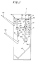
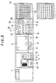
- Fig.1 is a front longitudinal sectional view showing an embodiment of the sheet discharge processing device of the present invention.
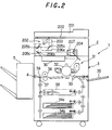
- Fig.2 is a sectional view showing the overall structure of the digital image forming apparatus including the sheet discharge processing device of the present invention.
- This digital image forming apparatus is a digital copying machine.
- the digital copying machine body 1 is mainly constituted by a scanner section 2 and a laser recording section 3.
- the scanner section 2 is constituted by an original-placed table 200 made of transparent glass, a reversible automatic document feeder (RADF) 201 for automatically feeding an original onto the original-placed table 200, and an original image read unit, i.e., a scanner unit 202, for scanning and reading an image on an original placed on the original-placed table 200.
- a reversible automatic document feeder RDF
- a scanner unit 202 for scanning and reading an image on an original placed on the original-placed table 200.
- the original image read by the scanner section 2 is sent as image data to an image data input section (to be described later), in which predetermined image processing is performed for the image data.
- the RADF 201 is a device for automatically feeding originals set on an original tray (not shown), one by one, onto the original-placed table 200.
- the RADF 201 is constituted by a convey path for one-sided originals, a convey path for double-sided originals, convey path switching means, and the like to allow the scanner unit 202 to read one or two surfaces of an original in accordance with selection made by the operator.
- many patent applications have been filed, and many devices have become commercially available, and hence a further description of this device will be omitted.
- the scanner unit 202 as a part of the scanner section 2 for reading an image on an original placed on the original-placed table 200 comprises a first scanning unit 206a having a lamp reflector assembly 203 for exposing the original surface and a first reflecting mirror 205a for reflecting light reflected by the original to guide the reflected light image from the original to the photoelectric conversion element 204, a second scanning unit 206b having second and third reflecting mirrors 205b and 205c for guiding the reflected light image from the first reflecting mirror 205a to the photoelectric conversion element (CCD) 204, an optical lens body 207 for forming the reflected light image from the original on the element (CCD) 204, which serves to convert the reflected light image into an electrical signal, via the reflecting mirrors 205a, 205b, and 205c, and the CCD 204 for converting the reflected light image from the original into an electrical image signal.
- a first scanning unit 206a having a lamp reflector assembly 203 for exposing the original surface and a first reflecting mirror
- the scanner unit 202 is moved along the lower surface of the original-placed table 200 to read original images.
- the first scanning unit 206a is driven to travel along the original-placed table 200 from left to right at a constant velocity V
- the second scanning unit 206b is controlled to travel parallel in the same direction at a velocity V/2.
- This laser recording section 3 includes a convey system for a sheet as paper on which image is to be formed, a laser write unit 30, and an electrophotographic process section 31 for forming an image.
- the laser write unit 30 includes a semiconductor laser for emitting a laser beam in accordance with image data read by the scanner unit 202 and read out from the memory, or image data transferred from an external apparatus, a polygon mirror for performing constant-angular-velocity deflection of the laser beam, an f- ⁇ lens for correcting the laser beam having undergone constant-angular-velocity deflection to undergo constant-velocity deflection on a photosensitive drum 32 as a part of the electrophotographic process section 31, and the like.
- the electrophotographic process section 31 includes a charger, a developing unit, a transfer unit, a peeling unit, a cleaning unit, and a charge remover around the photosensitive drum 32 as a known member.
- the sheet convey system includes a convey section 33 for conveying a sheet to the transfer position, of the electrophotographic process section 31 for performing the above image forming operation, at which the transfer unit is placed, cassette paper feeders 34a and 34b for feeding a sheet into the convey section 33, a manual paper feeder 35 for feeding a sheet of a necessary size, as needed, a fixing unit 36 for fixing the image transferred onto the sheet, i.e., the toner image, on the sheet, a switchback convey path 37 for reversing the sheet to allow an image to be formed on the lower surface of the sheet having undergone the fixing operation, i.e., to allow images to be formed on the upper and lower surfaces of the sheet, and an intermediate tray 38 for storing a sheet which passes through the convey path 37.
- a convey section 33 for conveying a sheet to the transfer position, of the electrophotographic process section 31 for performing the above image forming operation, at which the transfer unit is placed
- cassette paper feeders 34a and 34b for feeding a sheet into the convey section 33
- a switching pawl 39 for switching the convey path of a sheet to the switchback convey path 37 is placed on the downstream side of the fixing unit 36.
- the switching pawl 39 switches the convey path of a sheet having undergone image formation to the convey path through which the sheet is conveyed to a sheet discharge processing device 5 via a discharge section 4.
- Sheets of predetermined sizes desired by the operator are stored in the cassette paper feeders 34a and 34b of the above sheet convey system.
- the manual paper feeder 35 is used to feed a small number of sheets with sizes desired by the operator. The operator selects one of the paper sizes of the paper feed cassettes or the manual paper feeder 35 to feed a sheet of a desired size.
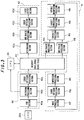
- Fig.3 is a block diagram showing the image processing unit included in the digital copying machine body 1 in Fig.2.
- the image processing unit included in the digital copying machine body 1 has an image data input section 40, an image processing section 41, an image data output section 42, a memory 43 constituted by a RAM (random access memory), a hard disk, and the like, and a central processing unit (CPU) 44.
- CPU central processing unit
- the image data input section 40 includes a CCD section 40a, a histogram processing section 40b, and an error diffusion processing section 40c.
- the image data input section 40 binarizes the original image data received from the CCD 204, processes the image data by the error diffusion method while generating a histogram as a binary digital amount, and temporarily stores the data in the memory 43.
- density information (histogram data) is obtained by adding digital signals outputted from the CCD section 40a for each of the 256-level pixel densities.
- the obtained histogram data is sent to the central processing unit 44, or is sent as pixel data to the error diffusion processing section 40c, as needed.
- an 8-bit/pixel digital signal outputted from the CCD section 40a is converted into 1-bit (binary) data by the error diffusion method as a type of pseudo-halftone processing, i.e., a method of reflecting a binarization error on binarization determination of adjacent pixels, and a re-distribution operation is performed to faithfully reproduce the local area densities of the original.
- pseudo-halftone processing i.e., a method of reflecting a binarization error on binarization determination of adjacent pixels
- the image processing section 41 includes multivalue processing sections 41a and 41b, a synthetic processing section 41c, a density conversion processing section 41d, a variable magnification processing section 41e, an image process section 41f, an error diffusion processing section 41g, and a compression processing section 41h.
- the image processing section 41 serves to finally convert input image data into image data desired by the operator.
- the image processing section 41 is designed to perform image processing until the processed data is finally stored as converted output image data in the memory 43. Note that the above processing sections included in the image processing section 41 operate as needed, but may not operate in some case.
- the multivalue processing sections 41a and 41b convert data binarized by the error diffusion processing section 40c into 256-level data again.
- the synthetic processing section 41c selectively performs a logical operation for each pixel, i.e., an "or” logical sum operation, an "and” logical product operation, or an exclusive-OR operation.
- Data to be subjected to this operation includes pixel data stored in the memory 43 and bit data from a pattern generator (PG).
- PG pattern generator
- the variable magnification processing section 41e performs interpolation processing with input known data in accordance with a designated magnification to obtain pixel data (density value) for each pixel after variable magnification processing. As a result, after variable magnification processing in the subscannig direction, variable magnification processing in the main scanning direction is performed.
- the image process section 41f performs various image processes for input pixel data, and acquires information about a data string by, for example, extracting features.
- the error diffusion processing section 41g performs the same processing as that performed by the error diffusion processing section 40c of the image data input section 40.
- the compression processing section 41h compresses binary data by run-length coding. Image data is compressed in the final processing loop when final output image data is completed.
- the image data output section 42 includes a restoration section 42a, a multivalue processing section 42b, an error diffusion processing section 42c, and a laser output section 42d.
- the image data output section 42 restores the compressed image data stored in the memory 43, converts the data into the original 256-level data, performs error diffusion of quaternary data as a halftone expression smoother than binary data, and transfers the resultant data to the laser output section 42d.
- the restoration section 42a restores the image data compressed by the compression processing section 41h.
- the multivalue processing section 42b performs the same processing as that performed by the multivalue processing sections 41a and 41b of the image processing section 41.
- the error diffusion processing section 42c performs the same processing as that performed by the error diffusion processing section 40c of the image data input section 40.
- digital pixel data is converted into an ON/OFF signal for the laser on the basis of a control signal from a sequence controller (not shown), and the semiconductor laser in the laser write unit 30 is turned on/off to write an electrostatic latent image on the photosensitive drum 32.
- Data to be processed by the image data input section 40 and the image data output section 42 are basically stored as binary data in the memory 43 to reduce the capacity of the memory 43.
- data may be processed in the form of quaternary data in consideration of a deterioration in image quality.
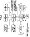
- Fig.4 shows how the central processing unit (CPU) 44 manages the operations of the respective sections in the overall digital copying machine body 1.
- the CCD 204, the image data input section 40, the image processing section 41, the image data output section 42, the memory 43, and the central processing unit (CPU) 44 are the same as those described above, and hence a description thereof will be omitted.
- the central processing unit 44 manages the respective mechanisms, e.g., the RADF 201, the scanner section 2, and the laser recording section 3 described with reference to Fig.2, which constitute the digital copying machine by sequence control, and outputs control signals to the respective sections.
- the respective mechanisms e.g., the RADF 201, the scanner section 2, and the laser recording section 3 described with reference to Fig.2, which constitute the digital copying machine by sequence control, and outputs control signals to the respective sections.
- An operation board unit 45 constituted by an operation panel is connected to the central processing unit 44 so as to allow mutual communication.
- the operation board unit 45 transfers a control signal to the central processing unit 44 in accordance with the copy mode set by the operator, thereby controlling the operation of the digital copying machine body 1 in accordance with various set modes.
- the central processing unit 44 transfers a control signal indicating the operation state of the digital copying machine body 1 to the operation board unit 45.
- the operation board unit 45 then causes the display section to display the operation state in accordance with this control signal to show the operator the current state of the apparatus.
- a sorter control unit 46 is a control unit for managing the operation of the discharge processing device for sorting copies and the like outputted from the digital copying machine body 1. That is, the sorter control unit 46 is the control unit for performing various control operations in the sheet discharge processing device 5 in Fig.1.
- An image data communication unit 47 serves to communicate pieces of information such as image information and control signals with other digital image devices.
- Fig.5 is a plan view showing an example of the operation panel of the operation board unit 45 in the digital copying machine body 1.
- a touch panel liquid crystal display device 6 is placed in the central portion of the operation panel, and various mode setting keys are arranged around the touch panel liquid crystal display device 6.
- a screen switching designation area for switching the current screen to a screen for allowing the operator to select an image editing function is always displayed on the screen of the touch panel liquid crystal display device 6.
- this area is directly pressed with a finger of the operator, a list of editing functions is displayed on the liquid crystal screen to allow the operator to select an image editing function.
- the desired editing function is set.
- Reference numeral 7 denotes a dial for adjusting the brightness of the screen of the touch panel liquid crystal display device 6.
- Reference numeral 8 denotes an automatic magnification setting key for setting a mode of automatically selecting a magnification; 9, a zoom key for setting a copy magnification in increments of 1%; 10 and 11, fixed magnification keys for reading out and selecting fixed magnifications; and 12, a one-to-one magnification key for restoring the copy magnification to the standard magnification (one-to-one magnification).
- Reference numeral 16 denotes a copy count setting key for setting the number of copies; 17, a clear key to be operated to clear the number of copies or stop a continuous copy operation; 18, a start key for designating the start of a copy operation; 19, an all cancel key for canceling all the currently set modes and restoring the standard state; 20, an interrupt key to be operated to perform a copy operation for another original during a continuous copy operation; 21, an operation guide key which is operated, when the operator does not know how to operate the copying machine, to display an operation method of the copying machine with a message; and 22, a message forward scrolling key for displaying the remaining part of the message displayed upon operation of the operation guide key 21.
- Reference numeral 23 denotes a double-sided mode setting key for setting the double-sided copy mode; and 24, a discharge processing mode setting key for setting the operation mode of the sheet discharge processing device 5 for sorting copies discharged from the copying machine.
- Reference numerals 25 to 27 denote setting keys associated with the printer and facsimile modes. More specifically, reference numeral 25 denotes a memory transmission mode key for setting a mode of temporarily storing transmission original data in a memory and transmitting the data afterward; 26, a copy/fax ⁇ printer mode switching key for switching the mode of the digital copying machine between the copy mode and the fax ⁇ printer mode; and 27, a one-touch dial key for allowing the operator to make a call to a destination, the telephone number of which has been stored in advance, with a one-touch operation.
- the sheet discharge processing device 5 receives sheets having undergone image formation in the above digital copying machine body 1, aligns them in a desired direction, and sorts them in a desired page order.
- the sheet discharge processing device 5 reverses/conveys sheets in accordance with the printer mode or the facsimile mode.
- the sheet discharge processing device 5 reverses/discharges sheets or discharges sheets without changing their postures in accordance with an instruction manually inputted through the above operation panel.
- First convey rollers 51 for conveying a conveyed sheet are arranged at the inlet 50.
- the discharge processing device 5 has three discharge sections for discharging sheets, conveyed by the first convey rollers 51, to the outside through the discharge processing device 5.
- One of the discharge sections is a straight convey path 52 for conveying a sheet from the first convey rollers 51 toward the downstream side in the sheet convey direction without changing the posture of the sheet.
- the straight convey path 52 extends in the horizontal direction.
- Second convey rollers 53 for conveying a sheet and first discharge rollers 54 for discharging a sheet are arranged midway along the straight convey path 52.
- a first discharge tray 55 for receiving a sheet with the image-bearing surface facing up is placed in correspondence with the first discharge rollers 54 to protrude from the discharge processing device 5.
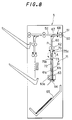
- the second discharge section is a reverse convey path 56 that branches off from the straight convey path 52.
- the reverse convey path 56 is used to discharge a sheet with the image-bearing surface facing down, and extends in the vertical direction.
- Third convey rollers 57 and second discharge rollers 58 are arranged midway along the reverse convey path 56.
- a second discharge tray 59 for receiving a discharged sheet is placed below the first discharge tray 55 in correspondence with the second discharge rollers 58 to protrude from the discharge processing device 5.
- the image-bearing surface of a sheet conveyed into the reverse convey path 56 faces left in Fig.1. In this arrangement alone, when a sheet is discharged onto the second discharge tray 59, it is impossible to define which direction the image-bearing surface faces.
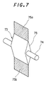
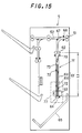
- An alignment guide member 73 is rotatably placed in the sheet storing section 61.
- the alignment guide member 73 is a part of sheet alignment means for reliably guiding a sheet conveyed into the sheet storing section 61 thereinto, and switching the directions in which sheets are stored in the sheet storing section 61 in consideration of the page order of the sheets.
- the alignment guide member 73 has a plurality of rotating members 75 fixed to a rotating shaft 74 at predetermined intervals.
- the rotating shaft 74 is rotated by a motor (not shown).
- Each rotating member 75 is made of an elastic member such as a rubber member, and has paddles 75a and 75b integrally formed to be symmetrical.
- the paddles 75a and 75b serve to guide sheets and enable alignment of the sheets.
- the stapler 63 operates to complete a stapling operation regardless of whether the current mode is the copy mode or the printer mode (S6). Upon completion of this stapling operation, the switching pawl 64 is opened (S7) to discharge the bundle of sheets having undergone stapling processing onto the third discharge tray 65.
- the sheet alignment device 71 having the above structure, if sheets to be processed have the same length, i.e., the same length in the feed direction, the sheet can be effectively aligned in accordance with rotation control of the alignment guide member 73. There are demands for a sheet alignment device which can efficiently perform sheet alignment even if sheets to be processed have different lengths.
- the first detection sensor 68 for detecting conveyance of a sheet can be used to detect the size of a conveyed sheet. More specifically, a time counting operation is started by using a timer when the leading end of a sheet is detected by the first detection sensor 68, and the time counting operation is stopped when the trailing end of the sheet is detected.
- the size of the sheet can be easily obtained on the basis of the time counted by the timer. Not only the size of a standard sheet but also the size of a non-standard sheet can be detected. Alignment of the vertical position of the lower sheet storing section 61d in the vertical position can be controlled on the basis of the detected size so as to reliably cause the lower paddle to press the trailing end of the sheet to be processed against one guide plate.
- the alignment guide member 73 is further rotated to cause the paddle 75a to press the overall bundle of stored sheets against the second guide plate 61b. Thereafter, the rotation of the alignment guide member 73 is stopped.
- Fig.12B shows this state. As shown in Fig.12B, the trailing end portion of the sheets P is clamped between the second guide plate 61b and the paddle 75a, and the aligned bundle of sheets is kept standstill, thereby allowing the stapler 63 to staple the sheets without displacing them.
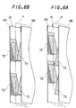
- the alignment guide member 73 is rotated and stopped such that the paddles 75a and 75b become parallel to the guide plates 61a and 61b of the sheet storing section 61, as shown in Fig.16A.
- the frictional resistance between the alignment guide member 73 and the sheet P decreases to facilitate removal of the sheet P.
- the end portions of the alignment guide member 73 are the paddles 75a and 75b made of elastic members, even if the sheet P is forcibly removed, the paddles are transformed only, but damage such as breakage of the paddles can be prevented.
- the third detection sensor 70 detects a sheet P while it is conveyed to the sheet storing section 61 by the fourth convey rollers 62.
- This detection state i.e., the time taken for the trailing end of the sheet P to pass through the third detection sensor 70 after detection of the leading end of the sheet P is determined in accordance with the size of the sheet subjected to discharge processing. Since the sheet size is detected in advance, as described above, if the sheet P is detected by the third detection sensor 70 after the lapse of the time taken to detect the leading end of the sheet P to the trailing end thereof, a convey failure in the state shown in Fig.16A can be detected. In response to detection by this convey failure detection means, the alignment guide member 73 may be driven to rotate to a position where it does not interfere with the sheet to be processed.
- the alignment guide member 73 can be retracted to the position where it does not regulate the sheet in response to the detection. With this operation, the failed sheet can be removed, and damage to the alignment guide member 73 can be prevented.
- the sheet P conveyed by the fourth convey rollers 62 passes between the guide members 78a and 78b first, and part of the sheet P rides on the projections 79 on the guide member 78a side.
- the sheet P is then continuously conveyed in a rubbed state.
- the sheet P is conveyed while it has wavy recesses (or projections) in the longitudinal direction at portions corresponding to the projections 79.
- the stiffness of the sheet P is reinforced, and the sheet P has no flection. Therefore, occurrence of a jam caused by bending of the sheet or the like is suppressed, and the sheet can be reliably conveyed into the sheet storing section 61.
- the holding force of the sheet in the longitudinal direction can be increased to allow more reliably conveyance of the sheet.
- the guide plates 61a and 61b constituting the sheet storing section 61 may substitute for the guide members 78.
- convex projections may be formed on upper portions of the guide plate 61a which correspond to the fourth convey rollers 62.
- the alignment guide members 73 are preferably arranged at positions shifted from the positions of the projections 79 in the convey direction.
- the above alignment control can be performed. According to the present invention, therefore, by inputting information indicating the order of image formation, switching control of the alignment guide member 73 and control of the rotation direction thereof are performed to align sheets in the first or second order. With this control, image-bearing sheets stored in the sheet storing section 61 are sequentially aligned in the page order.
- the convey speed of the first convey rollers 51 is made coincide with the speed at which a sheet is conveyed from the digital copying machine body 1.
- the convey speed of the fourth convey rollers 62 for conveying a sheet to the sheet storing section 61 is therefore set to be higher than the convey speed of the first convey rollers 51.
- the sheet convey cycle can be substantially prolonged as compared with the cycle in which sheets are conveyed from the digital copying machine body 1. Consequently, a sufficient time can be ensured to rotate the alignment guide member 73.
- the sheet discharge processing device of the present invention since the stored state of sheets in the sheet storing section is changed in accordance with the order of image formation, the use of only one sheet storing section enables alignment without upsetting the page order of image-bearing sheets and allows post-processing in the aligned state.
- this device need not have another convey route for, e.g., reversing and sorting sheets as in the conventional device, and the overall structure can be simplified, allowing a reduction in size and a great reduction in cost.
- sheets can be shifted and aligned at the same time by only rotating the alignment guide members for sheet alignment, the sheets can be reliably aligned.
- the mechanism for alignment can be greatly simplified.
- the switching pawls 66 and 67 are switched to the states shown in Fig.1 so a sheet conveyed by the first convey rollers 51 travels straight in the straight convey path 52 and is discharged onto the first discharge tray 55 by the second convey rollers 53 and the first discharge rollers 54 with the image-bearing surface facing up. That is, sheets are sequentially stacked on the first discharge tray 55 with the image-bearing surfaces facing up.
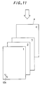
- the first discharge tray 55 is constituted by many trays constituting a sorter.
- images are formed on sheets one by one from the last page to the start page.
- this operation is to be repeated by the number of times corresponding to the desired number of sets, sheets are stacked on the first discharge tray 55 without being reversed.
- the sheets are therefore stacked on the first discharge tray 55 with the sheet on which the image of the last page is formed being located at the lowermost position and the sheet on which the image of the start page is formed being located at the uppermost position. These sheets are stacked with the image-bearing surfaces facing up, and are discharged onto the first discharge tray 55 in the page order.
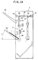
- the switching pawls 66 and 67 in the discharge processing device 5 are switched as follows. As shown in Fig.19, the switching pawl 67 is positioned to open the straight convey path 52, and the switching pawl 66 is positioned to close the convey path to the first discharge rollers 54 and open the reverse convey path 56.
- air blown from the fan 80 is used in this embodiment.
- the fan 80 is driven at a predetermined timing, air is blown against the opposite surface of the sheet to the image-bearing surface.
- the sheet is discharged onto the second discharge tray 59 with the image-bearing surface facing down, as shown in Fig.19.
- the second detection sensor 69 is placed on the upstream side of the second discharge rollers 58 in the convey direction.
- the fan 80 is driven in response to detection of the trailing end of the sheet by the second detection sensor 69.
- the fan 80 is driven to blow air in the direction of the second discharge tray 59. With this operation, the leading end of the sheet comes into contact with the second discharge tray 59, and the sheet is discharged as if it fell/rotated about the contact portion as a fulcrum toward the second discharge tray 59.
- This time t may be set to the time taken for a sheet to travel the distance between the second detection sensor 69 and the second discharge rollers 58. That is, the time t may be set to the sum of the time obtained by dividing the above distance by the convey speed of a sheet and a time set in consideration of an error.
- a sheet is discharged onto the second discharge tray 59 in a reversed state at the timing when the fan 80 is started.
- a sheet undergoes a reversing effect when it is only conveyed into the reverse convey path 56, and is discharged onto the second discharge tray 59 in a reversed state.
- switchback conveyance of a sheet need not be performed in a reverse convey path, i.e., the convey direction of a sheet in a reversed state need not be reversed. For this reason, even if the sheet convey cycle is short, sheets can be sequentially reversed/discharged, and the device can cope with high-speed processing without increasing the covey speed at the reverse convey path 56.
- a sheet needs to be discharged by the second discharge rollers 58 along the guide plate 82 placed in a vertical posture and serving as a part of the reverse convey path 56 without any curl.
- the sheet P is discharged such that its leading end is separated from the guide surface of the guide plate 82 (to the left in Fig.19).
- the possibility that the leading end of the sheet P is biased in the direction to further separate from the guide plate 82 increases.
- the sheet P may be discharged without being reversed.
- increasing the stiffness of the sheet P to discharge it along the guide plate 82 is effective in preventing the sheet P from being discharged in such a manner that the leading end is separated from the guide plate 82 owing to a curl or the like. That is, correction means for increasing the stiffness of a sheet is preferably placed near the second discharge rollers 58.
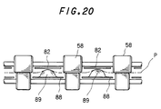
- Fig.20 shows an example of this correction means.
- guide members 88 for guiding the sheet P to the guide plate 82 in the process of discharging the sheet P onto the second discharge tray 59 are arranged at the exit portions between the second discharge rollers 58.
- the guide members 88 between the second discharge rollers 58 arranged on the reverse convey path 56 have convex projections 89 on the surfaces opposing the guide plate 82.
- the holding force of the sheet in the longitudinal direction can be increased to allow more reliably conveyance of the sheet.
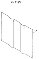
- the sheet P has wavy recesses (or projections) parallel to the feed direction, any curl of the sheet P can be corrected in a direction perpendicular to the recesses, thereby preventing the sheet P from separating from the guide plate 82 owing to the curl.
- the sheet P is discharged downward along the guide plate 82 with the leading end dropping vertically, and hence can be reliably discharged onto the second discharge tray 59 in a reversed state upon driving of the above fan 80 for blowing air.
- the sheet may be drawn to the guide plate 82 before it is discharged, instead of using the above means for reinforcing the stiffness of a sheet.
- This operation can be easily performed by rotating the fan 80 in the reverse direction, as shown in Fig.1.
- the motor for driving the fan 80 When the motor for driving the fan 80 is capable of rotating in the forward and reverse directions, and is rotated in the reverse direction, air is drawn to draw a sheet toward the guide plate 82.
- the fan 80 When the trailing end of the sheet is detected by the second detection sensor 69, the fan 80 is rotated in the forward direction to blow air. With this operation, the sheet is vertically discharged along the guide plate 82, and is finally reversed/discharged onto the second discharge tray 59.
- the suction force is set so as not to interfere with conveyance of a sheet. That is, the suction force is set to allow a sheet to be fed by the second discharge rollers 58.
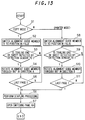
- Fig.22 is a flow chart showing a procedure for controlling the above operation. This control operation will be described with reference to this flow chart. This control is equivalent to the control performed by the sorter control unit 46 in Fig.4, and is performed to control the operation of the fan 80.
- the current mode is checked by the sorter control unit (FCU) 46 for sheet discharge processing. That is, the sorter control unit 46 checks whether the copy mode is set. If the copy mode is determined, the switching pawls 66 and 67 are set in the states shown in Fig.1.
- the printer or facsimile mode is determined.
- the switching pawls 66 and 67 are position-controlled to the states shown in Fig.19.
- the sheet is conveyed into the reverse convey path 56 by the first and second convey rollers 51 and 53.
- the fan 80 is rotated in the reverse direction (S22). The suction force at this time is set in the above manner, so air is drawn without interfering with a discharge operation for the sheet.
- the fan 80 is not rotated in the forward direction for a long period of time but is rotated for a predetermined period of time.
- a predetermined time T is therefore set in the timer at the same time the fan 80 is rotated in the forward direction (S25). More specifically, this predetermined time T is a short period of time and set to the time required to reverse a sheet. For example, the time T is one second or less and set to the time taken for a sheet to fall onto the second discharge tray 59 after air is blown against the rear surface of the sheet. For this reason, the predetermined time T which is a short period of time during which air is blown is set in the timer. If this time is too long, a discharged sheet may float in the air and moves out of the second discharge tray 59.
- means for reliably conveying a sheet along the guide plate 82 can also serve as means for reversing the sheet. Therefore, a reduction in the size of the device can be satisfactorily attained, and the factor that causes an increase in cost can be eliminated.
- a distance L between the second discharge rollers 58 and the second discharge tray 59 is set to be almost equal or slightly larger than the length of a sheet to be discharged, i.e., the length of a sheet in the convey direction. For this reason, when the leading end of a sheet passes through the second discharge rollers 58 and reaches the second discharge tray 59, the trailing end of the sheet is passing through the second discharge rollers 58.
- the sheet When the rear surface of the sheet is biased by, for example, biasing means for blowing air in this state, the sheet is reversed/rotated about the contact position as a fulcrum where the leading end of the sheet is in contact with the second discharge tray 59, and is discharged onto the second discharge tray 59.
- the distance between the second discharge rollers 58 and the second discharge tray 59 is set to be not less than the minimum size that allows processing of a sheet and not more than the maximum size that allows processing of a sheet.
- air is preferably blown at a position near the middle of the distance between the second discharge rollers 58 and the second discharge tray 59 or an upper position. If, however, air is blown against a portion near the leading end of the sheet, the leading end of the sheet is greatly separated from the guide plate 82. Consequently, the sheet may not be reversed/rotated about the leading end as a fulcrum, and may be subjected to discharge processing without being properly reversed. In order to eliminate such an inconvenience, the position of the fan 80 is determined in the above manner.
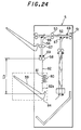
- the distance between the second discharge rollers 58 and the second discharge tray 59 is set in the above manner, and the position of the reversing/biasing means constituted by the fan 80 is fixed. More preferably, however, the above distance is changed in accordance with the size of a sheet to be processed.
- the distance between the second discharge rollers 58 and the second discharge tray 59 is preferably set in accordance with the size of a sheet to be processed.
- the second discharge tray 59, the fan 80, and the guide plate 82 are supported on a single support member 84 to be movable in the vertical direction.
- the setting in Fig.23 corresponds to the minimum size (La) of a sheet to be processed.
- the setting in Fig.24 corresponds to the maximum size (Lb) of a sheet to be processed.
- the distance L between the second discharge rollers 58 and the second discharge tray 59 can be set in accordance with the sheet size.
- the size of a sheet is detected when the sheet is processed in the digital copying machine body 1 as an image forming apparatus.
- a sheet of a selected size is to be fed from the cassette paper feeder 34a or 34b, and information indicating this sheet size is sent to the discharge processing device 5, the vertical position of the support member 84 can be easily adjusted/controlled in accordance with the sheet size.
- the support member 84 is vertically moved on the basis of the size of a sheet to be processed.
- the fan 80 is also supported on the support member 84 and vertically moved.
- the fan 80 is preferably located at least in the middle of the distance between the second discharge rollers 58 and the second discharge tray 59 or an upper position when a sheet of the maximum size is to be processed. If the fan 80 is located below the middle of the above distance, the leading end of a sheet may separate from the second discharge tray 59, and the sheet may not be accurately reversed/rotated about the leading end. If the fan 80 is located above the middle position in the mode of processing a sheet of the maximum size, the fan 80 is located above even the center of a sheet smaller in size than a sheet of the maximum size.
- the fan 80 blows air against the rear surface of the sheet. As a result, the sheet falls onto the opposite side to the rear surface to be discharged onto the second discharge tray 59.
- the present invention is not limited to the structure shown in Figs.23 and 24.
- the fan 80 need not be mounted on the support member 84 together with the second discharge tray 59. That is, only the second discharge tray 59 may be mounted to be vertically movable. In this case, the same effect as described above can be obtained by vertically moving a guide plate 82a below an opening portion 81 of the fan 80 in addition to the second discharge tray 59.
- the sheet can be reversed more reliably by fixing the fan 80 to a position corresponding to the center of the sheet to be processed or an upper position. If the fan 80 is fixed at a position higher than the second discharge tray 59 by La/2 or more (where La is the distance between the second discharge rollers 58 and the second discharge tray 59 in the mode of processing a sheet of the minimum size), the fan 80 can perform reversing processing of sheets of any sizes at upper positions.
- the reversing/biasing means for reversing a sheet by blowing air is used to reverse a sheet by biasing the rear surface of the sheet.
- This reversing/biasing means is not limited to the means for blowing air using the fan 80.
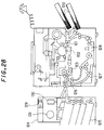
- a rotating member 85 which rotates in the manner shown in Fig.26 may be operated at the driving timing of the fan 80. With this operation as well, a sheet can be reversed.
- one end 85a of the rotating member 85 is axially rotatably supported, and a free end 85b is located in correspondence with the rear surface of a sheet.
- the rotating member 85 makes one revolution in the counterclockwise direction (indicated by the arrow) in Fig.26, the rear surface of the sheet P to be discharged is pushed to the left by the free end 85b of the rotating member 85.
- the sheet falls onto the second discharge tray 59 in the same manner as in the case of an air blowing operation.
- the rotating member 85 need not make one revolution, and may be reciprocally driven to be restored to the original position after it rotates through a necessary angle. It suffices if this angle is set to 90°. Alternatively, this angle may be set to at least 30° at which the free end 85b protrudes from the guide plate 82 and can apply a biasing force to the rear surface of a sheet.
- an angle ⁇ at which the second discharge tray 59 is placed is preferably set to 30° or more with respect to the horizontal position, as shown in Figs.19 or 26. If, however, the angle ⁇ is set to 90°, sheets are not reversed and cannot be discharged in the order of image formation. For this reason, the angle ⁇ needs to be smaller than 90°.
- the angle ⁇ is preferably set to 70° or less. If, for example, the stiffness of a sheet is low, the discharged sheet may slip off. For this reason, it is more preferable that the angle ⁇ be set to be smaller than 70°.
- a sheet can be reversed without using any switchback convey path through which the feed direction of a sheet is reversed after the sheet is reversed as in the conventional device. For this reason, the overall device can be reduced in size, and at the same time, the cost can be greatly reduced.
- discharge processing of sheets can be performed without setting the convey cycle to a value equal to or larger than the size of a sheet to be processed. For this reason, the sheet convey cycle can be shortened to allow the device to easily cope with high-speed processing. Since the convey speed need not be set to be higher than the image formation speed, in particular, discharge processing can be performed at a speed corresponding to the convey speed for high-speed image processing without posing problems associated with a sheet convey failure, a jam, and the like.
- Discharged sheets can be sorted in the order of image formation.
- processing of sheets can be performed in accordance with the size of each sheet without decreasing the processing speed.
- the sheet can be reliably reversed. If adjustment is performed in accordance with the size of a sheet in order to process the sheet with its leading end in contact with the discharge tray, sheet reversing processing can be reliably performed regardless of the size of a sheet.
- the means for performing a reversing operation is used to guide the sheet in a vertical state so as to reliably perform a reversing operation.
- the above means have the two functions, an increase in the size of the sheet discharge processing device can be prevented.
- the correction means for reinforcing the stiffness of a sheet to be discharged the sheet can be reliably discharged and accurately reversed.
Landscapes
- Engineering & Computer Science (AREA)
- Mechanical Engineering (AREA)
- Pile Receivers (AREA)
- Paper Feeding For Electrophotography (AREA)
- Separation, Sorting, Adjustment, Or Bending Of Sheets To Be Conveyed (AREA)
- Folding Of Thin Sheet-Like Materials, Special Discharging Devices, And Others (AREA)
Applications Claiming Priority (6)
| Application Number | Priority Date | Filing Date | Title |
|---|---|---|---|
| JP268555/95 | 1995-10-17 | ||
| JP26855595A JP3281772B2 (ja) | 1995-10-17 | 1995-10-17 | シート排出処理装置 |
| JP26855595 | 1995-10-17 | ||
| JP27750995A JP3268175B2 (ja) | 1995-10-25 | 1995-10-25 | シート後処理装置 |
| JP277509/95 | 1995-10-25 | ||
| JP27750995 | 1995-10-25 |
Publications (3)
| Publication Number | Publication Date |
|---|---|
| EP0769467A2 true EP0769467A2 (de) | 1997-04-23 |
| EP0769467A3 EP0769467A3 (de) | 1998-09-30 |
| EP0769467B1 EP0769467B1 (de) | 2002-06-05 |
Family
ID=26548370
Family Applications (1)
| Application Number | Title | Priority Date | Filing Date |
|---|---|---|---|
| EP96116112A Expired - Lifetime EP0769467B1 (de) | 1995-10-17 | 1996-10-08 | Bogenausgabevorrichtung |
Country Status (3)
| Country | Link |
|---|---|
| US (2) | US5971394A (de) |
| EP (1) | EP0769467B1 (de) |
| DE (1) | DE69621553T2 (de) |
Cited By (2)
| Publication number | Priority date | Publication date | Assignee | Title |
|---|---|---|---|---|
| EP0960744A3 (de) * | 1998-05-29 | 2001-03-14 | Sharp Kabushiki Kaisha | Blattnachbearbeitungsgerät |
| WO2007039164A1 (de) * | 2005-10-03 | 2007-04-12 | Siemens Aktiengesellschaft | Ablagefach für einen fallenden flachen gegenstand |
Families Citing this family (23)
| Publication number | Priority date | Publication date | Assignee | Title |
|---|---|---|---|---|
| EP1440814B1 (de) * | 1997-11-14 | 2008-01-16 | Sharp Kabushiki Kaisha | Nachverarbeitungsvorrichtung für Bögen |
| US6170818B1 (en) * | 1997-11-28 | 2001-01-09 | Diebold, Incorporated | Currency recycling automated banking machine media gate |
| JPH11322157A (ja) * | 1998-05-15 | 1999-11-24 | Hitachi Koki Co Ltd | シート搬送装置 |
| US6250631B1 (en) * | 1998-06-23 | 2001-06-26 | Kyocera Mita Corporation | Sheet handling unit |
| JP2000153954A (ja) * | 1998-11-20 | 2000-06-06 | Omron Corp | 綴じ装置 |
| US6672586B2 (en) * | 1999-07-23 | 2004-01-06 | Canon Kabushiki Kaisha | Sheet processing apparatus and method of controlling same, sheet processing method, and storage media therefor |
| JP2001154436A (ja) | 1999-11-24 | 2001-06-08 | Sharp Corp | 画像形成装置 |
| JP2001203834A (ja) * | 2000-01-19 | 2001-07-27 | Canon Inc | 複合装置及びその制御方法及び情報処理システム及び記憶媒体 |
| JP3981230B2 (ja) | 2000-01-21 | 2007-09-26 | シャープ株式会社 | 画像形成装置 |
| US6478490B2 (en) * | 2000-12-01 | 2002-11-12 | Hewlett-Packard Co. | Printer media transport apparatus and method |
| FR2823965B1 (fr) * | 2001-04-30 | 2003-10-31 | Georgia Pacific France | Distributeur d'articles en papier |
| US6644654B1 (en) * | 2002-07-03 | 2003-11-11 | Xerox Corporation | Sheet order gate |
| US20050093222A1 (en) * | 2003-10-29 | 2005-05-05 | Kabushiki Kaisha Toshiba | Sheet feeder in image forming apparatus |
| DE102004002645A1 (de) * | 2004-01-17 | 2005-08-11 | Eastman Kodak Co. | Verfahren und Steuerungseinrichtung zum Transportieren von Bedruckstoff |
| JP2005247476A (ja) * | 2004-03-03 | 2005-09-15 | Ricoh Co Ltd | 画像形成装置 |
| JP4511458B2 (ja) * | 2005-12-29 | 2010-07-28 | 東芝テック株式会社 | 用紙後処理装置 |
| DE102006027124A1 (de) * | 2006-06-12 | 2007-12-13 | Heidelberger Druckmaschinen Ag | Abfallgebläse für eine Bogenstanz- und Prägemaschine |
| JP5622073B2 (ja) * | 2010-02-08 | 2014-11-12 | 株式会社リコー | 給紙装置及び画像形成装置 |
| JP5521637B2 (ja) * | 2010-02-25 | 2014-06-18 | 株式会社リコー | シート搬送装置及び画像形成装置 |
| JP5625010B2 (ja) * | 2012-03-22 | 2014-11-12 | 京セラドキュメントソリューションズ株式会社 | 画像形成装置 |
| US9336589B2 (en) * | 2012-07-06 | 2016-05-10 | Horizon International Inc. | Sheet feeder |
| US10035672B2 (en) | 2014-06-05 | 2018-07-31 | Hewlett-Packard Development Company, L.P. | Printing device |
| US9551972B2 (en) * | 2014-12-19 | 2017-01-24 | Canon Kabushiki Kaisha | Image forming apparatus |
Family Cites Families (32)
| Publication number | Priority date | Publication date | Assignee | Title |
|---|---|---|---|---|
| US3867026A (en) * | 1970-08-03 | 1975-02-18 | Minolta Camera Kk | Electrophotographic copier of transfer type |
| US4026543A (en) * | 1975-11-28 | 1977-05-31 | International Business Machines Corporation | Document article handling control |
| US4040616A (en) * | 1976-01-14 | 1977-08-09 | Xerox Corporation | Sheet turn around/inverter |
| DE2757848A1 (de) * | 1977-12-23 | 1979-06-28 | Agfa Gevaert Ag | Vorrichtung zum sortieren von fotografischen bildern |
| US4220323A (en) * | 1979-08-08 | 1980-09-02 | Eastman Kodak Company | Sheet receiving and stacking apparatus |
| US4387890A (en) * | 1980-07-14 | 1983-06-14 | E.C.H. Will (Gmbh & Co.) | Apparatus for changing the orientation of stacked paper sheets or the like |
| GB2087845B (en) * | 1980-10-30 | 1984-11-07 | Konishiroku Photo Ind | Stripping sheets |
| JPS6012454A (ja) * | 1983-06-29 | 1985-01-22 | Fuji Xerox Co Ltd | 複写機のコピ−受け装置 |
| US5013021A (en) * | 1986-10-16 | 1991-05-07 | Minolta Camera Kabushiki Kaisha | Paper container with a paper binding function |
| US4858909A (en) * | 1988-03-31 | 1989-08-22 | Xerox Corporation | Sheet transporting apparatus |
| JP2595295B2 (ja) * | 1988-04-21 | 1997-04-02 | キヤノン株式会社 | 画像形成装置 |
| JPH01308357A (ja) * | 1988-06-01 | 1989-12-13 | Minolta Camera Co Ltd | 作像装置 |
| JPH02221059A (ja) * | 1989-02-22 | 1990-09-04 | Minolta Camera Co Ltd | 画像形成装置 |
| JP2713778B2 (ja) * | 1989-09-07 | 1998-02-16 | 株式会社テック | 航空機搭乗券発行機 |
| JPH0398948A (ja) * | 1989-09-11 | 1991-04-24 | Koufu Nippon Denki Kk | 紙葉類集積機構 |
| JPH03272976A (ja) * | 1990-03-20 | 1991-12-04 | Ricoh Co Ltd | 自動原稿供給装置 |
| US5166739A (en) * | 1990-09-05 | 1992-11-24 | Ricoh Company, Ltd. | Sheet discharging device for image forming equipment |
| JPH05310357A (ja) * | 1990-12-13 | 1993-11-22 | Ricoh Co Ltd | 紙処理装置 |
| JPH04247993A (ja) * | 1991-01-18 | 1992-09-03 | Ricoh Co Ltd | 画像形成装置 |
| US5172905A (en) * | 1991-06-19 | 1992-12-22 | Minnesota Mining And Manufacturing Company | Film receive magazine for a laser imager |
| DE4136853C1 (de) * | 1991-11-08 | 1993-04-08 | Harting Elektronik Gmbh, 4992 Espelkamp, De | |
| US5207417A (en) * | 1992-04-01 | 1993-05-04 | Xerox Corporation | Active copy sheet catch and stacking device |
| US5201517A (en) * | 1992-06-24 | 1993-04-13 | Xerox Corporation | Orbiting nip plural mode sheet output with faceup or facedown stacking |
| US5215298A (en) * | 1992-06-24 | 1993-06-01 | Xerox Corporation | Orbiting nip sheet output with faceup or facedown stacking and integral gate |
| JPH06175534A (ja) * | 1992-12-04 | 1994-06-24 | Canon Inc | 定着装置及び画像形成装置 |
| EP0602661B1 (de) * | 1992-12-18 | 2000-08-09 | Canon Kabushiki Kaisha | Bilderzeugungsgerät |
| KR970701668A (ko) * | 1994-03-03 | 1997-04-12 | 다께모또 다까도시 | 지편의 수납장치(banknote storage device) |
| US5887867A (en) * | 1995-02-15 | 1999-03-30 | Canon Kabushiki Kaisha | Sheet supplying apparatus including first and second sheet supply rollers and a separation roller all made of the same material |
| JP3372409B2 (ja) * | 1995-09-26 | 2003-02-04 | シャープ株式会社 | シート排出処理装置 |
| JPH09240898A (ja) * | 1996-03-04 | 1997-09-16 | Sharp Corp | 用紙反転装置 |
| US5852764A (en) * | 1996-05-14 | 1998-12-22 | Sharp Kabushiki Kaisha | Sheet post-processing apparatus |
| US5913268A (en) * | 1998-02-17 | 1999-06-22 | Xerox Corporation | Pneumatic rollers and paper handling arrangements |
-
1996
- 1996-10-08 EP EP96116112A patent/EP0769467B1/de not_active Expired - Lifetime
- 1996-10-08 DE DE69621553T patent/DE69621553T2/de not_active Expired - Lifetime
- 1996-10-16 US US08/732,984 patent/US5971394A/en not_active Expired - Lifetime
-
1999
- 1999-08-17 US US09/376,187 patent/US6102393A/en not_active Expired - Fee Related
Cited By (3)
| Publication number | Priority date | Publication date | Assignee | Title |
|---|---|---|---|---|
| EP0960744A3 (de) * | 1998-05-29 | 2001-03-14 | Sharp Kabushiki Kaisha | Blattnachbearbeitungsgerät |
| US6209864B1 (en) * | 1998-05-29 | 2001-04-03 | Sharp Kabushiki Kaisha | Sheet post-processing apparatus |
| WO2007039164A1 (de) * | 2005-10-03 | 2007-04-12 | Siemens Aktiengesellschaft | Ablagefach für einen fallenden flachen gegenstand |
Also Published As
| Publication number | Publication date |
|---|---|
| US5971394A (en) | 1999-10-26 |
| DE69621553T2 (de) | 2003-01-16 |
| US6102393A (en) | 2000-08-15 |
| DE69621553D1 (de) | 2002-07-11 |
| EP0769467B1 (de) | 2002-06-05 |
| EP0769467A3 (de) | 1998-09-30 |
Similar Documents
| Publication | Publication Date | Title |
|---|---|---|
| US5971394A (en) | Image forming device with sheet discharge apparatus | |
| US6991225B2 (en) | Sheet process device once stacking received sheets on first stack means and then transferring them to second stack means | |
| US5868387A (en) | Sheet discharge processing device | |
| US6437874B1 (en) | Image forming apparatus for detecting full of file buffer | |
| US5655207A (en) | Image forming apparatus provided with a tab sheet inserting function | |
| EP1122615B1 (de) | Bilderzeugungsgerät | |
| JPH04301498A (ja) | 後処理装置付画像形成装置 | |
| JP3535573B2 (ja) | 画像形成装置およびシート収納装置 | |
| US6178273B1 (en) | Image forming apparatus for storing document image in memory by one document feeding operation and the method thereof | |
| JPH09163042A (ja) | 画像形成装置および画像形成方法 | |
| US6201610B1 (en) | Image forming apparatus having a mode in which an order of a plurality of read images to be printed can be changed | |
| US5517295A (en) | Image forming apparatus having composite modes selectable during jam recovery | |
| US6674981B2 (en) | Image forming apparatus with sheet size and shape detection | |
| US6667811B1 (en) | Image forming apparatus | |
| EP0785482A2 (de) | Bilderzeugungssystem | |
| JP3268175B2 (ja) | シート後処理装置 | |
| US6400461B1 (en) | Image forming method | |
| US6553193B1 (en) | Image forming apparatus and image forming method with punching mode | |
| US7203454B2 (en) | Sheet post-process apparatus and waiting tray | |
| US7177044B2 (en) | Data transfer method | |
| JP4219116B2 (ja) | 用紙処理装置 | |
| JPH0912210A (ja) | 画像形成装置 | |
| US20030214685A1 (en) | Image forming apparatus and image forming method | |
| JP3281772B2 (ja) | シート排出処理装置 | |
| JP2007166210A (ja) | 複写装置 |
Legal Events
| Date | Code | Title | Description |
|---|---|---|---|
| PUAI | Public reference made under article 153(3) epc to a published international application that has entered the european phase |
Free format text: ORIGINAL CODE: 0009012 |
|
| AK | Designated contracting states |
Kind code of ref document: A2 Designated state(s): DE FR GB |
|
| PUAL | Search report despatched |
Free format text: ORIGINAL CODE: 0009013 |
|
| AK | Designated contracting states |
Kind code of ref document: A3 Designated state(s): DE FR GB |
|
| 17P | Request for examination filed |
Effective date: 19981216 |
|
| 17Q | First examination report despatched |
Effective date: 20000929 |
|
| GRAG | Despatch of communication of intention to grant |
Free format text: ORIGINAL CODE: EPIDOS AGRA |
|
| GRAG | Despatch of communication of intention to grant |
Free format text: ORIGINAL CODE: EPIDOS AGRA |
|
| GRAH | Despatch of communication of intention to grant a patent |
Free format text: ORIGINAL CODE: EPIDOS IGRA |
|
| GRAH | Despatch of communication of intention to grant a patent |
Free format text: ORIGINAL CODE: EPIDOS IGRA |
|
| GRAA | (expected) grant |
Free format text: ORIGINAL CODE: 0009210 |
|
| AK | Designated contracting states |
Kind code of ref document: B1 Designated state(s): DE FR GB |
|
| REG | Reference to a national code |
Ref country code: GB Ref legal event code: FG4D |
|
| REF | Corresponds to: |
Ref document number: 69621553 Country of ref document: DE Date of ref document: 20020711 |
|
| ET | Fr: translation filed | ||
| PLBE | No opposition filed within time limit |
Free format text: ORIGINAL CODE: 0009261 |
|
| STAA | Information on the status of an ep patent application or granted ep patent |
Free format text: STATUS: NO OPPOSITION FILED WITHIN TIME LIMIT |
|
| 26N | No opposition filed |
Effective date: 20030306 |
|
| PGFP | Annual fee paid to national office [announced via postgrant information from national office to epo] |
Ref country code: FR Payment date: 20101020 Year of fee payment: 15 |
|
| PGFP | Annual fee paid to national office [announced via postgrant information from national office to epo] |
Ref country code: DE Payment date: 20101006 Year of fee payment: 15 |
|
| PGFP | Annual fee paid to national office [announced via postgrant information from national office to epo] |
Ref country code: GB Payment date: 20101006 Year of fee payment: 15 |
|
| GBPC | Gb: european patent ceased through non-payment of renewal fee |
Effective date: 20111008 |
|
| REG | Reference to a national code |
Ref country code: FR Ref legal event code: ST Effective date: 20120629 |
|
| PG25 | Lapsed in a contracting state [announced via postgrant information from national office to epo] |
Ref country code: DE Free format text: LAPSE BECAUSE OF NON-PAYMENT OF DUE FEES Effective date: 20120501 |
|
| REG | Reference to a national code |
Ref country code: DE Ref legal event code: R119 Ref document number: 69621553 Country of ref document: DE Effective date: 20120501 |
|
| PG25 | Lapsed in a contracting state [announced via postgrant information from national office to epo] |
Ref country code: GB Free format text: LAPSE BECAUSE OF NON-PAYMENT OF DUE FEES Effective date: 20111008 Ref country code: FR Free format text: LAPSE BECAUSE OF NON-PAYMENT OF DUE FEES Effective date: 20111102 |