EP0751602A2 - Regelungssystem für einen Fahrzeuggenerator - Google Patents
Regelungssystem für einen Fahrzeuggenerator Download PDFInfo
- Publication number
- EP0751602A2 EP0751602A2 EP96110074A EP96110074A EP0751602A2 EP 0751602 A2 EP0751602 A2 EP 0751602A2 EP 96110074 A EP96110074 A EP 96110074A EP 96110074 A EP96110074 A EP 96110074A EP 0751602 A2 EP0751602 A2 EP 0751602A2
- Authority
- EP
- European Patent Office
- Prior art keywords
- output
- generator
- engine
- command value
- control system
- Prior art date
- Legal status (The legal status is an assumption and is not a legal conclusion. Google has not performed a legal analysis and makes no representation as to the accuracy of the status listed.)
- Granted
Links
Images


Classifications
-
- H—ELECTRICITY
- H02—GENERATION; CONVERSION OR DISTRIBUTION OF ELECTRIC POWER
- H02P—CONTROL OR REGULATION OF ELECTRIC MOTORS, ELECTRIC GENERATORS OR DYNAMO-ELECTRIC CONVERTERS; CONTROLLING TRANSFORMERS, REACTORS OR CHOKE COILS
- H02P9/00—Arrangements for controlling electric generators for the purpose of obtaining a desired output
- H02P9/48—Arrangements for obtaining a constant output value at varying speed of the generator, e.g. on vehicle
-
- H—ELECTRICITY
- H02—GENERATION; CONVERSION OR DISTRIBUTION OF ELECTRIC POWER
- H02J—ELECTRIC POWER NETWORKS; CIRCUIT ARRANGEMENTS OR SYSTEMS FOR SUPPLYING OR DISTRIBUTING ELECTRIC POWER; SYSTEMS FOR STORING ELECTRIC ENERGY
- H02J7/00—Circuit arrangements for charging or discharging batteries or for supplying loads from batteries
- H02J7/14—Circuit arrangements for charging or discharging batteries or for supplying loads from batteries for charging batteries from dynamo-electric generators driven at varying speed, e.g. on vehicle
- H02J7/1446—Circuit arrangements for charging or discharging batteries or for supplying loads from batteries for charging batteries from dynamo-electric generators driven at varying speed, e.g. on vehicle in response to parameters of a vehicle
-
- H—ELECTRICITY
- H02—GENERATION; CONVERSION OR DISTRIBUTION OF ELECTRIC POWER
- H02J—ELECTRIC POWER NETWORKS; CIRCUIT ARRANGEMENTS OR SYSTEMS FOR SUPPLYING OR DISTRIBUTING ELECTRIC POWER; SYSTEMS FOR STORING ELECTRIC ENERGY
- H02J7/00—Circuit arrangements for charging or discharging batteries or for supplying loads from batteries
- H02J7/14—Circuit arrangements for charging or discharging batteries or for supplying loads from batteries for charging batteries from dynamo-electric generators driven at varying speed, e.g. on vehicle
- H02J7/16—Regulation of the charging current or voltage by variation of field
- H02J7/24—Regulation of the charging current or voltage by variation of field using discharge tubes or semiconductor devices
- H02J7/2434—Regulation of the charging current or voltage by variation of field using discharge tubes or semiconductor devices with pulse modulation
-
- Y—GENERAL TAGGING OF NEW TECHNOLOGICAL DEVELOPMENTS; GENERAL TAGGING OF CROSS-SECTIONAL TECHNOLOGIES SPANNING OVER SEVERAL SECTIONS OF THE IPC; TECHNICAL SUBJECTS COVERED BY FORMER USPC CROSS-REFERENCE ART COLLECTIONS [XRACs] AND DIGESTS
- Y02—TECHNOLOGIES OR APPLICATIONS FOR MITIGATION OR ADAPTATION AGAINST CLIMATE CHANGE
- Y02T—CLIMATE CHANGE MITIGATION TECHNOLOGIES RELATED TO TRANSPORTATION
- Y02T10/00—Road transport of goods or passengers
- Y02T10/80—Technologies aiming to reduce greenhouse gasses emissions common to all road transportation technologies
- Y02T10/92—Energy efficient charging or discharging systems for batteries, ultracapacitors, supercapacitors or double-layer capacitors specially adapted for vehicles
Definitions
- the present invention relates to a vehicle generator control system for controlling the power generation of a generator driven by an internal combustion engine, and more specifically, to a vehicle generator control system which is capable of ensuring the excellent starting property of the engine as well as the stable operation of the engine immediately after the engine start-up.
- Japanese First (unexamined) Utility Model Publication No. 59-157555 discloses a technique, wherein an alternator performs the power generation until the complete explosion (start-up) of the engine is detected, while the power generation is stopped for a given period of time after detection of the complete explosion and restarted thereafter so as to ensure the stable engine rotation immediately after the engine start-up.
- Japanese First (unexamined) Patent Publication No. 6-261466 discloses a technique, wherein the termination of engine cranking is detected based on output voltage of a generator, thereafter exciting current to the generator is limited to a constant value for a given period of time so as to substantially stop the power generation of the generator, and then the exciting current to the generator is gradually increased. According to this technique, since the reduction in power generation load immediately after the engine start-up and the subsequent gradual increase in power generation load can be achieved, the stable engine rotation is ensured immediately after the engine start-up.
- Japanese First (unexamined) Patent Publication No. 3-143300 discloses a technique, wherein an alternator stops the power generation for a given time period after an ignition switch is operated to a starter drive position, so as to reduce a load applied to the engine.
- Japanese First (unexamined) Patent Publication No. 3-173324 discloses a technique, wherein exciting current to a generator is limited to a constant value so as to substantially stop the power generation immediately after starting the generator, and then after a lapse of a given time the exciting current is gradually increased to enhance the power generation, thereby shifting to the normal power generating operation.
- Japanese First (unexamined) Patent Publication No. 61-171879 discloses a technique, wherein a generator stops the power generation during engine cranking and starts the power generation when the termination of cranking is detected based on the monitored engine speed.
- Japanese First (unexamined) Utility Model Publication No. 59-189498 discloses a technique, wherein the output of a generator is suppressed while the engine speed is no more than an idling speed.
- the generator abruptly starts the power generation simultaneously when the engine cranking is finished or the engine speed increases to exceed the idling speed, so that the corresponding load is abruptly applied to the engine. This tends to cause the unstable engine rotation and, in some cases, the engine stall.
- a generator control system for controlling an output of a generator driven by an engine, comprises an output control device for changing the output of the generator in response to an output command value; discriminating means for discriminating between an engine cranking state and an engine self-rotating state; suppressing means for suppressing the output command value to the output control device so as to stop or limit the output of the generator when the engine cranking state is discriminated by the discriminating means; and increasing means for gradually increasing the output command value to the output control device after the engine self-rotating state is discriminated by the discriminating means.
- the discriminating means comprises detecting means for producing a detection signal indicative of an engine speed, the discriminating means having a detection level which is set between an upper limit speed when the engine is cranked and a lower limit speed under idling where the engine rotates by itself, and that the discriminating means discriminates between the engine cranking state and the engine self-rotating state based on a comparison between the detection level and the detection signal produced by the detecting means.
- the detecting means produces the detection signal depending on the output of the generator outputted as a function of the output command value and the engine speed.
- the suppressing means suppresses the output command value to the output control device to a fixed value
- the discriminating means discriminates between the engine cranking state and the engine self-rotating state based on the output of the generator achieved by the suppressed fixed output command value
- the increasing means gradually increases the output command value starting from a value which is greater than the fixed output command value given by the suppressing means.
- the increasing means comprises control means for giving the output command value to the output control device so that the output of the generator converges to a given target value, integrating means for integrating the output command value given to the output control device, and limiting means for limiting the output command value given to the output control device depending on an integration output from the integrating means, and that the integrating means is arranged to further integrate a control amount of the output control device determined depending on the fixed output command value given by the suppressing means.
- the integrating means is arranged to integrate a control amount of the output control device determined depending on the output command value given to the output control device.
- the detecting means is inputted with an output of the generator at one end of stator coils of the generator.
- the suppressing means feeds the fixed output command value corresponding to an exciting current which can be continuously supplied to the generator in a state where the generator is not rotated.
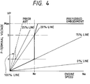
- the suppressing means suppresses the output command value to the output control device to no more than 20%.
- the suppressing means suppresses the output command value to the output control device to about 15%.
- the detecting means is inputted with a signal from an engine speed sensor monitoring a speed of the engine.
- the discriminating means includes first discriminating means for discriminating the engine self-rotating state when the engine speed exceeds the detection level during the engine starter being operated, and second discriminating means for discriminating the engine self-rotating state when the engine speed exceeds the lower limit idling speed during the engine starter being stopped.
- the increasing means comprises control means for giving the output command value to the output control device so that the output of the generator converges to a given target value, and limiting means for limiting an increasing rate of the output command value given to the output control device from the control means.
- control means is provided integral with the generator.
- control means includes a microcomputer.
- the output control device is an element which controls an exciting current of the generator in response to the output command value.
- display means is further provided which changes a display state when the engine self-rotating state is discriminated by the discriminating means.
- a generator control system for charging a battery by means of an output of an alternator driven by a vehicle engine, comprises a supply circuit for supplying the alternator with an exciting current depending on a control signal; a control circuit for outputting the control signal of the supply circuit so that a voltage of the battery converges to a given target value; a suppressing circuit for outputting a fixed control signal, the fixed control signal suppressing the output of the alternator to a small value such that no charging current to the battery is generated; a gradually exciting circuit for liming an increasing rate of the control signal given to the supply circuit; a discriminating circuit for discriminating between an engine cranking state and an engine self-rotating state based on an output from the alternator determined depending on the fixed control signal from the suppressing circuit; and a control characteristic changing circuit for giving the control signal from the suppressing circuit to the supply circuit when the engine cranking state is discriminated by the discriminating circuit, and for giving the control signal from the control circuit to the supply circuit under the limitation by the gradually exciting circuit
- the gradually exciting circuit comprises an integrating circuit for integrating an exciting current supply amount by the supply circuit, and a limiting circuit for limiting the control signal given to the supply circuit depending on an integration output from the integrating circuit.
- the discriminating circuit has a detection level which is set between an upper limit speed when the engine is cranked and a lower limit speed under idling where the engine rotates by itself, and that the discriminating circuit discriminates between the engine cranking state and the engine self-rotating state based on a comparison between the detection level and the output of the alternator.
- the suppressing circuit feeds the fixed control signal corresponding to an exciting current which can be continuously supplied to the alternator in a state where the alternator is not rotated.
- the suppressing circuit feeds the fixed control signal representing the duty of the supply circuit of no more than 20%.
- the suppressing circuit feeds the fixed control signal representing the duty of the supply circuit of about 15%.
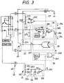
- a vehicle generator unit A includes an alternator 1 driven by an internal combustion engine and a generator (alternator) control system 2 incorporated in a casing of the alternator 1.
- the alternator 1 is in the form of a three-phase generator, and includes a field coil 11 wound around a rotor and three-phase stator coils 12, 13 and 14 wound around a stator core.
- the generator control system 2 includes a discrimination circuit 21, a drive circuit 22, a transistor 23 forming current control means, a flywheel diode 24, a complete explosion detection circuit 25, a switching circuit 26 for switching between an initial exciting control and a full exciting control, a duty detection circuit 27, a duty increasing circuit 28 for gradually increasing the duty of the transistor 23, and a NOR circuit 29.
- the discrimination circuit 21 includes voltage dividing resistors 211 and 212 for dividing a B-terminal voltage (voltage between B terminal and E terminal) to provide a voltage Vb, and a comparator 213 for comparing the voltage Vb with a reference voltage Va. When Vb ⁇ Va, an output 214 of the comparator 213 becomes Lo (low).
- the drive circuit 22 includes a resistor 221 for providing a bias voltage for driving the transistor 23.
- the complete explosion detection circuit 25 receives a generated output of the alternator 1 at one end of the stator coils.
- the detection circuit 25 includes voltage dividing resistors 251 and 252 for dividing a P-terminal voltage VP (voltage between P terminal and E terminal) to provide a voltage Vd', a diode 253 for preventing reverse-current flow, a capacitor 254 for charging based on the voltage Vd', a constant current source 255 for discharging the capacitor 254 to cause a terminal voltage Vd thereof to follow the P-terminal voltage VP, and a comparator 256 for comparing the terminal voltage Vd with a reference voltage Vc.
- Vd ⁇ Vc an output 257 of the comparator 256 becomes Hi (high).
- the high output 257 represents detection of a state of complete explosion of the engine or an engine self-rotating state where the engine rotates by itself as opposed to an engine cranking state where the engine is rotated by a starter.
- the switching circuit 26 includes a pulse generator 261 for the initial excitation and a NOR circuit 262.
- the switching circuit 26 When the output 257 of the complete explosion detection circuit 25 is Lo (detection of engine cranking state), the switching circuit 26 outputs inverted waveform of the pulse generator 261 as an output 263.
- the output 263 of the switching circuit 26 is always Lo.
- the duty detection circuit 27 is in the form of an integration circuit including a resistor 271 and a capacitor 272.
- the duty detection circuit 27 detects the mean duty of the transistor 23 by converting it to the voltage change. Specifically, when the transistor 23 is conductive (on), an F-terminal voltage (voltage between F terminal and E terminal) is at low level so that the capacitor 272 discharges via the resistor 271. On the other hand, when the transistor 23 is non-conductive (off), the F-terminal voltage is at high level so that the capacitor 272 charges via the resistor 271.
- the duty increasing circuit 28 includes a sawtooth generator 281, an operational amplifier 282, a resistor 283 and a constant current circuit 284 forming a + ⁇ circuit, and a comparator 285.
- the operational amplifier 282 is in the form of a voltage follower with a high input impedance and monitors a terminal voltage of the capacitor 272.
- the + ⁇ circuit lowers an output of the operational amplifier 282 so as to increase a duty level of the transistor 23 by + ⁇ .
- the comparator 285 compares a signal Vf lowered via the + ⁇ circuit with a sawtooth signal Ve. While Vf ⁇ Ve, an output 286 is Lo. On the other hand, while Vf>Ve, the output 286 is Hi.
- a voltage raising circuit may be added to raise the reference sawtooth signal.
- the NOR circuit 29 is inputted with the output 214 of the discrimination circuit 21, the output 263 of the switching circuit and the output 286 of the comparator 285. During a time period where all the outputs 214, 263 and 286 become Lo, an output 291 of the NOR circuit 29 becomes Hi. While the output 291 is Hi, the transistor 23 is rendered conductive (on).
- the switching circuit 26 outputs the inverted signal of the pulse generator 261 to the NOR circuit 29.
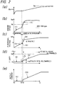
- the P-terminal voltage VP increases due to the cranking.
- the transistor 23 is operated with the low duty (15% in this embodiment) where the voltage generated by the alternator 1 is set lower than the battery voltage
- the alternator 1 provides no output to the battery and performs only the internal power generation (see (4) at (e) in Fig. 2 where the output current is zero).
- the terminal voltage Vd is less than the reference voltage Vc so that the output 257 of the complete explosion detection circuit 25 is Lo. Since the alternator 1 provides no output to the battery during cranking, the load applied to the engine can be reduced.
- the P-terminal voltage VP increases gradually.
- the 15% duty is necessary for the detection of complete explosion.
- the 15% duty is determined by the fixed control signal outputted from the pulse generator 261. This fixed control signal corresponds to an exciting current which can be continuously supplied to the alternator 1 in a state where the alternator 1 is not rotated.
- the duty of the transistor 23 is increased by + ⁇ (5% in this embodiment). Accordingly, as shown at (e) in Fig. 2, the alternator 1 starts power generation to the battery at time t2. Following this, the P-terminal voltage VP changes as shown by (8) at (c) in Fig. 2. As shown at (d) in Fig. 2, the duty of the transistor 23 is gradually increased so as to reach 100% in 7.5 seconds, and the output current of the alternator 1 is also increased corresponding to the increasing duty as shown by (10) at (e) in Fig. 2. With this arrangement, the engine load is not abruptly increased so that the engine speed rises smoothly.
- a value of + ⁇ may be selectable, for example, in the range of 5% to 10% and a duty increasing time may be selectable, for example, in the range of 5 seconds to 10 seconds.
- the duty increasing control is performed so as to start the external power generation of the alternator 1 and gradually increase the duty of the transistor.
- the vehicle generator unit C is excellent in engine starting property, particularly at the low temperatures.
- the complete explosion engine speed Nr (threshold value) which has been predetermined through experiments to be greater than the maximum cranking speed at the low temperatures, is set at step s3.
- the complete explosion engine speed Nr is set larger as the detected temperature is lower.
- the duty increasing control can be started at a proper timing depending on the ambient temperature.
- the power generation stopping period can be prevented from being too long (if too long, the battery is over-discharged).
- the duty of the transistor is changed to 20% (second set value), and then increased to 100%, for example, in 7.5 seconds.
- the second set value and the duty increasing time may be set to (first set value + 5% (cold weather) ⁇ + 10% (hot weather)) and/or (5 seconds (hot weather) ⁇ 10 seconds (cold weather)).
Landscapes
- Engineering & Computer Science (AREA)
- Power Engineering (AREA)
- Control Of Eletrric Generators (AREA)
- Control Of Charge By Means Of Generators (AREA)
- Combined Controls Of Internal Combustion Engines (AREA)
Applications Claiming Priority (3)
| Application Number | Priority Date | Filing Date | Title |
|---|---|---|---|
| JP15809595A JP3897832B2 (ja) | 1995-06-23 | 1995-06-23 | 車両用電源装置 |
| JP158095/95 | 1995-06-23 | ||
| JP15809595 | 1995-06-23 |
Publications (3)
| Publication Number | Publication Date |
|---|---|
| EP0751602A2 true EP0751602A2 (de) | 1997-01-02 |
| EP0751602A3 EP0751602A3 (de) | 1998-01-21 |
| EP0751602B1 EP0751602B1 (de) | 2001-11-07 |
Family
ID=15664201
Family Applications (1)
| Application Number | Title | Priority Date | Filing Date |
|---|---|---|---|
| EP96110074A Expired - Lifetime EP0751602B1 (de) | 1995-06-23 | 1996-06-21 | Regelungssystem für einen Fahrzeuggenerator |
Country Status (6)
| Country | Link |
|---|---|
| US (1) | US5880577A (de) |
| EP (1) | EP0751602B1 (de) |
| JP (1) | JP3897832B2 (de) |
| KR (1) | KR100277297B1 (de) |
| CN (1) | CN1049078C (de) |
| DE (1) | DE69616663T2 (de) |
Cited By (8)
| Publication number | Priority date | Publication date | Assignee | Title |
|---|---|---|---|---|
| EP0878890A1 (de) * | 1997-05-13 | 1998-11-18 | Mitsubishi Denki Kabushiki Kaisha | Generatorsteuervorrichtung für ein Fahrzeug |
| EP0881739A1 (de) * | 1997-05-26 | 1998-12-02 | Mitsubishi Denki Kabushiki Kaisha | Fahrzeuggenerator-Steuervorrichtung |
| WO1999067870A1 (de) * | 1998-06-20 | 1999-12-29 | Robert Bosch Gmbh | Spannungsregler für einen von einer brennkraftmaschine antreibbaren generator |
| EP1204200A3 (de) * | 2000-11-02 | 2003-07-30 | Denso Corporation | Fahrzeugsalternatorsteuerungsvorrichtung und -verfahren |
| EP1005131A4 (de) * | 1998-04-09 | 2004-10-20 | Mitsubishi Electric Corp | Regler für wechselspannungsgeneratoren in kraftfahrzeugen |
| WO2009062901A3 (de) * | 2007-11-16 | 2009-12-23 | Robert Bosch Gmbh | Regelung eines mit einem verbrennungsmotor verbundenen generators |
| EP2919381A4 (de) * | 2012-11-09 | 2016-06-29 | Toyota Motor Co Ltd | Generatorregler |
| CN111756296A (zh) * | 2019-03-29 | 2020-10-09 | 安川电机(中国)有限公司 | 变频器及其输出电压的控制方法、真空系统的控制方法 |
Families Citing this family (27)
| Publication number | Priority date | Publication date | Assignee | Title |
|---|---|---|---|---|
| JP3560432B2 (ja) * | 1996-12-18 | 2004-09-02 | 株式会社日立製作所 | Mosトランジスタの駆動装置 |
| DE19733221A1 (de) * | 1997-08-01 | 1999-02-04 | Bosch Gmbh Robert | Verfahren zur Regelung eines Generators |
| JP3932067B2 (ja) * | 1997-11-04 | 2007-06-20 | 株式会社デンソー | 車両用交流発電機の制御装置 |
| JP3418673B2 (ja) * | 1998-02-12 | 2003-06-23 | 株式会社日立製作所 | 車両用充電発電機の制御装置 |
| JP3742341B2 (ja) * | 1999-09-10 | 2006-02-01 | 三菱電機株式会社 | 車両用交流発電機の制御装置 |
| KR100667503B1 (ko) * | 2000-03-02 | 2007-01-10 | 주식회사 현대오토넷 | 차량의 교류 발전기 제어 장치 |
| KR100434216B1 (ko) * | 2001-12-27 | 2004-06-04 | 파츠닉(주) | 고체 전해질 콘덴서 제조용 알루미늄 호일 제조 방법 |
| US6876177B2 (en) * | 2003-02-04 | 2005-04-05 | General Motors Corporation | Load dump transient voltage controller |
| JP4481103B2 (ja) * | 2004-08-10 | 2010-06-16 | 本田技研工業株式会社 | 車両の発電制御装置、及び、その装置を搭載した車両 |
| US7240481B2 (en) * | 2005-03-10 | 2007-07-10 | Gm Global Technology Operations, Inc. | Engine load control for reduced cold start emissions |
| JP4189765B2 (ja) * | 2005-03-23 | 2008-12-03 | 株式会社デンソー | 発電制御装置 |
| JP4524663B2 (ja) * | 2005-11-02 | 2010-08-18 | 株式会社デンソー | 車両用電圧制御装置 |
| JP4682901B2 (ja) | 2006-04-04 | 2011-05-11 | 株式会社デンソー | 発電制御システム |
| JP4556926B2 (ja) * | 2006-08-07 | 2010-10-06 | 株式会社デンソー | 車両用発電制御装置 |
| JP4880520B2 (ja) * | 2007-05-28 | 2012-02-22 | ヤマハモーターエレクトロニクス株式会社 | 発電制御装置及び鞍乗型車両 |
| US20090063028A1 (en) * | 2007-08-27 | 2009-03-05 | Denso Corporation | Engine flare management system and method |
| EP2196352A4 (de) * | 2007-09-10 | 2013-05-22 | Toyota Motor Co Ltd | Fahrzeugsystemstartvorrichtung und fahrzeugsystemstartverfahren |
| US7868592B2 (en) | 2007-12-10 | 2011-01-11 | Visteon Global Technologies, Inc. | Method of automotive electrical bus management |
| CN101282103B (zh) * | 2008-04-29 | 2011-01-26 | 奇瑞汽车股份有限公司 | 一种车用发电机励磁电流控制方法及装置 |
| DE102010029967B4 (de) | 2010-06-11 | 2025-11-06 | Seg Automotive Germany Gmbh | Verfahren und Vorrichtung zum Ausgleich eines Einbruchs der Ausgangsspannung eines Kraftfahrzeuggenerators |
| JP5201196B2 (ja) * | 2010-11-12 | 2013-06-05 | 株式会社デンソー | 車両用発電制御装置 |
| JP2012125105A (ja) * | 2010-12-10 | 2012-06-28 | Denso Corp | 車両用発電制御装置 |
| DE102011105883A1 (de) * | 2011-06-28 | 2013-01-03 | Volkswagen Aktiengesellschaft | Verfahren zur Regelung eines Generators und Generatorregler |
| JP6217236B2 (ja) * | 2013-08-22 | 2017-10-25 | マツダ株式会社 | 多気筒エンジンの制御装置及び制御方法 |
| TWI545876B (zh) * | 2015-06-26 | 2016-08-11 | 財團法人工業技術研究院 | 電動車延距系統及其充電方法、發電設備與發電設備控制方法 |
| US10707788B2 (en) * | 2015-07-28 | 2020-07-07 | Ford Global Technologies, Llc | Vehicle transient voltage control |
| JP6513268B1 (ja) * | 2018-06-25 | 2019-05-15 | 三菱電機株式会社 | 発電機制御装置 |
Family Cites Families (22)
| Publication number | Priority date | Publication date | Assignee | Title |
|---|---|---|---|---|
| US4459489A (en) * | 1982-09-30 | 1984-07-10 | General Motors Corporation | Generator load response control |
| JPS59157555A (ja) * | 1983-02-28 | 1984-09-06 | Matsushita Electric Ind Co Ltd | 乾燥検知装置 |
| JPS59189498A (ja) * | 1983-04-13 | 1984-10-27 | ニツタン株式会社 | 警報装置の電源供給方式 |
| US4682044A (en) * | 1984-10-25 | 1987-07-21 | Mazda Motor Corporation | Engine idling load control means |
| JPS61171879A (ja) * | 1985-01-28 | 1986-08-02 | Daihatsu Motor Co Ltd | オルタネ−タ制御装置 |
| US4689545A (en) * | 1985-03-04 | 1987-08-25 | Mitsubishi Denki Kabushiki Kaisha | Control apparatus for vehicle battery charging generator |
| US4686446A (en) * | 1985-03-14 | 1987-08-11 | Mitsubishi Denki Kabushiki Kaisha | Power generation control apparatus for alternating current generator |
| EP0201243A3 (de) * | 1985-04-24 | 1988-01-27 | Honda Giken Kogyo Kabushiki Kaisha | Regelsystem für einen maschinengetriebenen Wechselstromgenerator |
| US4629968A (en) * | 1985-08-23 | 1986-12-16 | General Motors Corporation | Alternator load control system |
| US4636706A (en) * | 1985-09-12 | 1987-01-13 | General Motors Corporation | Generator voltage regulating system |
| JPH0638720B2 (ja) * | 1985-10-29 | 1994-05-18 | 三菱電機株式会社 | 車両用発電機の制御装置 |
| JPH0819867B2 (ja) * | 1988-10-04 | 1996-02-28 | 三菱電機株式会社 | エンジンのアイドル回転数制御装置 |
| JPH03143300A (ja) * | 1989-10-28 | 1991-06-18 | Daihatsu Motor Co Ltd | オルタネータ制御装置 |
| US5243270A (en) * | 1989-11-29 | 1993-09-07 | Nippondenso Co., Ltd. | Charging control apparatus for vehicle generators |
| US5144220A (en) * | 1989-11-30 | 1992-09-01 | Mitsubishi Denki K.K. | Vehicle ac generator control system |
| JP3004296B2 (ja) * | 1989-11-30 | 2000-01-31 | 三菱電機株式会社 | 車両用交流発電機の制御装置 |
| IT1245477B (it) * | 1991-04-22 | 1994-09-20 | Marelli Autronica | Circuito di controllo per un impianto di ricarica della batteria di unautoveicolo |
| US5225764A (en) * | 1991-11-29 | 1993-07-06 | Sgs-Thomson Microelectronics, Inc. | Voltage regulating circuitry to vary the alternator field coil drive at a rate dependent upon a rotor velocity signal |
| DE4222072C1 (de) * | 1992-07-04 | 1994-03-03 | Bosch Gmbh Robert | Einrichtung zur Regelung der Ausgangsspannung eines von einer Brennkraftmaschine angetriebenen Generators |
| US5512813A (en) * | 1992-12-24 | 1996-04-30 | Mitsubishi Denki Kabushiki Kaisha | AC generator output controlling apparatus and method |
| JPH06261466A (ja) * | 1993-03-09 | 1994-09-16 | Nippondenso Co Ltd | 車両用発電機の励磁電流制御装置 |
| JP2790779B2 (ja) * | 1994-08-22 | 1998-08-27 | 本田技研工業株式会社 | ハイブリッド車両の発電制御装置 |
-
1995
- 1995-06-23 JP JP15809595A patent/JP3897832B2/ja not_active Expired - Fee Related
-
1996
- 1996-06-21 US US08/670,755 patent/US5880577A/en not_active Expired - Lifetime
- 1996-06-21 EP EP96110074A patent/EP0751602B1/de not_active Expired - Lifetime
- 1996-06-21 DE DE69616663T patent/DE69616663T2/de not_active Expired - Lifetime
- 1996-06-23 CN CN96111077A patent/CN1049078C/zh not_active Expired - Fee Related
- 1996-06-24 KR KR1019960023297A patent/KR100277297B1/ko not_active Expired - Fee Related
Cited By (12)
| Publication number | Priority date | Publication date | Assignee | Title |
|---|---|---|---|---|
| EP0878890A1 (de) * | 1997-05-13 | 1998-11-18 | Mitsubishi Denki Kabushiki Kaisha | Generatorsteuervorrichtung für ein Fahrzeug |
| US6005372A (en) * | 1997-05-13 | 1999-12-21 | Mitsubshiki Denki Kabsuhiki Kaisha | Vehicle generator controller |
| EP0881739A1 (de) * | 1997-05-26 | 1998-12-02 | Mitsubishi Denki Kabushiki Kaisha | Fahrzeuggenerator-Steuervorrichtung |
| US5886500A (en) * | 1997-05-26 | 1999-03-23 | Mitsubishi Denki Kabushiki Kaisha | Vehicle generator controller |
| EP1005131A4 (de) * | 1998-04-09 | 2004-10-20 | Mitsubishi Electric Corp | Regler für wechselspannungsgeneratoren in kraftfahrzeugen |
| WO1999067870A1 (de) * | 1998-06-20 | 1999-12-29 | Robert Bosch Gmbh | Spannungsregler für einen von einer brennkraftmaschine antreibbaren generator |
| US6429627B1 (en) | 1998-06-20 | 2002-08-06 | Robert Bosch Gmbh | Voltage regulator for a generator drivable by an internal combustion engine |
| EP1204200A3 (de) * | 2000-11-02 | 2003-07-30 | Denso Corporation | Fahrzeugsalternatorsteuerungsvorrichtung und -verfahren |
| WO2009062901A3 (de) * | 2007-11-16 | 2009-12-23 | Robert Bosch Gmbh | Regelung eines mit einem verbrennungsmotor verbundenen generators |
| EP2919381A4 (de) * | 2012-11-09 | 2016-06-29 | Toyota Motor Co Ltd | Generatorregler |
| US9455657B2 (en) | 2012-11-09 | 2016-09-27 | Toyota Jidosha Kabushiki Kaisha | Alternator control apparatus |
| CN111756296A (zh) * | 2019-03-29 | 2020-10-09 | 安川电机(中国)有限公司 | 变频器及其输出电压的控制方法、真空系统的控制方法 |
Also Published As
| Publication number | Publication date |
|---|---|
| EP0751602A3 (de) | 1998-01-21 |
| KR970004277A (ko) | 1997-01-29 |
| DE69616663D1 (de) | 2001-12-13 |
| EP0751602B1 (de) | 2001-11-07 |
| JPH099695A (ja) | 1997-01-10 |
| CN1049078C (zh) | 2000-02-02 |
| KR100277297B1 (ko) | 2001-02-01 |
| CN1146651A (zh) | 1997-04-02 |
| DE69616663T2 (de) | 2002-08-01 |
| JP3897832B2 (ja) | 2007-03-28 |
| US5880577A (en) | 1999-03-09 |
Similar Documents
| Publication | Publication Date | Title |
|---|---|---|
| US5880577A (en) | Vehicle generator control system | |
| EP0963027B1 (de) | Steuerungssystem für einen Wechselstromgenerator eines Kraftfahrzeuges | |
| US6018199A (en) | Starter for engine equipped with motor generator | |
| US5712786A (en) | Idling speed control method and apparatus for an internal combustion engine | |
| HK1003041B (en) | Vehicle ac generator control system | |
| US6700353B2 (en) | Battery charging system and vehicle generator control system | |
| US5754030A (en) | Duty ratio control for a vehicular generator responsive to low and high power loads | |
| JP3201684B2 (ja) | バッテリレス車の始動時電装品負荷軽減制御装置 | |
| EP0438884A1 (de) | Regelgerät für einen elektrischen Generator | |
| US6215284B1 (en) | Control device of A.C. generator for vehicle | |
| EP1050945B1 (de) | Regler für den wechselstromgenerator eines fahrzeug | |
| JPWO1999053596A1 (ja) | 車両用交流発電機の制御装置 | |
| US5523672A (en) | Voltage-regulator for regulating the voltage of an alternator | |
| US4293811A (en) | Voltage regulator system for vehicle generator | |
| GB2371425A (en) | Starter/alternator control system | |
| JPH04252823A (ja) | 車両の補機制御装置 | |
| JP3004296B2 (ja) | 車両用交流発電機の制御装置 | |
| JP3656870B2 (ja) | 車両用交流発電機の電圧制御装置 | |
| JP2002031021A (ja) | エンジン発電システムおよびそのコントローラ | |
| JPH09151781A (ja) | 車両の電源制御装置 | |
| US6675642B1 (en) | Device for detecting the slip of a driving belt of a generator driven by a driving motor | |
| JP3154503B2 (ja) | 内燃機関制御装置 | |
| RU2125763C1 (ru) | Генераторная установка для автомобиля | |
| JP3087762B2 (ja) | 車両の補機制御装置 | |
| JP3329037B2 (ja) | 車両用発電機の出力電流制御装置 |
Legal Events
| Date | Code | Title | Description |
|---|---|---|---|
| PUAI | Public reference made under article 153(3) epc to a published international application that has entered the european phase |
Free format text: ORIGINAL CODE: 0009012 |
|
| AK | Designated contracting states |
Kind code of ref document: A2 Designated state(s): DE FR GB IT |
|
| RAP1 | Party data changed (applicant data changed or rights of an application transferred) |
Owner name: DENSO CORPORATION |
|
| PUAL | Search report despatched |
Free format text: ORIGINAL CODE: 0009013 |
|
| AK | Designated contracting states |
Kind code of ref document: A3 Designated state(s): DE FR GB IT |
|
| 17P | Request for examination filed |
Effective date: 19980310 |
|
| 17Q | First examination report despatched |
Effective date: 19990628 |
|
| GRAG | Despatch of communication of intention to grant |
Free format text: ORIGINAL CODE: EPIDOS AGRA |
|
| GRAG | Despatch of communication of intention to grant |
Free format text: ORIGINAL CODE: EPIDOS AGRA |
|
| GRAG | Despatch of communication of intention to grant |
Free format text: ORIGINAL CODE: EPIDOS AGRA |
|
| GRAH | Despatch of communication of intention to grant a patent |
Free format text: ORIGINAL CODE: EPIDOS IGRA |
|
| RIN1 | Information on inventor provided before grant (corrected) |
Inventor name: TANAKA, KOUZI Inventor name: AOYAMA, TOORU |
|
| GRAH | Despatch of communication of intention to grant a patent |
Free format text: ORIGINAL CODE: EPIDOS IGRA |
|
| GRAA | (expected) grant |
Free format text: ORIGINAL CODE: 0009210 |
|
| AK | Designated contracting states |
Kind code of ref document: B1 Designated state(s): DE FR GB IT |
|
| REF | Corresponds to: |
Ref document number: 69616663 Country of ref document: DE Date of ref document: 20011213 |
|
| REG | Reference to a national code |
Ref country code: GB Ref legal event code: IF02 |
|
| PLBE | No opposition filed within time limit |
Free format text: ORIGINAL CODE: 0009261 |
|
| STAA | Information on the status of an ep patent application or granted ep patent |
Free format text: STATUS: NO OPPOSITION FILED WITHIN TIME LIMIT |
|
| 26N | No opposition filed | ||
| PGFP | Annual fee paid to national office [announced via postgrant information from national office to epo] |
Ref country code: DE Payment date: 20120613 Year of fee payment: 17 |
|
| PGFP | Annual fee paid to national office [announced via postgrant information from national office to epo] |
Ref country code: FR Payment date: 20120619 Year of fee payment: 17 Ref country code: GB Payment date: 20120620 Year of fee payment: 17 |
|
| PGFP | Annual fee paid to national office [announced via postgrant information from national office to epo] |
Ref country code: IT Payment date: 20120620 Year of fee payment: 17 |
|
| GBPC | Gb: european patent ceased through non-payment of renewal fee |
Effective date: 20130621 |
|
| REG | Reference to a national code |
Ref country code: DE Ref legal event code: R119 Ref document number: 69616663 Country of ref document: DE Effective date: 20140101 |
|
| REG | Reference to a national code |
Ref country code: FR Ref legal event code: ST Effective date: 20140228 |
|
| PG25 | Lapsed in a contracting state [announced via postgrant information from national office to epo] |
Ref country code: GB Free format text: LAPSE BECAUSE OF NON-PAYMENT OF DUE FEES Effective date: 20130621 Ref country code: DE Free format text: LAPSE BECAUSE OF NON-PAYMENT OF DUE FEES Effective date: 20140101 |
|
| PG25 | Lapsed in a contracting state [announced via postgrant information from national office to epo] |
Ref country code: FR Free format text: LAPSE BECAUSE OF NON-PAYMENT OF DUE FEES Effective date: 20130701 Ref country code: IT Free format text: LAPSE BECAUSE OF NON-PAYMENT OF DUE FEES Effective date: 20130621 |