US5712786A - Idling speed control method and apparatus for an internal combustion engine - Google Patents
Idling speed control method and apparatus for an internal combustion engine Download PDFInfo
- Publication number
- US5712786A US5712786A US08/321,606 US32160694A US5712786A US 5712786 A US5712786 A US 5712786A US 32160694 A US32160694 A US 32160694A US 5712786 A US5712786 A US 5712786A
- Authority
- US
- United States
- Prior art keywords
- alternator
- value
- current
- battery
- engine
- Prior art date
- Legal status (The legal status is an assumption and is not a legal conclusion. Google has not performed a legal analysis and makes no representation as to the accuracy of the status listed.)
- Expired - Fee Related
Links
Images


Classifications
-
- F—MECHANICAL ENGINEERING; LIGHTING; HEATING; WEAPONS; BLASTING
- F02—COMBUSTION ENGINES; HOT-GAS OR COMBUSTION-PRODUCT ENGINE PLANTS
- F02D—CONTROLLING COMBUSTION ENGINES
- F02D41/00—Electrical control of supply of combustible mixture or its constituents
- F02D41/02—Circuit arrangements for generating control signals
- F02D41/04—Introducing corrections for particular operating conditions
- F02D41/08—Introducing corrections for particular operating conditions for idling
- F02D41/083—Introducing corrections for particular operating conditions for idling taking into account engine load variation, e.g. air-conditionning
-
- F—MECHANICAL ENGINEERING; LIGHTING; HEATING; WEAPONS; BLASTING
- F02—COMBUSTION ENGINES; HOT-GAS OR COMBUSTION-PRODUCT ENGINE PLANTS
- F02D—CONTROLLING COMBUSTION ENGINES
- F02D31/00—Use of speed-sensing governors to control combustion engines, not otherwise provided for
- F02D31/001—Electric control of rotation speed
- F02D31/002—Electric control of rotation speed controlling air supply
- F02D31/003—Electric control of rotation speed controlling air supply for idle speed control
- F02D31/005—Electric control of rotation speed controlling air supply for idle speed control by controlling a throttle by-pass
-
- F—MECHANICAL ENGINEERING; LIGHTING; HEATING; WEAPONS; BLASTING
- F02—COMBUSTION ENGINES; HOT-GAS OR COMBUSTION-PRODUCT ENGINE PLANTS
- F02D—CONTROLLING COMBUSTION ENGINES
- F02D41/00—Electrical control of supply of combustible mixture or its constituents
- F02D41/20—Output circuits, e.g. for controlling currents in command coils
-
- F—MECHANICAL ENGINEERING; LIGHTING; HEATING; WEAPONS; BLASTING
- F02—COMBUSTION ENGINES; HOT-GAS OR COMBUSTION-PRODUCT ENGINE PLANTS
- F02D—CONTROLLING COMBUSTION ENGINES
- F02D11/00—Arrangements for, or adaptations to, non-automatic engine control initiation means, e.g. operator initiated
- F02D11/06—Arrangements for, or adaptations to, non-automatic engine control initiation means, e.g. operator initiated characterised by non-mechanical control linkages, e.g. fluid control linkages or by control linkages with power drive or assistance
- F02D11/10—Arrangements for, or adaptations to, non-automatic engine control initiation means, e.g. operator initiated characterised by non-mechanical control linkages, e.g. fluid control linkages or by control linkages with power drive or assistance of the electric type
- F02D2011/101—Arrangements for, or adaptations to, non-automatic engine control initiation means, e.g. operator initiated characterised by non-mechanical control linkages, e.g. fluid control linkages or by control linkages with power drive or assistance of the electric type characterised by the means for actuating the throttles
- F02D2011/102—Arrangements for, or adaptations to, non-automatic engine control initiation means, e.g. operator initiated characterised by non-mechanical control linkages, e.g. fluid control linkages or by control linkages with power drive or assistance of the electric type characterised by the means for actuating the throttles at least one throttle being moved only by an electric actuator
-
- F—MECHANICAL ENGINEERING; LIGHTING; HEATING; WEAPONS; BLASTING
- F02—COMBUSTION ENGINES; HOT-GAS OR COMBUSTION-PRODUCT ENGINE PLANTS
- F02D—CONTROLLING COMBUSTION ENGINES
- F02D41/00—Electrical control of supply of combustible mixture or its constituents
- F02D41/20—Output circuits, e.g. for controlling currents in command coils
- F02D2041/202—Output circuits, e.g. for controlling currents in command coils characterised by the control of the circuit
- F02D2041/2024—Output circuits, e.g. for controlling currents in command coils characterised by the control of the circuit the control switching a load after time-on and time-off pulses
- F02D2041/2027—Control of the current by pulse width modulation or duty cycle control
-
- F—MECHANICAL ENGINEERING; LIGHTING; HEATING; WEAPONS; BLASTING
- F02—COMBUSTION ENGINES; HOT-GAS OR COMBUSTION-PRODUCT ENGINE PLANTS
- F02D—CONTROLLING COMBUSTION ENGINES
- F02D41/00—Electrical control of supply of combustible mixture or its constituents
- F02D41/20—Output circuits, e.g. for controlling currents in command coils
- F02D2041/202—Output circuits, e.g. for controlling currents in command coils characterised by the control of the circuit
- F02D2041/2058—Output circuits, e.g. for controlling currents in command coils characterised by the control of the circuit using information of the actual current value
-
- F—MECHANICAL ENGINEERING; LIGHTING; HEATING; WEAPONS; BLASTING
- F02—COMBUSTION ENGINES; HOT-GAS OR COMBUSTION-PRODUCT ENGINE PLANTS
- F02D—CONTROLLING COMBUSTION ENGINES
- F02D2200/00—Input parameters for engine control
- F02D2200/50—Input parameters for engine control said parameters being related to the vehicle or its components
- F02D2200/503—Battery correction, i.e. corrections as a function of the state of the battery, its output or its type
-
- F—MECHANICAL ENGINEERING; LIGHTING; HEATING; WEAPONS; BLASTING
- F02—COMBUSTION ENGINES; HOT-GAS OR COMBUSTION-PRODUCT ENGINE PLANTS
- F02D—CONTROLLING COMBUSTION ENGINES
- F02D9/00—Controlling engines by throttling air or fuel-and-air induction conduits or exhaust conduits
- F02D9/08—Throttle valves specially adapted therefor; Arrangements of such valves in conduits
- F02D9/10—Throttle valves specially adapted therefor; Arrangements of such valves in conduits having pivotally-mounted flaps
- F02D9/1035—Details of the valve housing
- F02D9/1055—Details of the valve housing having a fluid by-pass
-
- Y—GENERAL TAGGING OF NEW TECHNOLOGICAL DEVELOPMENTS; GENERAL TAGGING OF CROSS-SECTIONAL TECHNOLOGIES SPANNING OVER SEVERAL SECTIONS OF THE IPC; TECHNICAL SUBJECTS COVERED BY FORMER USPC CROSS-REFERENCE ART COLLECTIONS [XRACs] AND DIGESTS
- Y02—TECHNOLOGIES OR APPLICATIONS FOR MITIGATION OR ADAPTATION AGAINST CLIMATE CHANGE
- Y02T—CLIMATE CHANGE MITIGATION TECHNOLOGIES RELATED TO TRANSPORTATION
- Y02T10/00—Road transport of goods or passengers
- Y02T10/10—Internal combustion engine [ICE] based vehicles
- Y02T10/40—Engine management systems
Definitions
- the present invention relates to an idling speed control method and apparatus for an internal combustion engine, and more particularly, to a method and an apparatus capable of stabilizing the idling speed control despite a sudden increase of electric loads during idle operation.
- a short-intake state lasts such that the engine speed is lower than the target speed.
- An idle-cylinder engine is a generally-known engine which is designed so that its output can be lowered to improve the fuel efficiency of the engine by laying half of cylinders, e.g., two cylinders of a four-cylinder engine, idle during low-speed operation.
- the aforesaid reduction of the speed is accelerated when the electric load is applied.
- the intake pipe capacity for each of the acting cylinders is larger in the idle operation than in full-cylinder operation. Even when the intake by-pass valve is opened in order to increase the air intake suddenly, therefore, the air intake actually does not do so.
- the current value can be restricted to the no-load level by restraining the generated current from suddenly increasing from a no-load state.
- a control device of a type such that the presence/absence of an electric load is recognized from the generated current value, the size of the load cannot be identified by the current value.
- the air intake rate cannot be previously stepped up in accordance with the size of the electric load.
- FIGS. 9A to 9D show an example of idling stability obtained when an electric load is applied to an idle-cylinder engine according to the conventional idling speed control method.
- an engine control unit gradually increases the by-pass valve opening in accordance with the generated current value (as indicated by arrow B of FIG. 9B) while restraining the current value from increasing suddenly (FIG. 9C).
- the by-pass valve opening is not increased (during period A of FIG. 9B).
- the by-pass valve opening increases bit by bit in accordance with the generated current value of the alternator, so that the increase of the air intake is very slow (as indicated by arrow B in FIG. 9B).
- the reduction of the engine speed according to the conventional control method can be lessened (FIG. 9A) only by restraining the power generation rate of the alternator for a longer period of time. If this is done, however, the possibility of over-discharge of a battery increases (during period C of FIG. 9D).
- the object of the present invention is to provide an idling speed control method and apparatus for an internal combustion engine, which ensure high idling stability against fluctuations of electric loads, and in which operation of some of cylinders of the engine can be interrupted during idle operation, and the target idling speed can be set at a lower value, so that the fuel efficiency can be improved.
- an idling speed control method and apparatus in which the field current of an alternator is turned on and off to control the power generation rate of the alternator in accordance with the terminal voltage of a battery, and the air intake of an internal combustion engine is increased and decreased to keep the engine speed at a target speed during an idle operation of the engine such that the field current of the alternator is gradually increased toward a field current value corresponding to an electric load when the electric load is increased suddenly.
- the state of the battery is detected, a battery current consumption value is estimated from the detected battery state, a generated current value of the alternator is detected, the value of an electric load current to be outputted from the alternator is obtained in accordance with the estimated battery current consumption value and the generated current value of the alternator, preferably in accordance with the sum of the battery current consumption value and the generated current value of the alternator, and the air intake is increased in accordance with the electric load current value.
- the electric load current value to be outputted from the alternator is quickly obtained from a drop of the battery voltage, etc., and the air intake is increased in accordance with the obtained current value.
- the load torque (power generation rate) and the engine output torque are balanced with each other to keep the engine speed for the idle operation constant.
- the air intake is increased when a set value is exceeded by the obtained electric load current value, and the increment of the air intake is set in accordance with the electric load current value.
- the air intake is increased when a first set value is exceeded by the obtained electric load current value, the increment of the air intake being set in accordance with the difference between the electric load current value and a second set value which is smaller than the first set value.
- FIG. 1 is a schematic view of an idling speed control apparatus according to the present invention
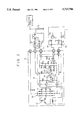
- FIG. 2 is a circuit diagram showing one embodiment of a charging circuit of an alternator of FIG. 1;
- FIG. 3 is a flowchart showing a control sequence for field terminal signal level counting and G terminal duty drive for the alternator of FIG. 2;
- FIG. 4 is a part of a flowchart showing a control sequence for the calculation of the field duty ratio, generated current value, and electric load current value, determination of the electric loads, and G terminal duty drive for the alternator of FIG. 2;
- FIG. 5 is another part of the flowchart subsequent to the control sequence of FIG. 4;
- FIG. 6 is the remainder of the flowchart subsequent to the control sequence of FIG. 5;
- FIG. 7 is a flowchart showing a control sequence for ISC electric load correction
- FIGS. 8A to 8E are time-based state diagrams for idle operation of an engine to which an idling speed control method according to the invention is applied, in which FIG. 8A shows the change of the battery voltage with time, FIG. 8B shows the change of the engine speed with time, FIG. 8C shows the change of the opening of an idling speed control (ISC) valve with time, FIG. 8D shows the change of the electric load current value with time, and FIG. 8E shows the change of the generated current value with time; and
- ISC idling speed control
- FIGS. 9A to 9D are time-based state diagrams for idle operation of an engine to which a conventional idling speed control method is applied, in which FIG. 9A shows the change of the engine speed with time, FIG. 9B shows the change of the opening of an ISC valve with time, FIG. 9C shows the change of the generated current value with time, and FIG. 9D shows the change of the battery voltage with time.
- FIG. 1 shows an outline of an idling speed control apparatus for an engine according to the present invention.
- An intake pipe 2 of the engine 1 is provided, in the middle thereof, with a throttle valve 3 and a by-pass passage 4 for by-passing the valve 3.
- the by-pass passage 4 is provided with an ISC valve (air intake control valve) 5 for idling speed control (ISC).
- ISC valve 5 is driven by means of a stepping motor to open and close the by-pass passage 4, thereby controlling the intake of air which is sucked into the engine 1 in an idling mode.
- Numeral 8 denotes an alternator, whose rotor is rotated by means of the engine 1 with the aid of a belt (not shown).
- the engine 1 to which the present invention is applied may be the aforementioned idle-cylinder engine or an engine of a type such that vertical laminar eddies of an air-fuel mixture and air are formed in cylinders to undergo lean combustion.
- the air intake control valve 5 is not limited to the aforesaid ISC valve, and may alternatively be of a type such that it can force a throttle valve in the middle of an intake pipe to open and close without regard to artificial operation, for example.
- An engine control unit 7 is used to effect the control of the output current of the alternator 8, idling speed control which is based on the adjustment of the opening of the ISC valve 5 in accordance with the engine load, and the like.
- the unit 7 is connected electrically, on the input side thereof, with a neutral switch of a transmission, electric load switch, vehicle velocity sensor, etc., as well as a water temperature sensor, crank angle sensor, air conditioner switch, power steering fluid pressure switch, ignition switch ST, idling switch, etc.
- the unit 7 is supplied with engine operation mode signals from these sensors and switches.
- the input of the unit 7 is also connected electrically with FR and G terminals of the alternator 8. Thus, the unit 7 receives a signal from the FR terminal, and controls conduction between the G terminal and the ground, thereby controlling the output current of the alternator 8.
- FIG. 2 shows a charging system for the alternator 8 of FIG. 1.
- the alternator 8 contains therein a rectifier circuit 10, auxiliary diodes 11, voltage regulator 12, stator coil 13, and field coil 14, and has five terminals, i.e., B, L, S, G and FR terminals.
- Output terminals of the stator coil 13 are connected to the B terminal via the rectifier circuit 10, and are also connected to a T terminal of the voltage regulator 12 and one end of the field coil 14 through their corresponding auxiliary diodes 11.
- the other end of the field coil 14 is connected to an F terminal of the voltage regulator 12.
- the voltage regulator 12 is composed of an IC circuit of a battery voltage detection type in which voltage detection is based on a battery, and has seven terminals, i.e., F, E, L, S, G and FR terminals plus the T terminal, and three transistors Tr1, Tr2 and Tr3.
- the L terminal is connected to the E terminal via the T terminal and a series circuit of resistors R1 and R2, while the S terminal is connected to the E terminal through a series circuit of resistors R5, R6 and R7.
- the collector of the transistor Tr2 is connected to the L terminal through a resistor R3, and the emitter thereof to the E terminal.
- the base of the transistor Tr2 is connected to the junction of the resistors R1 and R2 through a Zener diode ZD1 and a diode D1, to the E terminal through a resistor R4, and to the collector through a capacitor C1.
- the junction of the Zener diode ZD1 and the diode D1 is connected to the junction of the resistors R5 and R6 through a diode D2.
- the collector of the power transistor Tr1 is connected to the F terminal, to the T terminal through a flywheel diode D F , and to the FR terminal through a diode D3.
- the base and emitter of the power resistor R1 are connected to the collector of the transistor Tr2 and the E terminal, respectively.
- the transistor Tr3 has its collector connected to the junction of the resistors R6 and R7, its emitter to the E terminal, and its base to the G terminal through a resistor R8.
- the G terminal is connected to the L terminal through a resistor R9.
- the F terminal is connected to the FR terminal via the diode D3, while the E terminal is Grounded together with an earth terminal of the rectifier circuit 10.
- the B, L and S terminals of the alternator 8 are connected to a positive terminal of a battery 15 and various electric loads (not shown), to the positive terminal of the battery 15 through a parallel circuit of a charge lamp 16 and a resistor R10 and an ignition switch 17, and directly to the positive terminal of the battery 15, respectively.
- the G and FR terminals of the alternator 8 are connected to terminals 7a and 7b of the engine control unit 7, respectively.
- the terminal 7a of the engine control unit 7 is connected to the collector of a transistor Tr4 through a resistor R11.
- the transistor Tr4 has its emitter grounded and its base connected to a control circuit (not shown).
- the terminal 7b is connected to the control circuit through a diode D4 and a resistor R12, and the junction of the diode D4 and the resistor R12 is connected to a power source +V through a resistor R13.
- a field current is supplied from the auxiliary diodes 11 to the field coil 14 to continue the power generation, and a generated current is delivered from the rectifier circuit 10 to the B terminal, and supplied to the electric loads, such as headlights. Also, the battery 15 is charged.
- the transistors Tr2 and Tr1 are turned on and off, respectively. Thereupon, the field current of the field coil 14 of the alternator 8 goes on flowing through the flywheel diode D F due to the presence of an inductance component of the coil 14, and the output current of the alternator 8 is reduced by a margin corresponding to the field current which flows through the coil 14.
- the output current of the alternator 8 As the output current of the alternator 8 is reduced in this manner, the output voltage increases slightly. Since the field current is reduced, however, the output voltage decreases gradually.
- the transistor Tr2 When the predetermined voltage is reached, the transistor Tr2 is turned off, while the power transistor Tr1 is turned on again. As these processes of operation are repeated, the output voltage is adjusted to the level of the predetermined voltage. Thus, the power transistor Tr1 are repeatedly turned on and off.
- the intensity of the output current of the alternator 8 is settled depending on the proportion of the on-time of the power transistor Tr1.
- the voltage at the FR terminal of the alternator 8 goes low when the power transistor Tr1 is turned on, and goes high when the transistor Tr1 is turned off. Accordingly, the output current of the alternator 8 can be detected by calculating the proportion of the period during which the FR terminal is on the low level. More specifically, the conduction state (on or off state) of the field coil 14 is delivered from the FR terminal of the alternator 8 to the engine control unit 7. In response to a signal for the on or off state, the unit 7 detects the output current of the alternator 8. In accordance with the detected output current, the unit 7 drives the ISC valve 5 to control the intake of air sucked into the engine 1.
- the engine control unit 7 subjects the conduction between the G terminal of the alternator 8 and the ground to duty control, thereby controlling the output current of the alternator 8.
- the unit 7 turns on and off the transistor Tr4 to subject the conduction between the G terminal of the alternator 8 and the ground to duty control, thereby limiting the output current of the alternator 8.
- the off duty of the G terminal is controlled so as to be equal to the on duty of the power transistor Tr1 of the voltage regulator 12.
- the power transistor Tr1 When the voltage at the S terminal of the alternator 8 reaches a first predetermined voltage (e.g., 14.4 volts), the power transistor Tr1 is turned off, so that the field current is cut off to stop the power generation. Thus, the output voltage of the alternator 8 is adjusted to the aforesaid predetermined voltage.
- a first predetermined voltage e.g. 14.4 volts
- the transistor Tr4 When the transistor Tr4 is turned on so that the G terminal of the alternator 8 is shorted to the ground (duty ratio Dg is set to be 0%), the transistor Tr1 is made to be normally off. In this case, the power transistor Tr1 is turned on when the S terminal voltage of the alternator 8 reaches a second predetermined voltage (e.g., 12.3 volts).
- a second predetermined voltage e.g., 12.3 volts
- the interruption of the power generation (cut-off of field current) of the alternator 8 can be controlled externally, and the power generation rate can be controlled by setting the proportion of the period during which the G terminal is not grounded, that is, the G terminal duty ratio Dg, at a suitable value. If the output voltage of the alternator 8 drops to the aforesaid predetermined voltage, then it is lower than the voltage of the charged battery 15, so that hardly any current is supplied from the alternator 8.
- any electric loads e.g., the headlights
- the current consumption increases suddenly (as indicated by arrow A in FIG. 8D).
- the battery voltage instantaneously drops before the power generation rate increases accompanying the sudden increase of the load current (FIG. 8A).
- the alternator 8 operates so as to increase the power generation rate (FIG. 8E).
- the battery voltage responds earliest to the sudden increase of the electric loads.
- the drop of the battery voltage depends on the size of the electric loads. In other words, the electric loads require a current value higher than the power generation rate of the alternator 8 when the battery voltage is lowered.
- the engine control unit 7 detects the battery voltage value, estimates a battery current consumption value from the difference between the detected voltage value and a predetermined value set beforehand, and obtains an electric load current value to be delivered from the alternator 8 according to the sum of the estimated current consumption value and the generated current value of the alternator 8.
- the power generation rate of the alternator 8 can be obtained from the on duty of the field coil 14 and the engine speed. Based on the electric load current value thus obtained, the presence/absence of the electric loads is determined, the opening of the ISC valve 5 is settled, and the valve 5 is controlled to increase the intake of air which flows through the by-pass passage 4 (FIG. 8C). Thus, when the predicted load current value exceeds a predetermined value, the ISC valve 5 is opened to increase the air intake quickly.
- the engine control unit 7 quickly detects this load application from the drop of the battery voltage, and causes the ISC valve 5 to open wide. On the other hand, the unit 7 increases the generated current value of the alternator 8 at a rate corresponding to the increase of the air intake (FIG. 8E), thereby equilibrating the load torque (power generation rate) and output torque (air intake). As a result, the reduction of the engine speed is lessened, so that the idle operation can enjoy high stability against fluctuations of the electric loads (FIG. 8B).
- Step S1 the engine control unit 7 causes interruption with every period of, e.g., 0.25 ms by timer interruption (Step S1), and determines whether or not the signal level of the field terminal FR is low (Step S2).
- This routine may be executed by interruption based on crank pulses which are generated with every predetermined crank angle of the engine, in place of the timer interruption.
- Step S3 a count value FR of an FR counter is incremented by 1 (Step S3), whereupon the program advances to Step S4. If the decision in Step S2 is No, the program advances directly to Step S4. In Step S4, a count value G in a G counter is decremented by 1. Then, whether or not the value in the G counter is 0 or less is determined in Step S5. If the counter value G is 0 or less, the G terminal is set on the low level (L-level) or grounded, whereupon the routine concerned is finished (Step S6). If the value G is greater than 0, the G terminal is set on the high level (H-level) or released, whereupon the routine concerned is finished (Step S7).
- the transistor Tr3 (FIG. 2) is normally off when the G terminal is on the L-level.
- the voltage at the S terminal reaches the aforesaid second predetermined voltage
- the power transistor Tr1 is turned off, and the output voltage is adjusted to this predetermined voltage.
- the G terminal is on the H-level
- the transistor Tr3 is normally on.
- the S terminal voltage reaches the aforesaid first predetermined voltage
- the power transistor Tr1 is turned off, and the output voltage is adjusted to this predetermined voltage.
- Step S10 of FIG. 4 interruption is made in synchronism with the crank angle (Step S10 of FIG. 4), an FR duty ratio Dfold for the preceding cycle is loaded into a memory (Step S11), the stroke period of a crank shaft is read (Step S12), an FR duty ratio Dfr for the present cycle is calculated in accordance with the counter value FR obtained in Step S3, and the counter value FR is cleared to be 0 (Step S14).
- a generated current Ialt of the alternator 8 is obtained from the calculated FR duty ratio Dfr and an engine speed Ne with reference to a map (Step S15 of FIG. 5).
- the map values corresponding to the duty ratio Dfr calculated in Step S13 and the detected engine speed Ne are read out, and the generated current value Ialt is obtained from these map values by the interpolation method.
- An electric load current value Iel is calculated according to the following equation based on the alternator generated current value Ialt (Step S16): ##EQU1## where Kamp is a coefficient of conversion from the battery voltage value to a current value, Xvb is a reference voltage value (e.g., 14 volts) of the battery, and Vb is a detected battery voltage value. If the detected battery voltage value Vb is greater than the reference voltage value Xvb, however, the electric load current value Iel is obtained according to the following equation:
- Step S17 After the electric load current value Iel is calculated, it is determined whether or not the engine is in a predetermined operation mode which allows low-speed rotation for idling (Step S17). It is concluded that the engine is in this predetermined operation mode when all of the following conditions (1) to (4) are fulfilled.
- XTWOIC is adjusted to a value which is equivalent to an ISC feedback control inhibiting time (e.g., 3 to 10 seconds) after the start of the engine operation
- XWTFB is adjusted to the value of the engine cooling water temperature which allows the start of fuel supply feedback control (based on the oxygen concentration of exhaust gas).
- Step S18 When the engine is in the predetermined operation mode, it is determined whether or not the electric load current value Iel is greater than a no-load reference current value Xel1 (e.g., 10 amperes) (Step S18). If the former is greater than the latter (Iel>Xel1), an electric load flag is turned on (Step S19). If the decision in either Step S17 or S18 is No, the electric load flag is turned off (Step S20), whereupon the program advances to Step S21 in FIG. 6.
- a target FR duty ratio Dfrobj is calculated according to the following equation:
- the target FR duty ratio Dfrobj calculated in Step S21 is adjusted to a smaller one of two values, the FR duty ratio Dfr obtained by the execution of the routine for the present cycle and the sum of an FR duty ratio Dfrold obtained by the execution of the routine for the preceding cycle and an allowable increment Xfrup of the FR duty.
- the target FR duty ratio Dfrobj is prevented from increasing suddenly.
- Step S22 whether or not the engine is in an idling region is determined under the following condition:
- Step S22 If it is concluded in Step S22 that the engine is in the idling region, the program advances to Step S23. If the engine is not in the idling region, the program advances to Step S24, whereupon the G terminal duty ratio Dg is calculated for each step.
- Step S23 the G terminal duty ratio Dg is calculated according to the following equation:
- Xgdb is an infinitesimal dead-zone value.
- the power generation rate of the alternator 8 is continually subjected to duty control based on the G terminal duty ratio Dg.
- Step S24 the G terminal duty ratio Dg is calculated according to the following equation:
- Step S25 the calculated G terminal duty ratio Dg is reduced to the G counter value according to the following equation, whereupon the routine concerned is finished:
- the initial value of the aforesaid counter value G obtained in Step S4 is adjusted to a value corresponding to the power generation rate of 60% when the G terminal duty ratio Dg is 60%, for example.
- the routine of FIG. 3 is executed with every 0.25 ms, the G terminal voltage level is controlled, so that the power generation rate is adjusted to 60%.
- the value of the target FR duty ratio Dfrobj never increases suddenly. Thus, even if the FR duty ratio Dfr for the present cycle increases suddenly (Dfr>Dfrold+Xgdb), the target FR duty ratio Dfrobj cannot be set at a value greater than the sum of the value Dfrold for the preceding cycle and the increment Xfrup.
- the sum of the target FR duty ratio Dfrobj and the dead-zone value Xgdb is used as the G terminal duty ratio Dg for the present cycle. Thus, the G terminal duty ratio Dg increases slowly, so that the alternator power generation rate increases gently.
- Step S30 of FIG. 7 the ISC routine is executed with every predetermined period (of e.g., 0.25 ms) in response to interruption, and ISC electric load correction is executed.
- the following is a description of steps of procedure for the correction.
- a basic opening Pbase of the ISC valve 5 is calculated (Step S31).
- the basic opening Pbase is calculated according to a map g WT! with use of the engine cooling water temperature as a parameter, for example.
- a learning value ⁇ Plearn is added to the basic opening Pbase to Calculate a target opening Pobj of the ISC valve 5 (Step S32).
- the target opening Pobj is represented by the number of steps of the stepping motor as a valve opening controlled variable of the ISC valve 5. Alternatively, however, it may be represented in terms of the movement of the stem of the valve 5 or the like.
- the learning value ⁇ Plearn is used to modify the change of the relationship between the ISC valve opening and the by-pass air intake rate which is attributable to lowering of the engine performance, such as clogging of the ISC valve 5, or change of the atmospheric conditions.
- the value ⁇ Plearn is obtained as the time-based average of variations of the set basic opening Pbase, for example, on the basis of learning during the engine operation.
- the idling speed of the engine can be kept at its target value, which corresponds to the engine cooling water temperature, by the use of the learning value ⁇ Plearn.
- Step S33 it is determined whether or not the electric load flag is on. If the electric load flag is on, an electric load correction is added to the target opening Pobj of the ISC valve 5 calculated in Step S32, according to the following equation, thereby correcting target opening Pobj (Step S34), whereupon the routine concerned is finished.
- Xel2 is a reference current value for electric load correction, which is set to be smaller than the aforesaid no-load reference current value Xel1 (Xel2 ⁇ Xel1).
- the value Kel is a conversion factor for conversion from the current value to the valve opening value.
- FIG. 8 show, by way of example, response characteristics obtained in the idling mode of the idle-cylinder engine to which the present invention is applied.
- the electric load current value calculated in Step S16 can be changed suddenly, as indicated by arrow A in FIG. 8D, so that the responsiveness of the electric load decision is improved.
- the opening of the ISC valve is stepped up (as indicated by arrow B in FIG. 8C), and the power generation inhibiting period of the alternator basically may be as short as an intake response delay time (period C of FIG. 8B).
- the battery discharge period (period D of FIG. 8A) is shortened, so that the period during which the engine speed is lowered is shortened (FIG. 8B). In this manner, the response characteristic of the idling speed control is improved considerably.
- the electric load correction reference current value Xel2 is set to be smaller than the no-load reference current value Xel1, and a certain dead zone is provided for the detection of the generation of the electric load. While this small reference current value Xel2 is used to ensure the detection of the generation of the electric load, the other relatively small decision value Xel1 is used to obtain the required increment of the air intake securely after the generation of the electric load is detected. For simplicity, however, these decision values may be equalized.
- the generation of the electric load can be detected by using the result of comparison between the electric load current value Iel and its reference value.
- the result of comparison between the generated current value Ialt and its reference value may be used instead.
Landscapes
- Engineering & Computer Science (AREA)
- Chemical & Material Sciences (AREA)
- Combustion & Propulsion (AREA)
- Mechanical Engineering (AREA)
- General Engineering & Computer Science (AREA)
- Electrical Control Of Air Or Fuel Supplied To Internal-Combustion Engine (AREA)
- Control Of Charge By Means Of Generators (AREA)
- Control Of Vehicle Engines Or Engines For Specific Uses (AREA)
- Combined Controls Of Internal Combustion Engines (AREA)
Abstract
Description
Dfr=Counter value FR×0.25 ms/stroke period.
Ialt=f Ne, Dfr!.
Electric load current value Iel=Ialt.
Dfrobj=min{Dfr, Dfrold+Xfrup}.
N≦Xneid,
Dg=Dfrobj+Xgdb,
Dg=100%.
Counter value G=Dg×stroke period/0.25 ms.
Target by-pass valve opening Pobj=Phase+ΔPlearn.
Electric load correction value=Kel·(Iel-Xel2),
Target by-pass valve opening Pobj=Pobj+Kel·(Iel-Xel2).
Claims (6)
Applications Claiming Priority (2)
| Application Number | Priority Date | Filing Date | Title |
|---|---|---|---|
| JP5-254505 | 1993-10-12 | ||
| JP5254505A JPH07103010A (en) | 1993-10-12 | 1993-10-12 | Method of controlling idle rotation speed of engine |
Publications (1)
| Publication Number | Publication Date |
|---|---|
| US5712786A true US5712786A (en) | 1998-01-27 |
Family
ID=17265992
Family Applications (1)
| Application Number | Title | Priority Date | Filing Date |
|---|---|---|---|
| US08/321,606 Expired - Fee Related US5712786A (en) | 1993-10-12 | 1994-10-12 | Idling speed control method and apparatus for an internal combustion engine |
Country Status (2)
| Country | Link |
|---|---|
| US (1) | US5712786A (en) |
| JP (1) | JPH07103010A (en) |
Cited By (40)
| Publication number | Priority date | Publication date | Assignee | Title |
|---|---|---|---|---|
| US5947082A (en) * | 1997-11-05 | 1999-09-07 | Ford Global Technologies, Inc. | Idle air bypass valve silencer |
| US5978719A (en) * | 1996-04-10 | 1999-11-02 | Honda Giken Kogyo Kabushiki Kaisha | Control system for hybrid vehicles |
| US6018200A (en) * | 1994-09-14 | 2000-01-25 | Coleman Powermate, Inc. | Load demand throttle control for portable generator and other applications |
| US6118186A (en) * | 1994-09-14 | 2000-09-12 | Coleman Powermate, Inc. | Throttle control for small engines and other applications |
| US6184661B1 (en) | 1999-06-22 | 2001-02-06 | C. E. Niehoff & Co. | Regulator with alternator output current and input drive power control |
| EP1091481A2 (en) * | 1999-10-09 | 2001-04-11 | Bayerische Motoren Werke Aktiengesellschaft | A generator system |
| US6275012B1 (en) | 1999-12-16 | 2001-08-14 | C.E. Niehoff & Co. | Alternator with regulation of multiple voltage outputs |
| US6274944B1 (en) | 2000-01-06 | 2001-08-14 | Detroit Diesel Corporation | Method for engine control |
| US20010030843A1 (en) * | 2000-03-29 | 2001-10-18 | Autonetworks Technologies, Ltd. | Power supply system by use of vehicle |
| US6467442B2 (en) | 1999-10-18 | 2002-10-22 | Ford Global Technologies, Inc. | Direct injection variable valve timing engine control system and method |
| US6490643B2 (en) | 1999-10-18 | 2002-12-03 | Ford Global Technologies, Inc. | Control method for a vehicle having an engine |
| EP1104073A3 (en) * | 1999-11-29 | 2003-03-12 | Autonetworks Technologies, Ltd. | Automobile power source monitor |
| US6541943B1 (en) * | 2001-03-02 | 2003-04-01 | Penntex Industries, Inc. | Regulator for boosting the output of an alternator |
| US6560527B1 (en) * | 1999-10-18 | 2003-05-06 | Ford Global Technologies, Inc. | Speed control method |
| US6573614B2 (en) * | 2001-08-27 | 2003-06-03 | Martin J. Doll | Device and method for control of motor vehicle engine idle RPM to prevent disruptive battery discharge |
| US6578548B2 (en) * | 2000-09-25 | 2003-06-17 | Hyundai Motor Company | Method for controlling an engine idle speed |
| US6634328B2 (en) | 1999-10-18 | 2003-10-21 | Ford Global Technologies, Llc | Engine method |
| US6763296B2 (en) | 2002-11-26 | 2004-07-13 | General Motors Corporation | Method and system for alternator load modeling for internal combustion engine idle speed control |
| GB2398393A (en) * | 2003-02-12 | 2004-08-18 | Visteon Global Tech Inc | Idle control means for an internal combustion engine |
| US20040206332A1 (en) * | 2003-04-16 | 2004-10-21 | Mathews David S. | Idle speed control using alternator |
| US6825576B1 (en) | 2002-06-18 | 2004-11-30 | Dana Corporation | Method and apparatus for preventing stall in a starter/alternator equipped I.C. engine system |
| WO2005091965A2 (en) | 2004-03-12 | 2005-10-06 | C.E. Niehoff & Co. | System and method for controlling and distributing electrical energy in a vehicle |
| US20060276304A1 (en) * | 2005-06-01 | 2006-12-07 | Caterpillar Inc. | Method for controlling a variable-speed engine |
| US20070021265A1 (en) * | 2005-07-22 | 2007-01-25 | Ford Global Technologies, Llc | Vehicle and method for controlling an engine in a vehicle |
| US20070227499A1 (en) * | 2006-04-04 | 2007-10-04 | Denso Corporation | Electric power generation control system |
| US20070247016A1 (en) * | 2006-04-21 | 2007-10-25 | Denso Corporation | Automotive tandem alternator having high efficiency and improved arrangement of regulator |
| US20080021629A1 (en) * | 2001-12-18 | 2008-01-24 | Ford Global Technologies, Llc | Vehicle Control System |
| US7367316B2 (en) | 1999-10-18 | 2008-05-06 | Ford Global Technologies, Llc | Vehicle control system |
| USRE40621E1 (en) | 1997-10-06 | 2009-01-13 | Ford Global Technologies, Llc | Flow improvement vanes in the intake system of an internal combustion engine |
| US20090043477A1 (en) * | 2006-05-10 | 2009-02-12 | Toyota Jidosha Kabushiki Kaisha | Ejector System for Vehicle |
| US20100090478A1 (en) * | 2005-09-23 | 2010-04-15 | Issam Jabaji | Power control system and method |
| US7868592B2 (en) | 2007-12-10 | 2011-01-11 | Visteon Global Technologies, Inc. | Method of automotive electrical bus management |
| DE102004061839B4 (en) * | 2003-12-25 | 2012-07-05 | Denso Corporation | A generator control system comprising calculating means for calculating a predicted increase in drive torque |
| WO2015097356A1 (en) * | 2013-12-27 | 2015-07-02 | Renault S.A.S | Method and system of battery management for automotive vehicle |
| US9109565B2 (en) | 2013-01-11 | 2015-08-18 | Kohler Co. | Power system that operates in an exercise mode based on measured parameters |
| US20170033717A1 (en) * | 2015-07-28 | 2017-02-02 | Ford Global Technologies, Llc | Vehicle transient voltage control |
| US20170218858A1 (en) * | 2016-02-03 | 2017-08-03 | GM Global Technology Operations LLC | Method of operating an internal combustion engine |
| US9754227B2 (en) | 2012-04-25 | 2017-09-05 | Kohler Co. | System and method for adjusting the exercise schedule of a generator |
| DE10227821B4 (en) | 2002-06-21 | 2019-10-24 | Seg Automotive Germany Gmbh | Determining load torque and output current of a vehicle generator by measuring the excitation current |
| CN110645111A (en) * | 2018-06-27 | 2020-01-03 | 上海汽车集团股份有限公司 | Engine idling stability control method and control system |
Citations (15)
| Publication number | Priority date | Publication date | Assignee | Title |
|---|---|---|---|---|
| US4297978A (en) * | 1979-01-18 | 1981-11-03 | Nissan Motor Company, Limited | Idling rotational speed control system for a diesel engine |
| US4491108A (en) * | 1982-04-20 | 1985-01-01 | Honda Motor Co., Ltd. | Idling rpm feedback control method for internal combustion engines |
| US4510903A (en) * | 1982-12-03 | 1985-04-16 | Fuji Jukogyo Kabushiki Kaisha | System for regulating the idle speed of an internal combustion engine |
| US4629968A (en) * | 1985-08-23 | 1986-12-16 | General Motors Corporation | Alternator load control system |
| JPS6417964A (en) * | 1987-07-10 | 1989-01-20 | Shiba Keisozai Kk | Scaffold device and constructing method thereof |
| JPH0193052A (en) * | 1987-10-01 | 1989-04-12 | Yuasa Battery Co Ltd | Manufacture of plate group of lead-acid battery |
| US4989565A (en) * | 1988-11-09 | 1991-02-05 | Mitsubishi Denki Kabushiki Kaisha | Speed control apparatus for an internal combustion engine |
| US5054446A (en) * | 1990-02-13 | 1991-10-08 | Mitsubishi Denki Kabushiki Kaisha | Idle revolution speed control apparatus for an internal combustion engine |
| US5065717A (en) * | 1989-12-28 | 1991-11-19 | Mazda Motor Corporation | Idle speed control system for engine |
| US5111788A (en) * | 1990-01-12 | 1992-05-12 | Mitsubishi Denki K.K. | Rotation speed control device of an internal combustion engine |
| US5146888A (en) * | 1990-06-29 | 1992-09-15 | Nissan Motor Co., Ltd. | Idle engine speed control apparatus |
| US5235946A (en) * | 1992-04-30 | 1993-08-17 | Chrysler Corporation | Method of variable target idle speed control for an engine |
| US5270575A (en) * | 1989-11-30 | 1993-12-14 | Mitsubishi Jidosha Kogyo Kabushiki Kaisha | Device for controlling change in idling |
| US5352971A (en) * | 1992-04-10 | 1994-10-04 | Mitsubishi Denki Kabushiki Kaisha | Electronic control apparatus for a vehicle |
| US5467008A (en) * | 1992-07-29 | 1995-11-14 | Mitsubishi Denki Kabushiki Kaisha | Electronic control device for controlling the alternator and the idling RPM of automotive engine |
-
1993
- 1993-10-12 JP JP5254505A patent/JPH07103010A/en active Pending
-
1994
- 1994-10-12 US US08/321,606 patent/US5712786A/en not_active Expired - Fee Related
Patent Citations (15)
| Publication number | Priority date | Publication date | Assignee | Title |
|---|---|---|---|---|
| US4297978A (en) * | 1979-01-18 | 1981-11-03 | Nissan Motor Company, Limited | Idling rotational speed control system for a diesel engine |
| US4491108A (en) * | 1982-04-20 | 1985-01-01 | Honda Motor Co., Ltd. | Idling rpm feedback control method for internal combustion engines |
| US4510903A (en) * | 1982-12-03 | 1985-04-16 | Fuji Jukogyo Kabushiki Kaisha | System for regulating the idle speed of an internal combustion engine |
| US4629968A (en) * | 1985-08-23 | 1986-12-16 | General Motors Corporation | Alternator load control system |
| JPS6417964A (en) * | 1987-07-10 | 1989-01-20 | Shiba Keisozai Kk | Scaffold device and constructing method thereof |
| JPH0193052A (en) * | 1987-10-01 | 1989-04-12 | Yuasa Battery Co Ltd | Manufacture of plate group of lead-acid battery |
| US4989565A (en) * | 1988-11-09 | 1991-02-05 | Mitsubishi Denki Kabushiki Kaisha | Speed control apparatus for an internal combustion engine |
| US5270575A (en) * | 1989-11-30 | 1993-12-14 | Mitsubishi Jidosha Kogyo Kabushiki Kaisha | Device for controlling change in idling |
| US5065717A (en) * | 1989-12-28 | 1991-11-19 | Mazda Motor Corporation | Idle speed control system for engine |
| US5111788A (en) * | 1990-01-12 | 1992-05-12 | Mitsubishi Denki K.K. | Rotation speed control device of an internal combustion engine |
| US5054446A (en) * | 1990-02-13 | 1991-10-08 | Mitsubishi Denki Kabushiki Kaisha | Idle revolution speed control apparatus for an internal combustion engine |
| US5146888A (en) * | 1990-06-29 | 1992-09-15 | Nissan Motor Co., Ltd. | Idle engine speed control apparatus |
| US5352971A (en) * | 1992-04-10 | 1994-10-04 | Mitsubishi Denki Kabushiki Kaisha | Electronic control apparatus for a vehicle |
| US5235946A (en) * | 1992-04-30 | 1993-08-17 | Chrysler Corporation | Method of variable target idle speed control for an engine |
| US5467008A (en) * | 1992-07-29 | 1995-11-14 | Mitsubishi Denki Kabushiki Kaisha | Electronic control device for controlling the alternator and the idling RPM of automotive engine |
Cited By (92)
| Publication number | Priority date | Publication date | Assignee | Title |
|---|---|---|---|---|
| US6018200A (en) * | 1994-09-14 | 2000-01-25 | Coleman Powermate, Inc. | Load demand throttle control for portable generator and other applications |
| US6118186A (en) * | 1994-09-14 | 2000-09-12 | Coleman Powermate, Inc. | Throttle control for small engines and other applications |
| US5978719A (en) * | 1996-04-10 | 1999-11-02 | Honda Giken Kogyo Kabushiki Kaisha | Control system for hybrid vehicles |
| USRE40621E1 (en) | 1997-10-06 | 2009-01-13 | Ford Global Technologies, Llc | Flow improvement vanes in the intake system of an internal combustion engine |
| US5947082A (en) * | 1997-11-05 | 1999-09-07 | Ford Global Technologies, Inc. | Idle air bypass valve silencer |
| US6184661B1 (en) | 1999-06-22 | 2001-02-06 | C. E. Niehoff & Co. | Regulator with alternator output current and input drive power control |
| US8671909B2 (en) | 1999-07-14 | 2014-03-18 | Ford Global Technologies, Llc | Vehicle control system |
| US8371264B2 (en) | 1999-07-14 | 2013-02-12 | Ford Global Technologies, Llc | Vehicle control system |
| US7290527B2 (en) | 1999-07-14 | 2007-11-06 | Ford Global Technologies Llc | Vehicle control system |
| EP1091481A2 (en) * | 1999-10-09 | 2001-04-11 | Bayerische Motoren Werke Aktiengesellschaft | A generator system |
| EP1091481A3 (en) * | 1999-10-09 | 2006-02-01 | Bayerische Motoren Werke Aktiengesellschaft | A generator system |
| US6467442B2 (en) | 1999-10-18 | 2002-10-22 | Ford Global Technologies, Inc. | Direct injection variable valve timing engine control system and method |
| US7703439B2 (en) | 1999-10-18 | 2010-04-27 | Ford Global Technologies, Llc | Vehicle control system |
| US7117847B2 (en) | 1999-10-18 | 2006-10-10 | Ford Global Technologies, Llc | Vehicle control system |
| US7367316B2 (en) | 1999-10-18 | 2008-05-06 | Ford Global Technologies, Llc | Vehicle control system |
| US6560527B1 (en) * | 1999-10-18 | 2003-05-06 | Ford Global Technologies, Inc. | Speed control method |
| US7000588B2 (en) | 1999-10-18 | 2006-02-21 | Ford Global Technologies, Llc | Engine method |
| US6978764B1 (en) | 1999-10-18 | 2005-12-27 | Ford Global Technologies, Inc. | Control method for a vehicle having an engine |
| US6626147B2 (en) | 1999-10-18 | 2003-09-30 | Ford Global Technologies, Llc | Control method for a vehicle having an engine |
| US6634328B2 (en) | 1999-10-18 | 2003-10-21 | Ford Global Technologies, Llc | Engine method |
| US6651620B2 (en) | 1999-10-18 | 2003-11-25 | Ford Global Technologies, Llc | Engine method |
| US6705284B2 (en) | 1999-10-18 | 2004-03-16 | Ford Global Technologies, Llc | Engine method |
| US6712041B1 (en) | 1999-10-18 | 2004-03-30 | Ford Global Technologies, Inc. | Engine method |
| US6962139B2 (en) | 1999-10-18 | 2005-11-08 | Ford Global Technologies, Llc | Speed control method |
| US6945227B2 (en) | 1999-10-18 | 2005-09-20 | Ford Global Technologies, Llc | Direct injection variable valve timing engine control system and method |
| US20040154587A1 (en) * | 1999-10-18 | 2004-08-12 | Russell John David | Vehicle control system |
| US6490643B2 (en) | 1999-10-18 | 2002-12-03 | Ford Global Technologies, Inc. | Control method for a vehicle having an engine |
| US20040168672A1 (en) * | 1999-10-18 | 2004-09-02 | Russell John David | Speed control method |
| US20040182376A1 (en) * | 1999-10-18 | 2004-09-23 | Russell John David | Engine method |
| US6470869B1 (en) | 1999-10-18 | 2002-10-29 | Ford Global Technologies, Inc. | Direct injection variable valve timing engine control system and method |
| US6945225B2 (en) | 1999-10-18 | 2005-09-20 | Ford Global Technologies, Llc | Speed control method |
| US20080208436A1 (en) * | 1999-10-18 | 2008-08-28 | Ford Global Technologies, Llc | Vehicle Control System |
| EP1104073A3 (en) * | 1999-11-29 | 2003-03-12 | Autonetworks Technologies, Ltd. | Automobile power source monitor |
| US6373230B2 (en) | 1999-12-16 | 2002-04-16 | C. E. Niehoff & Co. | Alternator with regulation of multiple voltage outputs |
| US6275012B1 (en) | 1999-12-16 | 2001-08-14 | C.E. Niehoff & Co. | Alternator with regulation of multiple voltage outputs |
| US6274944B1 (en) | 2000-01-06 | 2001-08-14 | Detroit Diesel Corporation | Method for engine control |
| US20010030843A1 (en) * | 2000-03-29 | 2001-10-18 | Autonetworks Technologies, Ltd. | Power supply system by use of vehicle |
| US6757145B2 (en) * | 2000-03-29 | 2004-06-29 | Autonetworks Technologies, Ltd. | Power supply system by use of vehicle |
| DE10147079B9 (en) * | 2000-09-25 | 2011-03-10 | Hyundai Motor Co. | Method for controlling the engine idling speed |
| US6578548B2 (en) * | 2000-09-25 | 2003-06-17 | Hyundai Motor Company | Method for controlling an engine idle speed |
| DE10147079B4 (en) * | 2000-09-25 | 2010-10-14 | Hyundai Motor Co. | Method for controlling the engine idling speed |
| US6541943B1 (en) * | 2001-03-02 | 2003-04-01 | Penntex Industries, Inc. | Regulator for boosting the output of an alternator |
| US6573614B2 (en) * | 2001-08-27 | 2003-06-03 | Martin J. Doll | Device and method for control of motor vehicle engine idle RPM to prevent disruptive battery discharge |
| US20080021629A1 (en) * | 2001-12-18 | 2008-01-24 | Ford Global Technologies, Llc | Vehicle Control System |
| US20100204906A1 (en) * | 2001-12-18 | 2010-08-12 | Ford Global Technologies, Llc | Vehicle Control System |
| US8251044B2 (en) | 2001-12-18 | 2012-08-28 | Ford Global Technologies, Llc | Vehicle control system |
| US7398762B2 (en) | 2001-12-18 | 2008-07-15 | Ford Global Technologies, Llc | Vehicle control system |
| US6825576B1 (en) | 2002-06-18 | 2004-11-30 | Dana Corporation | Method and apparatus for preventing stall in a starter/alternator equipped I.C. engine system |
| DE10227821B4 (en) | 2002-06-21 | 2019-10-24 | Seg Automotive Germany Gmbh | Determining load torque and output current of a vehicle generator by measuring the excitation current |
| US6763296B2 (en) | 2002-11-26 | 2004-07-13 | General Motors Corporation | Method and system for alternator load modeling for internal combustion engine idle speed control |
| GB2398393B (en) * | 2003-02-12 | 2005-01-19 | Visteon Global Tech Inc | Internal combustion engine idle control |
| GB2398393A (en) * | 2003-02-12 | 2004-08-18 | Visteon Global Tech Inc | Idle control means for an internal combustion engine |
| US6895928B2 (en) | 2003-02-12 | 2005-05-24 | Visteon Global Technologies, Inc. | Internal combustion engine idle control |
| US20040206332A1 (en) * | 2003-04-16 | 2004-10-21 | Mathews David S. | Idle speed control using alternator |
| US7036484B2 (en) * | 2003-04-16 | 2006-05-02 | General Motors Corporation | Idle speed control using alternator |
| DE102004061839B4 (en) * | 2003-12-25 | 2012-07-05 | Denso Corporation | A generator control system comprising calculating means for calculating a predicted increase in drive torque |
| DE102004061839B8 (en) * | 2003-12-25 | 2012-09-13 | Denso Corporation | A generator control system comprising calculating means for calculating a predicted increase in drive torque |
| WO2005091965A2 (en) | 2004-03-12 | 2005-10-06 | C.E. Niehoff & Co. | System and method for controlling and distributing electrical energy in a vehicle |
| EP1742814A2 (en) * | 2004-03-12 | 2007-01-17 | C.E. NIEHOFF & COMPANY | System and method for controlling and distributing electrical energy in a vehicle |
| EP1742814A4 (en) * | 2004-03-12 | 2010-07-14 | Niehoff & Co C E | System and method for controlling and distributing electrical energy in a vehicle |
| US7165530B2 (en) | 2005-06-01 | 2007-01-23 | Caterpillar Inc | Method for controlling a variable-speed engine |
| US20060276304A1 (en) * | 2005-06-01 | 2006-12-07 | Caterpillar Inc. | Method for controlling a variable-speed engine |
| US7335131B2 (en) | 2005-07-22 | 2008-02-26 | Ford Global Technologies, Llc | Vehicle and method for controlling an engine in a vehicle |
| DE102006034297B4 (en) | 2005-07-22 | 2018-04-26 | Ford Global Technologies, Llc | Method for controlling an internal combustion engine in a motor vehicle |
| US20070021265A1 (en) * | 2005-07-22 | 2007-01-25 | Ford Global Technologies, Llc | Vehicle and method for controlling an engine in a vehicle |
| US7944186B2 (en) * | 2005-09-23 | 2011-05-17 | C. E. Niehoff & Co. | Power control system and method |
| WO2007037974A3 (en) * | 2005-09-23 | 2010-04-29 | C.E. Niehoff & Co. | Power control system and method |
| US20100096862A1 (en) * | 2005-09-23 | 2010-04-22 | Issam Jabaji | Power control system and method |
| US7944185B2 (en) * | 2005-09-23 | 2011-05-17 | C. E. Niehoff & Co. | Power control system and method |
| US20100090478A1 (en) * | 2005-09-23 | 2010-04-15 | Issam Jabaji | Power control system and method |
| US7373919B2 (en) * | 2006-04-04 | 2008-05-20 | Denso Corporation | Electric power generation control system |
| US20070227499A1 (en) * | 2006-04-04 | 2007-10-04 | Denso Corporation | Electric power generation control system |
| US20070247016A1 (en) * | 2006-04-21 | 2007-10-25 | Denso Corporation | Automotive tandem alternator having high efficiency and improved arrangement of regulator |
| US7642690B2 (en) * | 2006-04-21 | 2010-01-05 | Denso Corporation | Automotive tandem alternator having high efficiency and improved arrangement of regulator |
| US20090043477A1 (en) * | 2006-05-10 | 2009-02-12 | Toyota Jidosha Kabushiki Kaisha | Ejector System for Vehicle |
| US7650221B2 (en) * | 2006-05-10 | 2010-01-19 | Toyota Jidosha Kabushiki Kaisha | Ejector system for vehicle |
| US7868592B2 (en) | 2007-12-10 | 2011-01-11 | Visteon Global Technologies, Inc. | Method of automotive electrical bus management |
| US9754227B2 (en) | 2012-04-25 | 2017-09-05 | Kohler Co. | System and method for adjusting the exercise schedule of a generator |
| US9109565B2 (en) | 2013-01-11 | 2015-08-18 | Kohler Co. | Power system that operates in an exercise mode based on measured parameters |
| US9397598B2 (en) | 2013-01-11 | 2016-07-19 | Kohler Co. | Power system that operates in an exercise mode based on measured parameters |
| US9837942B2 (en) | 2013-01-11 | 2017-12-05 | Kohler Co. | Power system that operates in an exercise mode based on measured parameters |
| FR3016091A1 (en) * | 2013-12-27 | 2015-07-03 | Renault Sa | METHOD AND SYSTEM FOR BATTERY MANAGEMENT FOR MOTOR VEHICLE |
| RU2687732C2 (en) * | 2013-12-27 | 2019-05-16 | Рено С.А.С | Method and system for controlling battery of a vehicle |
| WO2015097356A1 (en) * | 2013-12-27 | 2015-07-02 | Renault S.A.S | Method and system of battery management for automotive vehicle |
| CN106411199A (en) * | 2015-07-28 | 2017-02-15 | 福特全球技术公司 | Vehicle transient voltage control |
| US20170033717A1 (en) * | 2015-07-28 | 2017-02-02 | Ford Global Technologies, Llc | Vehicle transient voltage control |
| US10707788B2 (en) * | 2015-07-28 | 2020-07-07 | Ford Global Technologies, Llc | Vehicle transient voltage control |
| CN106411199B (en) * | 2015-07-28 | 2021-07-09 | 福特全球技术公司 | Vehicle transient voltage control |
| US20170218858A1 (en) * | 2016-02-03 | 2017-08-03 | GM Global Technology Operations LLC | Method of operating an internal combustion engine |
| US9988992B2 (en) * | 2016-02-03 | 2018-06-05 | GM Global Technology Operations LLC | Method of operating a fuel system of an internal combustion engine |
| CN110645111A (en) * | 2018-06-27 | 2020-01-03 | 上海汽车集团股份有限公司 | Engine idling stability control method and control system |
| CN110645111B (en) * | 2018-06-27 | 2022-04-22 | 上海汽车集团股份有限公司 | Engine idling stability control method and control system |
Also Published As
| Publication number | Publication date |
|---|---|
| JPH07103010A (en) | 1995-04-18 |
Similar Documents
| Publication | Publication Date | Title |
|---|---|---|
| US5712786A (en) | Idling speed control method and apparatus for an internal combustion engine | |
| US5880577A (en) | Vehicle generator control system | |
| EP0765999B1 (en) | System and method for controlling a generator for a vehicle | |
| US4682044A (en) | Engine idling load control means | |
| US4479471A (en) | Method for controlling engine idling rpm immediately after the start of the engine | |
| JPS6181546A (en) | Feedback control method for number of idle revolutions of internal-combustion engine | |
| US5623903A (en) | Idle speed control method and apparatus for an internal combustion engine | |
| US4293811A (en) | Voltage regulator system for vehicle generator | |
| JP3254262B2 (en) | Engine idle speed control device | |
| JP3536305B2 (en) | Alternator output voltage control device | |
| US4708109A (en) | Apparatus for controlling an idle speed of an internal combustion engine | |
| JP2638355B2 (en) | Engine idle speed control method | |
| JPH07123797A (en) | Number-of-revolution change controller | |
| JPH0239619B2 (en) | ||
| JPH0874619A (en) | Control device for engine | |
| JPH07103043A (en) | Idel speed control method | |
| JPH0914029A (en) | Idle rotation control method by electric load control | |
| JPH06113599A (en) | Power generation controller for engine | |
| JPH01277650A (en) | Speed control device for internal combustion engine | |
| JP3371058B2 (en) | Engine speed control device | |
| JP2773512B2 (en) | Power generation control device for variable displacement engine | |
| JPH05272379A (en) | Idle air quantity correction and control by electric load | |
| JP2871365B2 (en) | Control device for internal combustion engine | |
| JPH05272385A (en) | Idle rotation speed control device for engine | |
| JPH0733796B2 (en) | Method for controlling idle speed feedback of internal combustion engine |
Legal Events
| Date | Code | Title | Description |
|---|---|---|---|
| AS | Assignment |
Owner name: MITSUBISHI JIDOSHA KOGYO KABUSHIKI KAISHA 33-8, Free format text: ASSIGNMENT OF ASSIGNORS INTEREST;ASSIGNOR:UEDA, KATSUNORI;REEL/FRAME:007298/0601 Effective date: 19941201 |
|
| FEPP | Fee payment procedure |
Free format text: PAYOR NUMBER ASSIGNED (ORIGINAL EVENT CODE: ASPN); ENTITY STATUS OF PATENT OWNER: LARGE ENTITY |
|
| FPAY | Fee payment |
Year of fee payment: 4 |
|
| AS | Assignment |
Owner name: MITSUBISHI JIDOSHA KOGYO K.K. (A.K.A. MITSUBISHI M Free format text: CHANGE OF ADDRESS;ASSIGNOR:MITSUBISHI JIDOSHA KOGYO K.K.;REEL/FRAME:014601/0865 Effective date: 20030905 |
|
| FPAY | Fee payment |
Year of fee payment: 8 |
|
| AS | Assignment |
Owner name: MITSUBISHI JIDOSHA KOGYO K.K. (A.K.A. MITSUBISHI M Free format text: CHANGE OF ADDRESS;ASSIGNOR:MITSUBISHI JIDOSHA KOGYO K.K. (A.K.A. MITSUBISHI MOTORS CORPORATION);REEL/FRAME:019019/0761 Effective date: 20070101 |
|
| REMI | Maintenance fee reminder mailed | ||
| LAPS | Lapse for failure to pay maintenance fees | ||
| STCH | Information on status: patent discontinuation |
Free format text: PATENT EXPIRED DUE TO NONPAYMENT OF MAINTENANCE FEES UNDER 37 CFR 1.362 |
|
| FP | Lapsed due to failure to pay maintenance fee |
Effective date: 20100127 |