EP0749103B1 - Appareil de navigation pour automobile et support d'enregistrement mémorisant le programme à cet effet - Google Patents
Appareil de navigation pour automobile et support d'enregistrement mémorisant le programme à cet effet Download PDFInfo
- Publication number
- EP0749103B1 EP0749103B1 EP96109327A EP96109327A EP0749103B1 EP 0749103 B1 EP0749103 B1 EP 0749103B1 EP 96109327 A EP96109327 A EP 96109327A EP 96109327 A EP96109327 A EP 96109327A EP 0749103 B1 EP0749103 B1 EP 0749103B1
- Authority
- EP
- European Patent Office
- Prior art keywords
- map
- map data
- navigation apparatus
- coordinates
- eye point
- Prior art date
- Legal status (The legal status is an assumption and is not a legal conclusion. Google has not performed a legal analysis and makes no representation as to the accuracy of the status listed.)
- Expired - Lifetime
Links
Images


Classifications
-
- G—PHYSICS
- G08—SIGNALLING
- G08G—TRAFFIC CONTROL SYSTEMS
- G08G1/00—Traffic control systems for road vehicles
- G08G1/09—Arrangements for giving variable traffic instructions
- G08G1/0962—Arrangements for giving variable traffic instructions having an indicator mounted inside the vehicle, e.g. giving voice messages
- G08G1/0968—Systems involving transmission of navigation instructions to the vehicle
-
- G—PHYSICS
- G01—MEASURING; TESTING
- G01C—MEASURING DISTANCES, LEVELS OR BEARINGS; SURVEYING; NAVIGATION; GYROSCOPIC INSTRUMENTS; PHOTOGRAMMETRY OR VIDEOGRAMMETRY
- G01C21/00—Navigation; Navigational instruments not provided for in groups G01C1/00 - G01C19/00
- G01C21/26—Navigation; Navigational instruments not provided for in groups G01C1/00 - G01C19/00 specially adapted for navigation in a road network
- G01C21/34—Route searching; Route guidance
- G01C21/36—Input/output arrangements for on-board computers
- G01C21/3626—Details of the output of route guidance instructions
- G01C21/3635—Guidance using 3D or perspective road maps
-
- G—PHYSICS
- G01—MEASURING; TESTING
- G01C—MEASURING DISTANCES, LEVELS OR BEARINGS; SURVEYING; NAVIGATION; GYROSCOPIC INSTRUMENTS; PHOTOGRAMMETRY OR VIDEOGRAMMETRY
- G01C21/00—Navigation; Navigational instruments not provided for in groups G01C1/00 - G01C19/00
- G01C21/26—Navigation; Navigational instruments not provided for in groups G01C1/00 - G01C19/00 specially adapted for navigation in a road network
- G01C21/34—Route searching; Route guidance
- G01C21/36—Input/output arrangements for on-board computers
- G01C21/3667—Display of a road map
- G01C21/367—Details, e.g. road map scale, orientation, zooming, illumination, level of detail, scrolling of road map or positioning of current position marker
-
- G—PHYSICS
- G01—MEASURING; TESTING
- G01C—MEASURING DISTANCES, LEVELS OR BEARINGS; SURVEYING; NAVIGATION; GYROSCOPIC INSTRUMENTS; PHOTOGRAMMETRY OR VIDEOGRAMMETRY
- G01C21/00—Navigation; Navigational instruments not provided for in groups G01C1/00 - G01C19/00
- G01C21/26—Navigation; Navigational instruments not provided for in groups G01C1/00 - G01C19/00 specially adapted for navigation in a road network
- G01C21/34—Route searching; Route guidance
- G01C21/36—Input/output arrangements for on-board computers
- G01C21/3667—Display of a road map
- G01C21/3673—Labelling using text of road map data items, e.g. road names, POI names
-
- G—PHYSICS
- G08—SIGNALLING
- G08G—TRAFFIC CONTROL SYSTEMS
- G08G1/00—Traffic control systems for road vehicles
- G08G1/09—Arrangements for giving variable traffic instructions
- G08G1/0962—Arrangements for giving variable traffic instructions having an indicator mounted inside the vehicle, e.g. giving voice messages
- G08G1/0968—Systems involving transmission of navigation instructions to the vehicle
- G08G1/0969—Systems involving transmission of navigation instructions to the vehicle having a display in the form of a map
Definitions
- the present invention relates to automotive navigation apparatus, and more specifically, to an automotive navigation apparatus which displays a map adjacent to the current position of a vehicle and provides a driver with a route from the current position to a destination, and a recording medium storing a program therefor.
- a conventional automotive navigation apparatus generally two-dimensionally displays a map on a screen.
- the conventional automotive navigation apparatus which displays the map on the screen, however, there is a disadvantage in that the driver can acquire only two-dimensional information and cannot grasp three-dimensional information such as difference of altitude of a road caused by terrain roughness.
- the size of a monitor loaded in a vehicle and only a limited range of the map adjacent to the current position can be disadvantageously displayed.
- Japanese Patent Laying-Open No. 3-26917 discloses that the forward road from the current position of a mobile unit on a road map is displayed by scenography.
- Japanese Patent Laying-Open No. 5-203457 discloses that scenery from an arbitrary position on a map is displayed as a three-dimensional image by using shape data and altitude data of mountains and buildings linked to the map.
- EP-0 378 271 A1 a navigation system is disclosed using a method of perspective display of a map by coordinate transformation based on bird's eye view. In this method, however, all points of the map are to be coordinate transformed via central projection.
- the conventional automotive navigation apparatus having a function for acquiring a route in an arbitrary section, a method for setting a destination and a method for selecting a road are disadvantageously complicated.
- an object of the present invention to provide an automotive navigation apparatus capable of displaying a map with a small calculation load so that the forward road can be widely viewed, and a recording medium storing a program therefor.
- the present invention includes the following characteristics to attain the above objects.
- a first aspect of the present invention is directed to an automotive navigation apparatus, which includes:
- map display can be performed with a small calculation load so that the forward road can be widely viewed.
- a shift may be corrected between a map background after the three-dimensional coordinate transformation and reference point coordinates after the coordinate transformation.
- the mark can always be displayed at an appropriate position.
- the size of the mark may be changed according to the distance from a focus point position.
- a shape pattern of the mark to be displayed may be changed.
- the name billboards of a place, an intersection, etc., on the three-dimensionally displayed map can be distributed to the right and left sides of the focus point position so as to be displayed not to hide roads adjacent to the center of a screen.
- the three-dimensional shape mark included in the map data may be subjected to the three-dimensional coordinate transformation to be displayed.
- map display with a deeper dimensional effect can be attained.
- the traffic information indicating a degree of congestion, traffic control, etc. may be three-dimensionally displayed.
- traffic information display with high visual recognition can be attained.
- a preferred embodiment further includes:
- the terrain can be three-dimensionally displayed in an easy processing using only a plane map and altitude values.
- the face hiding processing portion preferably writes over each of the fine blocks obtained by division at the map dividing portion while scanning in a prescribed direction.
- the face hiding processing can be readily performed at high speed without sorting all faces to be displayed.
- the face hiding processing portion may scan to output the map data subjected to the coordinate transformation from the most distant point to the second most distant point with respect to an eye point inputted at the eye point inputting portion among four vertexes of the map data acquired at the map acquiring portion which are subjected to an eye point transformation at the coordinate transforming portion.
- a route setting portion may be provided for obtaining a route between arbitrary points, and the altitude values on the route set at the route setting portion may be displayed as a cross-sectional view.
- ruggedness change of the route can be provided for the driver in advance. Therefore, the driver can easily select an easy route to run.
- the mapping portion preferably recognizes a tunnel section on the map data acquired at the map acquiring portion, and deletes the tunnel section for mapping. Therefore, especially in a mountainous region, display having more three-dimensional effect can be realized.
- the current position of the vehicle may be superposed on the three-dimensional terrain map where a position of a GPS satellite is taken as eye point coordinates.
- the receiving status of radio waves from the GPS satellite can be visually provided for the driver.
- the altitude value data may be switched according to layers of the map to be displayed.
- map display mainly for representation capable of viewing forward in a detailed map and also to perform map display mainly for three-dimensional terrain representation in a wide-area map.
- a second aspect of the present invention is directed to a navigation apparatus which is loaded in a vehicle, guides and instructs a route of the vehicle, which includes:
- the position of the current position mark with respect to the reference position by displaying the current position indicating mark during scrolling a user can easily grasp the relation between the displayed map and the current position even if the current position mark is out of the display screen.
- a third aspect of the present invention is directed to a navigation apparatus which is loaded in a vehicle, guides and instructs a route of the vehicle, which includes:
- a fourth aspect of the present invention is a recording medium storing a software program for executing a method which includes:
- a recording medium of a preferred embodiment stores a software program for executing a method which further includes:
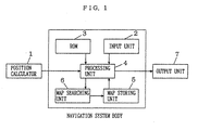
- FIG. 1 is a block diagram showing the structure of an automobile navigation apparatus according to a first embodiment of the present invention.
- the automobile navigation apparatus includes a position calculator 1, an input unit 2, ROM 3, a processing unit 4, a map storing unit 5, a map searching unit 6, and an output unit 7.
- the position calculator 1 calculates the current position of a vehicle on a map. This is realized by various methods such as detecting distance traveled by the vehicle through a vehicle speed sensor, detecting a direction of travel of the vehicle through a gyroscopic sensor, obtaining a correspondence between a locus of travel of the vehicle and a road shape on the map, or detecting an absolute position on the earth by receiving radio waves from a GPS satellite, or by combination of these sensors.
- the input unit 2 is a unit for inputting information based on an operation by an operator and other external information to a navigation system body.
- the ROM 3 stores a program for controlling the entire system.
- a rewritable recording medium such as a hard disk may be provided to store a program provided in a form of online or offline.
- the processing unit 4 controls the navigation system body according to the program stored in the ROM 3.
- the map searching unit 6 searches map data required for display or data processing.
- the map storing unit 5 is formed of a recording medium such as a CD-ROM which stores the map data, and its driving unit.
- the output unit 7 is to suggest the map data and processing results in the processing unit 4 to the operator.
- Each processing shown in the embodiment may be realized as software by using a computer, or may be realized by using dedicated hardware circuits having each function of the processings.
- the embodiment is characterized in that coordinates of four vertexes of the map data to be used for display are subjected to a three-dimensional coordinate transformation and a map is mapped as a texture on the transformed coordinates, whereby bird's eye view map display is performed so that the forward road can be widely viewed by processings with a small calculation load and various character symbol information is displayed on the map in a form where the operator can easily recognize the information.
- the map is divided by a predetermined range as a unit, and is structured by a plurality of layers (scales) to vary the level of detail of the map according to a display range. Therefore, it is required to prepare a map including the center of display and a plurality of its peripheral maps in an appropriate scale to display an arbitrary range of the map centering on an arbitrary point.
- a recorded range of each unit is constant in the map of the same layer.
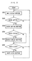
- FIG. 2 is a flowchart describing a processing procedure in the first embodiment of the present invention. The content of the processing of the first embodiment is subsequently described according to the flowchart.
- the processing unit 4 inputs a range of the map to be displayed on the basis of the operation of the operator through the input unit 2 or the current point of the vehicle obtained by the position calculator 1 (step S101).
- the display range of the map may be decided by the center of display and a display scale, or may be specified by, for example, upper-left and lower-right coordinates and then a suitable display scale for the range may be decided. In either way, in step S101, the center coordinates of display and the display scale are decided.
- the processing unit 4 searches the map including the center of display and the peripheral maps using the map searching unit 6 to read the corresponding maps from the map storing unit 5 (step S102).
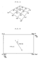
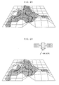
- the number of peripheral maps to be prepared has no limit, a map unit including the center of display and eight adjacent map units are read in the present embodiment, and the nine map units are arranged on the X-Y plane of the XYZ coordinate system shown in FIG. 4.
- the center part diagonally shaded is the map unit including the center of display.
- step S103 coordinates of an eye point where the map is viewed and a focus point are inputted.
- the focus point represents the center of display, which may be a position inputted by the operator through the input unit 2 or the current position of the vehicle obtained by the position calculator 1.
- the eye point is set above and behind the focus point. Therefore, since the focus point is on the map plane, its Z coordinate is 0.
- the eye point has a positive Z coordinate.
- the processing unit 4 calculates a transformation matrix of the eye point coordinates as a determinant of 3 ⁇ 3 shown in the following equation (1) (step S104).
- the processing unit 4 calculates eye point coordinates [x", y", z"] of the four vertexes of the each map unit using the equation (1), and also performs a perspective transformation using the following equation (2) (step S105).
- [x',y'] [(x"//z")dist,(y"/z")dist]
- the center of display is the origin of the coordinates. Furthermore, dist in the equation (2) is a parameter designating the depth from the eye point, which is set in the range of 300 to 1000 in the embodiment. In this way, an eye point perspective transformation is applied to the coordinates of four vertexes of each map unit as shown in C1 to C16 in FIG. 4 to obtain C1' to C16' as shown in FIG. 5.
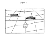
- the navigation apparatus not only a map background but also various character symbol information is required to be displayed.
- the character symbol information to be displayed are a balloon-shaped billboard representing a character string such as an intersection, a road, a name of a city, etc., and a mark representing a map symbol and a main building, etc.
- the character symbol information to be displayed is generically called a mark.
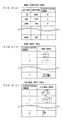
- the mark to be displayed on the map is generated using a mark coordinate table in FIG. 8(a) and a mark shape table in FIG. 8(b).
- the mark coordinate table provided for each map unit records coordinates (latitude and longitude) of the marks existed in the map range and classification numbers of the marks, and when the entire area of Japan is covered, its data size and the number of operation for creating the data are enormous.
- the mark shape table which stores shape data of the mark to be displayed by each classification is common to all of the units and the amount of the data can be smaller than in the case that the shape data is stored by each unit, the mark shape table is generally prepared separately from the mark coordinate table.
- the size and the number of operation for creating of the mark shape table are generally much smaller than those of the mark coordinate table.
- step S105 a coordinate transformation is applied to the coordinate of the mark in the map of the mark to be displayed on the basis of the equations (1) and (2). Since the display position of the mark generally has coordinates having one of the four vertexes of each map as the origin, the mark can be displayed on the map background by adding the coordinates of each mark to the origin.
- step S105 the coordinate transformation is applied to the four vertexes of each map units and the display position of each mark, and at the same time, the three-dimensional shape of each map is obtained from a 3-D mark shape table as shown in FIG. 8(c), for example, and then the coordinate transformation is applied to each points constructing the mark shape.
- the 3-D mark shape table is created by transforming the shape of the two-dimensional mark shape table into three-dimensional data with automatic or manual operation.
- the normal mark shape records a pattern of a dot string constructing the mark
- a 3-D mark shape records the number of dots constructing the mark and three-dimensional coordinates of each dot.
- images of the shapes themselves are shown for the sake of clarity.
- the processing unit 4 deforms each map unit according to the coordinates of the coordinate-transformed four vertexes (step S106). Any deforming method can be applied such as linear interpolation. Nine map units are deformed to be mapped on grids in FIG. 5, whereby the effect can be obtained such as the eye point perspective transformation is virtually applied to the whole display content of the maps.
- the processing unit 4 maps marks such as a character string and a symbol on the map background mapped at step S106 (step S107).
- the display position of the mark and the object on the map background are shifted in position.
- steps S105 and S106 since the eye point perspective transformation is applied to only the coordinates of four vertexes of the map background and its internal area is deformed by a method such as linear interpolation, the coordinates of a road in the map and the like are slightly shifted from those precisely subjected to the three-dimensional coordinate transformation as getting closer to the center of the map unit.
- the mark coordinates precisely subjected to the three-dimensional transformation at step S105 and the roads etc. of the map background deformed at step S106 are shifted in position, whereby, especially at the time of rotating the maps with movement of the eye point, the mark is disadvantageously shifted along an ellipse on the periphery of the original position.
- coordinate correction is performed according to the following equation (3) so that the display position of the mark is consistent with the object mapped on the map background.
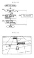
- FIG. 6 is a diagram showing a position of a mark P on the map unit and a viewing direction.
- Xmax and Ymax are maximum values of X coordinates and Y coordinates in the map unit, respectively, and C(Xh, Yh) is the center of the unit.
- vrx and vry are obtained by subtracting absolute values of x-Xh and y-Yh from Xh and Yh, respectively, and then multiplying by a constant v (which is decided by a parse, for example, 0.12), and are integers.
- the coordinate correction can be performed by adding dx and dy obtained by the equation (3) to x' and y' after the three-dimensional coordinate transformation, respectively.
- the mark on the three-dimensionally displayed map is distributed to the right and left sides of the focus point position to prevent the road adjacent to the center of display from being hidden, so that the forward direction of travel on the display map can be looked through.
- the absolute value of y' coordinate after perspective coordinate transformation designates the distance in the right or left directions from the center of the display screen, and y' coordinate designates whether a sign is on the right or the left sides. In the present embodiment, a positive sign indicates the right side of the screen, and a negative sign indicates the left side of the screen.
- the mark is mapped on the map background.
- the current position mark of the vehicle is mapped on the map ground.
- the processing unit 4 clips the display area with a broken line in FIG. 5 (step S108), to make the output unit 7 display the display area in the broken line in FIG. 5 (step S109).
- the map in an arbitrary position covering an arbitrary range can thus be three-dimensionally displayed.
- the processing unit 4 determines whether to change the eye point and focus point (step S110), and returns to step S103 to repeat the operation up to step S109 when the processing unit 4 determines to change.
- That the eye point or the focus point is to be changed is applied to a case where the current position of the vehicle is changed as the vehicle moves, or a case where the map is scrolled by the input operation by the operator through the input unit 2.
- the map is displayed centering on the focus point position.
- a current position indicating mark designating the direction of the current position of the vehicle is displayed at the center of the screen.
- An example of a current position mark and the current position indicating mark is shown in FIG. 27. The relation between the displayed map and the current position of the vehicle can thus easily grasped even if the current position of the vehicle is out of the map display range.
- processing unit 4 determines whether to change the display range (step S111), and returns to step S101 to repeat the operation up to step S109 when the processing unit 4 determines to change.
- three-dimensional map display can be achieved with a less calculation load by subjecting only four vertexes of the map unit to the three-dimensional coordinate transformation and deforming to map the map on the transformed coordinates. Furthermore, setting the eye point above and behind the focus point allows the map in the direction of travel to be widely displayed.
- the character symbol information By interpolating the coordinates of the character symbol information displayed on the three-dimensionally transformed map, the character symbol information can be displayed without incompatibility even at the map rotation.
- the name of the place and the size of the mark on the three-dimensionally displayed map are changed according to the distance from the current position to advantageously be able to emphasize a three-dimensional effect of the map, and to increase the range at a glance for a far-off mark as well as to display a nearby mark in detail.
- the billboard of the name of the place, the intersection, etc., and other marks are distributed to the right and left sides of the focus point position for displayed, whereby the character symbol information can be provided for the operator without preventing visibility of the direction of travel on the displayed map.
- a moving picture such as animation may be used.
- z which is a distance from the eye point after the eye point coordinate transformation is used at the time of calculating the enlargement rate
- anything may be used as long as the same effect is brought.
- using y' after the perspective transformation instead of z" can bring the same effect by changing constants.
- each point constructing each mark's shape is subjected to the coordinate transformation, only the display position of each mark may be subjected to the coordinate transformation and the three-dimensional shape data may be displayed without the transformation.
- a device capable of obtaining traffic information such as an FM multiplex receiver as the input unit 2 may be provided and the obtained traffic information may be superposingly displayed on the three-dimensionally transformed map.
- the traffic information is obtained from the input unit 2, and coordinates of congestion information and traffic control information are matched to the coordinates of the displayed map so as to be superposingly displayed on the map.
- the matching can be performed by transforming the reference of the coordinates defined in the format of the traffic information into coordinate values in the map unit.
- the congestion information is concomitant to the road, the road on which each congestion information depends is selected from the map for display.
- the corresponding road can be generally specified from latitude and longitude information.
- vector data of the specified road is subjected to the coordinate transformation together with the coordinates of four vertexes of the map unit.
- coordinate values of the starting and end points of each road vector are required to be corrected as well as the mark coordinates.
- the congested road vector is rather isolatedly displayed for clear display of the congested road. Therefore, the coordinate transformation is performed after z coordinate of each road vector is set to a predetermined value (for example, 20m).
- control information such as suspension of traffic is information depending on the points
- the 3-D control information mark can be displayed in the same processing as in the case of the mark.
- a display example is shown in FIG. 14.
- a represents a congested section and b is the control information mark representing suspension of traffic.
- the congestion information and traffic control can be plainly displayed.
- the input unit may be structured by combining a piezoelectric element so that an electric signal corresponding to the intensity of pushing a button is inputted to the input unit, and may be able to adjust a scroll speed according to the electric signal.
- thee scroll speed can be finely adjusted according to the intensity of pushing the button and fine scroll can be easily performed.
- an automotive navigation apparatus according to a second embodiment of the present invention is subsequently described.
- the basic structure of the automotive navigation apparatus of the second embodiment is the same as that of the first embodiment in FIG. 1. That is, in the second embodiment, a program stored in the ROM 3 of FIG. 1 is different from the program in the first embodiment. Therefore, the second embodiment is subsequently described referring to FIG. 1.
- the second embodiment is mainly characterized in that, on the three-dimensionally displayed map as described in the first embodiment, a route from a starting point to a destination can be easily set and the set route can be plainly provided for the operator.
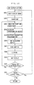
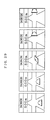
- FIGS. 9 to 13 are flowcharts describing processing procedures in the second embodiment of the present invention. The content of the processings of the second embodiment is subsequently described according to the flowcharts.
- the processing unit 4 calls a map display routine (step S201 in FIG. 9).
- the processing procedure of the map display routine is shown in a flowchart in FIG. 10.
- the processings from steps S301 through S309 in FIG. 10 correspond to the processings from steps S101 through S109 in FIG. 2 of the first embodiment, respectively.
- the processing unit 4 determines whether a route is to be set (step S202 in FIG. 9). When the route is not to be set, the unit returns to step S201 to display the map. When the route is to be set, the unit goes to step S203 to call a route setting routine.
- FIG. 11 shows a processing procedure of the route setting routine.
- the route setting routine as the map is displayed being scrolled or rotated, the route is set from the starting point to the destination.
- the input unit 2 specifies a focus point position, and its adjacent maps are displayed on the output unit 7(step S401).
- a road adjacent to the focus point of the map is selected (step S402).
- the adjacent road normal to the focus point can be selected as the closest road.
- the processing is performed every time the focus point is updated, i.e., the map is scrolled, to allow to select a consecutive road.
- the starting point of the route is taken as a point first selected at step S402.
- the processing unit 4 judges whether the focus point reaches the destination by input from an operational switch (included in the input unit 2) (step S403). When the focus point has not reached the destination, the unit makes a transition to step S401. On the other hand, when the focus point is at the destination, the unit makes a transition to step S204 in FIG. 9 to determine whether the route set at step S203 is displayed. When the route is displayed, the unit goes to step S205 to call a route display routine. When the route is not displayed, the unit goes to step S206 to determine whether to perform a route guide.
- FIG. 12 shows a processing procedure of the route display routine.
- the map is automatically scrolled or rotated to be provided for the operator.
- the processing unit 4 first reads coordinates of the starting point of the route (step S501). Then, the processing unit 4 makes the output unit 7 display the three-dimensional map taking the starting point read at step S501 as the focus point (step S502). The processing unit 4 returns to step S501 to take a point advanced by a prescribed distance on the route, and again displays the map at step S502.
- the processing unit 4 repeats the processings at steps S501 and S502 to provide the route from the starting point to the destination for the operator while automatically scrolling the map.
- step S206 it is determined whether a route guide is performed according to the set route at step S203.
- the unit returns to step S201 to display the map.
- route guide is performed, on the other hand, the unit goes to step S207 to call a route guide routine.
- FIG. 13 shows a processing procedure of the route guide routine.
- a route guide is performed for the operator according to the route set at step S203.
- step S701 it is determined whether the route has been calculated.
- a message such as "No route set" is outputted at step S702.
- step S703 a moving picture guide screen forming processing is performed.
- the screen is formed by generating a moving picture by graphics such as an arrow on the enlarged intersection view displayed with a name of the intersection to be turned at and the distance to the intersection.
- FIG. 29 shows an example of the generated moving picture guide screen.
- step S704 the screen data generated at step S703 is displayed as a moving picture.
- the operator operates the operation switch, feeling like as if he or she drove, to easily set the route from the starting point to the destination. Furthermore, according to the set route, the user can associate the real movement of the vehicle by displaying right-and-left turn information at the intersection using a moving picture, and easily grasp the direction of travel at the intersection.
- the focus point at the start of the processing is the starting point of the route
- a processing of setting an arbitrary focus point as the starting point may be added.
- intersection information on an arbitrary route selected by the user may be generated by a moving picture.
- a state of a guide vehicle moving toward the guide direction may be displayed as a moving picture, instead of the arrow.
- Information on the intersections on the whole forward route may be sequentially generated for display to provide the user with intersection images on the whole route.
- the eye point coordinates may be varied according to automatic or user's operation.
- the map may operate to display a map adjacent to the destination and set a destination mark on the displayed map, whereby the optimum route from the starting point to the destination may be automatically obtained by the Dijkstra method etc.
- the destination point may be automatically retrieved from a map database by a telephone number or a keyword.
- the map from the starting point to the destination is automatically scrolled as the set route is traced, an overview of the route may be provided for the operator by linear scrolling from the starting point to the destination.
- an automotive navigation apparatus according to a third embodiment of the present invention is subsequently described.
- the basic structure of the automotive navigation apparatus of the third embodiment is the same as that of the first embodiment in FIG. 1. That is, in the third embodiment, a program stored in the ROM 3 of FIG. 1 is different from the program in the first embodiment. Therefore, the third embodiment is subsequently described referring to FIG. 1.
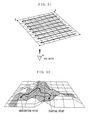
- the third embodiment is mainly characterized in that the map unit is divided into fine blocks, altitude values are assigned to four vertexes of each fine block for the three-dimensional coordinate transformation, and the fine blocks are deformed to be mapped on the transformed coordinates, whereby a terrain are three-dimensionally displayed with a simple processing using only a plane map and altitude values.
- FIG. 15 is a flowchart describing a processing procedure in the third embodiment of the present invention. The content of the processing of the third embodiment is subsequently described referring to the flowchart.
- the processing unit 4 inputs a range and scale of the map to be displayed on the basis of an operation by the operator through the input unit 2 or the current position of the vehicle obtained in the position calculator 1(step S601).
- the processing unit 4 searches a map corresponding to the scale and range decided at step S601 by using the map searching unit 6 to read the corresponding map data from the map storing unit 5 (step S602).
- the map data is divided into units by a prescribed range and is further formed of a plurality of layers (scales) which differ in a degree of details. Therefore, in order to display the map of an arbitrary range centering on an arbitrary point, the map unit including the center of display and eight adjacent map units thereof should be read in the corresponding scale.
- the read map unit is divided in eight in the latitude and longitude directions as shown in FIG. 16(b), that is, divided in the total of 64 fine blocks. Next, altitude values are assigned to each vertex of the fine blocks obtained by division.
- FIG. 17 (a) shows the upper left, the longitude direction, the latitude direction and the altitude value direction.
- the x axis, the y axis and the z axis respectively, and the vertexes of each fine block of each map unit are represented as P(x, y, z).
- FIG. 17 (b) shows the center map unit extracted from nine map units.
- the processing unit 4 inputs the eye point Pv (xv, yv, zv) and the focus point Pf(xf, yf, zf) (step S603).
- the processing unit 4 calculates a transformation matrix from a world coordinate system to an eye point coordinate system as a determinant of 3 ⁇ 3 of the equation (1) (step S604).
- the processing unit 4 transforms vertexes of each fine block of each map unit into eye point coordinates [x", y", z”] according to the equation (1) and performs the perspective transformation according to the equation (2) (step S605).
- the center of display is the origin of the coordinates.
- dist of the equation (2) designates a depth from the eye point and is set to the range of 300 to 1000 in the embodiment.
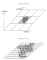
- FIG. 18 is a result of the above described coordinate transformation with respect to each fine block of the map unit in FIG. 17 (b).
- the processing unit 4 divides a map background into 8 ⁇ 8 fine blocks shown in FIG. 19 (step S606).
- the fine blocks obtained by division are used for texture mapping at step S608 which is subsequently described.
- the processing unit 4 judges the order for displaying the fine blocks obtained by division at step S606 (step S607).
- This is to perform a face hiding processing for hiding a face which cannot be seen from the set eye point position.
- the face hiding processing is generally realized by sorting all faces to be drawn in distant order from the eye point, the most distant first, and writing over the faces in the order from the most distant to the closest for display.
- a simplified face hiding processing is used to decrease a load on a drawing processing.
- the simplified face hiding processing is subsequently descried in detail.
- the nine map units read at step S602 four vertexes which decides a read range are subjected to the eye point transformation .
- the four vertexes which decides the read range are four points of C1, C4, C13 and C16 when the nine read map units are arranged as in FIG. 4. In this situation, z coordinates of the four vertexes are set to 0.
- the four vertexes subjected to the perspective transformation are sorted in the order from the eye point, the most distant first. After sorting, the most distant point from the eye point is A, and the second most distant point is B. Furthermore, as shown in FIG. 21, a scanning direction is decided from the point A to the point B. In drawing, the face hiding processing is performed by sequentially superposing each fine block in the scanning direction, as subsequently described.
- the processing unit 4 maps the fine blocks of the map background divided at step S606 in the order decided at step S607 (step S608).
- the fine blocks of the map background divided at step S606 is first deformed according to the coordinates subjected to the perspective transformation at step S605. Any method including linear interpolation can be used for deformation.
- Each of the deformed fine block is then sequentially superposed in the drawing order decided at step S607.
- FIG. 20 shows the result of mapping the map background divided into the fine blocks on the coordinates subjected to the perspective transformation on the basis of the altitude value data.
- the processing unit 4 clips the texture-mapped image as described above (step S609) and makes the output unit 7 display an area in a drawing window (step S610).
- the processing unit 4 determines whether the eye point or the focus point is changed (step S611), and returns to step S603 to repeat the processings up to step S610 when the point is changed.
- the processing unit 4 determines whether the display range is changed (step S612), and when the display range is changed, the unit returns to step S601 to repeat the processings up to step S610.
- map display three-dimensionally representing terrain roughness can be performed with an easy processing using only the plane map and the altitude value data.
- a road is generally represented with a solid line on map data, and a tunnel section in each road is generally represented with a broken line as shown in FIG. 24.
- map data is mapped as it is as a texture
- a mountainous part which a tunnel is through is unnaturally represented such as that a broken line is displayed along ridges of mountains. Therefore, when such map background is mapped as a texture as at step S608, a section corresponding to the tunnel is extracted from a road network of each map unit for deletion, and then each unit is mapped.
- the map data is image data such as a bit map or an aerial photograph
- the part with the broken line can be extracted by using an image processing method such as template matching.
- the tunnel section can be directly extracted.
- the extracted tunnel section is deleted by a method such as pasting a background color.
- FIG. 25 shows the result of mapping the map background shown in FIG. 24 as a texture after the tunnel section is deleted.
- Route setting from the starting point to the destination can be attained with the map being rotated or scrolled in a sense as if you drove on the map where the terrain is three-dimensionally displayed, by a method as shown in the second embodiment. Furthermore, when the route is set as described above, three-dimensional coordinates in the eye point coordinate system of dot strings forming each road are stored, and when all the route is finally determined, the route can be displayed on the map three-dimensionally displaying the terrain as shown in FIG. 22 by changing to display the color of the road and a line width as to the stored dot strings.
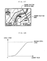
- Radio waves transmitted from the GPS satellite include two signals: an orbit signal representing the position of the satellite on the orbit and a signal representing time of day of signal transmission. Therefore, the position of the GPS satellite is detected from the orbit signal, and is inputted as eye point coordinates. At the same time, the calculated current position of the vehicle is inputted as focus point coordinates. At this situation, when the radio waves from the GPS cannot be received, a vehicle position detected by other sensors is inputted as the focus point coordinates. Based on the inputted eye point coordinates and the focus point coordinates, terrain display as described above is performed, and the current position of the vehicle is simultaneously displayed on the map. As a result, as shown in FIG.
- a state can be determined as such that the radio waves from the GPS satellite can be easily received.
- the vehicle position is displayed on the tunnel section or cannot be displayed behind a recess of a mountain, that is, when the GPS satellite cannot look over the vehicle, it can be determined that a receiving state of the radio waves from the GPS satellite is not good.
- the terrain is three-dimensionally displayed with the position of the GPS satellite as an eye point and simultaneously the vehicle position is displayed on the map, whereby the receiving state of the radio waves from the GPS satellite can be visually provided for a driver.
- the scale of the map When the scale of the map is small, a range which the map covers is large. Thus, in three-dimensional display, the change of terrain roughness of mountains and valleys is represented to allow map display with reality. On the other hand, when the scale of the map is large, a range which the map covers is small. Thus, an effect of three-dimensional display of the terrain roughness is small and the map visibility becomes even worse in the mountainous part, Therefore, the scale of the altitude value data used for coordinate transformation may be variable between layers of the displayed map and the terrain roughness may be adjusted accordingly.
- the number of division may be set according to resolution of the available altitude value data.
- map data is mapped as a texture
- image data such as an aerial photograph may be used.
Claims (18)
- Système de navigation pour automobile, comportant :le système étant caractérisé par :des moyens de mémorisation de cartes (5) mémorisant des données cartographiques,des moyens d'acquisition de cartes faisant l'acquisition des données cartographiques mémorisées dans lesdits moyens de mémorisation de cartes (S102),des moyens d'entrée de points de vue entrant des coordonnées de points de vue et des coordonnées de points focaux pour visualiser les données cartographiques acquises par lesdits moyens d'acquisition de cartes (S103),des moyens de transformation de coordonnées exécutant une transformation de coordonnées tridimensionnelles d'un petit groupe de points arbitrairement choisis appartenant aux données cartographiques acquises par lesdits moyens d'acquisition de cartes sur la base des coordonnées de points de vue et des coordonnées de points focaux entrées par lesdits moyens d'entrée de points de vue (S105),des moyens déformant les données cartographiques acquises par lesdits moyens d'acquisition de cartes de telle sorte qu'elles coïncident avec les coordonnées transformées par lesdits moyens de transformation de coordonnées et représentant les données déformées (S106),des moyens de découpage découpant les données cartographiques représentées par lesdits moyens de cartographie (S108), etdes moyens de sortie délivrant en sortie une zone de carte découpée par lesdits moyens de découpage.
- Dispositif de navigation pour automobile selon la revendication 1, dans lequel
lesdits moyens de transformation de coordonnées exécutent la transformation de coordonnées tridimensionnelles des points choisis, appartenant aux données cartographiques acquises par lesdits moyens d'acquisition de cartes sur la base des coordonnées de points de vue et des coordonnées de points focaux entrées par lesdits moyens d'entrée de points de vue et la transformation de coordonnées tridimensionnelles des coordonnées de points de référence d'une marque prescrite (P) incluse dans lesdites données cartographiques, et corrigent en outre un décalage entre un arrière-plan de carte et lesdites coordonnées de points de référence après la transformation, et
lesdits moyens de sortie affichent d'une manière superposée la marque prescrite soumise à une correction de coordonnées sur une carte. - Dispositif de navigation pour automobile selon la revendication 2, dans lequel lesdits moyens de sortie changent pour délivrer en sortie une taille de la marque prescrite sur la base d'une relation positionnelle relative entre une position de point focal entrée par lesdits moyens d'entrée de points de vue et les coordonnées de point de référence de ladite marque prescrite.
- Dispositif de navigation pour automobile selon la revendication 2, dans lequel lesdits moyens de sortie changent pour délivrer en sortie un motif de forme de la marque prescrite sur la base d'une relation positionnelle relative entre un point focal entré par lesdits moyens d'entrée de points de vue et les coordonnées de point de référence de ladite marque prescrite.
- Dispositif de navigation pour automobile selon la revendication 1, dans lequel lesdits moyens de transformation de coordonnées exécutent la transformation de coordonnées tridimensionnelles des données cartographiques acquises par lesdits moyens d'acquisition de cartes sur la base des coordonnées de points de vue et des coordonnées de points focaux entrées par lesdits moyens d'entrée de points de vue et la transformation de coordonnées tridimensionnelles d'une marque de forme tridimensionnelle incluse dans lesdites données cartographiques.
- Dispositif de navigation pour automobile selon la revendication 1, comportant en outre des moyens de définition de trajet (S203) obtenant un trajet entre des positions arbitraires.
- Dispositif de navigation pour automobile selon la revendication 1, comportant en outre des moyens d'affichage d'informations de trafic (figure 14) recevant des informations de trafic et affichant en trois dimensions et d'une manière superposée des informations de trafic.
- Dispositif de navigation pour automobile selon la revendication 1, comportant en outre des moyens de calcul de position (1) détectant une position courante d'un véhicule, une position du véhicule détectée par lesdits moyens de calcul de position étant affichée d'une manière superposée sur la carte.
- Dispositif de navigation pour automobile selon la revendication 1, comportant en outre :des moyens de mémorisation de valeurs d'altitude mémorisant des données de valeurs d'altitude,des moyens d'acquisition de valeurs d'altitude faisant l'acquisition des données de valeurs d'altitude correspondant aux données cartographiques acquises par lesdits moyens d'acquisition de cartes à partir desdits moyens de mémorisation de valeurs d'altitude, etdes moyens de division de carte (S606) divisant les données cartographiques acquises par lesdits moyens d'acquisition de cartes en blocs fins (figure 16b),lesdits moyens de transformation de coordonnées exécutant la transformation de coordonnées tridimensionnelles en utilisant les données de valeurs d'altitude acquises par lesdits moyens d'acquisition de valeurs d'altitude, etlesdits moyens de cartographie effectuant une déformation pour représenter les blocs fins obtenus par la division effectuée par lesdits moyens de division de carte sur les coordonnées transformées par lesdits moyens de transformation de coordonnées, et comportant en outredes moyens de traitement de masquage de face exécutant un traitement de masquage de face sur les blocs fins représentés par lesdits moyens de cartographie.
- Dispositif de navigation pour automobile selon la revendication 9, comportant en outre des moyens de calcul de position (1) détectant une position courante d'un véhicule, une position du véhicule détectée par lesdits moyens de calcul de position étant affichée d'une manière superposée sur la carte.
- Dispositif de navigation pour automobile selon la revendication 9, dans lequel lesdits moyens de traitement de masquage de face écrivent sur chacun des blocs fins obtenus par la division effectuée par lesdits moyens de division de carte pendant un balayage dans une direction prescrite (figure 21).
- Dispositif de navigation pour automobile selon la revendication 11, dans lequel lesdits moyens de traitement de masquage de face effectuent un balayage pour délivrer en sortie lesdites données cartographiques soumises à la transformation de coordonnées à partir d'un point le plus distant (A) jusqu'à un second point le plus distant (B) par rapport à un point de vue entré par lesdits moyens d'entrée de points de vue parmi quatre sommets des données cartographiques acquises par lesdits moyens d'acquisition de cartes qui sont soumises à une transformation de point de vue dans lesdits moyens de transformation de coordonnées.
- Dispositif de navigation pour automobile selon la revendication 9, comportant en outre :des moyens de définition de trajet obtenant un trajet entre des points arbitraires, etdes moyens d'affichage de vue transversale délivrant en sortie des valeurs d'altitude sur le trajet défini par lesdits moyens de définition de trajet sous la forme d'une vue transversale.
- Dispositif de navigation pour automobile selon la revendication 9, dans lequel lesdits moyens de cartographie reconnaissent une section de tunnel sur les données cartographiques acquises par lesdits moyens d'acquisition de cartes, et suppriment en outre la section de représentation du tunnel (figures 24 et 25).
- Dispositif de navigation pour automobile selon la revendication 10, dans lequel lesdits moyens de calcul de position comportent une fonction de suppression de la position du véhicule en recevant des ondes radio provenant d'un satellite GPS, et lesdits moyens d'entrée de points de vue obtiennent des coordonnées du satellite GPS reçues par lesdits moyens de calcul de position en tant que position de point de vue.
- Dispositif de navigation pour automobile selon la revendication 9, dans lequel lesdits moyens de transformation de coordonnées exécutent la transformation de coordonnées tout en changeant une échelle des valeurs d'altitude acquises par lesdits moyens d'acquisition de valeurs d'altitude sur la base d'une couche des données cartographiques acquises par lesdits moyens d'acquisition de cartes ou d'une position de point de vue entrée par lesdits moyens d'entrée de points de vue.
- Support d'enregistrement, dans lequel
des moyens de mémorisation de données cartographiques (5) mémorisent préalablement des données cartographiques,
le support d'enregistrement est caractérisé en ce qu'il mémorise un programme de logiciel pour exécuter un procédé comportant :une première étape consistant à acquérir les données cartographiques à partir desdits moyens de mémorisation de données cartographiques (S102),une deuxième étape consistant à entrer des coordonnées de points de vue et des coordonnées de points focaux à partir desquelles sont visualisées les données cartographiques acquises à ladite première étape (S103),une troisième étape pour exécuter une transformation de coordonnées tridimensionnelles d'un petit groupe de points arbitrairement choisis appartenant aux données cartographiques acquises à ladite première étape sur la base des coordonnées de points de vues et des coordonnées de points focaux entrées à ladite deuxième étape (S105),une quatrième étape pour déformer les données cartographiques acquises à ladite première étape de telle sorte qu'elles coïncident avec les coordonnées transformées à ladite troisième étape et pour représenter les données déformées (S106),une cinquième étape pour découper les données cartographiques représentées à ladite quatrième étape (S108), etune sixième étape pour délivrer en sortie une zone cartographique découpée à ladite cinquième étape (S109). - Support d'enregistrement selon la revendication 17, dans lequel
les moyens de mémorisation de valeurs d'altitude mémorisent préalablement des données de valeurs d'altitude,
le support d'enregistrement mémorisant le programme de logiciel pour exécuter le procédé comporte en outre :une septième étape pour acquérir les données de valeurs d'altitude correspondant aux données cartographiques acquises à ladite première étape à partir desdits moyens de mémorisation de valeurs d'altitude, etune huitième étape pour diviser les données cartographiques acquises par lesdits moyens d'acquisition de données cartographiques en blocs fins (S606),ladite troisième étape exécutant la transformation de coordonnées tridimensionnelles en utilisant les données de valeurs d'altitude acquises à ladite septième étape, etune quatrième étape effectuant une déformation pour représenter les blocs fins obtenus par la division à ladite huitième étape sur les coordonnées transformées à ladite troisième étape, et comportant en outreune neuvième étape pour exécuter un traitement de masquage de face sur les blocs fins représentés à ladite quatrième étape.
Priority Applications (1)
| Application Number | Priority Date | Filing Date | Title |
|---|---|---|---|
| EP01118872A EP1174843B1 (fr) | 1995-06-13 | 1996-06-11 | Appareil de navigation pour automobile et support d'enregistrement mémorisant le programme à cet effet |
Applications Claiming Priority (6)
| Application Number | Priority Date | Filing Date | Title |
|---|---|---|---|
| JP146535/95 | 1995-06-13 | ||
| JP14653595A JP3262690B2 (ja) | 1995-06-13 | 1995-06-13 | 車載用ナビゲーション装置 |
| JP14653595 | 1995-06-13 | ||
| JP232910/95 | 1995-09-11 | ||
| JP23291095 | 1995-09-11 | ||
| JP23291095 | 1995-09-11 |
Related Child Applications (1)
| Application Number | Title | Priority Date | Filing Date |
|---|---|---|---|
| EP01118872A Division EP1174843B1 (fr) | 1995-06-13 | 1996-06-11 | Appareil de navigation pour automobile et support d'enregistrement mémorisant le programme à cet effet |
Publications (2)
| Publication Number | Publication Date |
|---|---|
| EP0749103A1 EP0749103A1 (fr) | 1996-12-18 |
| EP0749103B1 true EP0749103B1 (fr) | 2003-05-14 |
Family
ID=26477348
Family Applications (2)
| Application Number | Title | Priority Date | Filing Date |
|---|---|---|---|
| EP96109327A Expired - Lifetime EP0749103B1 (fr) | 1995-06-13 | 1996-06-11 | Appareil de navigation pour automobile et support d'enregistrement mémorisant le programme à cet effet |
| EP01118872A Expired - Lifetime EP1174843B1 (fr) | 1995-06-13 | 1996-06-11 | Appareil de navigation pour automobile et support d'enregistrement mémorisant le programme à cet effet |
Family Applications After (1)
| Application Number | Title | Priority Date | Filing Date |
|---|---|---|---|
| EP01118872A Expired - Lifetime EP1174843B1 (fr) | 1995-06-13 | 1996-06-11 | Appareil de navigation pour automobile et support d'enregistrement mémorisant le programme à cet effet |
Country Status (4)
| Country | Link |
|---|---|
| US (1) | US5913918A (fr) |
| EP (2) | EP0749103B1 (fr) |
| KR (1) | KR0180813B1 (fr) |
| DE (2) | DE69628091T2 (fr) |
Cited By (8)
| Publication number | Priority date | Publication date | Assignee | Title |
|---|---|---|---|---|
| US8531312B2 (en) | 2002-03-05 | 2013-09-10 | Triangle Software Llc | Method for choosing a traffic route |
| US8619072B2 (en) | 2009-03-04 | 2013-12-31 | Triangle Software Llc | Controlling a three-dimensional virtual broadcast presentation |
| US8660780B2 (en) | 2003-07-25 | 2014-02-25 | Pelmorex Canada Inc. | System and method for delivering departure notifications |
| US8718910B2 (en) | 2010-11-14 | 2014-05-06 | Pelmorex Canada Inc. | Crowd sourced traffic reporting |
| US8725396B2 (en) | 2011-05-18 | 2014-05-13 | Pelmorex Canada Inc. | System for providing traffic data and driving efficiency data |
| US8781718B2 (en) | 2012-01-27 | 2014-07-15 | Pelmorex Canada Inc. | Estimating time travel distributions on signalized arterials |
| US8982116B2 (en) | 2009-03-04 | 2015-03-17 | Pelmorex Canada Inc. | Touch screen based interaction with traffic data |
| US9046924B2 (en) | 2009-03-04 | 2015-06-02 | Pelmorex Canada Inc. | Gesture based interaction with traffic data |
Families Citing this family (74)
| Publication number | Priority date | Publication date | Assignee | Title |
|---|---|---|---|---|
| US6654014B2 (en) * | 1995-04-20 | 2003-11-25 | Yoshinori Endo | Bird's-eye view forming method, map display apparatus and navigation system |
| JP3375258B2 (ja) * | 1996-11-07 | 2003-02-10 | 株式会社日立製作所 | 地図表示方法及び装置並びにその装置を備えたナビゲーション装置 |
| JP3419648B2 (ja) * | 1997-05-27 | 2003-06-23 | 株式会社日立製作所 | ナビゲーション装置 |
| DE69835122T2 (de) * | 1997-05-27 | 2006-12-21 | Xanavi Informatics Corp., Zama | Navigationsvorrichtung |
| JPH1152845A (ja) * | 1997-08-08 | 1999-02-26 | Aisin Aw Co Ltd | 地図表示装置及び記録媒体 |
| FR2774166B1 (fr) * | 1998-01-27 | 2000-03-31 | Philips Electronics Nv | Appareil de guidage d'un vehicule permettant un balayage d'itineraire |
| JP3511570B2 (ja) * | 1998-03-06 | 2004-03-29 | パイオニア株式会社 | 地図情報表示装置及びナビゲーション用プログラムを記録した記録媒体 |
| KR20000009806A (ko) | 1998-07-28 | 2000-02-15 | 이흥수 | 벡터데이터로 표현된 화상정보를 전송하는 시스템 및 그 방법 |
| DE19852994A1 (de) * | 1998-11-17 | 2000-05-18 | Volkswagen Ag | Navigationseinrichtung für Kraftfahrzeuge |
| US6456299B1 (en) * | 1999-03-15 | 2002-09-24 | Joseph R. Trombley | Map making process |
| JP2000305452A (ja) | 1999-04-21 | 2000-11-02 | Sony Corp | 電子地図装置および電子地図の表示方法 |
| JP3475123B2 (ja) * | 1999-05-24 | 2003-12-08 | アイシン・エィ・ダブリュ株式会社 | ナビゲーション装置および記憶媒体 |
| JP3596805B2 (ja) * | 1999-07-29 | 2004-12-02 | 松下電器産業株式会社 | 情報端末装置および経路案内方法 |
| US6317689B1 (en) | 2000-02-09 | 2001-11-13 | Garmin Corporation | Method and device for displaying animated navigation information |
| DE60137660D1 (de) | 2000-03-17 | 2009-04-02 | Panasonic Corp | Kartenanzeige- und Navigationsvorrichtung |
| US6650253B2 (en) * | 2000-05-30 | 2003-11-18 | Matsushita Electric Industrial Co., Ltd. | Map display device, map display method, and computer program for use in map display device |
| DE10039235C2 (de) * | 2000-08-11 | 2003-01-30 | Bosch Gmbh Robert | Verfahren zur Darstellung einer Fahrstrecke |
| EP1195577A3 (fr) * | 2000-10-06 | 2008-12-03 | Panasonic Corporation | Dispositif d'affichage de plans, méthode d'affichage de plans, et logiciel à utiliser dans un dispositif d'affichage de plans |
| JP2004533678A (ja) * | 2001-03-27 | 2004-11-04 | コンピュータ アソシエイツ シンク,インコーポレイテッド | 立方根スケーリングを使用することによりポリゴンデータに対する空間的階層を決定するシステム及び方法 |
| JP3992227B2 (ja) * | 2002-04-26 | 2007-10-17 | パイオニア株式会社 | 3次元情報表示装置 |
| US20030202683A1 (en) * | 2002-04-30 | 2003-10-30 | Yue Ma | Vehicle navigation system that automatically translates roadside signs and objects |
| US20070103292A1 (en) * | 2002-07-02 | 2007-05-10 | Burkley Raymond T | Incident control system with multi-dimensional display |
| US6721660B2 (en) * | 2002-08-19 | 2004-04-13 | Korea Advanced Institute Of Science And Technology | Road extraction from images using template matching |
| JP4032355B2 (ja) * | 2003-03-27 | 2008-01-16 | カシオ計算機株式会社 | 表示処理装置、表示制御方法および表示処理プログラム |
| US7130740B2 (en) * | 2003-11-07 | 2006-10-31 | Motorola, Inc. | Method and apparatus for generation of real-time graphical descriptions in navigational systems |
| EP1531322A3 (fr) * | 2003-11-13 | 2007-09-05 | Matsushita Electric Industrial Co., Ltd. | Appareil d'affichage de carte |
| JP4211594B2 (ja) * | 2003-12-18 | 2009-01-21 | 日産自動車株式会社 | 3次元路面走行環境モデルおよび同モデルを備えた車両挙動制御システムの評価装置 |
| US20050177176A1 (en) | 2004-02-05 | 2005-08-11 | Craig Gerbi | Single-fold system for tissue approximation and fixation |
| JP2005283274A (ja) * | 2004-03-29 | 2005-10-13 | Fujinon Corp | 位置検出装置 |
| JP2005321370A (ja) * | 2004-04-05 | 2005-11-17 | Sony Corp | ナビゲーション装置、およびデータ処理方法、並びにコンピュータ・プログラム |
| US7376510B1 (en) * | 2004-11-05 | 2008-05-20 | Navteq North America, Llc | Map display for a navigation system |
| DE102004056985A1 (de) * | 2004-11-25 | 2006-06-08 | Siemens Ag | System und Verfahren zur Routenführung in unebenem Gelände |
| KR100677569B1 (ko) * | 2004-12-13 | 2007-02-02 | 삼성전자주식회사 | 입체영상장치 |
| US7908080B2 (en) | 2004-12-31 | 2011-03-15 | Google Inc. | Transportation routing |
| MX2007010948A (es) * | 2005-03-09 | 2008-03-10 | Tomtom Int Bv | Aparato y metodo para compilar una imagen combinada y mostrarla en una pantalla. |
| US8626440B2 (en) * | 2005-04-18 | 2014-01-07 | Navteq B.V. | Data-driven 3D traffic views with the view based on user-selected start and end geographical locations |
| US20060253246A1 (en) * | 2005-04-18 | 2006-11-09 | Cera Christopher D | Data-driven combined traffic/weather views |
| US8781736B2 (en) * | 2005-04-18 | 2014-07-15 | Navteq B.V. | Data-driven traffic views with continuous real-time rendering of traffic flow map |
| US20060247850A1 (en) * | 2005-04-18 | 2006-11-02 | Cera Christopher D | Data-driven traffic views with keyroute status |
| US7765055B2 (en) * | 2005-04-18 | 2010-07-27 | Traffic.Com, Inc. | Data-driven traffic views with the view based on a user-selected object of interest |
| US8207843B2 (en) | 2005-07-14 | 2012-06-26 | Huston Charles D | GPS-based location and messaging system and method |
| US9344842B2 (en) | 2005-07-14 | 2016-05-17 | Charles D. Huston | System and method for viewing golf using virtual reality |
| US8933967B2 (en) | 2005-07-14 | 2015-01-13 | Charles D. Huston | System and method for creating and sharing an event using a social network |
| US9445225B2 (en) * | 2005-07-14 | 2016-09-13 | Huston Family Trust | GPS based spectator and participant sport system and method |
| US7715980B2 (en) * | 2005-11-17 | 2010-05-11 | Microsoft Corporation | Schematic destination maps |
| KR100809524B1 (ko) * | 2005-12-08 | 2008-03-04 | 한국전자통신연구원 | 유비쿼터스 네트워크 기반의 네비게이션 장치와 서버를 이용한 교통정보 제공 시스템 및 방법 |
| DE102005063013B4 (de) | 2005-12-30 | 2021-12-02 | Robert Bosch Gmbh | Verfahren zur Darstellung einer Oberfläche und eine Vorrichtung hierfür |
| JP2007292713A (ja) * | 2006-03-30 | 2007-11-08 | Denso Corp | ナビゲーション装置 |
| DE102006052663A1 (de) | 2006-11-07 | 2008-05-08 | Navigon Ag | Vorrichtung und Verfahren zur Erstellung eines Textobjekts |
| JP4858197B2 (ja) | 2007-01-31 | 2012-01-18 | ソニー株式会社 | 情報処理装置、画像表示装置、情報処理システム、情報処理方法およびプログラム |
| US20100198509A1 (en) * | 2007-06-07 | 2010-08-05 | Qualcomm Incorporated | 3d maps rendering device and method |
| US20100225644A1 (en) * | 2009-03-05 | 2010-09-09 | Navteq North America, Llc | Method and System for Transitioning Between Views in a Traffic Report |
| JP5471751B2 (ja) * | 2010-04-09 | 2014-04-16 | 株式会社デンソー | ナビゲーション装置 |
| US8489331B2 (en) | 2010-04-29 | 2013-07-16 | Microsoft Corporation | Destination maps user interface |
| JP5732854B2 (ja) * | 2011-01-05 | 2015-06-10 | ソニー株式会社 | 表示制御装置、表示制御方法及びプログラム |
| JP5724396B2 (ja) * | 2011-01-13 | 2015-05-27 | ソニー株式会社 | 地図表示制御装置、地図表示制御方法、およびプログラム |
| GB2492381A (en) * | 2011-06-30 | 2013-01-02 | Tomtom Int Bv | Controlling a map displayed on a navigation apparatus in order to maximise the display of a remaining route |
| US20130197800A1 (en) * | 2012-01-31 | 2013-08-01 | Autotalks Ltd. | Method and system for gps augmentation using cooperative altitude learning |
| US9418672B2 (en) | 2012-06-05 | 2016-08-16 | Apple Inc. | Navigation application with adaptive instruction text |
| US9159153B2 (en) | 2012-06-05 | 2015-10-13 | Apple Inc. | Method, system and apparatus for providing visual feedback of a map view change |
| US9482296B2 (en) | 2012-06-05 | 2016-11-01 | Apple Inc. | Rendering road signs during navigation |
| US10156455B2 (en) | 2012-06-05 | 2018-12-18 | Apple Inc. | Context-aware voice guidance |
| US9886794B2 (en) | 2012-06-05 | 2018-02-06 | Apple Inc. | Problem reporting in maps |
| US8965696B2 (en) | 2012-06-05 | 2015-02-24 | Apple Inc. | Providing navigation instructions while operating navigation application in background |
| US10223909B2 (en) | 2012-10-18 | 2019-03-05 | Uber Technologies, Inc. | Estimating time travel distributions on signalized arterials |
| RU2528501C1 (ru) * | 2013-06-04 | 2014-09-20 | Федеральное Государственное унитарное предприятие "Российский Федеральный ядерный центр-Всероссийский научно-исследовательский институт экспериментальной физики-ФГУП "РФЯЦ-ВНИИЭФ" | Способ прогнозирования перемещений объектов движения в мегаполисе путем многофакторного моделирования перемещаемого транспортного потока |
| KR20150073269A (ko) * | 2013-12-20 | 2015-07-01 | 현대자동차주식회사 | 차량용 클러스터 장치 |
| JP6384254B2 (ja) * | 2014-10-10 | 2018-09-05 | 株式会社デンソー | 端末装置 |
| KR102395022B1 (ko) * | 2015-06-30 | 2022-05-06 | 현대오토에버 주식회사 | 지도 축적 변화에 따른 웹 벡터 지도 표시 시스템 및 방법 |
| EP4035943B1 (fr) * | 2016-11-01 | 2023-08-30 | Panasonic Intellectual Property Corporation of America | Procédé et dispositif d'affichage |
| JP2018205375A (ja) * | 2017-05-31 | 2018-12-27 | 富士ゼロックス株式会社 | 情報処理装置及びプログラム |
| US11120619B2 (en) * | 2018-11-12 | 2021-09-14 | Nintendo Co., Ltd. | Information processing apparatus, non-transitory computer-readable storage medium storing information processing program, information processing system, and information processing method |
| KR101977290B1 (ko) * | 2019-01-04 | 2019-05-10 | 국방과학연구소 | 2차원공간상에서 복수의 무인항공기의 출발점과 도착점을 할당하는 방법 및 그 방법을 구현하기 위한 시스템 |
| US20200393265A1 (en) * | 2019-06-11 | 2020-12-17 | DeepMap Inc. | Lane line determination for high definition maps |
Family Cites Families (13)
| Publication number | Priority date | Publication date | Assignee | Title |
|---|---|---|---|---|
| US4888712A (en) * | 1987-11-04 | 1989-12-19 | Schlumberger Systems, Inc. | Guardband clipping method and apparatus for 3-D graphics display system |
| NL8900056A (nl) * | 1989-01-11 | 1990-08-01 | Philips Nv | Werkwijze voor het visueel weergeven van een deel van een topografische kaart, alsmede inrichting geschikt voor een dergelijke werkwijze. |
| JPH0690041B2 (ja) * | 1989-06-26 | 1994-11-14 | 本田技研工業株式会社 | 移動体の現在位置表示装置 |
| NL8901695A (nl) * | 1989-07-04 | 1991-02-01 | Koninkl Philips Electronics Nv | Werkwijze voor het weergeven van navigatiegegevens voor een voertuig in een omgevingsbeeld van het voertuig, navigatiesysteem voor het uitvoeren van de werkwijze, alsmede voertuig voorzien van een navigatiesysteem. |
| US5276785A (en) * | 1990-08-02 | 1994-01-04 | Xerox Corporation | Moving viewpoint with respect to a target in a three-dimensional workspace |
| JP3295892B2 (ja) * | 1991-06-13 | 2002-06-24 | 三菱電機株式会社 | 交通情報提示装置 |
| DE69217311T2 (de) * | 1991-09-25 | 1997-07-24 | Philips Electronics Nv | Gerät und Verfahren für Kartenanzeige in der Fahrzeugnavigation |
| EP0534892B1 (fr) * | 1991-09-27 | 1996-05-22 | Nessim Igal Levy | Méthode pour repérage en position |
| JPH05203457A (ja) * | 1992-01-29 | 1993-08-10 | Nec Home Electron Ltd | 経路誘導装置 |
| JP2760253B2 (ja) * | 1992-07-14 | 1998-05-28 | 住友電気工業株式会社 | 道路の動画像作成方法及びこの方法を適用した車載ナビゲーション装置 |
| EP0660290B1 (fr) * | 1993-12-27 | 2000-07-12 | Nissan Motor Co., Ltd. | Dispositif et procédé de navigation d'un véhicule vers sa destination utilisant une unité de visualisation |
| US5793310A (en) * | 1994-02-04 | 1998-08-11 | Nissan Motor Co., Ltd. | Portable or vehicular navigating apparatus and method capable of displaying bird's eye view |
| US5566073A (en) * | 1994-07-11 | 1996-10-15 | Margolin; Jed | Pilot aid using a synthetic environment |
-
1996
- 1996-06-11 EP EP96109327A patent/EP0749103B1/fr not_active Expired - Lifetime
- 1996-06-11 DE DE69628091T patent/DE69628091T2/de not_active Expired - Lifetime
- 1996-06-11 DE DE69635426T patent/DE69635426T2/de not_active Expired - Lifetime
- 1996-06-11 EP EP01118872A patent/EP1174843B1/fr not_active Expired - Lifetime
- 1996-06-12 KR KR1019960021748A patent/KR0180813B1/ko not_active IP Right Cessation
- 1996-06-12 US US08/665,496 patent/US5913918A/en not_active Expired - Lifetime
Cited By (22)
| Publication number | Priority date | Publication date | Assignee | Title |
|---|---|---|---|---|
| US9082303B2 (en) | 2002-03-05 | 2015-07-14 | Pelmorex Canada Inc. | Generating visual information associated with traffic |
| US8564455B2 (en) | 2002-03-05 | 2013-10-22 | Triangle Software Llc | Generating visual information associated with traffic |
| US9602977B2 (en) | 2002-03-05 | 2017-03-21 | Pelmorex Canada Inc. | GPS generated traffic information |
| US9489842B2 (en) | 2002-03-05 | 2016-11-08 | Pelmorex Canada Inc. | Method for choosing a traffic route |
| US9401088B2 (en) | 2002-03-05 | 2016-07-26 | Pelmorex Canada Inc. | Method for predicting a travel time for a traffic route |
| US9368029B2 (en) | 2002-03-05 | 2016-06-14 | Pelmorex Canada Inc. | GPS generated traffic information |
| US8786464B2 (en) | 2002-03-05 | 2014-07-22 | Pelmorex Canada Inc. | GPS generated traffic information |
| US8958988B2 (en) | 2002-03-05 | 2015-02-17 | Pelmorex Canada Inc. | Method for choosing a traffic route |
| US8531312B2 (en) | 2002-03-05 | 2013-09-10 | Triangle Software Llc | Method for choosing a traffic route |
| US9070291B2 (en) | 2002-03-05 | 2015-06-30 | Pelmorex Canada Inc. | Method for predicting a travel time for a traffic route |
| US8660780B2 (en) | 2003-07-25 | 2014-02-25 | Pelmorex Canada Inc. | System and method for delivering departure notifications |
| US9127959B2 (en) | 2003-07-25 | 2015-09-08 | Pelmorex Canada Inc. | System and method for delivering departure notifications |
| US9046924B2 (en) | 2009-03-04 | 2015-06-02 | Pelmorex Canada Inc. | Gesture based interaction with traffic data |
| US8982116B2 (en) | 2009-03-04 | 2015-03-17 | Pelmorex Canada Inc. | Touch screen based interaction with traffic data |
| US9448690B2 (en) | 2009-03-04 | 2016-09-20 | Pelmorex Canada Inc. | Controlling a three-dimensional virtual broadcast presentation |
| US8619072B2 (en) | 2009-03-04 | 2013-12-31 | Triangle Software Llc | Controlling a three-dimensional virtual broadcast presentation |
| US8718910B2 (en) | 2010-11-14 | 2014-05-06 | Pelmorex Canada Inc. | Crowd sourced traffic reporting |
| US9390620B2 (en) | 2011-05-18 | 2016-07-12 | Pelmorex Canada Inc. | System for providing traffic data and driving efficiency data |
| US8725396B2 (en) | 2011-05-18 | 2014-05-13 | Pelmorex Canada Inc. | System for providing traffic data and driving efficiency data |
| US9547984B2 (en) | 2011-05-18 | 2017-01-17 | Pelmorex Canada Inc. | System for providing traffic data and driving efficiency data |
| US9293039B2 (en) | 2012-01-27 | 2016-03-22 | Pelmorex Canada Inc. | Estimating time travel distributions on signalized arterials |
| US8781718B2 (en) | 2012-01-27 | 2014-07-15 | Pelmorex Canada Inc. | Estimating time travel distributions on signalized arterials |
Also Published As
| Publication number | Publication date |
|---|---|
| US5913918A (en) | 1999-06-22 |
| KR0180813B1 (ko) | 1999-04-01 |
| DE69635426D1 (de) | 2005-12-15 |
| DE69628091T2 (de) | 2004-04-01 |
| EP0749103A1 (fr) | 1996-12-18 |
| DE69635426T2 (de) | 2006-08-03 |
| EP1174843A1 (fr) | 2002-01-23 |
| DE69628091D1 (de) | 2003-06-18 |
| EP1174843B1 (fr) | 2005-11-09 |
| KR970002794A (ko) | 1997-01-28 |
Similar Documents
| Publication | Publication Date | Title |
|---|---|---|
| EP0749103B1 (fr) | Appareil de navigation pour automobile et support d'enregistrement mémorisant le programme à cet effet | |
| JP3266236B2 (ja) | 車載用ナビゲーション装置 | |
| EP0884711B1 (fr) | Dispositif de visualisation de carte pour véhicule à moteur | |
| JP4964762B2 (ja) | 地図表示装置および地図表示方法 | |
| KR100520708B1 (ko) | 3차원 지도의 표시방법 | |
| US8532924B2 (en) | Method and apparatus for displaying three-dimensional terrain and route guidance | |
| EP1596163A2 (fr) | Appareil de navigation et procédé d'affichage d'un plan utilisant l'appareil | |
| US20090262145A1 (en) | Information display device | |
| CN103076018B (zh) | 图像显示控制系统、图像显示控制方法 | |
| EP1839950A2 (fr) | Dispositif d'affichage stéréoscopique pour véhicule | |
| EP1746390B1 (fr) | Appareil de traitement d'images, procédé et programme d'affichage de prises de vue à distance | |
| JP3156646B2 (ja) | 検索型景観ラベリング装置およびシステム | |
| EP1160544B1 (fr) | Dispositif et méthode de visualisation de carte, et logiciel d'ordinateur pour un dispositif de visualisation de carte | |
| RU2375756C2 (ru) | Навигационное устройство с информацией, получаемой от камеры | |
| JP2012073520A (ja) | 立体視画像表示処理装置、立体視画像表示処理方法及びプログラム | |
| JP3343840B2 (ja) | 地図描画方法及び地図描画装置 | |
| JP3313679B2 (ja) | 鳥瞰及び走行シミュレーションシステム及び記録媒体 | |
| JP3468656B2 (ja) | 地図表示システム、地図表示装置、記憶媒体および地図表示方法 | |
| JPH1132250A (ja) | 音声案内型景観ラベリング装置およびシステム | |
| JP2001067457A (ja) | 高速地図描画装置 | |
| JPH0944076A (ja) | 移動体操縦シミュレーション装置 | |
| JP2005134489A (ja) | 地図立体表示装置 |
Legal Events
| Date | Code | Title | Description |
|---|---|---|---|
| PUAI | Public reference made under article 153(3) epc to a published international application that has entered the european phase |
Free format text: ORIGINAL CODE: 0009012 |
|
| AK | Designated contracting states |
Kind code of ref document: A1 Designated state(s): DE FR GB IT SE |
|
| 17P | Request for examination filed |
Effective date: 19970114 |
|
| 17Q | First examination report despatched |
Effective date: 20000224 |
|
| GRAH | Despatch of communication of intention to grant a patent |
Free format text: ORIGINAL CODE: EPIDOS IGRA |
|
| GRAH | Despatch of communication of intention to grant a patent |
Free format text: ORIGINAL CODE: EPIDOS IGRA |
|
| GRAA | (expected) grant |
Free format text: ORIGINAL CODE: 0009210 |
|
| AK | Designated contracting states |
Designated state(s): DE FR GB IT SE |
|
| REG | Reference to a national code |
Ref country code: GB Ref legal event code: FG4D |
|
| REF | Corresponds to: |
Ref document number: 69628091 Country of ref document: DE Date of ref document: 20030618 Kind code of ref document: P |
|
| REG | Reference to a national code |
Ref country code: SE Ref legal event code: TRGR |
|
| PLBE | No opposition filed within time limit |
Free format text: ORIGINAL CODE: 0009261 |
|
| STAA | Information on the status of an ep patent application or granted ep patent |
Free format text: STATUS: NO OPPOSITION FILED WITHIN TIME LIMIT |
|
| ET | Fr: translation filed | ||
| 26N | No opposition filed |
Effective date: 20040217 |
|
| PGFP | Annual fee paid to national office [announced via postgrant information from national office to epo] |
Ref country code: SE Payment date: 20070607 Year of fee payment: 12 |
|
| PGFP | Annual fee paid to national office [announced via postgrant information from national office to epo] |
Ref country code: IT Payment date: 20070612 Year of fee payment: 12 |
|
| EUG | Se: european patent has lapsed | ||
| PG25 | Lapsed in a contracting state [announced via postgrant information from national office to epo] |
Ref country code: IT Free format text: LAPSE BECAUSE OF NON-PAYMENT OF DUE FEES Effective date: 20080611 |
|
| REG | Reference to a national code |
Ref country code: GB Ref legal event code: 746 Effective date: 20091215 |
|
| PG25 | Lapsed in a contracting state [announced via postgrant information from national office to epo] |
Ref country code: SE Free format text: LAPSE BECAUSE OF NON-PAYMENT OF DUE FEES Effective date: 20080612 |
|
| REG | Reference to a national code |
Ref country code: FR Ref legal event code: PLFP Year of fee payment: 20 |
|
| PGFP | Annual fee paid to national office [announced via postgrant information from national office to epo] |
Ref country code: GB Payment date: 20150610 Year of fee payment: 20 Ref country code: DE Payment date: 20150602 Year of fee payment: 20 |
|
| PGFP | Annual fee paid to national office [announced via postgrant information from national office to epo] |
Ref country code: FR Payment date: 20150608 Year of fee payment: 20 |
|
| REG | Reference to a national code |
Ref country code: DE Ref legal event code: R071 Ref document number: 69628091 Country of ref document: DE |
|
| REG | Reference to a national code |
Ref country code: GB Ref legal event code: PE20 Expiry date: 20160610 |
|
| PG25 | Lapsed in a contracting state [announced via postgrant information from national office to epo] |
Ref country code: GB Free format text: LAPSE BECAUSE OF EXPIRATION OF PROTECTION Effective date: 20160610 |