EP0745334B1 - Anordnung zum Rösten von pflanzlichem Schüttgut, insbesondere Kaffeebohnen - Google Patents
Anordnung zum Rösten von pflanzlichem Schüttgut, insbesondere Kaffeebohnen Download PDFInfo
- Publication number
- EP0745334B1 EP0745334B1 EP96108626A EP96108626A EP0745334B1 EP 0745334 B1 EP0745334 B1 EP 0745334B1 EP 96108626 A EP96108626 A EP 96108626A EP 96108626 A EP96108626 A EP 96108626A EP 0745334 B1 EP0745334 B1 EP 0745334B1
- Authority
- EP
- European Patent Office
- Prior art keywords
- roasting
- heating
- gases
- gas
- stage
- Prior art date
- Legal status (The legal status is an assumption and is not a legal conclusion. Google has not performed a legal analysis and makes no representation as to the accuracy of the status listed.)
- Expired - Lifetime
Links
- 241000533293 Sesbania emerus Species 0.000 title claims abstract description 14
- 239000000463 material Substances 0.000 title claims description 8
- 241000196324 Embryophyta Species 0.000 title abstract description 15
- 239000007789 gas Substances 0.000 claims abstract description 188
- 238000010438 heat treatment Methods 0.000 claims abstract description 93
- 239000000112 cooling gas Substances 0.000 claims abstract description 30
- 238000001816 cooling Methods 0.000 claims description 42
- 238000004140 cleaning Methods 0.000 claims description 24
- 238000002485 combustion reaction Methods 0.000 claims description 19
- 239000003054 catalyst Substances 0.000 claims description 8
- 239000013590 bulk material Substances 0.000 claims description 7
- 238000001179 sorption measurement Methods 0.000 claims description 6
- 239000000126 substance Substances 0.000 claims description 5
- 235000021251 pulses Nutrition 0.000 claims description 4
- 235000013311 vegetables Nutrition 0.000 claims description 3
- 230000003197 catalytic effect Effects 0.000 claims description 2
- 230000003647 oxidation Effects 0.000 claims description 2
- 238000007254 oxidation reaction Methods 0.000 claims description 2
- 239000002699 waste material Substances 0.000 claims description 2
- 235000010627 Phaseolus vulgaris Nutrition 0.000 abstract 1
- 244000046052 Phaseolus vulgaris Species 0.000 abstract 1
- 238000000034 method Methods 0.000 description 18
- 235000019645 odor Nutrition 0.000 description 6
- 235000016213 coffee Nutrition 0.000 description 4
- 235000013353 coffee beverage Nutrition 0.000 description 4
- 238000010586 diagram Methods 0.000 description 3
- 239000003344 environmental pollutant Substances 0.000 description 3
- 239000003205 fragrance Substances 0.000 description 3
- 231100000719 pollutant Toxicity 0.000 description 3
- 238000011084 recovery Methods 0.000 description 3
- 244000299461 Theobroma cacao Species 0.000 description 2
- 235000009470 Theobroma cacao Nutrition 0.000 description 2
- 229910021536 Zeolite Inorganic materials 0.000 description 2
- 238000007084 catalytic combustion reaction Methods 0.000 description 2
- 235000013339 cereals Nutrition 0.000 description 2
- 238000010276 construction Methods 0.000 description 2
- HNPSIPDUKPIQMN-UHFFFAOYSA-N dioxosilane;oxo(oxoalumanyloxy)alumane Chemical compound O=[Si]=O.O=[Al]O[Al]=O HNPSIPDUKPIQMN-UHFFFAOYSA-N 0.000 description 2
- 239000000428 dust Substances 0.000 description 2
- 238000005265 energy consumption Methods 0.000 description 2
- 238000002156 mixing Methods 0.000 description 2
- 235000014571 nuts Nutrition 0.000 description 2
- 238000010792 warming Methods 0.000 description 2
- 239000002912 waste gas Substances 0.000 description 2
- 239000010457 zeolite Substances 0.000 description 2
- 241001156002 Anthonomus pomorum Species 0.000 description 1
- 239000000809 air pollutant Substances 0.000 description 1
- 231100001243 air pollutant Toxicity 0.000 description 1
- 238000004887 air purification Methods 0.000 description 1
- 238000006243 chemical reaction Methods 0.000 description 1
- 230000000052 comparative effect Effects 0.000 description 1
- 230000006735 deficit Effects 0.000 description 1
- 230000002349 favourable effect Effects 0.000 description 1
- 238000000227 grinding Methods 0.000 description 1
- 238000004806 packaging method and process Methods 0.000 description 1
- 239000000843 powder Substances 0.000 description 1
- 238000000746 purification Methods 0.000 description 1
- 230000035484 reaction time Effects 0.000 description 1
- 230000035943 smell Effects 0.000 description 1
- 239000004575 stone Substances 0.000 description 1
Images


Classifications
-
- A—HUMAN NECESSITIES
- A23—FOODS OR FOODSTUFFS; TREATMENT THEREOF, NOT COVERED BY OTHER CLASSES
- A23N—MACHINES OR APPARATUS FOR TREATING HARVESTED FRUIT, VEGETABLES OR FLOWER BULBS IN BULK, NOT OTHERWISE PROVIDED FOR; PEELING VEGETABLES OR FRUIT IN BULK; APPARATUS FOR PREPARING ANIMAL FEEDING- STUFFS
- A23N12/00—Machines for cleaning, blanching, drying or roasting fruits or vegetables, e.g. coffee, cocoa, nuts
- A23N12/08—Machines for cleaning, blanching, drying or roasting fruits or vegetables, e.g. coffee, cocoa, nuts for drying or roasting
Definitions
- the invention relates to an arrangement for roasting vegetable Bulk, especially coffee beans.
- roasting bulk plant material e.g. Coffee, cocoa, Cereals or nuts
- Roasted exhaust gases Similar gases containing odorous substances are produced during the cooling of the roast following the roasting process.
- the roast is usually roasted on a suitable one Exposed to heated roasted airflow temperature after the roaster for example in a centrifugal separator (cyclone) of dust or roasted waste products such as Coffee skins, mechanical cleaned and then to reduce or eliminate the odorants is treated.
- the aftertreatment can be thermal for example by post-combustion, catalytically or by means of an adsorption filter.
- Cooling gases e.g. air
- a centrifugal separator e.g. a centrifugal separator
- Such cooling processes burden the Atmosphere especially with odorants.
- a roasting device is known in which the Roasted gases (roasting air) heated in a burner via a roasting chamber and a centrifugal separator in the circuit to the burner to be led back.
- the roasting gas excess that occurs during roasting is branched off after the centrifugal separator and after one Afterburning into the atmosphere in a second burner dismiss.
- the cooling device connected to the roasting chamber is trained in two stages and in both stages with fresh air loaded.
- the cooling exhaust air from the in the Röstgutweg to the roasting chamber The following first cooling stage is at the exit of the roasting chamber Roasted waste gases mixed in and together with the roasted waste gases in the Cycle returned.
- the exhaust air from the second cooling stage becomes mechanical cleaning in a second centrifugal separator dissipated directly into the atmosphere.
- Similar roasting plants are known from DE-37 11 098 C2, DE-40 28 112 C2 and EP-98 387 A1. At These roasting plants are replaced by the return of the roasting exhaust gases in the roasting process increases the thermal efficiency and through the afterburning of part of the cooling exhaust gas will also Odor nuisance in the environment is reduced, but that is sufficient thermal efficiency and also the extent of cleaning the Exhaust air does not meet increased requirements.
- the afterburner essentially includes one at the face cylindrical housing arranged burner, which in a High-speed mixing tube opens, which in turn closes leads to a main combustion chamber.
- the heat exchanger is with the Post-combustion device combined into one unit and includes a plurality of heat exchange tubes in one the high speed mixing tube enclosing annulus arranged are.
- the improvement according to the invention is characterized in that the heating device a heat exchanger stage to be fed by heating gas comprises the heat content of substantially the entire, from the cooling device emitted cooling gases for the generation of Roasting gases to a heat level that allows the bulk material to roast increased and released as roasting gas to the roaster.
- the invention is based on the idea of the cooling process anyway increased heat level of the cooling gases without touching Burner gases or the like in a heat exchanger indirectly to increase the heat level of roasting gases, i.e. the cooling exhaust gases to convert to roasting gases.
- the thermal energy essentially all of the cooling gases for the roasting process exploited and then the thermal energy can essentially the all roasting gases can be recovered uniformly, which the construction effort reduced.
- the cleaning of the roasted exhaust gases is much easier. Because the heating of the gas stream takes place indirectly on roasting gas temperature, becomes a taste Impairment of the roasted product avoided.
- the heating device can the heating gases feeding the heat exchanger generate in a separate heating gas stream from the roasting gases.
- a particularly high thermal efficiency is obtained if the Heating device further comprises a heating stage, the heat content essentially the entire amount released by the roaster Roasting gases increased above the roasting gas heat level and as Releases heating gas to the heat exchanger stage.
- the Heating device further comprises a heating stage, the heat content essentially the entire amount released by the roaster Roasting gases increased above the roasting gas heat level and as Releases heating gas to the heat exchanger stage.
- the Heating device further comprises a heating stage, the heat content essentially the entire amount released by the roaster Roasting gases increased above the roasting gas heat level and as Releases heating gas to the heat exchanger stage.
- the Heating device further comprises a heating stage, the heat content essentially the entire amount released by the roaster Roasting gases increased above the roasting gas heat level and as Releases heating gas to the heat exchanger stage.
- the heat content essentially the entire amount released by the roaster Roasting gases increased above the roasting
- a very low pollutant emission, especially odor emission, can be achieved if means for adsorption cleaning or / and thermal or / and catalytic cleaning of the roasting gases or / and heating gases are provided. Because essentially the whole Cooling gases are fed to the roasting process and essentially the all roasted exhaust gases cleaned, especially at the heat level the heating gases are cleaned thermally and / or catalytically, before at least part of the thermal energy in the heat exchanger stage is obtained, a very efficient cleaning of the Reach exhaust air with high overall efficiency of the roasting device.
- roasting devices work with a roasting gas throughput that is considerably smaller than the cooling air throughput of the assigned cooling device, for example, is about a third of the cooling air throughput. Due to the lower roasting gas throughput, conventional ones work Roasting equipment at a comparatively high temperature Roasting gases in the order of 450 ° C.
- the invention Alignment of the roasting gas throughput with the cooling air throughput increased the roasting gas throughput compared to conventional systems. Of the increased roasting gas throughput now allows the same roasting energy with reduced roasting gas temperature.
- the roasting gas temperature is advantageously between 290 and 390 ° C and preferably between 300 and 360 ° C, which means a more even roasting of the Roasted good enables.
- the heating level also as an electrical heating level or Infrared heating level or the like. Can be designed, it acts prefers the roasting gases of a pollutant combustion undergoing burner stage. When in particular as Gas or oil burner trained burner stage preferably a forced draft burner.
- the heating gas path there can be between the heating level and the heat content of the cooling gas at the roasting gas heat level a gas cleaning stage catalytically cleaning the heating gas be arranged.
- This purifies the heating gas from odors Gas purification level can also be used in addition to Odor reduction used, the roasting exhaust gas afterburning Burner level be present.
- roasting gas path between the cooling device and the heat content of the cooling gases at the roasting gas heat level or / and in the roasting gas path between the roasting gas device and the Heating stage can also gas cleaning stages, for example in the form of centrifugal separators.
- an adsorption filter for example one Zeolite filters to reduce odorants even if the roasted exhaust gases do not only reach the heating gas heat level heated, but burned for cleaning.
- the temperature of the roasting gases before being fed to the heating device can be increased by heat recovery from the heating gases. So far the heating device ensures afterburning of the roasted exhaust gases, it is understood that the further heat exchanger stage arranged so is that the heating gases remain on the high post-combustion temperature level is guaranteed.
- the Heating stage and the heat exchanger stages to one unit are summarized in which the heat exchanger stages to each other coaxial a central, at one end to a burner, in particular Gas or oil burners, subsequent tubular ones Enclose the combustion chamber.
- a burner in particular Gas or oil burners
- Such an assembly is comparative compact and ensures sufficiently long dwell times of the Heating gases in the area of the heat exchanger stages and in the area of Afterburning zone.
- the above advantages can be achieved in particular if if the heat exchanger stages are annular, the combustion chamber enclosing heating gas guide chambers in which one Variety extending substantially along the combustion chamber and pipes ending in annular collecting pipes at their ends are arranged for the guidance of the cooling or roasting gases.
- the Heat exchanger stage which the cooling gases at roasting gas heat level warmed, the further heat exchanger stage radially outside.
- the compact design with improved thermal efficiency it is used when the heating gas guide chambers have a serial Form flow path for the heating gases, especially if the Cooling gases and / or the roasting gases the tubes against the flow direction the heating gases in the heating gas guide chambers flow through.
- the result is a meandering shape Construction.
- the end of the burner chamber facing away from the burner preferably opens in a buffer chamber or extension.
- the buffer chamber diminishes the flow rate of the heating gases before they pass the heat exchanger stages are fed and extends the residence time of Heating gases in a higher zone for thermal cleaning worrying temperature.
- At least the heat content of the cooling gases at the roasting gas heat level lifting heat exchanger stage is in the cooling gas path and / or in Heating gas path expediently through a shunt line controllable flow cross-section bridges. That way despite the indirect warming of the roasting gases, it responds quickly Reach roasting gas temperature control.
- Fresh air from the surroundings can be supplied to the cooling device. But it has proven to be useful, if the exhaust air other air-guided facilities of the roasting process in the Cleaning process of roasting equipment can be involved by the exhaust air of such processing stages, e.g. a pitting stage the cooling device is supplied as cooling supply air.
- the total emission level of the roasting plant can be done in this way can be further reduced.
- the coffee bean roasting system shown schematically in Fig. 1 comprises a roaster 1 to which the coffee beans to be roasted at 3 be fed.
- the in the roaster 1 in a roasting gas stream Roasted coffee beans are fed to a cooler 7 at 5 in which they cooled in a cooling gas stream and not at 9 to one given detailed grinding or / and packaging station delivered will.
- the roaster 1 can brew the coffee in batches or continuously roasting while working. The same applies to the cooler 7.
- roasters such as those in EP-314 827 A1 are suitable are described. It is understood that other types of roaster can be used; the system for roasting other vegetable bulk goods, for example cocoa, cereals or nuts.
- the roaster 1 is dimensioned such that it covers the entire cooler 7 to cool the roasted material flowing through cooling gas stream Heating in a heat exchanger stage 11 to the roasting gas heat level can absorb and use for the roasting process.
- the cooling gas at which is expediently air, is in the cooler 7th with an ambient temperature of, for example, 20 ° C at 13 fed and after the cooling process in a cleaning stage, for example a centrifugal separator 15, from dust and Roasted goods, such as Coffee skin, cleaned.
- Cooling air is in the heat exchanger 11 by an oil or Gas burner 17 of a burner stage 19 heated heating gases indirectly to a roasting gas heat level sufficient for roasting the coffee beans brought and fed to the roaster 1 at 21.
- the one in the Heat exchanger 11 heated, cleaned cooling exhaust gases thus form the roasting gases roasting the coffee beans in the roaster 1.
- the roaster 1 gives the roasted exhaust gases via a further mechanical cleaning stage, for example a centrifugal separator 23, to a further, in the heating gas path between burner stage 19 and Heat exchanger stage 11 located heat exchanger stage 25, which the Roasted exhaust gas heat level increased by 180 ° C, for example preheated roasting exhaust gas to burner stage 19 for afterburning delivers.
- the burner stage 19 increases in this way roasted exhaust gases supplied completely to the afterburning to a temperature between 700 and 800 ° C, for example 750 ° C, at which pollutants contained in the roasting exhaust gas, in particular Odoriferous substances, essentially completely burned will.
- the afterburned roasted exhaust gases already form it heated heating gases, their thermal energy in the heat exchanger stages 25 and 11 is recovered.
- the heating gases still have a temperature of, for example 210 ° C and are released to the environment via a fireplace.
- the entire, for the cooling of the roasted material in the cooler 7 also uses cooling air used for the roasting process and to eliminate odor emissions post-treated thermally in burner stage 19.
- Essentially all of the cooling and roasting exhaust air is used for exploited the heat recovery.
- the heat exchanger stage 11 and the roaster 1 with cooling or Roasting gas shunt lines 27 and 29 can be bridged can whose flow cross-section can be changed by control valves is to take up in the heat exchanger stage 11 or in To be able to regulate roaster 1 amount of heat to be released.
- the roaster 1 Since the roaster 1 absorbs essentially the entire air throughput of the cooler 7, it must be dimensioned for a higher roasting gas throughput than conventional roasters of comparable roasting capacity. If the cooler 7 is dimensioned, for example, for a standardized air throughput of 3000 m 3 per hour, the normalized throughput at the outlet of the roaster 1 increases to 3400 m 3 per hour, while ultimately a standardized throughput of 3800 m 3 per after flowing through the heat exchanger stage 11 Hour to the environment.
- This high roasting gas throughput compared to conventional roasters allows the temperature of the roasting gases to be supplied to the roaster 1 to be reduced to 290 to 390 ° C., in particular between 300 and 360 ° C., for example 310 ° C.
- the coffee beans are roasted more gently and evenly than before with a reduced roasting gas temperature.
- the cooler 7 can use the air used for cooling as at 31 indicated suction from the environment.
- Cooling air is the exhaust air from a further processing stage of the Roasting plant, for example the exhaust air indicated at 33 Stoner stage, involved in the air purification process will.
- the burner 17, which is preferably a Fan burner, the burner stage 19 forming an oven and the two heat exchanger stages 11 and 25 are one united block-shaped unit.
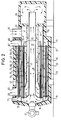
- Fig. 2 shows details this unit.
- the burner stage 19 has one related to yours Combustion chamber 37 of long diameter and enclosed by a tube 35, at one end of the burner 17 is arranged and with their other end opens into a buffer chamber 39.
- the heat exchanger stages 11, 25 enclose the tube 35 coaxially, the Heat exchanger stage 11, the heat exchanger stage 25 radially outside coaxially encloses.
- the heat exchanger stage 25 becomes radial inside by a pipe 35 enclosing it at a radial distance Pipe wall 41 and bounded radially outwards by a pipe wall 43.
- Tube walls 41, 43 extends approximately parallel to the Tube 35 and distributed in its circumferential direction and variety Exchanger tubes 45 at their end adjacent to burner 17 through an end wall that closes the pipe 35 to the pipe wall 43 47 and at its other end through an end wall 49 one this side adjoining the tubular wall 41 in a ring Pass through collecting space 51.
- the tube wall 41 forms the radially inner boundary of the collecting space 51 and leaves between himself and the tube 35 an annular heating gas guide chamber 53, the buffer chamber 39 with a burner 17 facing Inlet end one between the tube walls 41, 43 along the Exchanger tubes 45 extending heating gas guide chamber 55 connects.
- the collecting space 51 is adjacent in the tube wall 43 in A plurality of passage openings 57 distribute circumferentially provided through which the heating gases flow into a between the tube wall 43 and an outer wall 59 formed to the tube 35 coaxial heating gas guide chamber 61 can pass the heat exchanger stage 11.
- the Heating gas guide chamber 61 is through at its end on the burner side an end wall connecting the pipe wall 43 to the outer wall 59 63 completed and in the region of the end wall 63 with an outlet 65 provided.
- At the end of the buffer chamber is near the openings 57, but between them and the annular space 51, another End wall between the tube wall 43 and the outer wall 59 is provided.
- the end wall 67 delimits together with the tube wall 43 and the outer wall 59 a further one, provided with an outlet 69, annular collecting space 71.
- the heating gas guide chamber 61 extends a plurality distributed in the circumferential direction Exchanger tubes 73, which are similar to the exchanger tubes 45 with their open ends through the end walls 63, 67 and on the one hand in the collecting space 71 and on the other hand in an annular, through the tube wall 43, the outer wall 59 and the end wall 63 delimited Collection room 75 open out.
- the collecting space 75 is with an inlet opening 77 provided.
- An inlet opening leading through the housing wall 59 of the annular space 51 is shown at 79.
- heating gases are supplied via the inlet opening 79 and via the annular space 51 to the exchanger tubes 45 of the heat exchanger stage 25 distributed.
- the exchanger tubes 45 open in the area of the Brenners 17 in the combustion chamber 37, where they on the for thermal post-combustion required temperature, for example 750 ° C, are heated. To be sufficiently large and for thermal afterburning sufficient reaction time ensure that those at high temperature flow Heating gases in the direction of the arrows shown in Fig.
- Fig. 3 shows a variant of the system from Fig. 1, which is in differs primarily in that for cleaning the heating gases of odorous substances a catalytic combustion of the heating gases in a catalyst stage 81 is provided, which between the Burner stage 19a and the heat exchanger stage 11a in the heating gas path is inserted.
- the from the centrifugal separator 23a at the exit of the Roasters 1a released roast exhaust gases are in burner stage 19a to a heating gas heat level sufficient for catalytic combustion brought and then go through the catalyst stage 81, before the afterburning heat in the heat exchanger stage 11a for the generation of the roasting gases is recovered.
- the burner stage 19a, the catalyst stage 81 and the heat exchanger stage 11a can in the manner explained with reference to FIG. 2 can be combined into one unit, at least the Burner stage 19a and heat exchanger stage 11a are those explained there can have a coaxial structure.
- the catalyst stage 81 can axially next to the heat exchanger stage 11a or coaxially one above the other based on the heat exchanger stage 11a be arranged.
- the catalyst of the catalyst stage 81 can it is an oxidation catalyst that is suitable for a Dwell time of the heating gases between 0.05 and 0.1 seconds is at a reaction temperature between 320 ° C and 420 ° C.
- Fig. 4 shows a variant of the roasting plant, in which the burner stage 19b is designed as a combustor and the burner 17b in Pulse mode the roasting exhaust gases with burning pulses of about 0.1 Warmed to about 700 to 800 ° C for seconds.
- the burner stage 19b is designed as a combustor and the burner 17b in Pulse mode the roasting exhaust gases with burning pulses of about 0.1 Warmed to about 700 to 800 ° C for seconds.
- FIG. 4 still blower 83 at the entrance and exit of the combustor 19b and shown at the outlet of the centrifugal separator 15b.
- shunt lines 27b and 29b can also as shown at 85 in the heating gas path of the heat exchanger stage 11b a shunt line with one of the heat quantity regulation serving valve or a flap may be provided.
- the pulse burner 17b burns gas or oil essentially without residues, the combustion exhaust gases with the supplied roasting exhaust gases in the Combustor can be mixed.
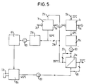
- Fig. 5 shows a variant of the roasting plant according to Fig. 4, in which additionally between the centrifugal separator 23c and the Fan burner 19c for oil or gas an adsorption filter 87 in the Flow path of the roasting exhaust gases, for example a filter on the Base of zeolite powder, is arranged.
- the burner 19c must so that the temperature level of the roasted exhaust gases only to that for the Raising the heat level of the cooling exhaust gases to the roasting gas heat level heat the required measure.
- the blower 83 and the shunt line 85 can also be provided here in the manner shown be.
- the cooling supply air can either be here the environment or from the exhaust air of a further processing stage, for example, a stone removal step.
Landscapes
- Life Sciences & Earth Sciences (AREA)
- Chemical & Material Sciences (AREA)
- Engineering & Computer Science (AREA)
- Food Science & Technology (AREA)
- Polymers & Plastics (AREA)
- Apparatuses For Bulk Treatment Of Fruits And Vegetables And Apparatuses For Preparing Feeds (AREA)
- Tea And Coffee (AREA)
Description
Claims (19)
- Anordnung zum Rösten von pflanzlichem Schüttgut, insbesondere Kaffeebohnen, umfassendeine Heizeinrichtung (11, 17, 19, 25) zur Erzeugung eines Röstgasstroms,eine das Schüttgut in dem Röstgasstrom röstende Rösteinrichtung (1),eine das geröstete Schüttgut aus der Rösteinrichtung (1) aufnehmende und in einem Kühlgasstrom kühlende Kühleinrichtung (7), die zumindest einen Teil ihrer Kühlgase an die Heizeinrichtung (11,17, 19, 25) abgibt,
dadurch gekennzeichnet, daß die Heizeinrichtung (11, 17, 19, 25) eine durch Heizgase zu speisende Wärmetauscherstufe (11) umfaßt, die den Wärmeinhalt im wesentlichen der gesamten, von der Kühleinrichtung (7) abgegebenen Kühlgase für die Erzeugung der Röstgase auf ein das Rösten des Schüttguts erlaubendes Wärmeniveau erhöht und als Röstgas an die Rösteinrichtung (1) abgibt. - Anordnung nach Anspruch 1, dadurch gekennzeichnet, daß die Temperatur der von der Wärmetauscherstufe (11) abgegebenen Röstgase zwischen 290°C und 390°C, insbesondere zwischen 300°C und 360°C, liegt.
- Anordnung nach Anspruch 1 oder 2, dadurch gekennzeichnet, daß im Kühlgasweg zwischen der Kühleinrichtung (7) und der den Wärmeinhalt der Kühlgase auf Röstgas-Wärmeniveau hebenden Wärmetauscherstufe (11) eine Gasreinigungsstufe (15) angeordnet ist.
- Anordnung nach einem der Ansprüche 1 bis 3, dadurch gekennzeichnet, daß die Heizeinrichtung (11, 17, 19, 25) ferner eine Heizstufe (19) umfaßt, die den Wärmeinhalt im wesentlichen der gesamten von der Rösteinrichtung (1) abgegebenen Röstgase über das Röstgas-Wärmeniveau hinaus erhöht und als Heizgas an die Wärmetauscherstufe (11) abgibt.
- Anordnung nach Anspruch 4, dadurch gekennzeichnet, daß die Heizstufe als die Röstgase einer Schadstoffverbrennung unterziehende Brennerstufe (19; 19b) ausgebildet ist.
- Anordnung nach Anspruch 5, dadurch gekennzeichnet, daß die Brennerstufe (19b) einen Gas- oder Öl-Impulsbrenner (17b) umfaßt.
- Anordnung nach einem der Ansprüche 4 bis 6, dadurch gekennzeichnet, daß im Heizgasweg zwischen der Heizstufe (19a) und der dem Wärmeinhalt der Kühlgase auf Röstgas-Wärmeniveau hebenden Wärmetauscherstufe (11a) eine das Heizgas oxidationskatalytisch reinigende Gasreinigungsstufe (81) angeordnet ist.
- Anordnung nach einem der Ansprüche 4 bis 7, dadurch gekennzeichnet, daß im Röstgasweg zwischen der Rösteinrichtung (1) und der Heizstufe (19) eine Gasreinigungsstufe (23) angeordnet ist.
- Anordnung nach einem der Ansprüche 1 bis 8, dadurch gekennzeichnet, daß Mittel (19; 81; 87) zur Adsorptionsreinigung oder/und thermischen Reinigung oder/und katalytischen Reinigung der Röstgase oder/und Heizgase vorgesehen sind.
- Anordnung nach einem der Ansprüche 1 bis 9, dadurch gekennzeichnet, daß im Röstgasweg ein Adsorptionsfilter (87) angeordnet ist.
- Anordnung nach einem der Ansprüche 4 bis 10, dadurch gekennzeichnet, daß die Heizeinrichtung (11, 17, 19, 25) eine weitere, durch die Heizgase der Heizstufe zu speisende Wärmetauscherstufe (25) umfaßt, die den Wärmeinhalt im wesentlichen der gesamten, von der Rösteinrichtung (1) an die Heizstufe (19) abgegebenen Röstgase erhöht.
- Anordnung nach Anspruch 11, dadurch gekennzeichnet, daß die Heizstufe (19) und die Wärmetauscherstufen (11, 25) zu einer Baueinheit zusammengefaßt sind, in der die Wärmetauscherstufen (11, 25) zueinander koaxial eine zentrale, an einem Ende an einen Brenner (17), insbesondere Gas- oder Ölbrenner, anschließende, rohrförmige Brennkammer (37) umschließen.
- Anordnung nach Anspruch 12, dadurch gekennzeichnet, daß die Wärmetauscherstufen (11, 25) ringraumförmige, die Brennkammer (37) umschließende Heizgas-Führungskammern (55, 61) umfassen, in welchen eine Vielzahl im wesentlichen längs der Brennkammer (37) sich erstreckende und an ihren Enden in ringförmigen Sammelräumen (51, 71, 75) mündende Rohre (45, 73) für die Führung der Kühl- bzw. Röstgase angeordnet sind.
- Anordnung nach Anspruch 13, dadurch gekennzeichnet, daß die Brennkammer (37) und die Heizgas-Führungskammern (55, 61) einen seriellen Strömungsweg für die Heizgase bilden.
- Anordnung nach Anspruch 13 oder 14, dadurch gekennzeichnet,daß die Kühlgase oder/und die Röstgase die Rohre (45, 73) entgegen der Strömungsrichtung der Heizgase in der Heizgas-Führungskammer (55, 61) durchströmen.
- Anordnung nach einem der Ansprüche 12 bis 15, dadurch gekennzeichnet, daß die die Kühlgase auf Röstgas-Wärmeniveau erwärmende Wärmetauscherstufe (11) die weitere Wärmetauscherstufe (25) radial außen umschließt.
- Anordnung nach einem der Ansprüche 12 bis 16, dadurch gekennzeichnet, daß das dem Brenner (17) abgewandte Ende der Brennkammer (37) in einer Pufferkammer (39) mündet.
- Anordnung nach einem der Ansprüche 1 bis 17, dadurch gekennzeichnet, daß zumindest die den Wärmeinhalt der Kühlgase auf Röstgas-Wärmeniveau anhebende Wärmetauscherstufe (11) im Kühlgasweg oder/und im Heizgasweg durch eine Nebenschlußleitung (27; 85) mit steuerbarem Durchflußquerschnitt überbrückt ist.
- Anordnung nach einem der Ansprüche 1 bis 18, dadurch gekennzeichnet, daß der Kühleinrichtung (7) Abluft einer weiteren Verarbeitungsstufe, insbesondere einer Entsteinungsstufe (33) als Kühlluft zuführbar ist.
Applications Claiming Priority (2)
| Application Number | Priority Date | Filing Date | Title |
|---|---|---|---|
| DE19520228A DE19520228A1 (de) | 1995-06-01 | 1995-06-01 | Anordnung zum Rösten von pflanzlichem Schüttgut, insbesondere Kaffeebohnen |
| DE19520228 | 1995-06-01 |
Publications (2)
| Publication Number | Publication Date |
|---|---|
| EP0745334A1 EP0745334A1 (de) | 1996-12-04 |
| EP0745334B1 true EP0745334B1 (de) | 1998-01-07 |
Family
ID=7763485
Family Applications (1)
| Application Number | Title | Priority Date | Filing Date |
|---|---|---|---|
| EP96108626A Expired - Lifetime EP0745334B1 (de) | 1995-06-01 | 1996-05-30 | Anordnung zum Rösten von pflanzlichem Schüttgut, insbesondere Kaffeebohnen |
Country Status (7)
| Country | Link |
|---|---|
| US (1) | US5718164A (de) |
| EP (1) | EP0745334B1 (de) |
| JP (1) | JPH08322533A (de) |
| AT (1) | ATE161692T1 (de) |
| DE (2) | DE19520228A1 (de) |
| DK (1) | DK0745334T3 (de) |
| ES (1) | ES2114753T3 (de) |
Families Citing this family (28)
| Publication number | Priority date | Publication date | Assignee | Title |
|---|---|---|---|---|
| US5946815A (en) * | 1997-12-18 | 1999-09-07 | Wetzel; Clifford C. | Apparatus for roasting legumes |
| US6090423A (en) * | 1997-12-18 | 2000-07-18 | Wetzel; Clifford C. | Method for roasting legumes |
| US5996480A (en) * | 1998-08-14 | 1999-12-07 | Hearthware Home Products, Inc. | Apparatus for roasting coffee beans |
| US6173506B1 (en) | 1999-04-29 | 2001-01-16 | Premark Wb Holdings, Inc. | Roaster |
| US6558726B2 (en) | 2001-09-28 | 2003-05-06 | The Metal Ware Corporation | Coffee bean roasting apparatus |
| DE10156887C1 (de) * | 2001-11-20 | 2003-04-17 | Gimborn Probat Werke | Verfahren zum Rösten von schüttfähigen Lebensmitteln mit Heißluft sowie Vorrichtung zur Durchführung desselben |
| US20050132893A1 (en) * | 2003-12-17 | 2005-06-23 | Kraft Foods Holdings, Inc. | Process for single-stage heat treatment and grinding of coffee beans |
| US20060029703A1 (en) * | 2004-08-06 | 2006-02-09 | Kraft Foods Holdings, Inc. | Process for single-stage heat treatment and grinding of mustard bran, and product and its uses |
| US20060040027A1 (en) * | 2004-08-17 | 2006-02-23 | Kraft Foods Holdings, Inc. | Process for manufacture of grated cheese and uses thereof |
| US7445806B2 (en) * | 2004-09-02 | 2008-11-04 | Kraft Foods Global Brands Llc | Process for selective grinding and recovery of dual-density foods |
| CA2582376C (en) * | 2004-10-01 | 2014-04-29 | Canmar Grain Products Ltd. | Methods for roasting oil seed, and roasted oil seed products |
| US20060083834A1 (en) * | 2004-10-14 | 2006-04-20 | Kraft Foods Holdings, Inc. | Process for granulation of wet processed foods and use thereof |
| US20060088634A1 (en) * | 2004-10-25 | 2006-04-27 | Kraft Foods Holdings, Inc. | Process for granulation of low-moisture processed foods and use thereof |
| US20060286230A1 (en) * | 2005-06-15 | 2006-12-21 | Kraft Foods Holdings, Inc. | Process for packing separation and granulation of processed food content thereof, and products and uses thereof |
| US20060286232A1 (en) * | 2005-06-15 | 2006-12-21 | Kraft Foods Holdings, Inc. | Process for granulation of low-moisture, high-lipid content processed foods and re-use thereof |
| US20060286269A1 (en) * | 2005-06-16 | 2006-12-21 | Kraft Foods Holdings, Inc. | Process for granulation of edible seeds |
| US20060286246A1 (en) * | 2005-06-16 | 2006-12-21 | Kraft Foods Holdings, Inc. | Preparation of bakery mixes |
| US8067051B2 (en) * | 2006-06-19 | 2011-11-29 | Kraft Foods R & D, Inc. | Process for milling cocoa shells |
| DE102007006268B3 (de) * | 2007-02-08 | 2008-05-29 | Probat-Werke Von Gimborn Maschinenfabrik Gmbh | Vorrichtung und Verfahren zur Wärmebehandlung eines schüttfähigen pflanzlichen Gutes |
| GB2482032B (en) | 2010-07-16 | 2013-04-10 | Kraft Foods R & D Inc | Coffee products and related processes |
| US9392807B2 (en) | 2012-01-16 | 2016-07-19 | New Roast Coffee Holdings Llc | Method of manufacturing partially roasted coffee beans and a combination roasting and brewing device |
| AT513829B1 (de) * | 2013-08-28 | 2014-08-15 | Steiner Johann | Sojatoastanlage |
| EP3230671B2 (de) * | 2014-12-08 | 2022-04-27 | Stela Laxhuber GmbH | Trocknungsanlage mit einem trocknungsbereich |
| US10143205B2 (en) * | 2015-01-26 | 2018-12-04 | Guy E. Buller-Colthurst | Air stream manipulation within a thermal processing oven |
| CN110268567B (zh) * | 2017-02-09 | 2022-10-18 | Avl李斯特有限公司 | 用于燃料电池系统的启动燃烧器 |
| US10602764B2 (en) | 2017-04-13 | 2020-03-31 | Bellwether Coffee Co. | Roasting system with clean emissions and high thermal efficiency |
| US10362798B2 (en) | 2017-04-13 | 2019-07-30 | Bellwether Coffee Co. | Roasting system with clean emissions and high thermal efficiency |
| EP3598903B1 (de) * | 2018-07-26 | 2020-12-09 | ReiCat GmbH | Röstanlage zum rösten von lebensmittelprodukten und verfahren zum betreiben einer röstanlage zum rösten von lebensmittelprodukten |
Family Cites Families (34)
| Publication number | Priority date | Publication date | Assignee | Title |
|---|---|---|---|---|
| DE1729425C3 (de) * | 1968-03-07 | 1978-03-16 | Maschinenfabrik Ferd. Gothot Gmbh, 4330 Muelheim | Vorrichtung zum chargenweisen Rösten von körnigem Gut |
| NL165045C (nl) * | 1971-01-05 | Gimborn Probat Werke | Inrichting voor een warmte-, koude- en/of stof- behandeling van korrelig vloeibaar materiaal. | |
| DE2103281C3 (de) * | 1971-01-25 | 1981-09-10 | Probat-Werke Von Gimborn Gmbh & Co Kg, 4240 Emmerich | Einrichtung zur Wärme-, Kälte und/oder Stoffbehandlung |
| DE2207803A1 (de) * | 1972-02-18 | 1973-08-23 | Gimborn Probat Werke | Roestverfahren und roestmaschine zu dessen durchfuehrung |
| DE2354780B2 (de) * | 1973-11-02 | 1980-02-14 | Fabrik Fuer Pat. Sicherheits-Roester G.W. Barth Ludwigsburg, 7140 Ludwigsburg | Röstverfahren und Röstmaschine zu dessen Durchführung |
| US3841826A (en) * | 1974-01-30 | 1974-10-15 | Blaw Knox Food Chemical | Process and apparatus for continuously roasting bean-like materials |
| DE2424142C3 (de) * | 1974-05-17 | 1981-02-12 | Probat-Werke Von Gimborn Gmbh & Co Kg, 4240 Emmerich | Verfahren zum Trocknen und Rösten von Kaffee, Kakao und Malz oder eines anderen rieselfähigen Produkts |
| GB1530784A (en) * | 1975-05-29 | 1978-11-01 | Dej Int Research Co Bv | Process for the roasting of coffee |
| CH609214A5 (en) * | 1976-10-05 | 1979-02-28 | Escher Wyss Gmbh | Gravity drier for free-flowing material, in particular seed kernels |
| DE2855492A1 (de) * | 1978-12-22 | 1980-07-03 | Buehler Miag Gmbh | Verfahren und trockner zum kontinuierlichen trocknen von getreide o.ae. rieselfaehigen gut |
| US4425720A (en) * | 1981-03-05 | 1984-01-17 | Elevitch Franklin R | Coffee roaster |
| DE3116723C2 (de) * | 1981-04-28 | 1984-11-29 | NEOTEC Gesellschaft für Nahrungsmittelverfahrenstechnik mbH & Co KG, 2000 Norderstedt | Vorrichtung zum Wirbelschicht-Rösten und anschließenden Kühlen von kleinstückigen Naturprodukten, insbesondere Kaffeebohnen |
| IT1158395B (it) * | 1982-06-08 | 1987-02-18 | Vittoria Spa Off | Impianto automatico e ad elevata resa termica per la tostatura del caffe' o di altri prodotti |
| US4494314A (en) * | 1983-11-28 | 1985-01-22 | Gell Jr Harold A | Coffee roaster |
| DE3430103A1 (de) * | 1984-08-16 | 1986-02-27 | Tchibo Frisch-Röst-Kaffee AG, 2000 Hamburg | Verfahren zum roesten von kaffee mittels eines laden-kleinroesters |
| DE3604808C1 (de) * | 1986-02-15 | 1987-08-06 | Nordischer Maschinenbau | Vorrichtung zur kontinuierlichen Garung und/oder Entwaesserung von Nahrungsmitteln |
| DE3605415A1 (de) * | 1986-02-20 | 1987-08-27 | Katec Betz Gmbh & Co | Verfahren und vorrichtung zum verbrennen oxidierbarer bestandteile in einem traegergas |
| DE3711098A1 (de) * | 1987-04-02 | 1988-10-13 | Tchibo Frisch Roest Kaffee Ag | Kleinportionen-kaffeeroester |
| DE3714594C2 (de) * | 1987-04-28 | 1995-01-05 | Novopack Maschinenbau Gmbh | Kaffeebohnenröster |
| EP0314827A1 (de) * | 1987-11-03 | 1989-05-10 | Probat-Werke von Gimborn GmbH & Co. KG | Verfahren zum Kühlen vn röstheissem, körnigem, rieselfähigem Gut |
| JPH0272828A (ja) * | 1988-03-10 | 1990-03-13 | Isamu Miya | 珈琲豆の簡易焙煎方法 |
| EP0470254A4 (en) * | 1989-12-21 | 1992-07-15 | Kabushiki Kaisha Doutor Coffee | Device for roasting coffee beans |
| DE4028112A1 (de) * | 1990-09-05 | 1992-03-12 | Tchibo Frisch Roest Kaffee | Verfahren und vorrichtung zum vermindern von schadstoffen in der abluft bei der kuehlung von roestkaffee oder aehnlichen roestprodukten mit luft |
| DE4028111A1 (de) * | 1990-09-05 | 1992-03-12 | Tchibo Frisch Roest Kaffee | Verfahren zum kuehlen und befeuchten von geroesteten kaffeebohnen oder aehnlichen grobteiligen roestprodukten sowie hierfuer geeignete vorrichtung |
| US5230281A (en) * | 1991-07-10 | 1993-07-27 | Blaw Knox Food & Chemical Equipment Co. | Apparatus for roasting coffee beans or the like |
| US5269072A (en) * | 1992-05-22 | 1993-12-14 | Felknor International | Coffee roaster |
| EP0578902A1 (de) * | 1992-07-17 | 1994-01-19 | PETRONCINI SpA | Röstsystem |
| US5386764A (en) * | 1993-07-27 | 1995-02-07 | Ratajczek; William J. | Grain roaster/cooler with preheater |
| US5394623A (en) * | 1993-10-12 | 1995-03-07 | Sewell; Richard C. | Fluidized bed coffee roaster |
| US5359788A (en) * | 1993-12-22 | 1994-11-01 | Gell Jr Harold A | Coffee roaster |
| US5564331A (en) * | 1994-11-03 | 1996-10-15 | Imex Corporation Ltd. | Apparatus for roasting coffee beans |
| US5573802A (en) * | 1995-03-14 | 1996-11-12 | The Hugo Gepo Co., Inc. | Coffee roaster oven chamber |
| US5609097A (en) * | 1995-04-24 | 1997-03-11 | Newnan; Brian D. | Coffee bean roaster with visual display column |
| US5638607A (en) * | 1995-11-08 | 1997-06-17 | Source Intermarketing Ag | Coffee roaster |
-
1995
- 1995-06-01 DE DE19520228A patent/DE19520228A1/de not_active Withdrawn
-
1996
- 1996-05-30 EP EP96108626A patent/EP0745334B1/de not_active Expired - Lifetime
- 1996-05-30 DE DE59600068T patent/DE59600068D1/de not_active Expired - Fee Related
- 1996-05-30 ES ES96108626T patent/ES2114753T3/es not_active Expired - Lifetime
- 1996-05-30 DK DK96108626T patent/DK0745334T3/da active
- 1996-05-30 AT AT96108626T patent/ATE161692T1/de not_active IP Right Cessation
- 1996-05-31 US US08/656,482 patent/US5718164A/en not_active Expired - Fee Related
- 1996-06-03 JP JP8162423A patent/JPH08322533A/ja not_active Withdrawn
Also Published As
| Publication number | Publication date |
|---|---|
| ATE161692T1 (de) | 1998-01-15 |
| JPH08322533A (ja) | 1996-12-10 |
| ES2114753T3 (es) | 1998-06-01 |
| DE59600068D1 (de) | 1998-02-12 |
| DK0745334T3 (da) | 1998-09-07 |
| US5718164A (en) | 1998-02-17 |
| DE19520228A1 (de) | 1996-12-05 |
| EP0745334A1 (de) | 1996-12-04 |
Similar Documents
| Publication | Publication Date | Title |
|---|---|---|
| EP0745334A1 (de) | Anordnung zum Rösten von pflanzlichem Schüttgut, insbesondere Kaffeebohnen | |
| DE3447079C2 (de) | ||
| DE69526659T2 (de) | Wandstrahlungsofen und verfahren zum zubereiten eines nahrungsmittels | |
| DE2746330C2 (de) | Verfahren und Vorrichtung zum Brennen von Sintermaterial | |
| DE2732588C2 (de) | ||
| AT401420B (de) | Einrichtung zur verfeuerung von biomasse | |
| AT397860B (de) | Anlage zum trocknen von drehabfällen bzw. von metallischem oder nichtmetallischem schrott vor dem einführen in schmelzöfen | |
| EP1138212A2 (de) | Röstvorrichtung | |
| DE8413119U1 (de) | Rauchgasverbrennungsofen fuer eine brennbare abgase produzierende verarbeitungsanlage | |
| DE3141484C2 (de) | ||
| DE3504950C2 (de) | ||
| CH667372A5 (de) | Schaelverfahren fuer bohnenartige fruechte und vorrichtung zur durchfuehrung des verfahrens. | |
| DE2851005C2 (de) | Verfahren und Vorrichtung zum Trocknen von Schlamm | |
| DE3447481A1 (de) | Bratroehre mit selbsttaetiger beseitigung von geruchs- u. verschmutzungsteilchen in der bratroehrenluft | |
| DE4023432C2 (de) | Tunnelofen | |
| DE3728487C2 (de) | Verfahren zur pyrolytischen Behandlung von Abfall- oder Schadstoffen | |
| DE3711098C2 (de) | ||
| EP3598903B1 (de) | Röstanlage zum rösten von lebensmittelprodukten und verfahren zum betreiben einer röstanlage zum rösten von lebensmittelprodukten | |
| DE886013C (de) | Durchlaufofen und Verfahren zu seinem Betrieb | |
| DE3235261A1 (de) | Verfahren und einrichtung zur nutzung der abwaerme und zur gewinnung von wassergas beim kuehlen von koks | |
| DE102007039273A1 (de) | Feststoffbrenner und Verfahrensweise seiner Kühlung | |
| EP0704161A2 (de) | Entkeimung von pflanzlichen Produkten | |
| DE1779413C3 (de) | Warmeruckgewinnungsvorrichtung fur Trockner mit katalytischer Verbrennung der Abgase | |
| DE2513116A1 (de) | Vorrichtung zur verbrennung von abgasen | |
| DE2357630C3 (de) | Anlage zur Aufbereitung von Abfallprodukten |
Legal Events
| Date | Code | Title | Description |
|---|---|---|---|
| PUAI | Public reference made under article 153(3) epc to a published international application that has entered the european phase |
Free format text: ORIGINAL CODE: 0009012 |
|
| AK | Designated contracting states |
Kind code of ref document: A1 Designated state(s): AT BE CH DE DK ES FR GB IT LI NL PT SE |
|
| 17P | Request for examination filed |
Effective date: 19961210 |
|
| GRAG | Despatch of communication of intention to grant |
Free format text: ORIGINAL CODE: EPIDOS AGRA |
|
| 17Q | First examination report despatched |
Effective date: 19970603 |
|
| GRAG | Despatch of communication of intention to grant |
Free format text: ORIGINAL CODE: EPIDOS AGRA |
|
| GRAH | Despatch of communication of intention to grant a patent |
Free format text: ORIGINAL CODE: EPIDOS IGRA |
|
| GRAH | Despatch of communication of intention to grant a patent |
Free format text: ORIGINAL CODE: EPIDOS IGRA |
|
| GRAA | (expected) grant |
Free format text: ORIGINAL CODE: 0009210 |
|
| AK | Designated contracting states |
Kind code of ref document: B1 Designated state(s): AT BE CH DE DK ES FR GB IT LI NL PT SE |
|
| REF | Corresponds to: |
Ref document number: 161692 Country of ref document: AT Date of ref document: 19980115 Kind code of ref document: T |
|
| ITF | It: translation for a ep patent filed | ||
| REG | Reference to a national code |
Ref country code: CH Ref legal event code: NV Representative=s name: A. BRAUN, BRAUN, HERITIER, ESCHMANN AG PATENTANWAE Ref country code: CH Ref legal event code: EP |
|
| GBT | Gb: translation of ep patent filed (gb section 77(6)(a)/1977) |
Effective date: 19980108 |
|
| REF | Corresponds to: |
Ref document number: 59600068 Country of ref document: DE Date of ref document: 19980212 |
|
| PGFP | Annual fee paid to national office [announced via postgrant information from national office to epo] |
Ref country code: SE Payment date: 19980309 Year of fee payment: 3 |
|
| PGFP | Annual fee paid to national office [announced via postgrant information from national office to epo] |
Ref country code: AT Payment date: 19980324 Year of fee payment: 3 |
|
| PGFP | Annual fee paid to national office [announced via postgrant information from national office to epo] |
Ref country code: PT Payment date: 19980330 Year of fee payment: 3 |
|
| ET | Fr: translation filed | ||
| PGFP | Annual fee paid to national office [announced via postgrant information from national office to epo] |
Ref country code: BE Payment date: 19980513 Year of fee payment: 3 |
|
| PGFP | Annual fee paid to national office [announced via postgrant information from national office to epo] |
Ref country code: DK Payment date: 19980528 Year of fee payment: 3 |
|
| PGFP | Annual fee paid to national office [announced via postgrant information from national office to epo] |
Ref country code: ES Payment date: 19980529 Year of fee payment: 3 |
|
| REG | Reference to a national code |
Ref country code: ES Ref legal event code: FG2A Ref document number: 2114753 Country of ref document: ES Kind code of ref document: T3 |
|
| REG | Reference to a national code |
Ref country code: PT Ref legal event code: SC4A Free format text: AVAILABILITY OF NATIONAL TRANSLATION Effective date: 19980330 |
|
| REG | Reference to a national code |
Ref country code: DK Ref legal event code: T3 |
|
| PLBE | No opposition filed within time limit |
Free format text: ORIGINAL CODE: 0009261 |
|
| STAA | Information on the status of an ep patent application or granted ep patent |
Free format text: STATUS: NO OPPOSITION FILED WITHIN TIME LIMIT |
|
| 26N | No opposition filed | ||
| PG25 | Lapsed in a contracting state [announced via postgrant information from national office to epo] |
Ref country code: AT Free format text: LAPSE BECAUSE OF NON-PAYMENT OF DUE FEES Effective date: 19990530 |
|
| PG25 | Lapsed in a contracting state [announced via postgrant information from national office to epo] |
Ref country code: SE Free format text: LAPSE BECAUSE OF NON-PAYMENT OF DUE FEES Effective date: 19990531 Ref country code: ES Free format text: LAPSE BECAUSE OF NON-PAYMENT OF DUE FEES Effective date: 19990531 Ref country code: DK Free format text: LAPSE BECAUSE OF NON-PAYMENT OF DUE FEES Effective date: 19990531 Ref country code: BE Free format text: LAPSE BECAUSE OF NON-PAYMENT OF DUE FEES Effective date: 19990531 |
|
| BERE | Be: lapsed |
Owner name: PROBAT-WERKE VON GIMBORN MASCHINENFABRIK G.M.B.H. Effective date: 19990531 |
|
| PG25 | Lapsed in a contracting state [announced via postgrant information from national office to epo] |
Ref country code: PT Free format text: LAPSE BECAUSE OF NON-PAYMENT OF DUE FEES Effective date: 19991130 |
|
| EUG | Se: european patent has lapsed |
Ref document number: 96108626.1 |
|
| REG | Reference to a national code |
Ref country code: PT Ref legal event code: MM4A Free format text: LAPSE DUE TO NON-PAYMENT OF FEES Effective date: 19991130 |
|
| REG | Reference to a national code |
Ref country code: DK Ref legal event code: EBP |
|
| REG | Reference to a national code |
Ref country code: ES Ref legal event code: FD2A Effective date: 20010503 |
|
| REG | Reference to a national code |
Ref country code: GB Ref legal event code: IF02 |
|
| PGFP | Annual fee paid to national office [announced via postgrant information from national office to epo] |
Ref country code: DE Payment date: 20020215 Year of fee payment: 7 |
|
| PGFP | Annual fee paid to national office [announced via postgrant information from national office to epo] |
Ref country code: FR Payment date: 20020315 Year of fee payment: 7 |
|
| PGFP | Annual fee paid to national office [announced via postgrant information from national office to epo] |
Ref country code: GB Payment date: 20020423 Year of fee payment: 7 |
|
| PGFP | Annual fee paid to national office [announced via postgrant information from national office to epo] |
Ref country code: NL Payment date: 20020531 Year of fee payment: 7 |
|
| PGFP | Annual fee paid to national office [announced via postgrant information from national office to epo] |
Ref country code: CH Payment date: 20020619 Year of fee payment: 7 |
|
| PG25 | Lapsed in a contracting state [announced via postgrant information from national office to epo] |
Ref country code: GB Free format text: LAPSE BECAUSE OF NON-PAYMENT OF DUE FEES Effective date: 20030530 |
|
| PG25 | Lapsed in a contracting state [announced via postgrant information from national office to epo] |
Ref country code: LI Free format text: LAPSE BECAUSE OF NON-PAYMENT OF DUE FEES Effective date: 20030531 Ref country code: CH Free format text: LAPSE BECAUSE OF NON-PAYMENT OF DUE FEES Effective date: 20030531 |
|
| PG25 | Lapsed in a contracting state [announced via postgrant information from national office to epo] |
Ref country code: NL Free format text: LAPSE BECAUSE OF NON-PAYMENT OF DUE FEES Effective date: 20031201 |
|
| PG25 | Lapsed in a contracting state [announced via postgrant information from national office to epo] |
Ref country code: DE Free format text: LAPSE BECAUSE OF NON-PAYMENT OF DUE FEES Effective date: 20031202 |
|
| REG | Reference to a national code |
Ref country code: CH Ref legal event code: PL |
|
| GBPC | Gb: european patent ceased through non-payment of renewal fee |
Effective date: 20030530 |
|
| PG25 | Lapsed in a contracting state [announced via postgrant information from national office to epo] |
Ref country code: FR Free format text: LAPSE BECAUSE OF NON-PAYMENT OF DUE FEES Effective date: 20040130 |
|
| NLV4 | Nl: lapsed or anulled due to non-payment of the annual fee |
Effective date: 20031201 |
|
| REG | Reference to a national code |
Ref country code: FR Ref legal event code: ST |
|
| PG25 | Lapsed in a contracting state [announced via postgrant information from national office to epo] |
Ref country code: IT Free format text: LAPSE BECAUSE OF NON-PAYMENT OF DUE FEES;WARNING: LAPSES OF ITALIAN PATENTS WITH EFFECTIVE DATE BEFORE 2007 MAY HAVE OCCURRED AT ANY TIME BEFORE 2007. THE CORRECT EFFECTIVE DATE MAY BE DIFFERENT FROM THE ONE RECORDED. Effective date: 20050530 |