EP0744672A1 - Bilderzeugungsgerät und Zwischenübertragungselement - Google Patents
Bilderzeugungsgerät und Zwischenübertragungselement Download PDFInfo
- Publication number
- EP0744672A1 EP0744672A1 EP96303593A EP96303593A EP0744672A1 EP 0744672 A1 EP0744672 A1 EP 0744672A1 EP 96303593 A EP96303593 A EP 96303593A EP 96303593 A EP96303593 A EP 96303593A EP 0744672 A1 EP0744672 A1 EP 0744672A1
- Authority
- EP
- European Patent Office
- Prior art keywords
- toner
- image
- intermediate transfer
- transfer
- transfer member
- Prior art date
- Legal status (The legal status is an assumption and is not a legal conclusion. Google has not performed a legal analysis and makes no representation as to the accuracy of the status listed.)
- Granted
Links
- 238000012546 transfer Methods 0.000 title claims abstract description 533
- 239000000463 material Substances 0.000 claims abstract description 47
- 238000000034 method Methods 0.000 claims description 112
- 239000002245 particle Substances 0.000 claims description 96
- 229920005989 resin Polymers 0.000 claims description 20
- 239000011347 resin Substances 0.000 claims description 20
- 230000000694 effects Effects 0.000 claims description 17
- YCKRFDGAMUMZLT-UHFFFAOYSA-N Fluorine atom Chemical compound [F] YCKRFDGAMUMZLT-UHFFFAOYSA-N 0.000 claims description 13
- 239000011737 fluorine Substances 0.000 claims description 13
- 229910052731 fluorine Inorganic materials 0.000 claims description 13
- 238000011161 development Methods 0.000 claims description 11
- 230000015572 biosynthetic process Effects 0.000 claims description 4
- 238000005755 formation reaction Methods 0.000 claims 1
- 238000004140 cleaning Methods 0.000 description 203
- 230000008569 process Effects 0.000 description 91
- 239000010410 layer Substances 0.000 description 71
- 230000001788 irregular Effects 0.000 description 33
- 239000002344 surface layer Substances 0.000 description 29
- 229920000642 polymer Polymers 0.000 description 27
- 230000003578 releasing effect Effects 0.000 description 22
- 238000002474 experimental method Methods 0.000 description 19
- VYPSYNLAJGMNEJ-UHFFFAOYSA-N Silicium dioxide Chemical compound O=[Si]=O VYPSYNLAJGMNEJ-UHFFFAOYSA-N 0.000 description 14
- 239000011230 binding agent Substances 0.000 description 14
- 238000010298 pulverizing process Methods 0.000 description 12
- 229910052782 aluminium Inorganic materials 0.000 description 10
- XAGFODPZIPBFFR-UHFFFAOYSA-N aluminium Chemical compound [Al] XAGFODPZIPBFFR-UHFFFAOYSA-N 0.000 description 10
- 150000001875 compounds Chemical class 0.000 description 9
- 229920001971 elastomer Polymers 0.000 description 9
- 230000005684 electric field Effects 0.000 description 9
- 229920002725 thermoplastic elastomer Polymers 0.000 description 9
- 238000007639 printing Methods 0.000 description 8
- 239000003921 oil Substances 0.000 description 7
- 239000004417 polycarbonate Substances 0.000 description 7
- 229920000515 polycarbonate Polymers 0.000 description 7
- 239000000377 silicon dioxide Substances 0.000 description 7
- -1 stainless steel Chemical compound 0.000 description 7
- 239000004809 Teflon Substances 0.000 description 6
- 229920006362 Teflon® Polymers 0.000 description 6
- 238000004519 manufacturing process Methods 0.000 description 6
- 229920000459 Nitrile rubber Polymers 0.000 description 5
- 230000006872 improvement Effects 0.000 description 5
- 229920000728 polyester Polymers 0.000 description 5
- 239000005060 rubber Substances 0.000 description 5
- ICIAVYAZISCZKY-XNOMRPDFSA-N (z)-2-butylbut-2-enedioic acid;butyl prop-2-enoate;styrene Chemical compound C=CC1=CC=CC=C1.CCCCOC(=O)C=C.CCCC\C(C(O)=O)=C\C(O)=O ICIAVYAZISCZKY-XNOMRPDFSA-N 0.000 description 4
- XEEYBQQBJWHFJM-UHFFFAOYSA-N Iron Chemical compound [Fe] XEEYBQQBJWHFJM-UHFFFAOYSA-N 0.000 description 4
- PPBRXRYQALVLMV-UHFFFAOYSA-N Styrene Chemical compound C=CC1=CC=CC=C1 PPBRXRYQALVLMV-UHFFFAOYSA-N 0.000 description 4
- 239000003086 colorant Substances 0.000 description 4
- 230000000052 comparative effect Effects 0.000 description 4
- 239000000806 elastomer Substances 0.000 description 4
- SZVJSHCCFOBDDC-UHFFFAOYSA-N iron(II,III) oxide Inorganic materials O=[Fe]O[Fe]O[Fe]=O SZVJSHCCFOBDDC-UHFFFAOYSA-N 0.000 description 4
- 239000000696 magnetic material Substances 0.000 description 4
- 238000005259 measurement Methods 0.000 description 4
- 230000003287 optical effect Effects 0.000 description 4
- 230000002093 peripheral effect Effects 0.000 description 4
- 230000035939 shock Effects 0.000 description 4
- 239000007787 solid Substances 0.000 description 4
- 238000012360 testing method Methods 0.000 description 4
- OKTJSMMVPCPJKN-UHFFFAOYSA-N Carbon Chemical compound [C] OKTJSMMVPCPJKN-UHFFFAOYSA-N 0.000 description 3
- 239000004697 Polyetherimide Substances 0.000 description 3
- 239000000956 alloy Substances 0.000 description 3
- 229910052799 carbon Inorganic materials 0.000 description 3
- 239000004020 conductor Substances 0.000 description 3
- 229920001577 copolymer Polymers 0.000 description 3
- 230000001419 dependent effect Effects 0.000 description 3
- NBVXSUQYWXRMNV-UHFFFAOYSA-N fluoromethane Chemical compound FC NBVXSUQYWXRMNV-UHFFFAOYSA-N 0.000 description 3
- 239000007788 liquid Substances 0.000 description 3
- 229920001601 polyetherimide Polymers 0.000 description 3
- 239000010935 stainless steel Substances 0.000 description 3
- 229910001220 stainless steel Inorganic materials 0.000 description 3
- 238000010558 suspension polymerization method Methods 0.000 description 3
- XLYOFNOQVPJJNP-UHFFFAOYSA-N water Substances O XLYOFNOQVPJJNP-UHFFFAOYSA-N 0.000 description 3
- PAYRUJLWNCNPSJ-UHFFFAOYSA-N Aniline Chemical compound NC1=CC=CC=C1 PAYRUJLWNCNPSJ-UHFFFAOYSA-N 0.000 description 2
- RYGMFSIKBFXOCR-UHFFFAOYSA-N Copper Chemical compound [Cu] RYGMFSIKBFXOCR-UHFFFAOYSA-N 0.000 description 2
- JOYRKODLDBILNP-UHFFFAOYSA-N Ethyl urethane Chemical compound CCOC(N)=O JOYRKODLDBILNP-UHFFFAOYSA-N 0.000 description 2
- PXHVJJICTQNCMI-UHFFFAOYSA-N Nickel Chemical compound [Ni] PXHVJJICTQNCMI-UHFFFAOYSA-N 0.000 description 2
- 239000004677 Nylon Substances 0.000 description 2
- 239000002033 PVDF binder Substances 0.000 description 2
- 239000004696 Poly ether ether ketone Substances 0.000 description 2
- 239000005062 Polybutadiene Substances 0.000 description 2
- 239000004642 Polyimide Substances 0.000 description 2
- KAESVJOAVNADME-UHFFFAOYSA-N Pyrrole Chemical compound C=1C=CNC=1 KAESVJOAVNADME-UHFFFAOYSA-N 0.000 description 2
- GWEVSGVZZGPLCZ-UHFFFAOYSA-N Titan oxide Chemical compound O=[Ti]=O GWEVSGVZZGPLCZ-UHFFFAOYSA-N 0.000 description 2
- 229920006311 Urethane elastomer Polymers 0.000 description 2
- NIXOWILDQLNWCW-UHFFFAOYSA-N acrylic acid group Chemical group C(C=C)(=O)O NIXOWILDQLNWCW-UHFFFAOYSA-N 0.000 description 2
- 239000000654 additive Substances 0.000 description 2
- 230000000996 additive effect Effects 0.000 description 2
- TUZBYYLVVXPEMA-UHFFFAOYSA-N butyl prop-2-enoate;styrene Chemical compound C=CC1=CC=CC=C1.CCCCOC(=O)C=C TUZBYYLVVXPEMA-UHFFFAOYSA-N 0.000 description 2
- 239000006258 conductive agent Substances 0.000 description 2
- 239000010949 copper Substances 0.000 description 2
- 229910052802 copper Inorganic materials 0.000 description 2
- 230000006866 deterioration Effects 0.000 description 2
- 229920000840 ethylene tetrafluoroethylene copolymer Polymers 0.000 description 2
- 229910052742 iron Inorganic materials 0.000 description 2
- 230000009191 jumping Effects 0.000 description 2
- 230000007246 mechanism Effects 0.000 description 2
- 239000007769 metal material Substances 0.000 description 2
- 229920001778 nylon Polymers 0.000 description 2
- 229920002492 poly(sulfone) Polymers 0.000 description 2
- 229920002857 polybutadiene Polymers 0.000 description 2
- 229920006393 polyether sulfone Polymers 0.000 description 2
- 229920002530 polyetherether ketone Polymers 0.000 description 2
- 229920001721 polyimide Polymers 0.000 description 2
- 239000002861 polymer material Substances 0.000 description 2
- 229920002635 polyurethane Polymers 0.000 description 2
- 239000004814 polyurethane Substances 0.000 description 2
- 229920002981 polyvinylidene fluoride Polymers 0.000 description 2
- 230000002787 reinforcement Effects 0.000 description 2
- 230000004044 response Effects 0.000 description 2
- 238000009751 slip forming Methods 0.000 description 2
- 238000005507 spraying Methods 0.000 description 2
- 229920006259 thermoplastic polyimide Polymers 0.000 description 2
- 229920002803 thermoplastic polyurethane Polymers 0.000 description 2
- OGIDPMRJRNCKJF-UHFFFAOYSA-N titanium oxide Inorganic materials [Ti]=O OGIDPMRJRNCKJF-UHFFFAOYSA-N 0.000 description 2
- 229920002554 vinyl polymer Polymers 0.000 description 2
- 239000011800 void material Substances 0.000 description 2
- 239000004709 Chlorinated polyethylene Substances 0.000 description 1
- 229920002943 EPDM rubber Polymers 0.000 description 1
- 229920000181 Ethylene propylene rubber Polymers 0.000 description 1
- 239000004952 Polyamide Substances 0.000 description 1
- 239000004698 Polyethylene Substances 0.000 description 1
- 229920002873 Polyethylenimine Polymers 0.000 description 1
- 239000004793 Polystyrene Substances 0.000 description 1
- JXOOCQBAIRXOGG-UHFFFAOYSA-N [B].[B].[B].[B].[B].[B].[B].[B].[B].[B].[B].[B].[Al] Chemical compound [B].[B].[B].[B].[B].[B].[B].[B].[B].[B].[B].[B].[Al] JXOOCQBAIRXOGG-UHFFFAOYSA-N 0.000 description 1
- 229920000800 acrylic rubber Polymers 0.000 description 1
- 239000002390 adhesive tape Substances 0.000 description 1
- 229910045601 alloy Inorganic materials 0.000 description 1
- 150000003863 ammonium salts Chemical class 0.000 description 1
- 239000006229 carbon black Substances 0.000 description 1
- 230000008859 change Effects 0.000 description 1
- 238000007598 dipping method Methods 0.000 description 1
- 239000006185 dispersion Substances 0.000 description 1
- 230000002708 enhancing effect Effects 0.000 description 1
- 230000007613 environmental effect Effects 0.000 description 1
- 150000002148 esters Chemical class 0.000 description 1
- 239000005038 ethylene vinyl acetate Substances 0.000 description 1
- 238000000445 field-emission scanning electron microscopy Methods 0.000 description 1
- 229920002681 hypalon Polymers 0.000 description 1
- 238000010191 image analysis Methods 0.000 description 1
- 230000000977 initiatory effect Effects 0.000 description 1
- 230000005923 long-lasting effect Effects 0.000 description 1
- 229910044991 metal oxide Inorganic materials 0.000 description 1
- 239000013528 metallic particle Substances 0.000 description 1
- 238000012986 modification Methods 0.000 description 1
- 230000004048 modification Effects 0.000 description 1
- 229910052759 nickel Inorganic materials 0.000 description 1
- 229920001084 poly(chloroprene) Polymers 0.000 description 1
- 229920001200 poly(ethylene-vinyl acetate) Polymers 0.000 description 1
- 229920003229 poly(methyl methacrylate) Polymers 0.000 description 1
- 229920000058 polyacrylate Polymers 0.000 description 1
- 229920002647 polyamide Polymers 0.000 description 1
- 229920000015 polydiacetylene Polymers 0.000 description 1
- 229920000573 polyethylene Polymers 0.000 description 1
- 239000011112 polyethylene naphthalate Substances 0.000 description 1
- 229920000139 polyethylene terephthalate Polymers 0.000 description 1
- 239000005020 polyethylene terephthalate Substances 0.000 description 1
- 239000004926 polymethyl methacrylate Substances 0.000 description 1
- 229920000098 polyolefin Polymers 0.000 description 1
- 229920002223 polystyrene Polymers 0.000 description 1
- 229920001343 polytetrafluoroethylene Polymers 0.000 description 1
- 239000004810 polytetrafluoroethylene Substances 0.000 description 1
- 239000004800 polyvinyl chloride Substances 0.000 description 1
- 229920000915 polyvinyl chloride Polymers 0.000 description 1
- 239000000843 powder Substances 0.000 description 1
- 238000001454 recorded image Methods 0.000 description 1
- 229910052710 silicon Inorganic materials 0.000 description 1
- 239000010703 silicon Substances 0.000 description 1
- 239000002356 single layer Substances 0.000 description 1
- 239000012798 spherical particle Substances 0.000 description 1
- 229920003048 styrene butadiene rubber Polymers 0.000 description 1
- 229920006345 thermoplastic polyamide Polymers 0.000 description 1
- XOLBLPGZBRYERU-UHFFFAOYSA-N tin dioxide Chemical compound O=[Sn]=O XOLBLPGZBRYERU-UHFFFAOYSA-N 0.000 description 1
- 229910001887 tin oxide Inorganic materials 0.000 description 1
- 238000011282 treatment Methods 0.000 description 1
- 230000003313 weakening effect Effects 0.000 description 1
Images


Classifications
-
- G—PHYSICS
- G03—PHOTOGRAPHY; CINEMATOGRAPHY; ANALOGOUS TECHNIQUES USING WAVES OTHER THAN OPTICAL WAVES; ELECTROGRAPHY; HOLOGRAPHY
- G03G—ELECTROGRAPHY; ELECTROPHOTOGRAPHY; MAGNETOGRAPHY
- G03G15/00—Apparatus for electrographic processes using a charge pattern
- G03G15/14—Apparatus for electrographic processes using a charge pattern for transferring a pattern to a second base
- G03G15/16—Apparatus for electrographic processes using a charge pattern for transferring a pattern to a second base of a toner pattern, e.g. a powder pattern, e.g. magnetic transfer
- G03G15/1605—Apparatus for electrographic processes using a charge pattern for transferring a pattern to a second base of a toner pattern, e.g. a powder pattern, e.g. magnetic transfer using at least one intermediate support
- G03G15/161—Apparatus for electrographic processes using a charge pattern for transferring a pattern to a second base of a toner pattern, e.g. a powder pattern, e.g. magnetic transfer using at least one intermediate support with means for handling the intermediate support, e.g. heating, cleaning, coating with a transfer agent
-
- G—PHYSICS
- G03—PHOTOGRAPHY; CINEMATOGRAPHY; ANALOGOUS TECHNIQUES USING WAVES OTHER THAN OPTICAL WAVES; ELECTROGRAPHY; HOLOGRAPHY
- G03G—ELECTROGRAPHY; ELECTROPHOTOGRAPHY; MAGNETOGRAPHY
- G03G15/00—Apparatus for electrographic processes using a charge pattern
- G03G15/14—Apparatus for electrographic processes using a charge pattern for transferring a pattern to a second base
- G03G15/16—Apparatus for electrographic processes using a charge pattern for transferring a pattern to a second base of a toner pattern, e.g. a powder pattern, e.g. magnetic transfer
- G03G15/1605—Apparatus for electrographic processes using a charge pattern for transferring a pattern to a second base of a toner pattern, e.g. a powder pattern, e.g. magnetic transfer using at least one intermediate support
-
- G—PHYSICS
- G03—PHOTOGRAPHY; CINEMATOGRAPHY; ANALOGOUS TECHNIQUES USING WAVES OTHER THAN OPTICAL WAVES; ELECTROGRAPHY; HOLOGRAPHY
- G03G—ELECTROGRAPHY; ELECTROPHOTOGRAPHY; MAGNETOGRAPHY
- G03G2215/00—Apparatus for electrophotographic processes
- G03G2215/16—Transferring device, details
- G03G2215/1647—Cleaning of transfer member
- G03G2215/1652—Cleaning of transfer member of transfer roll
Definitions
- the present invention relates to an image forming apparatus such as a printer which outputs recorded images by transferring a toner image onto recording medium, or a copying machine which outputs copies of an original.
- the color image forming apparatuses comprising an intermediate transfer member
- two or more monochromatic color images composed of developers of different colors are formed on the intermediate transfer member by repeating a primary transfer process in which a transferable image formed on a first image bearing member is transferred onto the intermediate transfer member, and then, the monochromatic color images are transferred all at once onto the recording medium through a secondary transfer process.
- These color image forming apparatuses are remarkably effective as a color image forming apparatus since two or more monochromatic developer images of different colors can be accumulated without an alignment error, making it possible to synthesize a color image remarkably faithful to color image data.
- Japanese Laid-Open Patent Application Nos. 153,357/1981 and 303,310/1993, or the like publications propose a blade type cleaning means, which scrapes away the toner remaining on the intermediate transfer member by placing, for example, an elastic blade (cleaning blade) in contact with the intermediate transfer member.
- a fur brush which can be placed in contact with, or moved away from, the intermediate transfer member is employed.
- the residual toner remaining on the intermediate transfer member after the secondary transfer process is transferred to the fur brush by applying to the fur brush a bias having the polarity opposite to that of the residual toner, and then, the residual toner transferred onto the fur brush is adhered to a bias roller such as a metallic roller. Finally, the residual toner is scraped away from the bias roller.
- Japanese Laid-Open Patent Application Nos. 340,564/1992 and 297,738/1993, and the like publications propose another method. According to this method, in order to reduce the load imparted by cleaning the residual toner with the use of only the aforementioned blade type cleaning means, the residual toner on the intermediate transfer member is charged to the polarity opposite to the polarity of the surface potential of a photosensitive member as the first image bearing member, and then is returned to the photosensitive member by the effects of an electric field.
- Japanese Laid-Open Patent Application No. 105,980/1989 proposes another structure. According to this structure, instead of providing both the intermediate transfer member and the photosensitive member with a cleaning apparatus of the same type, only a single charging device is provided for charging the residual toner on the intermediate transfer member to the polarity opposite to that of the charge polarity of the photosensitive member, and the post-secondary transfer residual toner on the intermediate transfer member is returned to the photosensitive member while the toner images are transferred onto the intermediate transfer member through the primary transfer process.
- a cleaning apparatus of a type in which the toner on the intermediate transfer member is scraped off with the use of a cleaning blade when the blade is moved away from the intermediate transfer member, a portion of the toner having accumulated on the blade portion is left on the intermediate transfer member, causing a trace of the blade to appear as a part of the image during the following printing process. Further, the blade, and the surface layer of the intermediate transfer member with which the blade is placed in contact, wear out through usage, and as they wear out, they fail to clean the toner, or the transfer efficiency is reduced by the surface layer deterioration of the intermediate transfer member.
- the cleaning apparatus which employs a fur brush to recover the residual toner on the intermediate transfer member also has a fault, that is, being costly due to its large size and complexity.
- the intermediate transfer member is effectively cleaned as the residual toner on the intermediate transfer member is returned to the photosensitive member by the auxiliary means, which is different from the aforementioned method for mechanically cleaning the residual toner.
- this method requires an additional process, that is, a process for cleaning the intermediate transfer member after the completion of the normal image forming process; therefore, it has a weakness in that the throughput is extremely reduced when the image forming apparatus is in a mode for continuously forming images of different patterns, or in the like modes.
- the structure disclosed in Japanese Laid-Open Patent application No. 105,980/1989 seems to be remarkably simple and effective in that only a single charging device for charging the residual toner on the intermediate transfer member to the polarity opposite to the charge polarity of the photosensitive member is provided, and the post-secondary toner on the intermediate transfer member is returned to the photosensitive member by the charging device alone after the completion of the primary transfer process.
- the cleaning process is repeated one or more times (sequential cleaning) after the completion of each image formation (completion of each print).
- the cleaning process is sequentially carried out after every primary transfer process; therefore, the throughput drops when images of different patterns are continuously printed.
- an image forming apparatus for forming a toner image on a transfer material using an intermediate transfer member, comprising an image bearing member; toner image forming means for forming a toner image with non-magnetic toner on an image bearing member; intermediate transfer member contactable to said image bearing member and movable along an endless path; bias voltage application means for effecting primary image transfer of the toner image formed on said image bearing member onto the intermediate transfer member at a first transfer position; transfer means for effecting a secondary image transfer of the toner image from the intermediate transfer member on the transfer material at a second transfer position; residual toner charging means for charging the residual toner remaining on the intermediate transfer member to a polarity opposite from a regular polarity thereof; wherein after the secondary image transfer, the residual toner remaining on the intermediate transfer member is charged by said residual toner charging means to the opposite polarity, and is then passed through the first transfer position during the primary image transfer, so that the residual toner is transferred back to said image bearing member substantially simultaneously with a
- Figure 1 is a schematic section of the laser printer, that is, an image forming apparatus, in the first embodiment of the present invention.
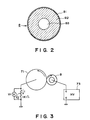
- Figure 2 is a schematic section of the cleaning roller for cleaning the intermediate transfer member employed in the laser printer of the first embodiment.
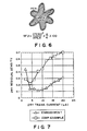
- Figure 3 is a schematic section of an instrument for measuring the resistances of the intermediate transfer member cleaning roller and the intermediate transfer member in accordance with the present invention, under an actual usage conditions.
- Figure 4 is an enlarged sectional view of the intermediate transfer member.
- Figure 5 is an explanatory drawing describing a shape factor SF1.
- Figure 6 is an explanatory drawing describing a shape factor SF2.
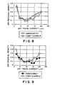
- Figure 7 is a graph showing the relationship between the secondary transfer current, and the density of the toner remaining on the intermediate transfer member after the secondary transfer, in the first embodiment.
- Figure 8 is a graph showing the relationship between the secondary transfer current, and the density of the toner remaining on the intermediate transfer member after the secondary transfer, in the second embodiment.
- Figure 9 is a graph showing the relationship between the secondary transfer current, and the density of the toner remaining on the intermediate transfer member after the secondary transfer, in the first example of third embodiment.
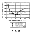
- Figure 10 is a graph showing the relationship between the secondary transfer current, and the density of the toner remaining on the intermediate transfer member after the secondary transfer, in the second example of the third embodiment.
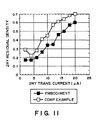
- Figure 11 is a graph showing the relationship between the secondary transfer current, and the density of the toner remaining on the intermediate transfer member after the secondary transfer, in the fourth embodiment.
- Figure 12 is an explanatory drawing depicting a mechanism through which a negative ghost related to the cleaning of the intermediate transfer member is created.
- Figure 13 is a schematic sectional view of the polymer toner in accordance with the present invention.
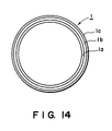
- Figure 14 is a schematic section of the structure of a photosensitive drum in accordance with the present invention.
- Figure 15 is a graph showing the primary transfer bias dependency of the primary transfer efficiency.
- Figure 16 is a graph showing the secondary transfer bias dependency of the post-secondary transfer residual toner density.
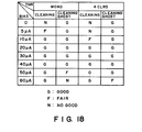
- Figure 17 is a table showing the cleaning bias dependency of the efficiency with which the surface of the intermediate transfer member is cleaned when the first photosensitive drum is employed.
- Figure 18 is a table showing the secondary transfer bias dependency of the efficiency with which the surface of the intermediate transfer member is cleaned when the second photosensitive member is employed.
- Figure 19 is a schematic sectional view of the photosensitive drum in another embodiment of the present invention.
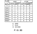
- Figure 20 is a table showing the cleaning bias dependency of the efficiency with which the surface of the intermediate transfer member is cleaned when a photosensitive drum having a surface layer with mold releasing properties is employed.
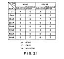
- Figure 21 is a table showing the cleaning bias dependency of the efficiency with which the surface of the intermediate transfer member is cleaned when another photosensitive drum having a surface layer with the mold releasing properties is employed.
- Figure 1 is a schematic section of the structure of a color laser beam printer, that is, a color image forming apparatus based on an electro-photographic process, in the first embodiment of the present invention.
- the printer comprises an electro-photographic photosensitive member 1 (hereinafter, "photosensitive drum") which is repeatedly used as a first image bearing member.
- This photosensitive drum 1 is rotatively driven in the counterclockwise direction indicated by an arrow mark at a predetermined peripheral speed (process speed).
- an image exposing means comprising an optical system, a scanning exposure system, or the like.
- the optical system separates the colors of an original color image, and forms optical images to which the photosensitive drum 1 is to be exposed
- the scanning exposure means comprises, for example, a laser scanner which emits a laser beam having been modulated in response to sequential electric digital image signals correspondent to the image data.
- a so-called rotary developing apparatus comprising a yellow color developing device 41, a magenta color developing device 42, a cyan color developing device 43, and a black color developing device 44, is employed.
- Each developing device is rotated in the direction indicated by an arrow mark in the drawing by an unillustrated driving apparatus, and is positioned at a developing station where it faces the photosensitive drum 1 during the developing process.
- the yellow color developing device 41 is at the developing station.
- the electrostatic latent image formed on the photosensitive drum is developed by a first developing device, that is, the yellow color developing device 41 in this embodiment, and the first color toner, that is, yellow toner Y in this embodiment, into a yellow toner image.
- a first developing device that is, the yellow color developing device 41 in this embodiment
- the first color toner that is, yellow toner Y in this embodiment
- the intermediate transfer member 5 in this embodiment is constituted of an elastic roller having a medium resistance, and is rotatively driven in the clockwise direction indicated by an arrow mark at the same peripheral speed as the photosensitive drum 1.
- a magenta (second color) toner image, a cyan (third color) toner image, a black (fourth color) toner image are sequentially transferred onto the intermediate transfer member 5 in an overlapping manner.
- a compound toner image composed of the monochromatic toner images correspondent to various color components of the target image is formed on the intermediate transfer member 5.
- a transfer belt 6 is disposed below the intermediate transfer member 5.
- the transfer belt 6 is tensioned by a bias roller 62 and a tension roller 61 which support the bias roller 6, wherein a predetermined secondary transfer bias is applied to the bias roller 62, whereas the tension roller 61 is grounded.
- the first transfer bias which transfers the negatively charged first to fourth color toner images from the photosensitive drum 1 to the intermediate transfer member 5, sequentially and in an overlapping manner, has the polarity opposite to that of the toner. In other words, it has the positive polarity in this embodiment, and is applied from a bias power source 29.
- the monochromatic color toner images having been transferred onto the surface of the intermediate transfer member 5 in the overlapping manner are transferred onto the recording medium P by placing the transfer belt 6 in contact with the intermediate transfer member 5. More specifically, the recording medium P is delivered with a predetermined timing from a sheet feeder cassette (unillustrated) to the contact nip between the intermediate transfer member 5 and the transfer belt 6, by way of a registration roller 11 and a pre-transfer guide 10, and at the same time, the secondary transfer bias is applied to the bias roller 2 from the bias power source 28.
- the monochromatic toner images having been transferred onto the intermediate transfer member 5 are transferred onto the recording medium P by the secondary transfer bias.
- this process for transferring the toner images from the intermediate transfer member 5 to the recording medium P will be called “secondary transfer process.”
- the recording medium P onto which the color toner images have been transferred all at once in the overlapping manner is introduced into a fixing device 15, being fixed therein, and then is discharged from the apparatus.
- the intermediate transfer member cleaning means which is the intermediate transfer member cleaning roller 8 in this embodiment, is placed in contact with the intermediate transfer member 5, and the toner remaining on the intermediate transfer member 5, that is, the post-secondary transfer residual toner, is charged by this intermediate transfer member cleaning roller 8 to the polarity opposite to the polarity of the toner which develops the latent image formed on the photosensitive drum, being prepared for the cleaning process in accordance with the present invention.
- the intermediate transfer member cleaning means 8 transfers the post-secondary transfer process residual toner on the intermediate transfer member 5 back to the photosensitive drum 1 at the same time as the primary transfer process from the photosensitive drum 1 to the intermediate transfer member 5. The mechanism for this cleaning process will be described next.
- the toner particles in the toner image are subjected to a strong electric field having the polarity opposite (positive polarity in this embodiment) to the normal polarity (negative polarity in this embodiment); therefore, the toner particles remaining on the intermediate transfer member 5 after the secondary transfer process, that is, the residual toner, are more likely than not to have the polarity opposite to the normal one.
- this does not means that the polarities of all the toner particles have been reversed to the positive ones. In other words, some of the toner particles in the residual toner are neutralized, bearing no charge, and some of them are partially neutralized, maintaining still the negative polarity.
- a monochromatic text pattern and a solid white text pattern were printed in succession using a laser printer structured as depicted in Figure 1.
- a ghost-like positive pattern of the preceding text pattern which resulted from the residual toner from the secondary transfer process of the preceding text pattern, appeared on the following solid white pattern print.
- the appearance of this ghost-like positive pattern was observed while varying the secondary transfer bias value relative to a predetermined value, discovering that the appearance of the resultant positive ghost image varied in response to the bias value, and the appearance of the positive ghost image was most improved (least visible) when the transfer bias was set at a value higher than the transfer bias value which gave the highest transfer efficiency.
- the inventors of the present invention made observational studies of the toner found on the intermediate transfer member 5 and the photosensitive drum 1 after the secondary transfer process.
- a charging means which was capable of not only charging the neutralized toner with no charge to the polarity opposite to that of the normal toner polarity, but also forcing the toner still maintaining the initial negative polarity, to reverse its polarity, was disposed at a point which, relative to the rotational direction of the intermediate transfer member 5, was past the secondary transfer point.
- the reason for the occurrence of the above phenomenon is that since the toner had insulating properties, the charge of the toner with the normal polarity, and the charge of the toner with the reverse polarity, did not respond to each other in a short time; neither was the toner polarity reversed nor neutralized.
- a weaker electric field is generated at the primary transfer nip between the photosensitive drum 1 and the intermediate transfer member 5 by lowering the primary transfer bias, so that the toner is prevented from being charged in the undesirable direction by the electrical discharge which occurs in the nip, two groups of toner do not exchange their charges during the short time it takes for them to pass the primary transfer nip.
- the toner on the photosensitive drum 1 and the toner on the intermediate transfer member 5 behave independently of each other.
- a contact type charging means more specifically, the intermediate transfer member cleaning roller 8 constituted of an elastic roller comprising several layers, is employed as the means for charging the toner remaining on the intermediate transfer member 5 after the secondary transfer process.
- Figure 2 is a schematic sectional view of the intermediate transfer member cleaning roller 8 actually used in this embodiment.
- the cleaning roller 8 employed in this embodiment comprises an electrically conductive, cylindrical or columnar base member 83, an elastic layer 82 placed on the base member 83, and one or more covering layers 81 covering the elastic layer 82.
- the elastic layer 83 is composed of rubber, elastomer, or the like resins.
- the material for the electrically conductive base member 83 in the cylindrical columnar form has only to be such material that is rigid enough not to allow the cleaning roller 8 to flex so that the cleaning roller 8 can be kept in contact with the intermediate transfer member 5, evenly across the entire length of the nip.
- metallic material such as aluminum, iron, or copper, alloy material such as stainless steel, or electrically conductive resin in which carbon, metallic particle, or the like is dispersed, may be employed.
- the elastic layer 82 has only to have a hardness sufficient to keep the cleaning roller 8 in contact with the intermediate transfer member 5 without leaving any gap between the two components, and a certain degree of electrically insulating properties relative to the bias to be applied.
- the following rubber material can be listed: acrylonitrile-butadiene-rubber (NBR), styrene-butadiene rubber, butadiene rubber, ethylene-propylene-rubber, chloroprene rubber, chlorosulfonated-polyethylene, chlorinated polyethylene, acrylic rubber, fluorocarbon rubber, urethane rubber, urethane sponge, and the like.
- the resistance value is desirable to be 10 5 - 10 11 ⁇ /cm, preferably, 10 5 - 10 7 ⁇ /cm (when a voltage of 1 kV is applied), in volumetric resistance.
- the overall resistance value of the intermediate transfer member cleaning roller 8 will be described later.
- the material selection for the covering layer 81 is one of the essential factors in terms of intermediate transfer member cleaning. This is because the function required of the intermediate transfer member cleaning roller 8 is the same as that of the charge roller 2 for charging the surface of the photosensitive drum 1.
- the charge roller for charging the surface of the photosensitive drum 1 may be a roller with only a single layer as long as its resistance value is extremely stable, and its surface is void of minute irregularities in resistance, so that it can satisfactorily function. This is because the charging effect is dependent on the electrical discharge which occurs between the surface material of the photosensitive drum and the surface material of the charge roller when a voltage is applied between the two materials, and the electrostatic capacity which contributes to the electrical discharge is determined by the resistance value.
- the roller in order to control the resistance, and also to suppress the effects of the minute resistance irregularities present on the surface of the roller, the roller is preferred to be structured in two layers so that two functions are separately handled, that is, the resistance value is roughly controlled by the elastic layer 82, the lower layer, and is finely controlled by the covering layer 81, the surface layer. Also, this arrangement is preferable from the standpoint of manufacturing, for example, latitude in material selection, cost, and the like.
- the two layer structure is employed in this embodiment.
- the material to be used for the covering layer 81 compound material composed of resin material such as nylon resin, urethane resin, or fluorocarbon resin, and metallic oxide such as titanium oxide or tin oxide which is dispersed in the resin material to control the resistance, is preferable.
- the covering layer may be a type of resin sheet which is wrapped over the elastic layer 82.
- the covering layer must have appropriate resistance for allowing the occurrence of electrical discharge when the roller 8 is placed in contact with the intermediate transfer member 5. More specifically, a surface resistance value within a range of 10 6 - 10 15 ⁇ /cm, more preferably, 10 11 - 10 15 ⁇ /cm 2 , (when 1 kV is applied) is effective.
- the surface resistance is measured in the following manner.
- a sample of the covering layer 8 is composed of an electrically conductive sheet with a size of 100 mm x 100 mm, and a surface layer coated thereon under similar conditions, and the resistance of this sample is measured with an R8340A and an R12704 of Advantest Corp..
- the voltage to be applied is 1 kV, wherein the discharge time and the charge time are 5 seconds and 30 seconds, respectively, and the measuring time is 30 seconds.
- the cleaning roller 8 employed in this embodiment comprises a metallic core 83 of stainless steel, an elastic member 82 of urethane sponge, and a covering layer 81.
- the external diameter of the metallic core is 14 mm.
- the thickness and volumetric resistivity of the elastic layer 82 are 3 mm and 10 5 ⁇ /cm (when 1 kV is applied), respectively.
- the covering layer 81 is composed of polyamide methoxylate in which titanium oxide is dispersed. Its thickness and surface resistance value are 10 ⁇ m and 10 13 ⁇ , respectively.
- the external diameter of the roller 8 is approximately 20 mm.
- resistance in terms of actual usage means an overall resistance of the intermediate transfer member cleaning roller 8 including the elastic layer 82, and the covering layer 81.
- an aluminum cylinder 71 is rotatively driven by an unillustrated driving force source such as a motor, and the cleaning roller 8 follows the rotation of the aluminum cylinder 71.
- the contact pressure between the two components is set up to be substantially the same as when the cleaning roller 8 is actually disposed in the apparatus illustrated in Figure 1.
- the overall contact pressure is 1 Kgf.
- a stable DC voltage Vdc is applied from a high voltage power source 73 to the metallic core of the cleaning roller 8.
- the current which flows through the elastic layer 82 and covering layer 81 of the cleaning roller 8 flows into the aluminum cylinder 71, and then, flows to the ground through a standard resistor 72.
- Vr voltage
- the obtained resistance of the cleaning roller 8 in terms of actual usage was 4 x 10 8 ⁇ .
- the preferable resistance value of the cleaning roller 8 in terms of actual usage was within a range of 5 x 10 5 - 1 x 10 10 ⁇ /cm, more preferably, 10 8 - 10 10 ⁇ /cm as measured using the aforementioned method.
- the covering layer 81 was more effective when its thickness was 5 - 100 ⁇ m.
- the intermediate transfer member 5 employed in this embodiment is also in the form of a roller. It comprises an electrically conductive, cylindrical, rigid base member 53, and at least an elastic layer 52 composed of rubber, elastomer, or the like material, and a surface layer 51 laid on the elastic layer.
- the surface layer further comprises two or more sublayers.
- electrically conductive resin material in which particles of metallic material such as aluminum, iron, or copper, particles of alloy material such as stainless steel, particles of carbon, or the like particles are dispersed, may be employed.
- structure of the cylindrical base member 53 it is in the form of the aforementioned cylinder, wherein a central shaft may penetrate through the longitudinal axis of the cylinder, or reinforcement material may fill the interior space of the cylinder.
- the metallic core employed in this embodiment is constituted of a 3 mm thick aluminum cylinder, and the reinforcement material is disposed within the internal void.
- the thickness of the elastic layer 52 of the intermediate transfer member 5 is preferred to be 0.5 - 7.0 mm in consideration of the formation of the transfer nip, the rotational color misalignment, the material cost, and the like factors.
- the surface layer 51 is preferred to be thin enough to allow the effects of the elasticity of the elastic layer 52, that is, the underlayer, to reach the surface of the photosensitive drum 1 through the surface layer 51. Preferably, it is 5 - 100 ⁇ m.
- the thicknesses of the elastic layer 52 and the surface layer 51 of the intermediate transfer member 5 are 5 mm and 10 ⁇ m, respectively, and the overall external diameter of the intermediate transfer member 5 is 180 mm.
- acrylonitrile-butadiene rubber NBR
- Ketchen black is dispersed therein to control the resistance.
- the same material as that used for the elastic layer of the aforementioned intermediate transfer member cleaning roller 8 may be listed as the rubber material usable for the elastic layer 52.
- electrically conductive material carbon black, aluminum particles, nickel particles, and the like may be employed. Further, it is conceivable to employ electrically conductive resin instead of dispersing electrically conductive agent into non-conductive resin.
- electrically conductive resin instead of dispersing electrically conductive agent into non-conductive resin.
- specific names of the usable conductive materials it is possible to list polymethyl methacrylate containing fourth-class ammonium salt, polyvinyl aniline, polyvinyl pyrrol, polydiacetylene, polyethylene imine, and the like.
- the volumetric resistivity is measured in the following manner.
- the aforementioned elastic layer 52 is cut to a size of 100 mm x 100 mm, with an optional thickness, and the volumetric resistance of this piece is measured using an R8340A and an R12704 of Advantest Corp.
- the applied voltage is 1 kV; the discharge time, 5 seconds; the charge time, 30 seconds; and the measurement time is 30 seconds.
- the surface layer 51 of the intermediate transfer member 5 is important since it greatly affects the efficiency with which the secondary transfer residual toner is cleaned.
- urethane resin is used as binder, in which aluminum boride whisker is dispersed as the conductive material for controlling resistance, and PTFE powder is dispersed to improve mold releasing properties.
- the resistance of the above surface layer is measured using the same method. It is 10 12 ⁇ /cm (when 1 kV is applied). After careful studies, the inventors of the present invention discovered that when the surface layer resistance was within a range of 10 8 - 10 12 ⁇ /cm, a preferable cleaning performance could be obtained.
- the combined resistance of the elastic layer 52 and the surface layer 51 in terms of actual usage is 10 7 ⁇ /cm (when 1 kV was applied). Also, the resistance of the intermediate transfer member 5 in terms of actual usage is measured using the same method as that used to measure the aforementioned intermediate transfer member cleaning roller 8, including the measuring system depicted in Figure 3.
- the toner employed in this embodiment is a nonmagnetic toner containing the toner particles in the irregular shapes, manufactured from styrene resin binder using a pulverizing method. It has a shape factor SF1 of 153, and a shape factor SF2 of 145, and its particle diameter is 7 ⁇ m. It is mixed with oil treated silica.
- the comparative toner it is a magnetic toner, the particles of which are in the irregular form. It is composed of a copolymer of styrene-butylacrylate-butylmaleate halfester, as a binder, and 100 parts of magnetic material such as magnetite, and is manufactured using the pulverizing method. Its shape factors SF1 and SF2 are 156 and 146, respectively. Its particle diameter is 7 ⁇ m. This toner is also mixed with oil treated silica.
- the shape factor SF1 mentioned in the foregoing is a value which indicates the roundness ratio of a spherical object. It is obtained in the following manner; the square of the maximum length MXLNG of an elliptic figure obtained by projecting a spherical object on a two dimensional flat surface is divided by the area size AREA of the elliptic figure, and the quotient is multiplied by 100 ⁇ /4.
- the shape factor SF2 is a numerical value which indicates, in ratio, configurational irregularity of an object. It is obtained in the following manner; the circumference PERI of a figure obtained by projecting an object onto a two dimensional flat surface is divided by the area size AREA of the figure, and the obtained quotient is multiplied by 100 ⁇ /4.
- SF1 and SF2 are obtained as follows. Toner images were randomly sampled using an FE-SEM (S-800), a product of Hitachi, Ltd., and the obtained data are analyzed by introducing them into an image analysis apparatus (LUSEX3), a product of NIKORE Corp., through an interface. Then, the final values were obtained from the above formulas.
- the triboelectric charges of the above mentioned two toners employed in this embodiment are approximately -15 ⁇ C/g.
- the photosensitive drum 1 employed in this embodiment is composed of OPC, and has an external diameter of 60 mm. It comprises a 0.2 - 0.3 ⁇ m thick carrier generation layer, and a 15 - 25 ⁇ m thick carrier transfer layer (hereinafter, CT layer) laminated thereon.
- the carrier generation layer is composed of phthalocyanine compound
- the CT layer is composed of polycarbonate (hereinafter, PC), that is, a binder, and a hydrazone compound dispersed therein.
- a transfer belt 6 is employed as the secondary transfer means. It does not matter whether or not a bias roller 62 and a tension roller 61, which support the transfer belt 6, are made of the same material or different material.
- NBR with a volumetric resistivity of 5 x 10 7 ⁇ cm (when 1 kV is applied) is employed. Its hardness is 30 - 35° in JIS A. Both rollers comprise a SUS core with a diameter of 8 mm, wherein the surface layer is placed so that the external diameter of each roller becomes 20 mm.
- the volumetric resistivity is within a range of 1 x 10 4 - 1 x 10 9 ⁇ /cm (when 1 kV is applied), and voltage dependency is not extremely large.
- other material such as EPDM, urethane rubber, or CR, in which appropriate conductive agent can be dispersed, may be employed.
- the transfer belt 6 is in the form of a tube, which is 80 mm in external diameter; 300 mm in length; 100 ⁇ m in wall thickness; and 10 8 - 10 15 ⁇ /cm in volumetric resistivity (when 1 kV is applied).
- a resin belt is employed as the transfer belt 6. It is made of compound material containing polycarbonate denatured by silicon, and carbon dispersed therein to control the volumetric resistivity and the surface resistance; the former is 10 11 ⁇ /cm, and the latter is 10 12 - 10 13 ⁇ .
- the resin materials there are polycarbonate (PC), nylon (PA), polyester (PET), polyethylene naphthalate (PEN), polysulfon (PSU), polyethersulfon (PEI), polyetherimide (PEI), polyethernitrile (PEN), polyether-etherketone (PEEK), thermoplastic polyimide (TPI), thermo-hardening polyimide (PI), PES alloy, polyvinylidene fluoride (PVdF), ethylene-tetrafluoroethylene copolymer (ETFE), and the like.
- thermoplastic elastomer there are polyolefin thermoplastic elastomer, polyester thermoplastic elastomer, polyurethane thermoplastic elastomer, polyurethane thermo-hardening elastomer, polystyrene thermoplastic elastomer, polyamide thermoplastic elastomer, fluorocarbon thermoplastic elastomer, polybutadiene thermoplastic elastomer, polyethylene thermoplastic elastomer, ethylene-vinyl acetate copolymer thermoplastic elastomer, polyvinyl chloride thermoplastic elastomer, and the like.
- the cleaning roller 8 As for the timing with which the cleaning roller 8 is placed in contact with the intermediate transfer member 5, when in a monochromatic continuous mode (mode for continuously producing two or more monochromatic prints), the cleaning roller 8 is placed in contact with the intermediate transfer member 5 at the same time as the primary transfer process is started. This is to prevent the image being formed from becoming disturbed by the shock generated by the contact. On the other hand, when in a four color multiple image transfer mode (mode for producing a color print bearing a color image composed of overlapping four color toner images), the cleaning roller 8 is placed in contact with the intermediate transfer member 5 at the same time as the primary transfer process for the fourth color ends.
- a monochromatic continuous mode mode for continuously producing two or more monochromatic prints
- the cleaning roller 8 is placed in contact with the intermediate transfer member 5 at the same time as the primary transfer process for the fourth color ends.
- Figure 7 is a graph showing the secondary transfer bias dependency of the density of the toner remaining on the intermediate transfer member 5 after the secondary transfer process, with reference to both the magnetic and nonmagnetic toners described above.
- the toner remaining on the intermediate transfer member 5 after the secondary transfer process is actually recovered by adhering it to a piece of adhesive tape, and then, the density of the recovered toner on the tape is measured using a Macbeth densitometer.
- the secondary transfer bias range in which the post-secondary transfer residual toner density becomes minimum is wider for the nonmagnetic toner, and in addition, its post-secondary transfer residual toner density is lower for the nonmagnetic toner.
- the amount of toner on the intermediate transfer member 5 before the secondary transfer was 0.7 mg/cm 2 .
- the amount of the residual toner on the intermediate transfer member 5 is preferred to be as small as possible.
- Figure 12 schematically depicts the above described phenomenon.
- the toner transferred onto the intermediate transfer member 5 through the primary transfer process is transferred onto the recording medium P through the secondary transfer process while maintaining the triboelectric charge of -15 ⁇ C/g.
- a majority of the toner particles remaining on the intermediate transfer member 5 after the secondary transfer process are the toner particles with positive polarity, that is, the toner particles, the polarities of which have been reversed from the normal polarity through the secondary transfer process.
- the value of the triboelectric charge of the toner on the intermediate transfer member 5 after this polarity reversal was +10 - +20 ⁇ C/g.
- the value of the triboelectric charge of the toner particles 96 having passed by the cleaning roller 8 increases to +40 - +50 ⁇ C/g.
- the residual toner is positively charged to a higher level. Consequently, the residual toner efficiently returns to the photosensitive drum 1 through the reverse transfer process.
- the amount and charge level of the toner 96 to be returned to the photosensitive drum 1 must be controlled to some degree so that cleaning failure does not occur nor does the negative ghost appear.
- the inventors of the present invention could prevent the cleaning failure and the negative ghost appearance by optimizing the transfer bias and the the value of the bias applied to the cleaning roller 8, and by using the nonmagnetic toner.
- a bias range in which both toner density lines display substantial minimum values is the optimum secondary transfer bias range adopted in this embodiment. More specifically, in the case of the nonmagnetic toner, 8 ⁇ A was used, and in the case of the magnetic toner, that is, the comparative toner, 4 ⁇ A was used.
- Table 1 shows the degree of cleaning failure and cleaning ghost appearance when the value of the bias applied to the cleaning roller is varied while using the nonmagnetic toner and the magnetic toner.
- Table 1 TONER COMP. EXAMPLE : IRREGULAR MAG.
- the cleaning failure occurred no matter which cleaning bias value was employed to charge the residual toner on the intermediate transfer member; therefore, it was impossible to clean the intermediate transfer member at the same time as the primary transfer process.
- the cleaning failure occurred when the bias value was in a range of 0 - 20 ⁇ A, and the cleaning ghost appeared when the bias value was no less than 40 ⁇ A, whereas when the cleaning bias value was 30 ⁇ A, the primary transfer process, and the reversal transfer process, that is, residual toner cleaning process, were both successfully carried out at the same time.
- the frequency at which the cleaning failure occurs or the cleaning ghost appears varies depending on the type of the developer. It is possible to think that this phenomenon is related to the amount of the residual toner 95 (mg/cm 2 ).
- the amount of the post-secondary transfer residual toner 95 was larger for the magnetic toner than for the nonmagnetic toner.
- the cleaning current was increased, it was impossible to reverse the polarity of the entire post-secondary transfer residual toner 95 to the positive polarity, and as a result, the occurrence of the cleaning failure could not be prevented.
- the intermediate transfer member cleaning means in this embodiment has the following effects:
- a roller with an external diameter of 20 mm was employed as the cleaning roller 8, but the careful studies conducted by the inventors of the present invention confirmed that any roller suffices to provide similar effects as long as its external diameter is within a range of 12 - 30 mm.
- a cylindrical photosensitive drum, and a cylindrical intermediate transfer member were employed, but obviously, a photosensitive member in the form of a belt, or an intermediate transfer member in the form of a belt can provide the same effects without any problem.
- a belt type transfer system was employed as the secondary transfer means, but employment of a corona type transfer system, or a transfer roller system, of the conventional type, does not affect the effects of the present invention.
- positively chargeable toner that is, toner chargeable to the polarity opposite to that of the toner employed in this embodiment
- toner chargeable to the polarity opposite to that of the toner employed in this embodiment is employed, provided that the polarity of the latent image is the same as that in this embodiment.
- the background exposure is used, but the relationship in electrical potential between the dark potential region and the light potential region on the photosensitive drum basically remains the same even though their polarities are reversed.
- the intermediate transfer member When the polarity of the primary transfer voltage applied to the intermediate transfer member becomes the same as that of the photosensitive drum, the intermediate transfer member cannot be cleaned; therefore, the ground potential is used.
- the toner on the photosensitive drum can be satisfactorily transferred even by the ground potential, due to the contrast in potential, and the intermediate transfer member is cleaned as the residual toner on the intermediate transfer member is reversely transferred onto the photosensitive drum due to the presence of this contrast in potential.
- the secondary transfer voltage for transferring the image onto a sheet of paper has the negative polarity, that is, the polarity opposite to that in this embodiment.
- the polarity of the intermediate transfer member cleaning bias must be rendered positive in order to charge all the secondary transfer residual toner to the positive polarity.
- a polymer toner manufactured using the suspension polymerization method was employed as the developer.
- the particles had irregular shapes, wherein the shape factor SF1 was 160 and the shape factor SF2 was 148.
- the resin portion of the polymer toner was styrene-butylacrylate. Further, when the toner was actually used, the oil treated silica was added to stabilize the triboelectric charge.
- Figure 8 shows the secondary transfer bias dependency of the post-secondary transfer residual toner density for the nonmagnetic polymer toner of this embodiment, which contained toner particles in the irregular shapes. For comparison, it also shows the same for the nonmagnetic toner containing the toner particles in the irregular shapes, which was manufactured using the pulverizing method, and was employed in the first embodiment.
- the minimum value of the post-secondary transfer residual toner density for the nonmagnetic toner is smaller than that for the nonmagnetic toner manufactured using the pulverizing method.
- the amount of the toner on the intermediate transfer member 5 before the secondary transfer was 0.7 mg/cm 2 .
- an optimum secondary transfer bias determinable from Figure 8 was used for each toner. More specifically, a bias of 8 ⁇ A was used for both the polymer toner of this embodiment in the irregular shapes, and the comparative nonmagnetic toner manufactured by the pulverizing method in the irregular shapes.
- Table 2 shows the results of another experiment in which the nonmagnetic toner in the irregular shapes, and the nonmagnetic polymer toner in the irregular shapes, were employed, and the occurrence of the cleaning failure and the appearance of the cleaning ghost were evaluated while varying the value of the bias applied to the intermediate transfer member cleaning roller 8.
- Table 2 TONER COMP. EXAMPLE : IRREGULAR NON-MAG.
- the cleaning failure occurred when the value of the cleaning bias for charging the residual toner on the intermediate transfer member was in a range of 0 - 20 ⁇ A, and the appearance of the cleaning ghost was confirmed when the cleaning bias value was no less than 40 ⁇ A, whereas when the cleaning bias value was 30 ⁇ A, the intermediate transfer member cleaning process and the primary transfer process occurred at the same time.
- the cleaning failure occurred when the cleaning bias value was within a range of 0 - 10 ⁇ A, and the cleaning ghost appeared when the cleaning bias was no less than 40 ⁇ A, indicating that when the cleaning bias value is within a range of 20 - 30 ⁇ A, the aforementioned residual toner can be successfully cleaned at the same time as the primary transfer process, and therefore, proving that the intermediate transfer member can be successfully cleaned using a relatively low cleaning bias value.
- nonmagnetic single component toner containing substantially spherical microscopic toner particles with a diameter of 7 ⁇ m was employed as the developer. It was produced using the suspension polymerization method, and contained material with a low softening point by 5 - 30 wt. %.
- the shape factors SF1 and SF2 for the toner particles were 116 and 109, respectively.
- Figure 13 schematically depicts the particle structure of the aforementioned polymer toner.
- the polymer toner particle 9 of this embodiment became spherical.
- the polymer toner particle comprised a core 93 of ester wax, a resin layer 92 of styrene-butylacrylate, and a surface layer 91 of styrene-polyester. Its specific weight was approximately 1.05. The three layer structure was given for the following reason; the presence of wax core 93 was effective to prevent offset from occurring during the fixing process, and the surface layer 91 of resin material was provided for improving charge efficiency. It should be noted here that in actual usage, oil treated silica was added to stabilize the triboelectric charge.
- Figure 9 presents a graph showing the secondary transfer bias dependency of the post-secondary transfer residual toner density for the substantially spherical nonmagnetic polymer toner employed in this embodiment. For comparison, the graph also shows the same for the nonmagnetic polymer toner containing the toner particles in the irregular shapes, which were employed in the second embodiment.
- the minimum value of the post-secondary transfer residual toner density for the nonmagnetic toner containing the substantially spherical toner particles is smaller than that for the nonmagnetic polymer toner containing the toner particles in the irregular forms.
- the amount of the toner on the intermediate transfer member 5 before the secondary transfer process was 0.7 mg/cm 2 .
- the secondary transfer bias As for the secondary transfer bias, the optimum secondary transfer bias determinable from Figure 9 was employed for each toner. More specifically, a bias value of 14 ⁇ A was used for the polymer toner containing the substantial spherical toner particles, which was employed in this embodiment, and a bias value of 8 ⁇ A was used for the polymer toner containing the toner particles in the irregular shapes, which was employed for comparison.
- Table 3 presents the results of another experiment in which the polymer toner containing the toner particles in the irregular shapes, and the polymer toner containing the toner particles in the substantially spherical shapes, and the occurrence of the cleaning failure and the appearance of the cleaning ghost, were evaluated while varying the value of the bias applied to the intermediate transfer member cleaning roller 8.
- Table 3 TONER COMP. EXAMPLE : IRREGULAR NON-MAG. POLYMERIZED TONER EMBODIMENT: SPHERICAL NON-MAG.
- the cleaning failure occurred when the cleaning bias value was within a range of 0 - 5 ⁇ A, and the cleaning ghost appeared when the cleaning bias was no less than 40 ⁇ A, indicating that when the cleaning bias value is within a range of 10 - 30 ⁇ A, the aforementioned residual toner can be successfully cleaned at the same time as the primary transfer process, and therefore, proving that the intermediate transfer member can be successfully cleaned using a relatively low cleaning bias value.
- a nonmagnetic toner was used as the developer. It was manufactured using the pulverizing method, and contained the styrene resin as the binder. It was subjected to mechanical shock, heated air flow, and high temperature liquid, to give the toner particles the substantially spherical shape. After the treatments, the shape factors SF1 and SF2 were 145 and 130, respectively, and the toner particle diameter was 7 ⁇ m.
- Figure 10 presents a graph showing the secondary transfer bias dependency of the post-secondary transfer residual toner density for the substantially spherical nonmagnetic polymer toner employed in this embodiment. For comparison, the graph also shows the same for the nonmagnetic polymer toner containing the toner particles in the irregular shapes, which were employed in the first embodiment.
- the minimum value of the post-secondary transfer residual toner density for the nonmagnetic toner containing the substantially spherical toner particles is smaller than that for the nonmagnetic polymer toner containing the toner particles in the irregular shapes.
- the amount of the toner on the intermediate transfer member 5 before the secondary transfer process was 0.7 mg/cm 2 .
- an optimum secondary transfer bias determinable from Figure 10 was employed for each toner. More specifically, a bias value of 12 ⁇ A was used for the polymer toner containing the substantially spherical toner particles, which was employed in this embodiment, and a bias value of 8 ⁇ A was used for the polymer toner containing the toner particles in the irregular shapes, which was employed for comparison.
- Table 4 presents the results of an experiment in which the nonmagnetic toner containing the toner particles in the irregular shapes, and the nonmagnetic toner containing the substantially spherical toner particles, were employed, and the occurrence of the cleaning failure and the appearance of the cleaning ghost, were observed while varying the value of the bias applied to the intermediate transfer member cleaning roller 8.
- Table 4 TONER COMP. EXAMPLE : IRREGULAR NON-MAG. TONER EMBODIMENT: SPHERICAL NON-MAG.
- the cleaning failure occurred when the value of the cleaning bias for charging the residual toner on the intermediate transfer member was in a range of 0 - 20 ⁇ A, and the appearance of the cleaning ghost was confirmed when the cleaning bias value was no less than 40 ⁇ A, whereas when the cleaning bias value was 30 ⁇ A, the intermediate transfer member cleaning process and the primary transfer process occurred at the same time.
- the cleaning failure occurred when the cleaning bias value was within a range of 0 - 10 ⁇ A, and the cleaning ghost appeared when the cleaning bias was no less than 40 ⁇ A, indicating that when the cleaning bias value is within a range of 20 - 30 ⁇ A, the aforementioned residual toner can be successfully cleaned at the same time as the primary transfer process, and therefore, proving that the intermediate transfer member can be successfully cleaned using a relatively low cleaning bias value.
- a magnetic toner containing substantially spherical toner particles with a diameter of 7 ⁇ m was used as the developer.
- This toner was manufactured by mixing 100 parts of magnetic material such as magnetite with polymer material such as styrene-butylacrylate-butylmaleate halfester copolymer, and pulverizing the compound. Further, the pulverized compound was subjected to mechanical shock, heated air flow, high temperature liquid, to give the toner particles substantially spherical shapes.
- the shape factors SF1 and SF2 of the resultant toner particle were 145 and 130, respectively. Further, oil treated silica was added as an additive.
- a magnetic toner containing toner particles in the irregular shapes was employed.
- This comparative toner was manufacture by mixing 100 parts of magnetic material such as magnetite with polymer material such as styrene-butylacrylate-butylmaleate halfester copolymer, and pulverizing the compound.
- the shape factors SF1 and SF2 of the resultant toner particle were 156 and 246, respectively, and the particle diameter was 7 ⁇ m. Further, the oil treated silica was added.
- Figure 11 presents a graph showing the secondary transfer bias dependency of the post-secondary transfer residual toner density for the substantially spherical magnetic toner employed in this embodiment. For comparison, the graph also shows the same for the magnetic toner containing the toner particles in the irregular shapes.
- the minimum value of the post-secondary transfer residual toner density for the magnetic toner containing the substantially spherical toner particles is smaller than that for the magnetic toner containing the toner particles in the irregular shapes.
- the amount of the toner on the intermediate transfer member 5 before the secondary transfer process was 0.7 mg/cm 2 .
- the secondary transfer bias an optimum secondary transfer bias determinable from Figure 11 was employed for each toner. More specifically, a bias value of 4 ⁇ A was used for both the magnetic toner containing the substantially spherical toner particles, which was employed in this embodiment, and the polymer toner containing the toner particles in the irregular shapes, which was employed for comparison.
- Table 5 presents the results of an experiment in which the magnetic toner containing the toner particles in the irregular shapes, and the magnetic toner containing the substantially spherical toner particles, were employed, and the occurrence of the cleaning failure and the appearance of the cleaning ghost, were evaluated while varying the value of the bias applied to the intermediate transfer member cleaning roller 8.
- Table 5 TONER COMP. EXAMPLE : IRREGULAR MAG. TONER EMBODIMENT: SPHERIAL MAG.
- the cleaning failure occurred no matter which value in the table was selected for the cleaning bias for charging the residual toner on the intermediate transfer member; therefore, the intermediate transfer member cleaning process concurrent with the primary transfer process, which characterizes the present invention, could not be carried out.
- the cleaning failure occurred when the cleaning bias value was within a range of 0 - 30 ⁇ A, and the cleaning ghost appeared when the cleaning bias was no less than 50 ⁇ A, indicating that when the cleaning bias value is 40 ⁇ A, the aforementioned residual toner can be successfully cleaned at the same time as the primary transfer process.
- the fourth embodiment proves that the intermediate transfer member cleaning method in accordance with the present invention is compatible even with the magnetic toner as long as the toner particle is given the substantially spherical shape.
- a mold releasing layer is provided on the surface of a photosensitive drum.
- the photosensitive drum 1 employed in this embodiment will be described.
- two types of photosensitive drum were prepared.
- a photosensitive drum for comparison (hereinafter, a first photosensitive drum) was prepared, which comprised a metallic core la of aluminum with an external diameter of approximately 60 mm, a carrier generation layer 1b, as the photosensitive layer, composed of 0.2 ⁇ m thick phthalocyanine compound laminated on the metallic core, and a carrier transfer layer lc laminated on the carrier generation layer 1b.
- the carrier generation layer was composed of polycarbonate binder, and hydrazone compound dispersed within the binder.
- a second photosensitive drum As for the photosensitive drum in accordance with the present invention (hereinafter, a second photosensitive drum), it was substantially the same as the first photosensitive drum except that Teflon particles as fluorine containing particles were dispersed in the carrier transfer layer by 10 %.
- the dispersion of the Teflon was to improve the mold releasing properties of the photosensitive drum surface.
- the amount of Teflon to be added is preferred to be no more than 20 %.
- the first photosensitive drum had a contact angle of 85°, but did not show the slipperiness at all, that is, the slipperiness could not be measured, whereas the second photosensitive drum had a contact angle of 95°, and a slipperiness of 0.8.
- the slipperiness was measured using a slipperiness tester of HEIDON, and the slipperiness of a test subject was given as a ratio relative to the slipperiness (1.0) of polyethylene terephthalate (PET); the smaller the value, the more slippery.
- the toners on the surfaces of the photosensitive drum 1 and the intermediate transfer member 5 were collected by taping, and the densities of the collected toners were measured using a Macbeth densitometer.
- the values of D1 and D2 were obtained by subtracting the density of the collection tape itself, which was 0.1 in this embodiment, from the actual measured densities.
- the second photosensitive drum provided a higher transfer efficiency using a relatively low primary transfer bias than the first photosensitive drum.
- Figure 16 shows the secondary transfer bias dependency of the density of the toner remaining on the surface of the intermediate transfer member 5 after the toner on the surface of the intermediate transfer member 5 was transferred onto the recording medium P through the secondary transfer process.
- the post-secondary transfer residual toner on the surface of the intermediate transfer member 5 was collected by taping, and the density of the collected residual toner was measured using a Macbeth densitometer; the smaller the measured density, the smaller the amount of the post-secondary transfer residual toner on the surface of the intermediate transfer member 5.
- the amount M/S of the toner on the surface of the intermediate transfer member 5 before the secondary transfer process was set at 0.5 mg/cm 2 for the monochromatic mode, and 1.4 mg/cm 2 for the four color mode.
- the amount of the residual toner on the surface of the intermediate transfer member 5 is preferred to be as small as possible.
- the secondary transfer bias was set at 12 ⁇ A.
- Figure 17 presents the results for the first photosensitive drum
- Figure 18 presents the results for the second photosensitive drum.
- cleaning failure means an undesirable condition in which a certain portion of the post-secondary transfer residual toner on the surface of the intermediate transfer member 5, which could not be attracted back to the surface of the photosensitive drum 1 in spite of the function of the cleaning roller 8, appeared, as a positive ghost, in a solid white region of the following print, that is, an undesirable condition in which the image composed of the post-secondary transfer residual toner from the first print appeared in the solid white region of the second print.
- the aforementioned proper range became wider, in particular on the upper limit side, when the second photosensitive drum was employed than when the first photosensitive drum was employed.
- the appearance of the cleaning ghost is related to the balance among the primary transfer bias which acts, at the primary transfer point, on the toner to be transferred from the surface of the photosensitive drum 1 onto the surface of the intermediate transfer member 5 through the primary transfer process, the ease with which the toner is released from the surface of the photosensitive drum 1, in other words, the mold releasing properties of the surface of the photosensitive drum 1, and the electrostatic attraction of the toner being pulled back from the surface of the intermediate transfer member 5 to the surface of the photosensitive drum 1.
- the mold releasing properties were improved by the addition of the fluorine particles to the carrier transfer layer 1c; therefore, the primary transfer bias could be lowered.
- the lowered primary bias prevented the toner polarity from being reversed through the primary transfer process.
- the condition in which the toner particles with the positive polarity of a high level are present among the toner particles remaining on the intermediate transfer member 5 after the secondary transfer was not created. Consequently, the proper range of the bias to be applied to the cleaning roller 8 became wider.
- the cleaning bias value such as the one described in the foregoing greatly contributes to the preferable cleaning of the intermediate transfer member 5, in consideration of the variation of the resistance value of the intermediate transfer member 5 or the cleaning roller 8, which occurs due to manufacturing error, the fluctuation of the resistance value of the intermediate transfer member 5 or the cleaning roller 8, which is resultant from environmental changes, and the fluctuation of the amount of the toner on the surface of the intermediate transfer member 5.
- the use of a photosensitive drum having the surface with superior mold releasing properties becomes effective.
- the intermediate transfer member could be preferably cleaned, and the cleaning roller 8, the rotation of which was slaved to the rotation of the intermediate transfer member 5, did not show any sign of wear.
- the intermediate transfer member can be cleaned at the same time as the primary transfer process is carried out; therefore, when a number of prints are continuously produced using a color laser printer, a color copying machine, or the like, the step for cleaning the surface of the intermediate transfer member 5 does not need to be inserted after each print is outputted. As a result, the throughput can be improved by a large scale.
- the polymer toner produced using the suspension polymerization method was used as the developer, but even when the toner produced using an ordinary pulverization method is used, the same effects can be obtained as long as the intermediate transfer member cleaning bias is optimized.
- the photosensitive drum 1 of this embodiment comprised a metallic core la of aluminum with an external diameter of approximately 60 mm, a 0.2 ⁇ m thick carrier generation layer 1b formed on the metallic core 1a, a 15 ⁇ m thick carrier transfer layer 1c formed on the carrier generation layer 1b, and a 3 ⁇ m thick mold releasing layer 1d formed on the carrier transfer layer 1c by dipping.
- This surface protection layer 1d was composed of a binder, which was ultraviolet hardenable acrylic, and fluorine particles (Teflon: commercial name) dispersed in the binder by 35 %. The diameters of the fluorine particles were approximately 0.3 ⁇ m.
- the photosensitive drum 1 is provided with two separate layers, that is, the carrier transfer layer and the surface layer for improving the mold releasing properties of the photosensitive drum 1, in order to separate two functions, in other words, when the carrier generation layer described in the preceding embodiment is separated into a pure carrier generation layer and a surface layer for improving the mold releasing properties of the photosensitive drum 1 (mold releasing surface layer), a larger amount of the fluorine particles can be added (to the mold releasing surface layer) than when the carrier generation has to perform two functions.
- the measured contact angle relative to water, and the measured slipperiness, of the surface of the photosensitive drum employed in this embodiment was 100° and 0.4, respectively.
- the amount of the fluorine particles to be added to the surface layer in order to improve the mold releasing properties when they are added by a too large amount, the binding force of the binder is weakened in relative terms; in other words, the strength of the surface layer is reduced, making the surface layer brittle. Therefore, the amount of the fluorine particles is preferred to be no more than 45 %.
- Figure 20 shows the results of an experiment, which was conducted using the photosensitive drum 1 described above, to prove that the efficiency with which the surface of the intermediate transfer member is cleaned is dependent on the cleaning bias applied to the cleaning roller 8.
- the intermediate transfer member 5 was reliably and preferably cleaned.
- a surface layer 1d for improving the mold releasing properties was formed as the outermost layer of the photosensitive drum 1 as in the sixth embodiment.
- it was formed using a spraying method, which characterizes this embodiment.
- the structure of the apparatus was substantially the same as that in the fifth embodiment, except that the photosensitive drum 1 was different.
- the photosensitive drum 1 of this embodiment comprised a metallic core 1a of aluminum with an external diameter of approximately 60 mm, a 0.2 ⁇ m thick carrier generation layer 1b formed on the metallic core 1a, a 15 ⁇ m thick carrier transfer layer 1c formed on the carrier generation layer 1b, and a 3 ⁇ m thick mold releasing layer 1d formed on the carrier transfer layer 1c by spraying.
- This surface protection layer 1d was composed of a binder, which was polycarbonate, and fluorine particles (Teflon: commercial name) dispersed in the binder by 35 %. The diameters of the fluorine particles were approximately 0.3 ⁇ m.
- the measured contact angle relative to water, and the measured slipperiness, of the surface of the photosensitive drum employed in this embodiment was 104° and 0.2, respectively.
- Figure 21 shows the results of an experiment, which was conducted, using the photosensitive drum 1 described above, to prove that the efficiency with which the surface of the intermediate transfer member 5 is cleaned is dependent on the cleaning bias applied to the cleaning roller 8.
- the method used for the experiment, and the conditions under which the experiment was conducted, were the same as those described in the fifth embodiment; therefore, their descriptions will be omitted.
- the intermediate transfer member 5 was reliably and preferably cleaned.
- the value of the primary transfer bias can be lowered.
- the primary transfer bias with a lower value is less likely to neutralize the triboelectric charge of the toner on the intermediate transfer member 5, improving the secondary transfer efficiency.
- the intermediate transfer member can be successfully cleaned, in practical terms, at the same time as the primary transfer process is carried out; successful reverse transfer in accordance with the present invention becomes possible.
- the developing method As for the developing method, a known noncontact developing method (jumping developing method) using a single component developer was employed.
- the toner produced using a conventional pulverization method may be employed after giving it a more spherical particle shape.
- the shape factors SF1 and SF2 of the toners employed in the aforementioned embodiments were 110 - 180, and 110 - 140, preferably, 120 - 160 and 115 - 140, respectively.
- the volumetric average diameter of the toner particle was in a range of 6 - 7 ⁇ m.
- the toner employed in the preceding embodiments was a magnetic toner containing substantially spherical toner particles, and was manufactured using the following method; 100 parts of magnetic material such as magnetite was mixed into a binder, which was styrene-butylacrylate-butylmaleate halfester; the thus obtained compound was pulverized; the pulverized compound was subjected to mechanical shock, heated air flow, and high temperature liquid, to give the compound particles spherical shapes with the shape factors SF1 and SF2 of 145 and 130, respectively. The particle diameter was 7 ⁇ m. As for the additive, oil treated silica was used.
Landscapes
- Physics & Mathematics (AREA)
- General Physics & Mathematics (AREA)
- Electrostatic Charge, Transfer And Separation In Electrography (AREA)
Applications Claiming Priority (9)
| Application Number | Priority Date | Filing Date | Title |
|---|---|---|---|
| JP12390495 | 1995-05-23 | ||
| JP12390495 | 1995-05-23 | ||
| JP123904/95 | 1995-05-23 | ||
| JP15997895 | 1995-06-02 | ||
| JP15997795 | 1995-06-02 | ||
| JP15997795 | 1995-06-02 | ||
| JP15997895 | 1995-06-02 | ||
| JP159978/95 | 1995-06-02 | ||
| JP159977/95 | 1995-06-02 |
Publications (2)
| Publication Number | Publication Date |
|---|---|
| EP0744672A1 true EP0744672A1 (de) | 1996-11-27 |
| EP0744672B1 EP0744672B1 (de) | 2003-01-02 |
Family
ID=27314825
Family Applications (1)
| Application Number | Title | Priority Date | Filing Date |
|---|---|---|---|
| EP96303593A Expired - Lifetime EP0744672B1 (de) | 1995-05-23 | 1996-05-21 | Bilderzeugungsgerät und Methode mit einem Zwischenübertragungselement |
Country Status (3)
| Country | Link |
|---|---|
| US (1) | US5809373A (de) |
| EP (1) | EP0744672B1 (de) |
| DE (1) | DE69625542T2 (de) |
Families Citing this family (22)
| Publication number | Priority date | Publication date | Assignee | Title |
|---|---|---|---|---|
| US5752130A (en) * | 1995-07-07 | 1998-05-12 | Canon Kabushiki Kaisha | Image forming apparatus for cleaning residual toner from an intermediate transfer member |
| JP3450630B2 (ja) * | 1997-02-27 | 2003-09-29 | 株式会社リコー | 画像形成装置 |
| JPH10333397A (ja) * | 1997-04-04 | 1998-12-18 | Canon Inc | カラー画像形成装置 |
| US5978639A (en) * | 1997-05-02 | 1999-11-02 | Bridgestone Corporation | Intermediate transfer member and intermediate transfer device |
| JP4208286B2 (ja) * | 1997-05-23 | 2009-01-14 | キヤノン株式会社 | 画像形成装置 |
| JPH1172979A (ja) * | 1997-07-01 | 1999-03-16 | Canon Inc | 画像形成装置 |
| JP3432727B2 (ja) | 1997-11-28 | 2003-08-04 | シャープ株式会社 | 画像形成装置 |
| JP2000010416A (ja) * | 1998-06-19 | 2000-01-14 | Canon Inc | 画像形成装置 |
| JP4250259B2 (ja) * | 1998-06-19 | 2009-04-08 | キヤノン株式会社 | 画像形成装置 |
| JP3733249B2 (ja) * | 1998-09-12 | 2006-01-11 | キヤノン株式会社 | 画像形成装置 |
| JP4027011B2 (ja) * | 1999-04-28 | 2007-12-26 | キヤノン株式会社 | 画像形成装置 |
| JP3976990B2 (ja) * | 1999-09-07 | 2007-09-19 | キヤノン株式会社 | 画像形成装置 |
| JP4004003B2 (ja) * | 1999-10-22 | 2007-11-07 | 株式会社リコー | 転写装置及び画像形成装置 |
| US6421511B2 (en) * | 1999-12-03 | 2002-07-16 | Ricoh Company, Ltd. | Transfer device and image formation apparatus |
| US6493528B2 (en) * | 2000-03-03 | 2002-12-10 | Canon Kabushiki Kaisha | Image forming unit and image forming apparatus |
| JP2003149965A (ja) | 2001-08-28 | 2003-05-21 | Canon Inc | 画像形成装置 |
| JP5006493B2 (ja) * | 2001-09-18 | 2012-08-22 | キヤノン株式会社 | 画像形成装置 |
| JP5224157B2 (ja) * | 2006-12-22 | 2013-07-03 | 株式会社リコー | 画像形成装置 |
| JP4928973B2 (ja) * | 2007-02-14 | 2012-05-09 | 株式会社リコー | クリーニング装置、プロセスカートリッジ及び画像形成装置 |
| JP5173239B2 (ja) * | 2007-04-13 | 2013-04-03 | キヤノン株式会社 | 画像形成装置 |
| JP4375441B2 (ja) * | 2007-06-04 | 2009-12-02 | コニカミノルタビジネステクノロジーズ株式会社 | 現像剤回収帯電部材、画像形成装置、およびクリーニング方法 |
| JP2009063862A (ja) * | 2007-09-07 | 2009-03-26 | Fuji Xerox Co Ltd | 帯電装置、プロセスカートリッジ、画像形成装置、およびクリーニング部材 |
Citations (5)
| Publication number | Priority date | Publication date | Assignee | Title |
|---|---|---|---|---|
| JPH01105980A (ja) * | 1987-10-19 | 1989-04-24 | Sharp Corp | 残留物転写機構を有する画像形成装置 |
| US5079597A (en) * | 1990-12-24 | 1992-01-07 | Eastman Kodak Company | Cleaning method and apparatus for intermediate transfer member |
| JPH04296785A (ja) * | 1991-03-26 | 1992-10-21 | Canon Inc | 画像形成装置 |
| JPH04340564A (ja) * | 1991-05-16 | 1992-11-26 | Matsushita Electric Ind Co Ltd | カラー画像形成装置 |
| JPH05297739A (ja) * | 1992-04-21 | 1993-11-12 | Ricoh Co Ltd | 画像形成方法 |
Family Cites Families (11)
| Publication number | Priority date | Publication date | Assignee | Title |
|---|---|---|---|---|
| JPS56153357A (en) * | 1980-04-29 | 1981-11-27 | Konishiroku Photo Ind Co Ltd | Copying device |
| JPH0629979B2 (ja) * | 1985-06-06 | 1994-04-20 | 昭和電工株式会社 | 静電荷像現像用トナ− |
| US5198863A (en) * | 1988-06-29 | 1993-03-30 | Canon Kabushiki Kaisha | Image forming apparatus |
| US5179397A (en) * | 1989-04-03 | 1993-01-12 | Canon Kabushiki Kaisha | Image forming apparatus with constant voltage and constant current control |
| US5264902A (en) * | 1990-02-07 | 1993-11-23 | Canon Kabushiki Kaisha | Image forming device |
| US5173735A (en) * | 1990-06-07 | 1992-12-22 | Minolta Camera Kabushiki Kaisha | Image forming apparatus with improved cleaning operation |
| JP2840483B2 (ja) * | 1991-06-28 | 1998-12-24 | キヤノン株式会社 | 画像形成装置 |
| JPH05297738A (ja) * | 1992-04-20 | 1993-11-12 | Fuji Xerox Co Ltd | カラー画像形成装置 |
| JP3057121B2 (ja) * | 1992-04-28 | 2000-06-26 | 株式会社リコー | 画像形成装置 |
| JP3253205B2 (ja) * | 1993-01-06 | 2002-02-04 | キヤノン株式会社 | 電子写真感光体、該電子写真感光体を有する電子写真装置および装置ユニット |
| US5732310A (en) * | 1995-04-21 | 1998-03-24 | Canon Kabushiki Kaisha | Image forming apparatus having cleaning device for cleaning intermediate transfer member |
-
1996
- 1996-05-21 US US08/651,858 patent/US5809373A/en not_active Expired - Lifetime
- 1996-05-21 EP EP96303593A patent/EP0744672B1/de not_active Expired - Lifetime
- 1996-05-21 DE DE69625542T patent/DE69625542T2/de not_active Expired - Lifetime
Patent Citations (5)
| Publication number | Priority date | Publication date | Assignee | Title |
|---|---|---|---|---|
| JPH01105980A (ja) * | 1987-10-19 | 1989-04-24 | Sharp Corp | 残留物転写機構を有する画像形成装置 |
| US5079597A (en) * | 1990-12-24 | 1992-01-07 | Eastman Kodak Company | Cleaning method and apparatus for intermediate transfer member |
| JPH04296785A (ja) * | 1991-03-26 | 1992-10-21 | Canon Inc | 画像形成装置 |
| JPH04340564A (ja) * | 1991-05-16 | 1992-11-26 | Matsushita Electric Ind Co Ltd | カラー画像形成装置 |
| JPH05297739A (ja) * | 1992-04-21 | 1993-11-12 | Ricoh Co Ltd | 画像形成方法 |
Non-Patent Citations (4)
| Title |
|---|
| PATENT ABSTRACTS OF JAPAN vol. 013, no. 347 (P - 910) 4 August 1989 (1989-08-04) * |
| PATENT ABSTRACTS OF JAPAN vol. 017, no. 107 (P - 1496) 4 March 1993 (1993-03-04) * |
| PATENT ABSTRACTS OF JAPAN vol. 017, no. 189 (P - 1521) 13 April 1993 (1993-04-13) * |
| PATENT ABSTRACTS OF JAPAN vol. 018, no. 096 (P - 1694) 16 February 1994 (1994-02-16) * |
Also Published As
| Publication number | Publication date |
|---|---|
| DE69625542T2 (de) | 2003-10-02 |
| US5809373A (en) | 1998-09-15 |
| EP0744672B1 (de) | 2003-01-02 |
| DE69625542D1 (de) | 2003-02-06 |
Similar Documents
| Publication | Publication Date | Title |
|---|---|---|
| US5809373A (en) | Image forming apparatus which back-transfers residual toner from an intermediate transfer member to a photosensitive drum | |
| EP0738938B1 (de) | Bilderzeugungsgerät und Verfahren mit Zwischenübertragungselement | |
| EP0760495B1 (de) | Bilderzeugungsgerät | |
| EP1329778A1 (de) | Bilderzeugungsgerät und abnehmbare Zwischenbildträger-Einheit | |
| JP3267507B2 (ja) | 画像形成装置 | |
| EP0840175B1 (de) | Ein Bilderzeugungsgerät | |
| JP3287739B2 (ja) | 画像形成装置 | |
| US6560427B2 (en) | Electrophotographic image forming apparatus | |
| JP4114991B2 (ja) | 画像形成装置 | |
| JP2007078750A (ja) | 画像形成装置 | |
| JP3342288B2 (ja) | 画像形成装置 | |
| JP3021363B2 (ja) | 画像形成装置 | |
| JP2000242152A (ja) | カラー画像形成装置 | |
| JP3359231B2 (ja) | 画像形成装置 | |
| JPH09244430A (ja) | 画像形成装置 | |
| JP2001272833A (ja) | 画像形成装置 | |
| JP3308741B2 (ja) | 画像形成装置 | |
| JP3082546B2 (ja) | 画像形成装置 | |
| JPH1049019A (ja) | 画像形成装置 | |
| JP3513355B2 (ja) | 画像形成装置 | |
| HK1012072B (en) | Image forming apparatus and method using intermediate transfer member | |
| JPH09325575A (ja) | 画像形成装置 | |
| JP3257658B2 (ja) | 画像形成装置 | |
| JPH09304998A (ja) | 画像形成装置 | |
| JP2004191566A (ja) | 画像形成装置 |
Legal Events
| Date | Code | Title | Description |
|---|---|---|---|
| PUAI | Public reference made under article 153(3) epc to a published international application that has entered the european phase |
Free format text: ORIGINAL CODE: 0009012 |
|
| AK | Designated contracting states |
Kind code of ref document: A1 Designated state(s): DE FR GB IT |
|
| 17P | Request for examination filed |
Effective date: 19970409 |
|
| 17Q | First examination report despatched |
Effective date: 19990617 |
|
| RTI1 | Title (correction) |
Free format text: IMAGE FORMING APPARATUS AND METHOD EMPLOYING AN INTERMEDIATE TRANSFER MEMBER |
|
| RTI1 | Title (correction) |
Free format text: IMAGE FORMING APPARATUS AND METHOD EMPLOYING AN INTERMEDIATE TRANSFER MEMBER |
|
| GRAG | Despatch of communication of intention to grant |
Free format text: ORIGINAL CODE: EPIDOS AGRA |
|
| GRAH | Despatch of communication of intention to grant a patent |
Free format text: ORIGINAL CODE: EPIDOS IGRA |
|
| GRAH | Despatch of communication of intention to grant a patent |
Free format text: ORIGINAL CODE: EPIDOS IGRA |
|
| GRAA | (expected) grant |
Free format text: ORIGINAL CODE: 0009210 |
|
| AK | Designated contracting states |
Kind code of ref document: B1 Designated state(s): DE FR GB IT |
|
| REG | Reference to a national code |
Ref country code: GB Ref legal event code: FG4D Free format text: 20030102 |
|
| REF | Corresponds to: |
Ref document number: 69625542 Country of ref document: DE Date of ref document: 20030206 Kind code of ref document: P |
|
| ET | Fr: translation filed | ||
| PLBE | No opposition filed within time limit |
Free format text: ORIGINAL CODE: 0009261 |
|
| STAA | Information on the status of an ep patent application or granted ep patent |
Free format text: STATUS: NO OPPOSITION FILED WITHIN TIME LIMIT |
|
| 26N | No opposition filed |
Effective date: 20031003 |
|
| PGFP | Annual fee paid to national office [announced via postgrant information from national office to epo] |
Ref country code: GB Payment date: 20140523 Year of fee payment: 19 |
|
| PGFP | Annual fee paid to national office [announced via postgrant information from national office to epo] |
Ref country code: DE Payment date: 20140531 Year of fee payment: 19 Ref country code: IT Payment date: 20140507 Year of fee payment: 19 |
|
| PGFP | Annual fee paid to national office [announced via postgrant information from national office to epo] |
Ref country code: FR Payment date: 20140528 Year of fee payment: 19 |
|
| REG | Reference to a national code |
Ref country code: DE Ref legal event code: R119 Ref document number: 69625542 Country of ref document: DE |
|
| GBPC | Gb: european patent ceased through non-payment of renewal fee |
Effective date: 20150521 |
|
| PG25 | Lapsed in a contracting state [announced via postgrant information from national office to epo] |
Ref country code: IT Free format text: LAPSE BECAUSE OF NON-PAYMENT OF DUE FEES Effective date: 20150521 |
|
| REG | Reference to a national code |
Ref country code: FR Ref legal event code: ST Effective date: 20160129 |
|
| PG25 | Lapsed in a contracting state [announced via postgrant information from national office to epo] |
Ref country code: GB Free format text: LAPSE BECAUSE OF NON-PAYMENT OF DUE FEES Effective date: 20150521 Ref country code: DE Free format text: LAPSE BECAUSE OF NON-PAYMENT OF DUE FEES Effective date: 20151201 |
|
| PG25 | Lapsed in a contracting state [announced via postgrant information from national office to epo] |
Ref country code: FR Free format text: LAPSE BECAUSE OF NON-PAYMENT OF DUE FEES Effective date: 20150601 |