EP0741015B1 - Vorrichtung zum umfänglichen und seitlichen Verstellen des Plattenzylinders - Google Patents
Vorrichtung zum umfänglichen und seitlichen Verstellen des Plattenzylinders Download PDFInfo
- Publication number
- EP0741015B1 EP0741015B1 EP96104952A EP96104952A EP0741015B1 EP 0741015 B1 EP0741015 B1 EP 0741015B1 EP 96104952 A EP96104952 A EP 96104952A EP 96104952 A EP96104952 A EP 96104952A EP 0741015 B1 EP0741015 B1 EP 0741015B1
- Authority
- EP
- European Patent Office
- Prior art keywords
- shaft
- cylinder
- bush
- threaded
- gear wheel
- Prior art date
- Legal status (The legal status is an assumption and is not a legal conclusion. Google has not performed a legal analysis and makes no representation as to the accuracy of the status listed.)
- Expired - Lifetime
Links
- 230000005540 biological transmission Effects 0.000 description 3
- 238000004519 manufacturing process Methods 0.000 description 1
- 239000000463 material Substances 0.000 description 1
- 238000005096 rolling process Methods 0.000 description 1
Images


Classifications
-
- B—PERFORMING OPERATIONS; TRANSPORTING
- B41—PRINTING; LINING MACHINES; TYPEWRITERS; STAMPS
- B41F—PRINTING MACHINES OR PRESSES
- B41F13/00—Common details of rotary presses or machines
- B41F13/08—Cylinders
- B41F13/10—Forme cylinders
- B41F13/12—Registering devices
- B41F13/14—Registering devices with means for displacing the cylinders
-
- Y—GENERAL TAGGING OF NEW TECHNOLOGICAL DEVELOPMENTS; GENERAL TAGGING OF CROSS-SECTIONAL TECHNOLOGIES SPANNING OVER SEVERAL SECTIONS OF THE IPC; TECHNICAL SUBJECTS COVERED BY FORMER USPC CROSS-REFERENCE ART COLLECTIONS [XRACs] AND DIGESTS
- Y10—TECHNICAL SUBJECTS COVERED BY FORMER USPC
- Y10T—TECHNICAL SUBJECTS COVERED BY FORMER US CLASSIFICATION
- Y10T74/00—Machine element or mechanism
- Y10T74/19—Gearing
- Y10T74/1956—Adjustable
Definitions
- the present invention relates to a device for adjusting the circumference and Page register in a rotary printing press.
- a plate cylinder In a rotary offset machine, a plate cylinder is in rolling contact with one Rubber cylinder, which in turn contacts the web (the material to be printed). in the The course of a print run must often change the position of the Plate cylinder to be adjusted to the rubber cylinder.
- An adjustment can For example, it may be necessary to have the printed image with one already on the web located image is in register.
- the register can be adjusted laterally (in the direction of the Cylinder axes) or circumferentially (in the direction of rotation).
- a corresponding Adjustment can take place, for example, in a typical color printing machine with four Printing units, each printing unit printing dots in a special color, required become. The combination of these colored dots on paper gives a colored picture. Each set of colored dots must be printed aligned with the others so that a sharp colored image is obtained. If the dots are printed with misalignment, the register of the printing units must be adjusted so that the printing units get their points in print correct fit.
- EP 0 262 298 A2 describes a register setting device for adjusting the Page and circumference registers in a rotary printing press, on which one with one Plate cylinder journal rotatably connected fine-thread shaft an internal thread sleeve is arranged, which is rotatable with an axially arranged on the cylinder journal slidable drive gear for the cylinder is connected.
- the fine-thread shaft is located in the side register in an internal threaded bushing fixed to the frame a first drive rotates and shifts the cylinder journal in the axial direction.
- the shortcomings of the known devices thereby eliminated that lateral and circumferential adjuster with a simple design on the same side of the machine are provided.
- the design is simple because of one Precision threaded shaft is used in two different operating modes: one for the Side register and once for the circumferential register.
- a socket with an internal thread is provided.
- a Precision threaded shaft is arranged in the threaded bush and engages with it.
- the shaft is connected to the plate cylinder so that the plate cylinder at the side Movement the shaft is moved sideways.
- the shaft is powered by a first drive turned.
- the threaded bush is turned by a second drive.
- the threaded bush is connected to the plate cylinder by a gear so that the Plate cylinder rotates when the threaded bushing moves laterally.
- the gearbox also includes a bevel, on which a groove is formed on the inside engages with the wedge.
- the helix can be rotated with the threaded bush connected.
- the incline is on the outside of the rubber cylinder attached gear engaged. A lateral force is exerted on the bevel by the lateral movement of the threaded bushing is exerted so that when the threaded bushing turns moved sideways, the degree of inclination is moved sideways and rotates (by combing with the rubber cylinder gear) so that a circumferential movement of the plate cylinder is effected with respect to the rubber cylinder.
- the shaft In order to adjust the side register, the shaft is replaced by the first Drive rotated while holding the bushing. Because of their threaded connection with the threaded bush, the rotating shaft moves laterally and moves the Plate cylinder on the side.
- the threaded bush is replaced by the second one Drive rotated while holding the shaft. Due to their threaded connection with the shaft moves the threaded bushing sideways, thereby driving the gear and causes the plate cylinder to be rotated circumferentially as described above.
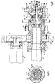
- Fig. 1 shows a known device in which the devices for adjusting the Perimeter register and page register on the same side of the press are provided, but two precision threaded shafts 90, 100 are required.
- the device is a plate cylinder 1 with a user-side bearing journal 2 and one drive-side bearing journal (not shown) connected.
- the trunnions are through bearing 4 rotatably supported in the respective side frame 3.
- a first precision threaded shaft 90 is hollow within a second Precision threaded shaft 100 arranged.
- the first wave 90 is also within one Threaded sliding plate 230 and is in threaded engagement therewith.
- the first wave 90 is on one end stored in bearings 110.
- the bearings 110 are on a bevel 150 with a Ring 120 and screws 140 attached so that the first shaft 90 is independent of the Bevel 150 can turn. Lateral movement of shaft 90 regardless of that Bevel 150 is not possible.
- a gear 130 is on the first shaft 90 attached. Gear 130 is connected to a first motor (not shown).
- the second precision threaded shaft 100 is arranged within a play nut 220 and is in threaded engagement with this.
- the second shaft 100 is supported with bearings 170.
- the Bearings 170 are with the plate cylinder journal 2 by screws 180, 190 and a gear 200, which is attached to the end of the journal 2, so that the second shaft 100th can rotate independently of the journal 2.
- shaft 100 independent of the journal 2 is not possible.
- a gear 160 is on attached to the second shaft 100.
- the gear 160 is with a second motor (not shown) in connection.
- the known device In a first operating mode, the known device according to FIG. 1 provides the extensive Register the plate cylinder 1 by turning the first threaded shaft 90. If the first Rotated shaft by its gear 130, the first shaft 90 moves laterally, conditionally through the threaded connection with the plate 230. The lateral movement of the first shaft 90 is transferred to the bevel 150 by bearing 110, ring 120 and screws 140. The Bevel 150 engages another bevel (not shown) that is at the end a rubber cylinder (not shown) of the press is attached. When moving the Bevel 150, the relative circumferential positions of the plate cylinder 1 and Gummiyzlinders (not shown) changed, whereby extensive register accuracy is achieved becomes.
- the conventional device according to FIG. 1 provides the lateral one Register the plate cylinder 1 by rotating the second shaft 100.
- the second shaft 100 rotated by its gear 160, the second shaft 100 moves laterally, conditionally through their threaded connection with the plate 220.
- This lateral movement is due to the Plate cylinder 1 via the bearings 170, screws 180, 190, gear 200 and bearing journal 2 transferred, whereby a lateral register accuracy is achieved.
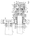
- FIGS. 2-4 show a device for adjusting the lateral and circumferential fit of a cylinder according to an embodiment of the present Invention.
- a single shaft causes both lateral as well as extensive register adjustment.
- 2 shows a plate cylinder 1, that with an operator-side bearing journal 2 and a drive-side bearing journal (not shown) is connected.
- the journals are through bearing 4 in their respective side frames 3 rotatably mounted.
- a rubber cylinder 5 is equally with an operator side Bearing pin 6 and a drive-side bearing pin (not shown) connected.
- This Bearing journals are equally rotatable by bearings 7 in their respective side frames 3 stored.
- a helical gear or helical gear 8 is at the end of the operator-side bearing pin 6 of the rubber cylinder attached.
- a single precision threaded shaft 9 is arranged within a bush 10 and stands with the socket 10 in threaded connection.
- the shaft 9 is at one end through bearing 11 stored.
- the bearings 11 are coaxial at the end of the adjustable journal 2 of the Plate cylinder fixed by a ring 12 and screws 13 so that the shaft 9th can rotate independently of the plate cylinder 1. Lateral movement of shaft 9 independent of the plate cylinder 1 is not possible.
- the shaft 9 is also arranged within mother plates 14, 15 and is in threaded connection therewith.
- the mother plates 14, 15 are fastened to one another, and those consisting of 14 and 15
- the assembly is fitted in an opening in a register drive plate 17.
- a Threaded collar or collar 16 is a mechanical stop in the lateral direction intended.
- gear 18 is connected to a first motor (not shown). In the embodiment of the present invention shown in FIG. 2, the first form Motor and the gear 18 the shaft drive of the shaft 9.
- the bushing 10 is arranged within a gearwheel 21 and fastened to it.
- the Gear 21 is externally engaged with a pinion 22.
- the pinion 22 is coaxial with one Shaft 23 attached.
- the pinion 22 is so long in the lateral direction that it with the Gear 21 remains engaged over the entire side adjustment path of the gear 21.
- the Shaft 23 passes through the register drive plate 17.
- a bevel gear 24 is on coaxially plate 17 attached to the end of the shaft 23 outside the register drive plate.
- the bevel gear 24 stands with a second motor (not shown) in connection.
- the second motor, the bevel gear 24, the Shaft 23, the pinion 22 and the gear 21 together form the bush drive of the bush 10 in the embodiment of the present invention shown in FIG. 2.
- the bush 10 is through bearing 25, the circumferential, free rotation of the bush 10 allow stored. However, the socket 10 is fitted in its bearing 25 so that lateral The bushing 10 cannot slip in the bearings 25.
- the bearings 25 are in one Collar or ring unit 26 arranged to facilitate manufacture from a Inner ring and an outer ring 28 there.
- the outer ring 28 is on with screws 29 attached to the inner ring.
- the inner ring has an integral lip 30 which lies such that the bearing 25 can press against the lip 30.
- the outer ring 28 has one integral lip 31, which lies so that the bearing 25 can press against the lip 31.
- the ring 26 is fastened to a bevel 32 with four screws 33.
- the slant 32 is externally engaged with the bevel 8 of the blanket cylinder.
- a straight wedge 34 is provided in the bevel degree 32 and is in engagement therewith.
- the straight wedge 34 is like this arranged and mounted on the adjustable journal 2 of the plate cylinder that circumferential rotation of the wedge 34 is not possible regardless of the plate cylinder 1.
- the straight wedge 34 limits the freedom of movement of the bevel 32 and prevents it rotating the bevel 32 circumferentially with respect to the platter cylinder 1.
- a spur gear 35 is for driving the application roller (not shown) of the printing press intended.
- the spur gear 35 is driven by the connection with the operator bearing journal.
- the side register is turned by rotating the shaft 9 set.
- the socket 10 is held by the socket drive.
- the shaft drive drives the gear 18, and this in turn rotates the shaft 9 either in Clockwise or counterclockwise. Since the shaft 9 with the mother plates 14, 15 and the socket 10 is in threaded connection, the shaft 9 is driven laterally, namely in a direction corresponding to the direction of rotation.
- the shaft 9 pushes or pulls the Plate cylinder 1 in the lateral direction by power transmission via the shaft bearing 11 in this way the plate cylinder 1 is adjusted laterally.
- the extensive register is turned by turning the socket 10 set.
- the shaft 9 is held by the shaft drive.
- the bevel gear 24 drives the bevel gear 24, which in turn rotates the bush, either in Clockwise or counterclockwise. Since the socket 10 is in threaded connection with the held shaft 9, the socket 10 is driven laterally in one of the directions of rotation corresponding direction.
- the bushing 10 transmits lateral forces via its bearings 25, then via the ring unit 26 and continue on the screws 33 to the bevel 32.
- the bevel 32 is in this way moved laterally in a direction corresponding to the direction of rotation of the bushing 10. Since that Bevel 32 with the bevel 8 of the blanket cylinder engages, the bevel 32 forced to circumferential rotation with respect to the rubber cylinder 5.
- the Circumferential movement of the bevel 32 with respect to the blanket cylinder 8 transmits Circumferential forces over the straight wedge 34, causing circumferential rotation of the plate cylinder 1 is effected with respect to the blanket cylinder 5. In this way, a register is maintained achieved in the circumferential direction.
- the plate cylinder 1 and the Rubber cylinder 5 rotated, for example, by a gear train 300, the one Main drive gear 310 is connected.
- the transmission 310 is replaced by a DC motor driven by a belt (not shown).
- the journal 2 of the Plate cylinder, the bevel 32, the straight wedge 34, the spur gear 35, the screws 33 and the rings 12, 26 rotate together with the plate cylinder 1.
- the bevel 8 and the Bearing journals 6 of the rubber cylinder rotate together with this.
- the wave 9 and the Bushing 10 with storage, as through its bearings 11, 25, do not rotate together with the Plate cylinder 1.
- Fig. 5 shows another embodiment of the present invention, in which the Helical gears 8, 32 of the embodiment of FIG. 2 are replaced by spur gears 88, 82 and the straight wedge 34 of the embodiment of FIG. 2 is replaced by a screw wedge 84.
- the gear 18 of the shaft drive is replaced by a gear 36.
- Components; which correspond to one another in the embodiments of FIGS. 2 and 5 have the same Reference numerals.
- the shaft 9 rotates when the side register is set prevented from the register drive plate 17 by a pin 39 which in the shaft 9th is pressed and sits in a groove in the plate 17.
- a holder 37 in the Register drive plate 17 fastened with a screw 38 and prevents axial Movement of the gear 36.
- the gear 36 is rotated the first motor while the bush drive (gears 24, 21, shaft 23, pinion 22 and second motor) is held.
- the gear 36 rotates, it moves the shaft 9 axially, but not circumferentially due to the threaded connection between the shaft 9 and the Gear 36.
Landscapes
- Engineering & Computer Science (AREA)
- Mechanical Engineering (AREA)
- Rotary Presses (AREA)
- Inking, Control Or Cleaning Of Printing Machines (AREA)
Description
- Fig. 1
- einen Querschnitt der Bedienerseite einer Rotationsdruckmaschine, einschließlich einer seitlichen/umfänglichen Registerverstellvorrichtung des Standes der Technik;
- Fig. 2
- einen Querschnitt der Bedienerseite einer Rotationsdruckmaschine, einschließlich einer Vorrichtung gemäß einer Ausführungsform der vorliegenden Erfindung;
- Fig. 3
- eine Längsansicht der Vorrichtung nach Fig. 2 entlang der Linie A-A;
- Fig. 4
- eine Ansicht der Antriebsseite der Ausführungsform nach Fig. 2;
- Fig. 5
- einen Querschnitt einer alternativen Ausführungsform der vorliegenden Erfindung.
- 1
- Plattenzylinder
- 2
- Verstellseitiger Lagerzapfen
- 3
- Seitenrahmen
- 4
- Lager
- 5
- Gummizylinder
- 6
- Verstellseitiger Lagerzapfen
- 7
- Lager
- 8
- Schrägrad
- 9
- Präzisionsgewindewelle
- 10
- Buchse
- 11
- Lager
- 12
- Ring
- 13
- Schraube
- 14
- Mutterplatte
- 15
- Mutterplatte
- 16
- Gewindespannring
- 17
- Registerantriebsplatte
- 18
- Zahnrad
- 19
- Scheibe
- 20
- Schraube
- 21
- Zahnrad
- 22
- Ritzel
- 23
- Welle
- 24
- Kegelrad
- 25
- Lager
- 26
- Ringgruppe
- 28
- Außerring
- 29
- Schraube
- 30
- Lippe
- 31
- Lippe
- 32
- Schrägrad
- 33
- Schraube
- 34
- Gerader Keil
- 35
- Stirnrad
- 36
- Zahnrad
- 37
- Halter
- 38
- Schraube
- 39
- Stift
- 82
- Stirnrad
- 84
- Schraubenkeil
- 88
- Stirnrad
- 90
- Präzisisionsgewindewelle, erste
- 100
- Präzisionsgewindewelle, zweite
- 110
- Lager
- 120
- Ring
- 130
- Zahnrad
- 140
- Schraube
- 150
- Schrägrad
- 160
- Zahnrad
- 170
- Lager
- 180
- Schraube
- 190
- Schraube
- 200
- Zahnrad
- 210
- Schraube
- 220
- Spielmutter
- 230
- Platte
- 300
- Getriebezug
- 310
- Hauptantriebsgetriebe
Claims (7)
- Vorrichtung zum seitlichen und umfänglichen Verstellen eines Zylinders (1) einer Rotationsdruckmaschinemit einer Buchse (10) mit einer Innenfläche mit Gewinde;einer Welle (9) innerhalb der Buchse (10), die mit dem Zylinder (1) verbunden ist, so daß der Zylinder (1) bei seitlicher Bewegung der Welle (9) seitlich bewegt wird, wobei die Welle (9) eine Außenfläche mit einem Gewinde besitzt, das in das Gewinde an der Innenfläche der Buchse (10) eingreift;einem an die Buchse (10) gekoppelten Getriebe (8, 32) derart, daß eine Drehbewegung der Buchse (10) eine umfängliche Bewegung des Zylinders (1) bewirkt;einem ersten Antrieb (18) zum Drehen der Welle (9) in der Weise, daß beim Drehen der Welle (9) die Welle (9) seitlich bewegt wird, wobei die seitliche Bewegung der Welle (9) den Zylinder (1) seitlich bewegt;sowie mit einem zweiten Antrieb (22, 24, 23) zum Drehen der Buchse (10) in der Weise, daß beim Drehen der Buchse (10) die Buchse (10) das Getriebe treibt, wobei das Getriebe den Zylinder (1) umfänglich dreht,
dadurch gekennzeichnet,daß das Getriebe eine Keilbuchse umfaßt, die an dem verstellseitigen Lagerzaphen (2) des Zylinders (1) montiert und koaxial zu diesem angeordnet ist, und eine Außenfläche mit einem Keil (34, 84) aufweist, wobei ein umfängsliches Drehen als teils (34) unabhängig vom Zylinder nicht möglich ist;und daß ein mit der Buchse (10) drehbar verbundenes Zahnrad (32, 82) vorgesehen ist, welches eine Innenfläche mit einer darauf angeordneten Nut besitzt, die den Keil (34, 84) aufnimmt. - Vorrichtung zum seitlichen und umfänglichen Verstellen eines Zylinders (1) einer Rotationsdruckmaschine miteiner Welle (9), die koaxial mit dem Zylinder (1) angeordnet ist, wobei die Welle (9) mit dem Zylinder (1) drehbar verbunden ist und die Welle eine Außenfläche mit einem Gewinde aufweist;einer Gewindebuchse (10), die koaxial mit dem Zylinder (1) verbunden ist, wobei die Buchse (10) eine Innenfläche mit Gewinde besitzt und das Gewinde mit dem Gewinde an der Außenfläche der Welle (9) in Verbindung steht;einer Keilbuchse, die an dem verstellseitigen Lagerzaphen (2) des Zylinder (1) und koaxial zu diesem angeordnet ist, und die eine Außenfläche mit einem Keil (34, 84) aufweist; wobei ein umfängliches Drehen als teils (34) unabhängig vom Zylinder (1) nicht möglicht ist;einem Zahnrad (32, 82) mit einer Innenfläche und einer auf dieser angeordneten Nut, die mit dem Keil (34, 84) in Eingriff steht, wobei das Zahnrad mit der Gewindebuchse (10) drehbar verbunden ist;einem ersten Antrieb zum axialen Bewegen der Welle (9) ohne diese zu drehen, in der Weise, daß die Welle (9) den Zylinder (1) seitlich bewegt;einem zweiten Antrieb zum Drehen der Gewindebuchse (10) in der Weise, daß beim Drehen der Gewindebuchse (10) die Gewindebuchse (10) das Zahnrad (32, 82) seitlich bewegt, das Zahnrad (32, 82) die Keilbuchse antreibt und dadurch den Zylinder (1) dreht.
- Vorrichtung gemäß Anspruch 1 oder 2,
dadurch gekennzeichnet,daß das Zahnrad ein Schrägrad (32) und der Keil ein gerader Keil (34) ist. - Vorrichtung gemäß Anspruch 1 oder 2,
dadurch gekennzeichnet,daß das Zahnrad ein Stirnrad (82) und der Keil ein Schraubenkeil (84) ist. - Vorrichtung gemäß Anspruch 3,
dadurch gekennzeichnet,daß das Zahnrad (32, 82) koaxial mit dem Zylinder (1) angeordnet und am gleichen Ende des Zylinders (1) wie die Gewindebuchse (10) vorgesehen ist. - Vorrichtung gemäß Anspruch 2,
dadurch gekennzeichnet,daß der erste Antrieb zum axialen Bewegen der Welle (9) einen Stift (39) aufweist, der die Welle (9) an einer Rotation hindert. - Vorrichtung nach einem der Ansprüche 2 bis 6,
dadurch gekennzeichnet,daß der erste Antrieb ein Zahnrad (36) aufweist, das über eine Gewindeverbindung mit der Welle (9) verbunden ist und über einen mit einer Registerantriebsplatte (17) verbundenen Halter (37) axial unbeweglich gehalten wird, in der Weise, daß bei einer Drehung des Zahnrades (36) die Welle (9) in axialer Richtung bewegt wird.
Applications Claiming Priority (2)
| Application Number | Priority Date | Filing Date | Title |
|---|---|---|---|
| US08/435,932 US5535675A (en) | 1995-05-05 | 1995-05-05 | Apparatus for circumferential and lateral adjustment of plate cylinder |
| US435932 | 1995-05-05 |
Publications (3)
| Publication Number | Publication Date |
|---|---|
| EP0741015A2 EP0741015A2 (de) | 1996-11-06 |
| EP0741015A3 EP0741015A3 (de) | 1997-10-01 |
| EP0741015B1 true EP0741015B1 (de) | 1999-08-18 |
Family
ID=23730418
Family Applications (1)
| Application Number | Title | Priority Date | Filing Date |
|---|---|---|---|
| EP96104952A Expired - Lifetime EP0741015B1 (de) | 1995-05-05 | 1996-03-28 | Vorrichtung zum umfänglichen und seitlichen Verstellen des Plattenzylinders |
Country Status (5)
| Country | Link |
|---|---|
| US (2) | US5535675A (de) |
| EP (1) | EP0741015B1 (de) |
| JP (1) | JPH08300606A (de) |
| CA (1) | CA2175844C (de) |
| DE (1) | DE59602767D1 (de) |
Cited By (5)
| Publication number | Priority date | Publication date | Assignee | Title |
|---|---|---|---|---|
| US7516698B2 (en) | 2005-03-30 | 2009-04-14 | Goss International Americasn, Inc. | Web offset printing press with autoplating |
| US7775159B2 (en) | 2005-03-30 | 2010-08-17 | Goss International Americas, Inc. | Cantilevered blanket cylinder lifting mechanism |
| US7819057B2 (en) | 2005-03-30 | 2010-10-26 | Goss International Americas, Inc. | Print unit having blanket cylinder throw-off bearer surfaces |
| US7849796B2 (en) | 2005-03-30 | 2010-12-14 | Goss International Americas, Inc | Web offset printing press with articulated tucker |
| US8037818B2 (en) | 2005-04-11 | 2011-10-18 | Goss International Americas, Inc. | Print unit with single motor drive permitting autoplating |
Families Citing this family (21)
| Publication number | Priority date | Publication date | Assignee | Title |
|---|---|---|---|---|
| SE507365C2 (sv) * | 1996-09-23 | 1998-05-18 | Scandrive Hallstahammar Ab | Regleranordning för att åstadkomma vridvinkelförändringar mellan två roterbara element |
| US6374731B1 (en) * | 1997-04-18 | 2002-04-23 | Heidelberger Druckmaschinen Ag | Lithographic newspaper printing press |
| DE19815294B4 (de) * | 1997-04-18 | 2010-09-23 | Goss International Americas, Inc.(N.D.Ges.D. Staates Delaware) | Rollenrotations-Zeitungsdruckmaschine |
| JP3759335B2 (ja) * | 1998-10-09 | 2006-03-22 | 東北リコー株式会社 | 孔版印刷装置 |
| CZ287952B6 (cs) * | 1999-04-06 | 2001-03-14 | Adamovské Strojírny A.S. | Zařízení pro pohon formového válce tiskového stroje |
| JP3448766B2 (ja) * | 2000-06-07 | 2003-09-22 | 株式会社東京機械製作所 | 多色輪転印刷機の見当調整装置 |
| US6901854B2 (en) * | 2001-03-26 | 2005-06-07 | Koenig & Bauer Aktiengesellschaft | Drive mechanism of a printing unit |
| EP1377454B1 (de) * | 2001-04-09 | 2004-07-21 | Koenig & Bauer Aktiengesellschaft | Druckwerk einer druckmaschine mit einem verschwenkbaren übertragungszylinder |
| US6851368B2 (en) * | 2001-08-29 | 2005-02-08 | Heidelberger Druckmaschinen Ag | Rotary printing press having a switchable speed-change gear mechanism with plant gears |
| JP3692992B2 (ja) * | 2001-10-01 | 2005-09-07 | 株式会社東京機械製作所 | 3分割版胴装置 |
| US20050077226A1 (en) * | 2003-10-14 | 2005-04-14 | Bishop Bruce A. | Membrane devices using reaction bonded monolith supports |
| EP1593504A1 (de) * | 2004-05-04 | 2005-11-09 | Müller Martini Holding AG | Einrichtung mit einem Einschub und einer an den Einschub angebauten Beschichtungsvorrichtung |
| TWI252809B (en) * | 2004-05-05 | 2006-04-11 | Bobst Sa | Method and device for initial adjustment of the register of the engraved cylinders of a rotary multicolour press |
| ES2304311B1 (es) * | 2007-03-27 | 2009-07-28 | Kontrelmec, S.L. | Impresora flexografica. |
| CN101298205B (zh) * | 2008-07-02 | 2010-06-23 | 林孝余 | 印刷机的压印辊转角整定方法及其转角整定装置 |
| WO2012111091A1 (ja) * | 2011-02-15 | 2012-08-23 | アイマー・プランニング株式会社 | 印刷機における版胴駆動装置 |
| CN104118196A (zh) * | 2014-07-21 | 2014-10-29 | 太阳机械股份有限公司 | 一种票据轮转印刷机及其使用方法 |
| DE102016204072B4 (de) * | 2016-03-11 | 2018-05-03 | Koenig & Bauer Ag | Verfahren zur Prüfung einer Registerhaltigkeit von auf zwei gegenüberliegenden Seiten eines Bedruckstoffes zu druckenden Druckbildern |
| CN107953661A (zh) * | 2018-01-12 | 2018-04-24 | 无锡宝南机器制造有限公司 | 印刷机螺旋花键相位调节装置 |
| CN111038073A (zh) * | 2019-12-09 | 2020-04-21 | 高斯图文印刷系统(中国)有限公司 | 一种印刷机的轴向调节机构 |
| CN114311960B (zh) * | 2021-12-20 | 2023-06-09 | 石家庄印钞有限公司 | 一种凹印机色模滚筒 |
Family Cites Families (24)
| Publication number | Priority date | Publication date | Assignee | Title |
|---|---|---|---|---|
| US2425914A (en) * | 1944-03-23 | 1947-08-19 | Duplex Printing Press Co | Double adjustment for plate cylinders |
| GB599979A (en) * | 1944-09-27 | 1948-03-25 | Goss Printing Press Co Ltd | Improvements in printing presses |
| GB1096023A (en) * | 1963-07-15 | 1967-12-20 | Crabtree & Sons Ltd R | Printing machines |
| US3565006A (en) * | 1968-08-29 | 1971-02-23 | Koppers Co Inc | Apparatus for changing and indicating the rotary and axial position of a printing member |
| US3641933A (en) * | 1970-06-08 | 1972-02-15 | North American Rockwell | Registry mechanism for printing units |
| CS160029B1 (de) * | 1973-01-26 | 1975-02-28 | ||
| US3945266A (en) * | 1974-11-06 | 1976-03-23 | Harris Corporation | Circumferential register assembly |
| US4006685A (en) * | 1975-09-22 | 1977-02-08 | Miller Printing Machinery Co. | Axial and circumferential register control apparatus for a cylinder in a press frame |
| DE2705522C3 (de) * | 1977-02-10 | 1980-10-09 | Heidelberger Druckmaschinen Ag, 6900 Heidelberg | Vorrichtung zum Einstellen des Umfangs- und Seitenregisters an Rotationsdruckmaschinen |
| JPS5931467B2 (ja) * | 1977-04-27 | 1984-08-02 | 株式会社東京機械製作所 | 輪転印刷機における版胴装置 |
| CS208904B1 (en) * | 1979-08-24 | 1981-10-30 | Zbynek Liska | Apparatus for axial and radial adjustment of forme cylinder into register |
| US4566353A (en) * | 1981-06-01 | 1986-01-28 | Bernard Stiff | Rotary shaft control apparatus |
| JPS5871162A (ja) * | 1981-10-24 | 1983-04-27 | Komori Printing Mach Co Ltd | 反転機構付枚葉輪転印刷機の位相調整装置 |
| US4499831A (en) * | 1982-09-29 | 1985-02-19 | Bobst Sa | Flexible coupling for a gravure cylinder |
| US4458591A (en) * | 1982-09-30 | 1984-07-10 | Harris Graphics Corporation | Rotary printing press |
| US4572074A (en) * | 1984-11-14 | 1986-02-25 | Harris Graphics Corporation | Multi-unit press register |
| US4709634A (en) * | 1986-10-02 | 1987-12-01 | Rockwell International Corporation | Plate cylinder register control |
| US4741266A (en) * | 1986-10-08 | 1988-05-03 | Adolph Coors Company | Can decorating apparatus |
| US4879950A (en) * | 1987-06-19 | 1989-11-14 | Ryobi Ltd. | Image position adjusting apparatus of rotary press machine |
| US4782752A (en) * | 1987-06-22 | 1988-11-08 | Pathfinder Graphic Associates Inc. | Control device for circumferential and lateral adjustment of printing cylinder |
| DE3825307C1 (de) * | 1988-07-26 | 1990-01-18 | Man Roland Druckmaschinen Ag, 6050 Offenbach, De | |
| JP2602488B2 (ja) * | 1989-05-30 | 1997-04-23 | 株式会社 東京機械製作所 | 両面多色印刷機 |
| IT1240495B (it) * | 1990-07-20 | 1993-12-17 | Officine Meccaniche G. Cerutti S.P.A. | Meteodo per la registrazione, fra loro, di immagini monocromatiche durante la stampa di immagini policrome in una macchina da stampa rotativa. |
| DE4407691A1 (de) * | 1993-03-08 | 1994-09-15 | Scandrive Hallstahammar Ab | Stellglied zum Einstellen von zumindest der relativen Drehwinkellage und der axialen Lage eines Drehelements, z.B. einer Walze in einer Druckmaschine |
-
1995
- 1995-05-05 US US08/435,932 patent/US5535675A/en not_active Expired - Lifetime
-
1996
- 1996-03-28 DE DE59602767T patent/DE59602767D1/de not_active Expired - Lifetime
- 1996-03-28 EP EP96104952A patent/EP0741015B1/de not_active Expired - Lifetime
- 1996-05-02 JP JP8111762A patent/JPH08300606A/ja active Pending
- 1996-05-06 CA CA002175844A patent/CA2175844C/en not_active Expired - Fee Related
- 1996-06-21 US US08/668,994 patent/US5651314A/en not_active Expired - Lifetime
Cited By (6)
| Publication number | Priority date | Publication date | Assignee | Title |
|---|---|---|---|---|
| US7516698B2 (en) | 2005-03-30 | 2009-04-14 | Goss International Americasn, Inc. | Web offset printing press with autoplating |
| US7775159B2 (en) | 2005-03-30 | 2010-08-17 | Goss International Americas, Inc. | Cantilevered blanket cylinder lifting mechanism |
| US7819057B2 (en) | 2005-03-30 | 2010-10-26 | Goss International Americas, Inc. | Print unit having blanket cylinder throw-off bearer surfaces |
| US7849796B2 (en) | 2005-03-30 | 2010-12-14 | Goss International Americas, Inc | Web offset printing press with articulated tucker |
| US8250976B2 (en) | 2005-03-30 | 2012-08-28 | Goss International Americas, Inc. | Cantilevered blanket cylinder lifting mechanism |
| US8037818B2 (en) | 2005-04-11 | 2011-10-18 | Goss International Americas, Inc. | Print unit with single motor drive permitting autoplating |
Also Published As
| Publication number | Publication date |
|---|---|
| US5651314A (en) | 1997-07-29 |
| EP0741015A3 (de) | 1997-10-01 |
| DE59602767D1 (de) | 1999-09-23 |
| CA2175844C (en) | 1999-06-22 |
| US5535675A (en) | 1996-07-16 |
| EP0741015A2 (de) | 1996-11-06 |
| JPH08300606A (ja) | 1996-11-19 |
| CA2175844A1 (en) | 1996-11-06 |
Similar Documents
| Publication | Publication Date | Title |
|---|---|---|
| EP0741015B1 (de) | Vorrichtung zum umfänglichen und seitlichen Verstellen des Plattenzylinders | |
| DE19614397C2 (de) | Antrieb mit Registervorrichtung für eine Druckeinheit einer Rollenrotationsdruckmaschine | |
| DE102008046792A1 (de) | Druckmaschine mit Schmitzringen | |
| EP1125734B1 (de) | Vorrichtung zum Antreiben von Druckzylindern | |
| DE60132649T2 (de) | Vorrichtung zur Feineinstellung der Position eines Plattenzylinders für die Ausrichtung eines Mehrfarbenbildes | |
| DE3330204C2 (de) | Stirnradgetriebe für den Antrieb eines Walzenmantels | |
| EP0453868B1 (de) | Vorrichtung zum Verstellen der Falzklappen an einem Falzklappenzylinder | |
| EP1377457B1 (de) | Antrieb eines druckwerks | |
| EP0613775B1 (de) | Vorrichtung zum Verhindern von Spiel zwischen einem antreibenden Zahnrad und einem getriebenen Zahnrad | |
| DE19715026B4 (de) | Elastischer Antrieb für Druckmaschinen | |
| EP0019697B1 (de) | Vorrichtung zum Einstellen des Seiten- und Umfangregisters in Rotationsdruckmaschinen | |
| DE4013416C1 (de) | ||
| EP0480879B2 (de) | Vorrichtung zur stufenlosen Verstellung der axialen Verreibungsbewegung von Reibwalzen | |
| DE10108745C1 (de) | Antrieb für eine Welle zum Klemmen und/oder Spannen von Aufzügen auf einem Zylinder | |
| DE3883191T2 (de) | Vorrichtung zur Hubverstellung in einer Presse. | |
| EP1372962B1 (de) | Antrieb eines druckwerks | |
| DE4218067C2 (de) | Druckpresse vom Drucktuch-zu-Drucktuch-Typ unter Verwendung von geteilten Plattenzylindern | |
| EP0545004A2 (de) | Antrieb für Rotationsdruckmaschinen | |
| DE4139326C2 (de) | Vorrichtung zum Einstellen des Umfangsregisters an Rotationsdruckmaschinen | |
| DE2028387A1 (de) | Vorrichtung fur die Axial und Winkeleinstellung eines Druckzylinders | |
| DE10114806A1 (de) | Antrieb eines Zylinders | |
| EP0353652A2 (de) | Zusatzeinrichtung zum Anbau an eine Offset-Druckmaschine | |
| CH687137A5 (de) | Vorrichtung zum Einstellen des Umfangsregisters an Rotationsdruckmaschinen. | |
| EP1392510A1 (de) | Verfahren und vorrichtung zur registerregelung | |
| DE4407691A1 (de) | Stellglied zum Einstellen von zumindest der relativen Drehwinkellage und der axialen Lage eines Drehelements, z.B. einer Walze in einer Druckmaschine |
Legal Events
| Date | Code | Title | Description |
|---|---|---|---|
| PUAI | Public reference made under article 153(3) epc to a published international application that has entered the european phase |
Free format text: ORIGINAL CODE: 0009012 |
|
| 17P | Request for examination filed |
Effective date: 19960328 |
|
| AK | Designated contracting states |
Kind code of ref document: A2 Designated state(s): DE FR GB IT |
|
| PUAL | Search report despatched |
Free format text: ORIGINAL CODE: 0009013 |
|
| AK | Designated contracting states |
Kind code of ref document: A3 Designated state(s): DE FR GB IT |
|
| 17Q | First examination report despatched |
Effective date: 19980205 |
|
| GRAG | Despatch of communication of intention to grant |
Free format text: ORIGINAL CODE: EPIDOS AGRA |
|
| GRAG | Despatch of communication of intention to grant |
Free format text: ORIGINAL CODE: EPIDOS AGRA |
|
| GRAH | Despatch of communication of intention to grant a patent |
Free format text: ORIGINAL CODE: EPIDOS IGRA |
|
| GRAH | Despatch of communication of intention to grant a patent |
Free format text: ORIGINAL CODE: EPIDOS IGRA |
|
| GRAA | (expected) grant |
Free format text: ORIGINAL CODE: 0009210 |
|
| AK | Designated contracting states |
Kind code of ref document: B1 Designated state(s): DE FR GB IT |
|
| PG25 | Lapsed in a contracting state [announced via postgrant information from national office to epo] |
Ref country code: IT Free format text: LAPSE BECAUSE OF FAILURE TO SUBMIT A TRANSLATION OF THE DESCRIPTION OR TO PAY THE FEE WITHIN THE PRE;WARNING: LAPSES OF ITALIAN PATENTS WITH EFFECTIVE DATE BEFORE 2007 MAY HAVE OCCURRED AT ANY TIME BEFORE 2007. THE CORRECT EFFECTIVE DATE MAY BE DIFFERENT FROM THE ONE RECORDED.SCRIBED TIME-LIMIT Effective date: 19990818 |
|
| REF | Corresponds to: |
Ref document number: 59602767 Country of ref document: DE Date of ref document: 19990923 |
|
| GBT | Gb: translation of ep patent filed (gb section 77(6)(a)/1977) |
Effective date: 19991027 |
|
| ET | Fr: translation filed | ||
| PLBE | No opposition filed within time limit |
Free format text: ORIGINAL CODE: 0009261 |
|
| STAA | Information on the status of an ep patent application or granted ep patent |
Free format text: STATUS: NO OPPOSITION FILED WITHIN TIME LIMIT |
|
| 26N | No opposition filed | ||
| REG | Reference to a national code |
Ref country code: GB Ref legal event code: IF02 |
|
| REG | Reference to a national code |
Ref country code: GB Ref legal event code: 732E |
|
| REG | Reference to a national code |
Ref country code: FR Ref legal event code: TP |
|
| PGFP | Annual fee paid to national office [announced via postgrant information from national office to epo] |
Ref country code: GB Payment date: 20110325 Year of fee payment: 16 |
|
| PGFP | Annual fee paid to national office [announced via postgrant information from national office to epo] |
Ref country code: FR Payment date: 20120406 Year of fee payment: 17 |
|
| PGFP | Annual fee paid to national office [announced via postgrant information from national office to epo] |
Ref country code: DE Payment date: 20120328 Year of fee payment: 17 |
|
| GBPC | Gb: european patent ceased through non-payment of renewal fee |
Effective date: 20120328 |
|
| PG25 | Lapsed in a contracting state [announced via postgrant information from national office to epo] |
Ref country code: GB Free format text: LAPSE BECAUSE OF NON-PAYMENT OF DUE FEES Effective date: 20120328 |
|
| REG | Reference to a national code |
Ref country code: FR Ref legal event code: ST Effective date: 20131129 |
|
| REG | Reference to a national code |
Ref country code: DE Ref legal event code: R119 Ref document number: 59602767 Country of ref document: DE Effective date: 20131001 |
|
| PG25 | Lapsed in a contracting state [announced via postgrant information from national office to epo] |
Ref country code: FR Free format text: LAPSE BECAUSE OF NON-PAYMENT OF DUE FEES Effective date: 20130402 Ref country code: DE Free format text: LAPSE BECAUSE OF NON-PAYMENT OF DUE FEES Effective date: 20131001 |