EP0738501B1 - Instrument fonctionnant avec un endoscope - Google Patents
Instrument fonctionnant avec un endoscope Download PDFInfo
- Publication number
- EP0738501B1 EP0738501B1 EP95936088A EP95936088A EP0738501B1 EP 0738501 B1 EP0738501 B1 EP 0738501B1 EP 95936088 A EP95936088 A EP 95936088A EP 95936088 A EP95936088 A EP 95936088A EP 0738501 B1 EP0738501 B1 EP 0738501B1
- Authority
- EP
- European Patent Office
- Prior art keywords
- slider
- operating
- clip
- section
- treatment tool
- Prior art date
- Legal status (The legal status is an assumption and is not a legal conclusion. Google has not performed a legal analysis and makes no representation as to the accuracy of the status listed.)
- Expired - Lifetime
Links
Images


Classifications
-
- A—HUMAN NECESSITIES
- A61—MEDICAL OR VETERINARY SCIENCE; HYGIENE
- A61B—DIAGNOSIS; SURGERY; IDENTIFICATION
- A61B17/00—Surgical instruments, devices or methods, e.g. tourniquets
- A61B17/28—Surgical forceps
- A61B17/29—Forceps for use in minimally invasive surgery
-
- A—HUMAN NECESSITIES
- A61—MEDICAL OR VETERINARY SCIENCE; HYGIENE
- A61B—DIAGNOSIS; SURGERY; IDENTIFICATION
- A61B17/00—Surgical instruments, devices or methods, e.g. tourniquets
- A61B17/00234—Surgical instruments, devices or methods, e.g. tourniquets for minimally invasive surgery
-
- A—HUMAN NECESSITIES
- A61—MEDICAL OR VETERINARY SCIENCE; HYGIENE
- A61B—DIAGNOSIS; SURGERY; IDENTIFICATION
- A61B17/00—Surgical instruments, devices or methods, e.g. tourniquets
- A61B17/12—Surgical instruments, devices or methods, e.g. tourniquets for ligaturing or otherwise compressing tubular parts of the body, e.g. blood vessels, umbilical cord
- A61B17/122—Clamps or clips, e.g. for the umbilical cord
-
- A—HUMAN NECESSITIES
- A61—MEDICAL OR VETERINARY SCIENCE; HYGIENE
- A61B—DIAGNOSIS; SURGERY; IDENTIFICATION
- A61B17/00—Surgical instruments, devices or methods, e.g. tourniquets
- A61B17/12—Surgical instruments, devices or methods, e.g. tourniquets for ligaturing or otherwise compressing tubular parts of the body, e.g. blood vessels, umbilical cord
- A61B17/128—Surgical instruments, devices or methods, e.g. tourniquets for ligaturing or otherwise compressing tubular parts of the body, e.g. blood vessels, umbilical cord for applying or removing clamps or clips
- A61B17/1285—Surgical instruments, devices or methods, e.g. tourniquets for ligaturing or otherwise compressing tubular parts of the body, e.g. blood vessels, umbilical cord for applying or removing clamps or clips for minimally invasive surgery
-
- A—HUMAN NECESSITIES
- A61—MEDICAL OR VETERINARY SCIENCE; HYGIENE
- A61B—DIAGNOSIS; SURGERY; IDENTIFICATION
- A61B17/00—Surgical instruments, devices or methods, e.g. tourniquets
- A61B17/28—Surgical forceps
- A61B17/29—Forceps for use in minimally invasive surgery
- A61B17/2909—Handles
-
- A—HUMAN NECESSITIES
- A61—MEDICAL OR VETERINARY SCIENCE; HYGIENE
- A61B—DIAGNOSIS; SURGERY; IDENTIFICATION
- A61B17/00—Surgical instruments, devices or methods, e.g. tourniquets
- A61B17/34—Trocars; Puncturing needles
-
- A—HUMAN NECESSITIES
- A61—MEDICAL OR VETERINARY SCIENCE; HYGIENE
- A61B—DIAGNOSIS; SURGERY; IDENTIFICATION
- A61B18/00—Surgical instruments, devices or methods for transferring non-mechanical forms of energy to or from the body
- A61B18/04—Surgical instruments, devices or methods for transferring non-mechanical forms of energy to or from the body by heating
- A61B18/12—Surgical instruments, devices or methods for transferring non-mechanical forms of energy to or from the body by heating by passing a current through the tissue to be heated, e.g. high-frequency current
- A61B18/14—Probes or electrodes therefor
- A61B18/1442—Probes having pivoting end effectors, e.g. forceps
- A61B18/1445—Probes having pivoting end effectors, e.g. forceps at the distal end of a shaft, e.g. forceps or scissors at the end of a rigid rod
-
- A—HUMAN NECESSITIES
- A61—MEDICAL OR VETERINARY SCIENCE; HYGIENE
- A61B—DIAGNOSIS; SURGERY; IDENTIFICATION
- A61B18/00—Surgical instruments, devices or methods for transferring non-mechanical forms of energy to or from the body
- A61B18/04—Surgical instruments, devices or methods for transferring non-mechanical forms of energy to or from the body by heating
- A61B18/12—Surgical instruments, devices or methods for transferring non-mechanical forms of energy to or from the body by heating by passing a current through the tissue to be heated, e.g. high-frequency current
- A61B18/14—Probes or electrodes therefor
- A61B18/1492—Probes or electrodes therefor having a flexible, catheter-like structure, e.g. for heart ablation
-
- A—HUMAN NECESSITIES
- A61—MEDICAL OR VETERINARY SCIENCE; HYGIENE
- A61B—DIAGNOSIS; SURGERY; IDENTIFICATION
- A61B90/00—Instruments, implements or accessories specially adapted for surgery or diagnosis and not covered by any of the groups A61B1/00 - A61B50/00, e.g. for luxation treatment or for protecting wound edges
- A61B90/90—Identification means for patients or instruments, e.g. tags
- A61B90/94—Identification means for patients or instruments, e.g. tags coded with symbols, e.g. text
-
- A—HUMAN NECESSITIES
- A61—MEDICAL OR VETERINARY SCIENCE; HYGIENE
- A61B—DIAGNOSIS; SURGERY; IDENTIFICATION
- A61B10/00—Other methods or instruments for diagnosis, e.g. instruments for taking a cell sample, for biopsy, for vaccination diagnosis; Sex determination; Ovulation-period determination; Throat striking implements
- A61B10/02—Instruments for taking cell samples or for biopsy
- A61B10/04—Endoscopic instruments
-
- A—HUMAN NECESSITIES
- A61—MEDICAL OR VETERINARY SCIENCE; HYGIENE
- A61B—DIAGNOSIS; SURGERY; IDENTIFICATION
- A61B10/00—Other methods or instruments for diagnosis, e.g. instruments for taking a cell sample, for biopsy, for vaccination diagnosis; Sex determination; Ovulation-period determination; Throat striking implements
- A61B10/02—Instruments for taking cell samples or for biopsy
- A61B10/06—Biopsy forceps, e.g. with cup-shaped jaws
-
- A—HUMAN NECESSITIES
- A61—MEDICAL OR VETERINARY SCIENCE; HYGIENE
- A61B—DIAGNOSIS; SURGERY; IDENTIFICATION
- A61B17/00—Surgical instruments, devices or methods, e.g. tourniquets
- A61B17/064—Surgical staples, i.e. penetrating the tissue
- A61B17/0643—Surgical staples, i.e. penetrating the tissue with separate closing member, e.g. for interlocking with staple
-
- A—HUMAN NECESSITIES
- A61—MEDICAL OR VETERINARY SCIENCE; HYGIENE
- A61B—DIAGNOSIS; SURGERY; IDENTIFICATION
- A61B18/00—Surgical instruments, devices or methods for transferring non-mechanical forms of energy to or from the body
- A61B18/04—Surgical instruments, devices or methods for transferring non-mechanical forms of energy to or from the body by heating
- A61B18/12—Surgical instruments, devices or methods for transferring non-mechanical forms of energy to or from the body by heating by passing a current through the tissue to be heated, e.g. high-frequency current
- A61B18/14—Probes or electrodes therefor
- A61B18/1442—Probes having pivoting end effectors, e.g. forceps
-
- A—HUMAN NECESSITIES
- A61—MEDICAL OR VETERINARY SCIENCE; HYGIENE
- A61B—DIAGNOSIS; SURGERY; IDENTIFICATION
- A61B18/00—Surgical instruments, devices or methods for transferring non-mechanical forms of energy to or from the body
- A61B18/04—Surgical instruments, devices or methods for transferring non-mechanical forms of energy to or from the body by heating
- A61B18/12—Surgical instruments, devices or methods for transferring non-mechanical forms of energy to or from the body by heating by passing a current through the tissue to be heated, e.g. high-frequency current
- A61B18/14—Probes or electrodes therefor
- A61B18/148—Probes or electrodes therefor having a short, rigid shaft for accessing the inner body transcutaneously, e.g. for neurosurgery or arthroscopy
-
- A—HUMAN NECESSITIES
- A61—MEDICAL OR VETERINARY SCIENCE; HYGIENE
- A61B—DIAGNOSIS; SURGERY; IDENTIFICATION
- A61B10/00—Other methods or instruments for diagnosis, e.g. instruments for taking a cell sample, for biopsy, for vaccination diagnosis; Sex determination; Ovulation-period determination; Throat striking implements
- A61B10/02—Instruments for taking cell samples or for biopsy
- A61B10/04—Endoscopic instruments
- A61B2010/045—Needles
-
- A—HUMAN NECESSITIES
- A61—MEDICAL OR VETERINARY SCIENCE; HYGIENE
- A61B—DIAGNOSIS; SURGERY; IDENTIFICATION
- A61B17/00—Surgical instruments, devices or methods, e.g. tourniquets
- A61B17/28—Surgical forceps
- A61B17/29—Forceps for use in minimally invasive surgery
- A61B17/2909—Handles
- A61B2017/2912—Handles transmission of forces to actuating rod or piston
- A61B2017/2919—Handles transmission of forces to actuating rod or piston details of linkages or pivot points
- A61B2017/292—Handles transmission of forces to actuating rod or piston details of linkages or pivot points connection of actuating rod to handle, e.g. ball end in recess
-
- A—HUMAN NECESSITIES
- A61—MEDICAL OR VETERINARY SCIENCE; HYGIENE
- A61B—DIAGNOSIS; SURGERY; IDENTIFICATION
- A61B17/00—Surgical instruments, devices or methods, e.g. tourniquets
- A61B17/28—Surgical forceps
- A61B17/29—Forceps for use in minimally invasive surgery
- A61B2017/2926—Details of heads or jaws
- A61B2017/2927—Details of heads or jaws the angular position of the head being adjustable with respect to the shaft
- A61B2017/2929—Details of heads or jaws the angular position of the head being adjustable with respect to the shaft with a head rotatable about the longitudinal axis of the shaft
-
- A—HUMAN NECESSITIES
- A61—MEDICAL OR VETERINARY SCIENCE; HYGIENE
- A61B—DIAGNOSIS; SURGERY; IDENTIFICATION
- A61B17/00—Surgical instruments, devices or methods, e.g. tourniquets
- A61B17/28—Surgical forceps
- A61B17/29—Forceps for use in minimally invasive surgery
- A61B2017/2926—Details of heads or jaws
- A61B2017/2931—Details of heads or jaws with releasable head
-
- A—HUMAN NECESSITIES
- A61—MEDICAL OR VETERINARY SCIENCE; HYGIENE
- A61B—DIAGNOSIS; SURGERY; IDENTIFICATION
- A61B17/00—Surgical instruments, devices or methods, e.g. tourniquets
- A61B17/28—Surgical forceps
- A61B17/29—Forceps for use in minimally invasive surgery
- A61B2017/2926—Details of heads or jaws
- A61B2017/2932—Transmission of forces to jaw members
- A61B2017/2939—Details of linkages or pivot points
- A61B2017/294—Connection of actuating rod to jaw, e.g. releasable
-
- A—HUMAN NECESSITIES
- A61—MEDICAL OR VETERINARY SCIENCE; HYGIENE
- A61B—DIAGNOSIS; SURGERY; IDENTIFICATION
- A61B17/00—Surgical instruments, devices or methods, e.g. tourniquets
- A61B17/28—Surgical forceps
- A61B17/29—Forceps for use in minimally invasive surgery
- A61B2017/2946—Locking means
-
- A—HUMAN NECESSITIES
- A61—MEDICAL OR VETERINARY SCIENCE; HYGIENE
- A61B—DIAGNOSIS; SURGERY; IDENTIFICATION
- A61B18/00—Surgical instruments, devices or methods for transferring non-mechanical forms of energy to or from the body
- A61B2018/00053—Mechanical features of the instrument of device
- A61B2018/00184—Moving parts
- A61B2018/00196—Moving parts reciprocating lengthwise
-
- A—HUMAN NECESSITIES
- A61—MEDICAL OR VETERINARY SCIENCE; HYGIENE
- A61B—DIAGNOSIS; SURGERY; IDENTIFICATION
- A61B18/00—Surgical instruments, devices or methods for transferring non-mechanical forms of energy to or from the body
- A61B2018/00315—Surgical instruments, devices or methods for transferring non-mechanical forms of energy to or from the body for treatment of particular body parts
- A61B2018/00452—Skin
- A61B2018/00476—Hair follicles
-
- A—HUMAN NECESSITIES
- A61—MEDICAL OR VETERINARY SCIENCE; HYGIENE
- A61B—DIAGNOSIS; SURGERY; IDENTIFICATION
- A61B18/00—Surgical instruments, devices or methods for transferring non-mechanical forms of energy to or from the body
- A61B2018/0091—Handpieces of the surgical instrument or device
-
- A—HUMAN NECESSITIES
- A61—MEDICAL OR VETERINARY SCIENCE; HYGIENE
- A61B—DIAGNOSIS; SURGERY; IDENTIFICATION
- A61B18/00—Surgical instruments, devices or methods for transferring non-mechanical forms of energy to or from the body
- A61B2018/0091—Handpieces of the surgical instrument or device
- A61B2018/00916—Handpieces of the surgical instrument or device with means for switching or controlling the main function of the instrument or device
-
- A—HUMAN NECESSITIES
- A61—MEDICAL OR VETERINARY SCIENCE; HYGIENE
- A61B—DIAGNOSIS; SURGERY; IDENTIFICATION
- A61B18/00—Surgical instruments, devices or methods for transferring non-mechanical forms of energy to or from the body
- A61B18/04—Surgical instruments, devices or methods for transferring non-mechanical forms of energy to or from the body by heating
- A61B18/12—Surgical instruments, devices or methods for transferring non-mechanical forms of energy to or from the body by heating by passing a current through the tissue to be heated, e.g. high-frequency current
- A61B18/14—Probes or electrodes therefor
- A61B2018/1405—Electrodes having a specific shape
- A61B2018/1407—Loop
- A61B2018/141—Snare
-
- A—HUMAN NECESSITIES
- A61—MEDICAL OR VETERINARY SCIENCE; HYGIENE
- A61B—DIAGNOSIS; SURGERY; IDENTIFICATION
- A61B18/00—Surgical instruments, devices or methods for transferring non-mechanical forms of energy to or from the body
- A61B18/04—Surgical instruments, devices or methods for transferring non-mechanical forms of energy to or from the body by heating
- A61B18/12—Surgical instruments, devices or methods for transferring non-mechanical forms of energy to or from the body by heating by passing a current through the tissue to be heated, e.g. high-frequency current
- A61B18/14—Probes or electrodes therefor
- A61B2018/1405—Electrodes having a specific shape
- A61B2018/1425—Needle
-
- A—HUMAN NECESSITIES
- A61—MEDICAL OR VETERINARY SCIENCE; HYGIENE
- A61B—DIAGNOSIS; SURGERY; IDENTIFICATION
- A61B90/00—Instruments, implements or accessories specially adapted for surgery or diagnosis and not covered by any of the groups A61B1/00 - A61B50/00, e.g. for luxation treatment or for protecting wound edges
- A61B90/36—Image-producing devices or illumination devices not otherwise provided for
- A61B90/37—Surgical systems with images on a monitor during operation
- A61B2090/378—Surgical systems with images on a monitor during operation using ultrasound
- A61B2090/3782—Surgical systems with images on a monitor during operation using ultrasound transmitter or receiver in catheter or minimal invasive instrument
-
- A—HUMAN NECESSITIES
- A61—MEDICAL OR VETERINARY SCIENCE; HYGIENE
- A61B—DIAGNOSIS; SURGERY; IDENTIFICATION
- A61B90/00—Instruments, implements or accessories specially adapted for surgery or diagnosis and not covered by any of the groups A61B1/00 - A61B50/00, e.g. for luxation treatment or for protecting wound edges
- A61B90/39—Markers, e.g. radio-opaque or breast lesions markers
- A61B2090/3937—Visible markers
-
- A—HUMAN NECESSITIES
- A61—MEDICAL OR VETERINARY SCIENCE; HYGIENE
- A61B—DIAGNOSIS; SURGERY; IDENTIFICATION
- A61B2218/00—Details of surgical instruments, devices or methods for transferring non-mechanical forms of energy to or from the body
- A61B2218/001—Details of surgical instruments, devices or methods for transferring non-mechanical forms of energy to or from the body having means for irrigation and/or aspiration of substances to and/or from the surgical site
- A61B2218/002—Irrigation
- A61B2218/003—Irrigation using a spray or a foam
-
- A—HUMAN NECESSITIES
- A61—MEDICAL OR VETERINARY SCIENCE; HYGIENE
- A61M—DEVICES FOR INTRODUCING MEDIA INTO, OR ONTO, THE BODY; DEVICES FOR TRANSDUCING BODY MEDIA OR FOR TAKING MEDIA FROM THE BODY; DEVICES FOR PRODUCING OR ENDING SLEEP OR STUPOR
- A61M5/00—Devices for bringing media into the body in a subcutaneous, intra-vascular or intramuscular way; Accessories therefor, e.g. filling or cleaning devices, arm-rests
- A61M5/178—Syringes
- A61M5/31—Details
- A61M5/32—Needles; Details of needles pertaining to their connection with syringe or hub; Accessories for bringing the needle into, or holding the needle on, the body; Devices for protection of needles
- A61M5/3287—Accessories for bringing the needle into the body; Automatic needle insertion
- A61M2005/3289—Accessories for bringing the needle into the body; Automatic needle insertion with rotation of the needle, e.g. to ease penetration
Definitions
- the present invention relates to an endoscopic treatment tool inserted into the body cavity through an endoscope for performing a treatment or the like.
- a conventional endoscopic treatment tool such as described above comprises at the forward end thereof a treatment section for treating or performing biopsy on a vital tissue or holding the tissue, which treatment section is so structured as to open or otherwise operate similarly taking advantage of the spring characteristics or a link mechanism.
- Such a tool has the disadvantage that the treatment section cannot be operated in optimum direction with respect to a foreign matter or the tissue on which biopsy or the holding operation is to be performed, with the result that the tissue and foreign matters cannot be successfully treated.
- JP-A-55-109501 discloses a treatment tool comprising a sheath section formed of a multi-turn coil or a multiple coils inserted in the channel of the endoscope for connection with the treatment section, which sheath section is rotated on the operator's side so that the treatment section can be rotated in the desired direction and thus can be operated in the optimum direction.
- forming a sheath section of a multi-turn coil or multiple coils reduces the flexibility of the sheath section.
- the insertion characteristic of the sheath section with respect to the channel is extremely deteriorated, thereby making it difficult to achieve the desired rotation characteristics.
- a multi-turn coil has the disadvantage that it cannot be rotated depending on the direction in which the coil is wound.
- the sheath section of multiple coils which is formed of several layers of coils overlapped on each other, leads to the disadvantage of an often increased diameter compared with a single coil.
- a sheath section formed of a multi-turn coil is a problem when considering the fact that the sheath section and the treatment section at the forward end thereof are led into the body cavity using the limited space defined by the channel of the endoscope.
- Document EP 0 027 704 discloses a surgical snare apparatus (as an endoscopic treatment tool) being adapted to be led into the vital body through the endoscope channel and to operate a treatment section by transmitting the operating force of an operating section at the operator's side to the treatment section.
- the apparatus comprises a tubular sheath adapted to be inserted into the endoscope channel, rotative operation means arranged on said operating section for rotatively operating said treatment section, and a flexible member/snare wire (as an operating wire) rotatably inserted into said sheath for coupling said treatment section with said rotative operation means and having a torque transmissivity capable of transmitting the rotation torque from the rotative operation means to said treatment section.
- the present invention has been developed in view of the above-mentioned situations, and the object thereof is to provide an endoscopic treatment tool which enables the placement of a variety of treatment sections, also including a clip having the inherent tendency of widening open through an endoscope.
- rotation of the operating wire by operating the rotative operation means rotates the forward-end treatment section with the rotation of the operating wire, thereby making it possible to orient the treatment section in a given direction.
- the rotation of the operating wire and the resulting friction resistance between the inner wall of the endoscope channel and the operating wire causes no skip or other irregularities in rotation, and therefore the turning effort due to the rotative operation means can be positively transmitted to the forward-end treatment section.
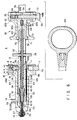
- FIG. 1A is a longitudinal sectional view of the forward end of a clip device according to a first embodiment of the invention
- FIG. 1B is a cross sectional view showing the forward end of the clip device.
- FIG. 2 is a perspective view of the operating section of a clip device.
- FIG. 4 is a side sectional view showing a configuration of an operating tube.
- FIG. 5A is a plan view of a clip
- FIG. 5B a side view of the clip.
- FIG. 6 is a sectional view of an operating unit of the clip device.
- FIG. 7 is a perspective view showing a configuration of the operating unit proper and a lid member.
- FIG. 8 is a perspective view showing a button for releasing a fixed state.
- FIG. 9 is a longitudinal sectional view showing the operating wire in coupled state with a wire support.
- FIG. 10 is a longitudinal sectional view of the release button in an assembled state.
- FIG. 11 is a perspective view showing a configuration of the base end of the operating wire.
- FIG. 12 is a longitudinal sectional view of a ratchet release button in an assembled state.
- FIG. 13 is a perspective view showing a cover member of a second slider.
- FIG. 14 is a sectional view showing the manner in which the tissue is bound using a clip device.
- FIG. 15A is a sectional view of a clip retained in the tissue to be bound
- FIG. 15B a cross sectional view of a clip device after a clip is retained
- FIG. 15C a longitudinal sectional view of a clip device after a clip is retained.
- FIG. 16 is a sectional view showing an operating unit of a clip device according to a second embodiment of the invention.
- FIG. 17 is a front sectional view showing the state of a caulked portion of the base end of the operating wire.
- FIG. 18 is a side sectional view showing a caulked portion of the base end of the operating wire.
- FIG. 19 is a diagram showing the essential parts of a caulking tool.
- FIGS. 20A and 20B are sectional views of a second slider.
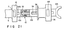
- FIG. 21 is a longitudinal side sectional view showing a coupling structure of the operating unit of a clip device according to a third embodiment of the invention.
- FIGS. 1 to 15 show a first embodiment of the invention.
- FIGS. lA and 1B show the forward end of a clip device as an endoscopic treatment tool, and FIG. 2 an operating unit 4 on the operator's side of the tool.
- this clip device includes a clip device proper 1 and a cassette-type clip unit 2 mounted replaceably on the clip device proper 1.
- numeral 3 designates a lead tube for the clip device proper 1.
- This lead tube 3 is formed of a flexible material such as ethylene tetrafluoride resin or the like and is adapted to be inserted into a body cavity using, for example, the channel of the endoscope.
- the operating unit 4 of the clip device proper 1 includes an operating unit proper 5, a first slider 13 mounted axially slidably on the operating unit proper 5, and a second slider 36 axially slidable with respect to the first slider 13 through a ratchet mechanism.
- the base end of the lead tube 3 is coupled to the operating unit proper 5 as described later.
- a flexible operating tube 28 having a coupling ring 29 of a stainless-steel short tube fixedly mounted at the forward end thereof is retractively inserted in the lead tube 3.
- this operating tube 28 is formed of densely-wound stainless-steel wires, for example, the base end of which is coupled to the first slider 13 of the operating unit 4. With the operation of the first slider 13, the operating tube 28 is caused to extend or retract in the lead tube 3 and also is adapted to protrude or withdraw through the forward-end opening of the lead tube 3.
- An operating wire 33 having a torque transmissivity is retractively inserted in the operating tube 28.
- This operating wire 33 is coated with fluororesin or the like material having a superior slidability over the entire length thereof, and the superior operability of the operating wire 33 is thereby maintained.
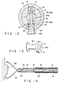
- FIG. 3A is a perspective view showing the hook 30 in enlarged form.
- the hook 30 has formed thereon a recess 30a on one side of the forward-end solid-cylindrical portion thereof.
- a pin 42 is erected from the recess 30a perpendicularly to the length of the hook 30.
- This pin 42 includes a circular head 42a and a neck 42b smaller in diameter than the head 42a.
- FIG. 3B is a sectional view taken in line IIIB-IIIB in FIG. 3A.
- a hole 40 coaxial with the longitudinal center axis of the hook 30 is formed in the base end of the hook 30.
- An operating wire 33 is inserted into and fixed by a fixing material or the like in the hole 40.
- the hook 30 is formed by metal injection molding. This is because a metal injection mold is superior in tenacity (toughness) to a machine-ground product, and should a force more than necessary be imposed on it, the mold is only deformed but not broken off from the wire 33.
- the lead tube 3 is desirably transparent so that the operating tube 28 inserted in the lead tube 3 is visible by endoscope from outside the lead tube 3.
- the clearance between the lead tube 3 and the operating tube 28 is preferably about 0.1 to 0.5 mm over the whole periphery. The reason is that an excessively large clearance would deform or buckle the tubes 3 and 28 while an excessively small clearance would increase the sliding resistance between the tubes 3 and 28.
- the operating tube 28 includes a forward-end coil 31 formed of a densely-wound stainless-steel wire of a rectangular section and having such an inner diameter that the hook 30 can be inserted in it, and a base-end coil 32 connected to the forward-end coil 31 by laser welding or the like process and having a densely-wound stainless-steel wire of a circular section.
- the forward-end coil 31 is formed flat in view of the need of securing such an inner diameter that the hook can be inserted in it.
- the flat-coil structure though thin in thickness, assures a durability against expansion and contraction and a high tenacity.
- the clearance between the base-end coil 32 of the operating tube 28 and the operating wire 33 inserted therein is set at a minimum. This clearance is desirably about 0.05 to 0.2 mm. This is in order to prevent the operating wire 33 from zigzagging within the base-end coil 32 and thereby adversely affecting the force-transmitting capability.
- the clip unit 2 includes a clip 45, a coupling plate 37 constituting a coupling member removably coupled to the clip 45, and a clip-fastening ring 46.
- the clip 45 is constructed of a thin band plate of stainless steel bent at the center thereof with the bent portion thereof making up a base end 47.
- a pair of loosely-fitted portions 48a, 48b spaced wider than the inner diameter of the clip-fastening ring 46 are extended from the base end 47. Further, the loosely-fitted portions 48a, 48b are so extended that arms 49a, 49b intersect each other. Furthermore, the forward end of the arms 49a, 49b forms holding sections 50a, 50b bent toward each other.
- the arms 49a, 49b of the clip 45 have a tendency to open the holding sections 50a, 50b.
- the coupling plate 37 is formed by punching a thin band plate of stainless steel, and has an end thereof formed with a J-shaped hook removably engaging the base end 47 of the clip 45 as shown in FIG. 5A.
- an engaging hole 52 is formed to removably engage the pin 42 (FIGS. 1A, 1B and 3A) of the hook 30 in the vicinity of the other end of the coupling plate 37.
- This engaging hole 52 includes a long hole portion 52a extending lengthwise and a large-diameter hole portion 52b formed at the end of the hole portion 52a nearer to the hook 51.
- the head 42a of the pin 42 of the hook 30 is formed smaller than the large hole portion 52b of the engaging hole 52 and larger than the width of the hole portion 52a.
- the neck 42b of the pin 42 is formed smaller in diameter than the width of the long hole portion 52a of the engaging hole 52.
- an unevenness is formed by a step on the outer peripheral surface of the clip-fastening ring 46.
- the small-diameter section 46a of the clip-fastening ring 46 formed by this step has an outer diameter smaller than the inner diameter of the coupling ring 29 of the operating tube 28 (FIG. 1) and is coupled by being fitted in the coupling ring 29.
- the outer diameter of the large-diameter section 46b of the clip-fastening ring 46 is thicker than the inner diameter of the coupling ring 29.
- the cassette-type clip unit 2 has the coupling plate 37 thereof inserted into the clip-fastening ring 46 from the large-diameter section 46b with the hook 51 of the coupling plate 37 engaged in the base end 47 of the clip 45.
- a fixing agent 90 such as silicon is filled in the clip-fastening ring 46, whereby the clip 45 and the coupling plate 37 are tacked in the clip-fastening ring 46.
- the operating unit 4 includes an operating unit proper 5, a first slider 13 slidably mounted in axial direction on the operating unit proper 5, and a second slider 36 slidable in axial direction through a ratchet mechanism with respect to the first slider 13.
- the operating unit 5 has formed over the entire length thereof a through hole 12 terminating with a forward-end opening 10 and a base-end opening 11. This through hole 12 communicates with the inner hole of the lead tube 3 connected to the forward-end opening 10 of the operating unit proper 5.
- a heat-contraction tube 27 of a comparatively soft material such as silicon is covered over the outer periphery of the forward-end socket 5a of the operating unit proper 5 from the outer periphery of the base end of the lead tube 3 (see also FIG. 2). This is in order to prevent the lead tube 3 from buckling due to an extreme alteration of the hardness at the connection between the lead tube 3 and the operating unit proper 5.
- the heat-contraction tube 27 functions as a reinforcing member for smoothing the hardness change from the lead tube 3 to the operating unit proper 5.
- the through hole 12 has a small-diameter portion 12a at the forward end thereof and a large-diameter portion 12b occupying a majority of the remaining portions.
- the small-diameter portion 12a and the large-diameter portion 12b are connected to each other through a tapered hole 12c.
- the large-diameter portion 12b is formed with such an inner diameter that the forward end of the first slider 13 can be inserted into it.
- the operating unit proper 5 has formed thereon a lure lock socket 14 onto which an injection cylinder not shown can be removably fitted and which communicates with the large-diameter portion 12b of the through hole 12.
- the operating unit proper 5 has a flange 15 at the base end thereof.
- a mount 94 on which a lid member 6 is adapted to be mounted is formed on the base end surface of the flange 15.
- Engaging grooves 16, 16 for engagement with the lid member 6 are formed respectively at the ends of the mount 94.
- an engaging member 17 adapted to engage a release button 7 shown in FIG. 8 is protruded from the base end surface of the mount 94.
- the engaging member 17 has on the outer surface thereof a side hole 18 communicating with the large-diameter portion 12b of the through hole 12 in the same direction as the grooves 16, 16.
- This side hole 18 includes a large-diameter hole portion 18a and a small-diameter hole portion 18b as shown in FIG. 10.
- the engaging member 17 is located at the center of the flange 15 coaxially with the operating unit proper 5.
- a base end opening 11 of the through hole 12 is formed at the base end surface of the engaging member 17.
- the lid member 6 presents a shape of a substantially circular disk, and has an end thereof formed with a groove 95 that can accommodate the mount 94 and the engaging member 17. This groove 95 reaches the peripheral edge of the lid member 6.
- the lid member 6 has a pair of protrusions 22, 22 protruded inward of the groove 95 in mesh with the grooves 16, 16 of the mount 94.
- the other end surface of the lid member 6 has formed thereon an opening 21 communicating with the groove 95 and adapted to engage the engaging member 17.
- the release button 7 includes a rectangular frame 25 adapted to slide in the space formed between the engaging member 17 and the lid member 6 with the operating unit proper 5 and the lid member 6 in an assembled state (the state shown in FIG. 10), and a pin 26 protruded inward of the frame 25.
- the pin 26 includes a large-diameter portion 26a fitted in the large-diameter hole portion 18a of the side hole 18 of the engaging member 17 and a small-diameter portion 26b fitted in the small-diameter hole portion 18b of the side hole 18.
- the total length of the pin 26 as assembled on the engaging member 17 is determined in such a manner as to extend a predetermined amount into the large-diameter portion 12b of the through hole 12 of the operating unit proper 5.
- the amount x of this extension is desirably given by the relation 0 mm ⁇ x ⁇ 2 mm.
- the release button 7 is assembled on the engaging member 17, and an O-ring 9 is interposed between the outer peripheral surface of the small-diameter portion 26b of the pin 26 and the peripheral surface of the large-diameter hole portion 18a of the side hole 18.
- a spring 8 is loaded in a spring mount hole 97 formed in the bottom of the large-diameter portion 26a of the pin 26. Under this condition, the lid member 6 is fitted in the operating unit proper 5. The fitting procedure will be described below.
- the cylindrical first slider 13 is retractively inserted in the through hole 12 of the operating unit proper 5.
- An operating tube 28 (base-end coil 32) inserted in the lead tube 3 is connected fixedly by brazing or the like means to the forward end of a metal coupling member 59 screwed to the forward end of the first slider 13 by a screw 60 through the forward-end opening 10 of the operating unit proper 5.
- the operating tube 28 is a coil which if fixed by an adhesive would undesirably expand or contract under the force exerted thereon and could undesirably separate the adhesive.
- the first slider 13 is made of a resin mold and therefore it is impossible to braze the operating tube 28 directly on the first slider 13. Consequently, the operating tube 28 should best be provisionally fixed by brazing or the like method on the metal coupling member 59 and then the screw 60 of the coupling member 59 is bonded by being forced into the first slider 13.
- a compression spring 62 is interposed between the screw 60 of the coupling member 59 and the operating unit proper 5.
- This compression spring 62 is forced into a spiral groove 61 formed in the outer peripheral surface of the coupling member 59 at the forward end of the screw 60.
- an adhesive is coated also on the compression spring 62 arranged in the spiral groove 61 at the time of the forced-in bonding of the first slider 13 and the coupling member 59, so that bonding work can be performed at the same time between the compression spring 62 and the coupling member 59 on the one hand and between the coupling member 59 and the first slider 13 on the other hand.
- Two guide slots 64, 64 are arranged along the length on the outer peripheral surface at the forward end side of the first slider 13. These two guide grooves 64, 64 are disposed at an angular interval of 180 degrees to each other along the peripheral direction.
- Each guide groove 64 has a width slightly larger than the diameter of the small-diameter portion 26b of the pin 26 of the release button 7 mounted on the operating unit proper 5.
- the forward end side of the guide groove 64 forms a shallow first guide groove portion 64a, and the base end side thereof constitutes a deep second guide groove portion 64b on both sides of a midway step 99 as a boundary.
- the pin 26 of the release button 7 is located at the forward end of the first guide groove portion 64a and also at the forward end of the second guide groove portion 64b of one guide groove 64, thereby restricting the amount by which the operating tube 28 is pulled into the lead tube 3 while at the same time restricting the rotation of the first slider 13.
- the compression spring 62 is dimensionally set in such a manner as to hold the compression force between the operating unit proper 5 and the first slider 13 when the pin 26 is placed in the second guide groove portion 64b on the second step and also to release the compression force when the pin 26 is located at the forward end of the first guide groove portion 64a on the first step.
- two guide grooves 64 are provided on the first slider 13 by reason of the fact that while the protrusion 7a of the release button 7 and the pin 26 are structurally located in opposite positions separate by 180 degrees from each other, the user may misunderstand that the pin 26 is located on the protrusion 7a of the release button 7 and thus may erroneously dispose the first slider 13 at a position 180° opposite with respect to the operating unit proper 5.
- a first slit 56 is formed along the longitudinal direction on the base end side of the first slider 13. Further, an expansion 13a expanding substantially perpendicular to the length of the first slider 13 from the two sides of the first slider 13 is formed at the forward end side of the first slit 56. This expansion 13a is formed with a second slit 57 perpendicular to the first slit 56.
- the second slider 36 is mounted movably along the first slit 56, and a rotative operation member 55 fixed as described later on the base end side of the operating wire 33 is arranged rotatably in the second slit 57. This configuration will be described in more detail with reference to FIG. 6.
- the operating wire 33 extends from the base end opening of the operating tube 28 fixedly connected at the forward end of the coupling member 59.
- This extended operating wire 33 is rotatably coupled to the second slider 36.
- a plurality of tubular members 34, 53 are fitted to cover the outer peripheral portion of the operating wire 33 extending from the base end opening of the operating tube 28.
- an operating pipe 34 made of a pipe material such as stainless steel is fitted to cover the outer periphery of the extension of the operating wire 33.
- a cylindrical wire support 35 made of stainless steel or the like material is fitted to cover the outer periphery of the base end of the operating wire 34.
- this fixing operation can of course be performed also by soldering.
- soldering may corrode off the operating wire 33 due to the residual flux or the like.
- many other problems are posed since such operations are required as the filing for removing extraneous solder and the cleaning process for removing flux. Taking these points into consideration, therefore, the fixing work by caulking is said to be preferable after all.
- a rotating pipe 53 is fitted to cover the outer periphery of the operating pipe 34 in spaced relationship with the wire support 35.
- This rotating pipe 53 is made of a pipe material such as brass and has a flat portion 54 over the substantially entire length thereof. In other words, this rotating pipe 53 has a D-shaped section.
- a disk-shaped rotative operation member 55 is slidably fitted on the outer periphery of the rotating pipe 53.
- a D-shaped through hole 58 having the same sectional shape as the rotating pipe 53 is formed at the central portion of the rotative operation member 55 to permit the turning effort of the rotative operation member 55 to be transmitted to the rotating pipe 53 (hence, also to the operating wire 33).
- the rotative operation member 55 cannot rotate with respect to the rotating member 53.
- the shape of the through hole 58 of the rotative operation member 55 of course also assumes a rectangular or hexagonal shape, as the case may be.
- nickel, chromium or the like is plated on the surface of the rotating pipe 53.
- the rotating pipe 53 is fixed on the operating pipe 34 by caulking the base end thereof.
- the fixing between the rotating pipe 53 and the operating pipe 34 may alternatively be accomplished by brazing or the like.
- the base end side of the operating wire 33 configured by being covered with the operating pipe 34 and the rotating pipe 53 in the above-mentioned manner is projected into the first slit 56 by being retractively inserted into the inner hole 120 of the first slider 13.
- This base end is fixed on the second slider 36, which is movable along the first slit 56, through the wire support 35.
- the rotative operation member 55 fitted on the outer periphery of the rotating pipe 53 is arranged in the second slit 57 formed in the expansion 13a of the first slider 53.
- the rotative operation member 55 is fitted slidably (but not rotatably as described above) on the outer periphery of the rotating pipe 53, and therefore the turning effort of the rotative operation member 55 can be transmitted to the rotating pipe 53 in any state of retraction of the rotating pipe 53.
- This turning effort is transmitted from the rotative operation member 55 to the rotating pipe 53 to the operating pipe 34 to the operating wire 33 to the hook 30 to the cassette-type clip 2.
- the direction in which the clip 45 of the cassette-type clip 2 is opened can be remotely controlled from outside the body.
- the rotative operation member 55 is arranged forward of the area where the second slide 36 slides. This is intended to facilitate the operation on the assumption that the second slider 36 is manipulated by the right hand and rotated by the left hand.
- the sliding section 65a has a relief 70 cut at the forward end thereof, and also has a pawl 71 protruded from the outer surface of the forward end thereof.
- the cover member 122 and the two holding members 65, 65 are fixed by pressing the coupled pair of the holding members 65, 65 into the inner hole 122a of the cover member 122 from the base end side of the cover member 122.
- the pawl 71 of the holding member 65, 65 is pressed in along a groove 72 (see FIG. 13) formed in the inner hole 122a of the cover member 122.
- This pressing operation is performed by taking advantage of the fact that the forward end of the sliding section 65a is displaced by the relief 70.
- the semicircular portion 65b of the holding member 65 is formed with a rectangular through hole 75 passing through the semicircular portion 65b in the perpendicular direction from the semicircular flat portion 74.
- This through hole 75 has arranged slidably therein a ratchet release button 68, an engaging means 66 and a spring 67.
- the spring 67 is arranged in a state compressed between the engaging means 66 and the inner wall of the second slider 36.
- the spring 67 causes the engaging means 66 to be pressed against the engaging pawl 76 of the first slider 13, thereby restricting the movement of the second slider 36 toward the forward end of the first slider 13.
- the engaging means 66 and the engaging pawl 76 constitute a ratchet mechanism.
- the ratchet release button 68 is passed through the through hole 75 and the through hole 77 of the cover member 122 communicating with the through hole 75. Upon depression of the ratchet release button 68, the engaging means 66 is pushed up and releases the engagement between the engaging means 66 and the engaging pawl 76.
- the J-shaped hook 51 of the cassette-type clip 2 is extended by pulling the second slider 36 toward the operator, and in this way the cassette-type clip 2 and the clip device proper 1 are separated from each other thereby to retain the cassette-type clip 2 in the affected part.
- the force thus far exerted on the second slider 36 is released, so that the second slider 36 abruptly moves toward the operator with the result that the base end of the second slider 36 and the base end of the first slit 56 of the first slider 13 come to strike violently each other.
- the base end of the holding members 65, 65 is undesirably subjected to plastic deformation, and the through hole 75 is crushed, thus preventing the engaging means 66 and the sliding section 68a of the ratchet release button 68 from smooth sliding.
- the clearance between the sliding section 68a and the through hole 75 is minimized to eliminate the space which otherwise might be available for the plastic deformation of the holding members 65, 65.
- the holding members 65, 65 thus absorb the impact by elastic deformation, thereby permitting the engaging means 66 and the sliding section 68a of the ratchet release button 68 to smoothly slide. Also, the two holding members 65, 65 are surrounded by the cylindrical cover member 122 to prevent the holding members 65, 65 from being dislocated due to the collision.
- the ratchet release button 68 includes a stopper 78 adapted to expand toward the button 68b. By displacing the space 79 inside the stopper 78, the ratchet release button 68 can be fitted in the through hole 75 of the holding members 65, 65. Also, the ratchet release button 68, after being thus fitted, is prevented from coming off as the stopper 78 engages the step 80 of the through hole 75.
- annular handle 105 is provided at the base end of the first slider 13.
- the operation of the clip device configured as described above will be explained.
- the first slider 13 of the operating unit 4 is pushed out toward the forward end thereof, whereby the pin 26 is located in the second guide groove portion 64b of the first slider 13 thereby to project the operating tube 28 from the lead tube 3.
- the cassette-type clip unit 2 is mounted on the hook 30 on the side of the clip device proper 1.
- the second slider 36 of the operating unit 4 is slid toward the forward, end thereof and the hook 30 at the forward end of the operating wire 33 is projected outside of the operating tube 28.
- a head 42a of the pin 42 of the hook 3 is fitted in the large-diameter hole 52b of the coupling plate 37 of the clip unit 2, and under this condition the clip unit 2 is pulled toward the forward end.
- the slot portion 52a of the engaging hole 52 of the coupling plate 37 is fitted on the neck 42b of the pin 42 of the hook 30, and thus is settled in position not to easily come off.
- the second slider 36 of the operating unit 4 is pulled toward the operator, and the hook 30 is retracted into the coupling ring 29 through the operating wire 33.
- the coupler 46a of the clip-fastening ring 46 on the side of the cassette-type clip unit 2 is fixedly fitted in the coupling ring 29. As a result, the cassette-type clip unit 2 is loaded in the clip device proper 1.
- the first slider 13 of the operating unit 4 is slid toward the operator and thus the operating tube 28 is pulled into the lead tube 3.
- the operating tube 28 thus is accommodated in the lead tube 3 with the clip 45 closed.
- the operating tube 28, together with the lead tube 3, is thus led into the vital body cavity through the endoscope channel, after which the first slider 13 of the operating unit 4 is pushed out toward the forward end.
- the operating tube 28 thus pushed out of the lead tube 3, thereby projecting the clip 45 out of the lead tube 3.
- the arms 49a, 49b of the clip 45 which have the inherent tendency of widening open, open widely.
- the second slider 36 of the operating unit 4 is pulled toward the operator, and the hook 30 thus is also pulled toward the operator through the operating wire 33.
- the loosely-fitted portions 48a, 48b of the clip 45 are retracted into the clip-fastening ring 46.
- the loosely-fitted portions 48a, 48b are crushed, with the result that the arms 49a, 49b of the clip 45 open to the widest degree.
- the rotative operation member 55 is rotated in an arbitrary direction thereby to orient the clip 45 in the desired leg-open direction.
- the operating wire 33 can be more smoothly rotated by the rotative operation member 55. This is by reason of the fact that the operating wire 33 is tensioned in order to open wide the clip 45, and with the friction resistance between the clip unit 2 and the coupling ring 29 increased by this tension, the operating wire 33 is fixed by ratchet. By returning the second slider 36 several ratchets toward the forward end, however, the tension can be released.
- the clip 45 is pressed against the vital tissue 108 requiring the clipping operation.
- the second slider 36 is pulled toward the operator again, and the operating wire 33 thus pulled also toward the operator.
- the arms 49a, 49b of the clip 45 strike the clip-fastening ring 46, and further are pulled into the clip-fastening ring 46, so that the arms 49a, 49b of the clip 45 are closed and the holders 50a, 50b hold the vital tissue 108 tightly between them.
- the clip 45 is struck deep into the vital tissue 108 as shown in FIG. 15A.
- the hook 51 of the coupling plate 37 is extended as shown FIGS. 15B and 15C and the clip 45 comes off from the coupling plate 37.
- the clip-fastening ring 46 which presses the arms 49a, 49b of the clip 45, does not come off from the clip 45 as shown in FIG. 15A and is retained in the body together with the clip 45.
- the forward-end treatment section can be rotated without adversely affecting the mechanisms for other than the rotation. Further, rotation can be accomplished in both directions securely without any skip or similar irregularities. As a result, the clipping work is done easily.
- FIGS. 16 to 20 show a second embodiment of the invention. As shown in FIG. 16, according to this embodiment, the only difference from the first embodiment lies in the construction of the second slider and the fixed state of the base end of the wire 33, while the other configurations are identical to those of the first embodiment.
- the length of the engaging means 66 along the length of the first and second sliders 13, 36 is shorter by about 5 mm than the length of the through hole 75 along the length of the first and second sliders 13, 36.
- the second slider 36 is adapted to move by about 3 to 10 mm, or preferably, by about 5 mm, with respect to the first slider 13.
- the fixedly-caulking operation is accomplished by a caulking device having a caulking section 102 as shown in FIG. 19.
- the caulking section 102 includes a recessed support 100 and a protruded portion 101.
- the side of the wire support 35' is held between the support 100 and the protruded portion 101 to perform the caulking work.
- the operating wire 33 and the operating pipe 34 are sided to the support 100 of the caulking section 102.
- the caulking process is effected at two pints on the side displaced in the longitudinal direction of the wire support 35'.
- the caulking operation at the two points is carried out with the caulking section 102 oriented in different directions.
- the caulking work at the two points increases the strength of securing the operating pipe 34 and the operating wire 33 to each other by means of a corrugation formed thereon.
- the distance between the two caulking points 91, 91 is desirably about 0.5 mm. This is because an excessively short interval between the two caulking points 91, 91 would cause an excessively bent condition of the operating pipe 34, which in turn would lead to a breakage initiated at the bent part.
- the fixing strength fails to reach a sufficiently high level.
- the caulking operation may of course be performed at three or more points. In this case, too, however, adjacent caulking points 91, 91 are required to be caulked in opposite directions.
- the second slider 36 is moved about 3 to 10 mm, or preferably about 5 mm, toward the forward end.
- the rotative operation member 55 (the operating wire 33) can be more smoothly rotated.
- the tension imposed on the operating wire 33 for opening the legs of the clip 45 (the state shown in FIG. 20A) can be released by moving the second slider 36 by about 3 to 10 mm or preferably by about 5 mm toward the forward end (the state shown in FIG. 20B).
- this movement of 3 to 10 mm or preferably about 5 mm can be accomplished with the ratchet mechanism turned on.
- the same effect of operation can be obtained as the first embodiment.
- the second slider 36 can be moved by about 3 to 10 mm or preferably by about 5 mm toward the forward end without releasing the ratchet before rotation. The tension exerted on the wire thus can be released safely and securely, thus permitting a smoother rotation.
- the wire support 35 is caulked in such a manner that the operating pipe 34 and the operating wire 33 are corrugated appropriately, a low-cost fixing arrangement is possible with a high fixing strength.
- FIG. 21 shows a third embodiment of the invention. This embodiment is different from the first embodiment in that the first slider 13 is split into two parts at the base end side of the second guide slot 64b.
- the first slider 13 includes a forward-end slider portion 13a adapted to slide in the operating unit proper 5 and connected to the operating tube 28 and a base-side slider portion 13b having a first slit 56 and rotatably coupled to the forward-end slider portion 13a.
- the operating wire 33 is rotatably connected to the second slider 36 together with the operating pipe 34 fitted to cover the outer periphery thereof.
- the present embodiment does not include the rotating pipe 53, the rotative operation member 55 and the second slit 57.
- the other configuration of the embodiment is identical to that of the first embodiment.
Landscapes
- Health & Medical Sciences (AREA)
- Life Sciences & Earth Sciences (AREA)
- Surgery (AREA)
- Engineering & Computer Science (AREA)
- Public Health (AREA)
- Veterinary Medicine (AREA)
- Biomedical Technology (AREA)
- Heart & Thoracic Surgery (AREA)
- Medical Informatics (AREA)
- Molecular Biology (AREA)
- Animal Behavior & Ethology (AREA)
- General Health & Medical Sciences (AREA)
- Nuclear Medicine, Radiotherapy & Molecular Imaging (AREA)
- Pathology (AREA)
- Ophthalmology & Optometry (AREA)
- Physics & Mathematics (AREA)
- Plasma & Fusion (AREA)
- Otolaryngology (AREA)
- Reproductive Health (AREA)
- Vascular Medicine (AREA)
- Oral & Maxillofacial Surgery (AREA)
- Cardiology (AREA)
- Endoscopes (AREA)
- Surgical Instruments (AREA)
- Instruments For Viewing The Inside Of Hollow Bodies (AREA)
Abstract
Claims (11)
- Outil de traitement endoscopique adapté pour être conduit à l'intérieur du corps vital par l'intermédiaire du canal d'endoscope et pour opérer une section de traitement (45) en transmettant la force d'opération d'une section d'opération (4, 13, 36, 55) du côté de l'opérateur à la section de traitement, comprenant :caractérisé en ce qu'il comprend en outre :une gaine tubulaire (28) adaptée pour être insérée dans le canal endoscopique ;un moyen d'opération rotatif (55) disposé sur ladite section d'opération pour opérer de manière rotative ladite section de traitement ; etun fil d'opération rotatif (33) inséré dans ladite gaine (28) pour coupler ladite section de traitement (45) audit moyen d'opération rotatif (55) et comportant un couple de transmissivité capable de transmettre le couple de rotation du moyen d'opération rotatif 55 à ladite section de traitement (45),un tube en plomb (3) adapté pour être inséré dans le canal endoscopique, ladite gaine (28) étant insérée de manière rétractive dans ledit tube en plomb (3) ;un premier coulisseau (13) connecté à l'extrémité de base de ladite gaine (28) pour réaliser l'opération de va et vient de ladite gaine (28) par rapport audit tube en plomb (3) ; etun deuxième coulisseau (36) connecté à l'extrémité de base dudit fil d'opération (33) et mettant en prise ledit premier coulisseau (13) par l'intermédiaire d'un mécanisme d'encliquetage (66, 76) pour réaliser l'opération de va et vient du fil d'opération (33) tout en reculant et avançant par rapport au premier coulisseau (13).
- Outil de traitement endoscopique selon la revendication 1, caractérisé en ce que ledit mécanisme d'encliquetage (66, 76) comprend un cliquet de mise en prise (76) formé le long de la direction longitudinale dudit premier coulisseau (13), un moyen de mise en prise (66) disposé dans ledit deuxième coulisseau (36) et adapté pour se mettre en prise avec ledit cliquet de mise en prise (76), un ressort (67) pour appliquer ledit moyen de mise en prise (66) contre ledit cliquet de mise en prise (76), et un bouton de relâchement (68) pour relâcher la mise en prise entre ledit moyen de mise en prise (66) et ledit cliquet de mise en prise (76) contre la force d'application dudit ressort (67) .
- Outil de traitement endoscopique selon la revendication 2, caractérisé en ce que ledit bouton de relâchement (68) est disposé de manière coulissable dans ledit deuxième coulisseau (13), et le jeu entre ledit bouton de relâchement (68) et ledit deuxième coulisseau (36) dans la direction d'avance et de recul dudit deuxième coulisseau est de 0,01 à 0,2 mm.
- Outil de traitement endoscopique selon la revendication 2, caractérisé en outre en ce qu'il comprend un moyen de relâchement de tension capable de relâcher la tension dudit fil d'opération (33) en avançant et en retirant ledit deuxième coulisseau (36) par rapport audit premier coulisseau (13) tout en maintenant en prise ledit premier coulisseau (13) et ledit deuxième coulisseau (36) par l'encliquetage (66, 76).
- Outil de traitement endoscopique selon la revendication 4, caractérisé en ce que le moyen de mise en prise (66) est disposé dans ledit deuxième coulisseau (36) retenant un jeu prédéterminé.
- Outil de traitement endoscopique selon la revendication 5, caractérisé en ce que ledit jeu est de 4 à 6 mm.
- Outil de traitement endoscopique selon la revendication 1, caractérisé en ce qu'un tube de renforcement (34) est disposé de manière externe au niveau de l'extrémité de base dudit fil d'opération (33), un élément de support cylindrique (35') est disposé de manière externe sur la périphérie externe dudit tube de renforcement (34), le côté de l'élément de support (35') est calfeutré en au moins deux points (91) dans la direction longitudinale, d'où il résulte que ledit fil d'opération (33), ledit tube de renforcement (34) et ledit élément de support (35') sont fixés de manière solidaire, ledit élément de support (35') est saisi dans une section de mise en prise (69) disposée dans ledit deuxième coulisseau (36), d'où il résulte que ledit fil d'opération (33) et ledit deuxième coulisseau (36) sont mutuellement couplés de manière rotative.
- Outil de traitement endoscopique selon la revendication 7, caractérisé en ce que lesdites opérations de calfeutrage adjacentes sont réalisées sur les côtés opposés dudit élément de support (35').
- Outil de traitement endoscopique selon la revendication 7, caractérisé en ce que ledit élément de support (35') est calfeutré par un élément de calfeutrage (100, 101, 102) qui comprend un premier bras (101) présentant une protrusion et un deuxième bras (100) présentant un creux, situé à l'opposé de la protrusion, pour recevoir la protrusion, le premier bras et le deuxième bras étant connectés l'un à l'autre de manière rotative.
- Outil de traitement endoscopique selon la revendication 7, caractérisé en ce que la direction longitudinale par laquelle les points de calfeutrage adjacents (91) sont espacés mutuellement est de 0,4 à 0,6 mm.
- Outil de traitement endoscopique selon l'une quelconque des revendications 1 à 10, caractérisé en ce que ladite section de traitement (45) est une pince (45) rotative par rapport à ladite gaine (28) et adaptée pour s'ouvrir large, en raison de la tendance de large ouverture inhérente à celle-ci, ladite pince (45) étant adaptée pour être mise en prise de manière remplaçable avec un crochet (30) monté au niveau de l'extrémité avant dudit fil d'opération (33) et pour se fermer en étant rétracté dans un tube de maintien (46) monté de manière remplaçable au niveau de l'extrémité avant de ladite gaine (28) par l'opération de retrait dudit fil d'opération (33).
Applications Claiming Priority (7)
| Application Number | Priority Date | Filing Date | Title |
|---|---|---|---|
| JP6269362A JPH08126648A (ja) | 1994-11-02 | 1994-11-02 | 内視鏡用処置具 |
| JP269362/94 | 1994-11-02 | ||
| JP26936294 | 1994-11-02 | ||
| JP8828195 | 1995-04-13 | ||
| JP88281/95 | 1995-04-13 | ||
| JP08828195A JP3523712B2 (ja) | 1995-04-13 | 1995-04-13 | 結紮装置 |
| PCT/JP1995/002244 WO1996014020A1 (fr) | 1994-11-02 | 1995-11-02 | Instrument fonctionnant avec un endoscope |
Publications (3)
| Publication Number | Publication Date |
|---|---|
| EP0738501A1 EP0738501A1 (fr) | 1996-10-23 |
| EP0738501A4 EP0738501A4 (fr) | 1997-05-07 |
| EP0738501B1 true EP0738501B1 (fr) | 2000-05-24 |
Family
ID=26429689
Family Applications (1)
| Application Number | Title | Priority Date | Filing Date |
|---|---|---|---|
| EP95936088A Expired - Lifetime EP0738501B1 (fr) | 1994-11-02 | 1995-11-02 | Instrument fonctionnant avec un endoscope |
Country Status (4)
| Country | Link |
|---|---|
| US (1) | US5766184A (fr) |
| EP (1) | EP0738501B1 (fr) |
| DE (1) | DE69517153T2 (fr) |
| WO (1) | WO1996014020A1 (fr) |
Cited By (9)
| Publication number | Priority date | Publication date | Assignee | Title |
|---|---|---|---|---|
| US8152822B2 (en) | 2006-12-05 | 2012-04-10 | Cook Medical Technologies Llc | Combination therapy hemostatic clip |
| US8291915B2 (en) | 1997-03-04 | 2012-10-23 | Tyco Healthcare Group Lp | Method and apparatus for treating venous insufficiency using directionally applied energy |
| US8425412B2 (en) | 2006-07-14 | 2013-04-23 | Cook Medical Technologies Llc | Papilla spreader |
| US8435235B2 (en) | 2007-04-27 | 2013-05-07 | Covidien Lp | Systems and methods for treating hollow anatomical structures |
| US8764774B2 (en) | 2010-11-09 | 2014-07-01 | Cook Medical Technologies Llc | Clip system having tether segments for closure |
| US9192381B2 (en) | 2007-03-15 | 2015-11-24 | Covidien Lp | Surgical stapling apparatus with powered articulation |
| US9370361B2 (en) | 2005-06-03 | 2016-06-21 | Covidien Lp | Surgical stapler with timer and feedback display |
| US9585659B2 (en) | 2005-06-03 | 2017-03-07 | Covidien Lp | Battery powered surgical instrument |
| US10143479B2 (en) | 2001-10-05 | 2018-12-04 | Boston Scientific Scimed, Inc. | Device and method for through the scope endoscopic hemostatic clipping |
Families Citing this family (174)
| Publication number | Priority date | Publication date | Assignee | Title |
|---|---|---|---|---|
| US5902290A (en) * | 1994-03-14 | 1999-05-11 | Advanced Cardiovascular Systems, Inc. | Catheter providing intraluminal access |
| US6139527A (en) * | 1996-03-05 | 2000-10-31 | Vnus Medical Technologies, Inc. | Method and apparatus for treating hemorrhoids |
| US6036687A (en) | 1996-03-05 | 2000-03-14 | Vnus Medical Technologies, Inc. | Method and apparatus for treating venous insufficiency |
| US6033397A (en) * | 1996-03-05 | 2000-03-07 | Vnus Medical Technologies, Inc. | Method and apparatus for treating esophageal varices |
| CA2248260C (fr) | 1996-03-05 | 2010-11-16 | Michael D. Laufer | Systeme utilisant un catheter vasculaire pour rechauffer des tissus |
| US6152899A (en) | 1996-03-05 | 2000-11-28 | Vnus Medical Technologies, Inc. | Expandable catheter having improved electrode design, and method for applying energy |
| US5746753A (en) * | 1996-05-13 | 1998-05-05 | Boston Scientific Corporation | Needle grasping apparatus |
| JP3417778B2 (ja) * | 1997-01-17 | 2003-06-16 | ペンタックス株式会社 | 内視鏡用処置具 |
| JP4229491B2 (ja) | 1997-07-16 | 2009-02-25 | オリンパス株式会社 | 手術用処置具 |
| US6401719B1 (en) | 1997-09-11 | 2002-06-11 | Vnus Medical Technologies, Inc. | Method of ligating hollow anatomical structures |
| US6179832B1 (en) | 1997-09-11 | 2001-01-30 | Vnus Medical Technologies, Inc. | Expandable catheter having two sets of electrodes |
| US6258084B1 (en) | 1997-09-11 | 2001-07-10 | Vnus Medical Technologies, Inc. | Method for applying energy to biological tissue including the use of tumescent tissue compression |
| US6200312B1 (en) | 1997-09-11 | 2001-03-13 | Vnus Medical Technologies, Inc. | Expandable vein ligator catheter having multiple electrode leads |
| US6014589A (en) * | 1997-11-12 | 2000-01-11 | Vnus Medical Technologies, Inc. | Catheter having expandable electrodes and adjustable stent |
| DE19755974C2 (de) * | 1997-12-16 | 1999-10-28 | Fraunhofer Ges Forschung | Vorrichtung und Verfahren zur Gewinnung von 3D-Ultraschalldaten |
| US5931844A (en) * | 1998-03-31 | 1999-08-03 | Smith & Nephew, Inc. | Surgical drive tool |
| JP3733580B2 (ja) * | 1998-04-06 | 2006-01-11 | ニプロ株式会社 | 欠損閉塞用閉鎖栓回収具 |
| JP3370601B2 (ja) * | 1998-05-28 | 2003-01-27 | ペンタックス株式会社 | 内視鏡用処置具の操作部 |
| US6514261B1 (en) * | 1998-09-30 | 2003-02-04 | Impra, Inc. | Delivery mechanism for implantable stent |
| US6162209A (en) * | 1998-11-17 | 2000-12-19 | Scimed Life Systems, Inc. | Multi-function surgical instrument tool actuator assembly |
| JP3704248B2 (ja) * | 1999-02-04 | 2005-10-12 | ペンタックス株式会社 | 内視鏡用操作ワイヤの連結構造 |
| JP3917332B2 (ja) * | 1999-08-04 | 2007-05-23 | ペンタックス株式会社 | 内視鏡用処置具の操作ワイヤ連結部 |
| JP2001046392A (ja) * | 1999-08-04 | 2001-02-20 | Asahi Optical Co Ltd | 内視鏡用処置具の連結部 |
| US6258064B1 (en) | 1999-10-04 | 2001-07-10 | Syntheon, Llc | Helically advanceable endoscopic needle device |
| US6428548B1 (en) | 1999-11-18 | 2002-08-06 | Russell F. Durgin | Apparatus and method for compressing body tissue |
| US6911032B2 (en) | 1999-11-18 | 2005-06-28 | Scimed Life Systems, Inc. | Apparatus and method for compressing body tissue |
| JP4166414B2 (ja) * | 2000-05-17 | 2008-10-15 | オリンパス株式会社 | 内視鏡用処置具 |
| DE10038576C1 (de) * | 2000-08-03 | 2002-05-02 | Storz Karl Gmbh & Co Kg | Medizinisches Instrument mit abnehmbarem Werkzeug |
| US6585694B1 (en) * | 2000-09-07 | 2003-07-01 | Syntheon, Llc | Knob-controlled endoscopic needle device |
| US6743185B2 (en) * | 2000-09-26 | 2004-06-01 | Scimed Life Systems, Inc. | Handle assembly for surgical instrument and method of making the assembly |
| WO2002041931A2 (fr) * | 2000-11-27 | 2002-05-30 | Medtronic, Inc. | Tuteurs et procedes de preparation de tuteurs a partir de fils recouverts de couches de revetement hydrogel |
| DE10064623C1 (de) * | 2000-12-22 | 2002-08-22 | Winter & Ibe Olympus | Zange für endoskopische Chirurgie |
| US20020087151A1 (en) * | 2000-12-29 | 2002-07-04 | Afx, Inc. | Tissue ablation apparatus with a sliding ablation instrument and method |
| JP2002224124A (ja) * | 2001-02-06 | 2002-08-13 | Olympus Optical Co Ltd | 結紮装置 |
| EP2221011B8 (fr) * | 2001-02-08 | 2012-02-29 | Tyco Healthcare Group LP | Instrument chirurgical ultrasonique |
| JP4059656B2 (ja) * | 2001-03-07 | 2008-03-12 | オリンパス株式会社 | 生体組織のクリップ装置 |
| US20050021123A1 (en) * | 2001-04-30 | 2005-01-27 | Jurgen Dorn | Variable speed self-expanding stent delivery system and luer locking connector |
| US6991634B2 (en) * | 2001-05-23 | 2006-01-31 | Pentax Corporation | Clip device of endoscope |
| US10285694B2 (en) | 2001-10-20 | 2019-05-14 | Covidien Lp | Surgical stapler with timer and feedback display |
| CA2433040A1 (fr) * | 2001-10-24 | 2003-05-01 | John J. Damarati | Systeme de pinces hemostatiques multiples pour endoscope |
| US7122028B2 (en) * | 2001-12-19 | 2006-10-17 | Allegiance Corporation | Reconfiguration surgical apparatus |
| EP1329201B1 (fr) * | 2002-01-21 | 2004-11-10 | Karl Storz GmbH & Co. KG | Instrument medical pour la chirurgie à caractère invasif minimum à assistance manuelle |
| EP1494599A1 (fr) * | 2002-04-15 | 2005-01-12 | Wilson-Cook Medical Inc. | Dispositif de pose d'agrafes avec moyen de rin age |
| WO2003090630A2 (fr) | 2002-04-25 | 2003-11-06 | Tyco Healthcare Group, Lp | Instruments chirurgicaux comprenant des dispositifs microelectromecaniques |
| US20050085829A1 (en) * | 2002-05-17 | 2005-04-21 | Esophyx, Inc. | Transoral endoscopic gastroesophageal flap valve restoration device, assembly, system and method |
| JP3748421B2 (ja) * | 2002-07-03 | 2006-02-22 | 株式会社ベクトロニクス | 医療用遠隔操作器具 |
| JP4109030B2 (ja) * | 2002-07-19 | 2008-06-25 | オリンパス株式会社 | 生体組織のクリップ装置 |
| JP4145149B2 (ja) * | 2003-01-17 | 2008-09-03 | オリンパス株式会社 | 生体組織のクリップ装置 |
| JP3923022B2 (ja) * | 2003-02-28 | 2007-05-30 | オリンパス株式会社 | 内視鏡用処置具 |
| KR101078544B1 (ko) * | 2003-03-17 | 2011-11-01 | 스미또모 베이크라이트 가부시키가이샤 | 클립 및 생체 조직의 클립 장치 |
| DE60312050T2 (de) | 2003-05-09 | 2007-10-25 | Tyco Healthcare Group Lp, Norwalk | Anastomoseklammer mit fluidabgabe-kapillare |
| US20040260199A1 (en) * | 2003-06-19 | 2004-12-23 | Wilson-Cook Medical, Inc. | Cytology collection device |
| WO2005004730A1 (fr) * | 2003-06-19 | 2005-01-20 | Wilson-Cook Medical, Inc. | Poignee pour dispositifs medicaux, et ensembles de dispositifs medicaux comportant une poignee |
| JP4056989B2 (ja) * | 2003-06-24 | 2008-03-05 | オリンパス株式会社 | 内視鏡処置具 |
| CA2539979C (fr) | 2003-09-30 | 2011-11-29 | Scimed Life Systems, Inc. | Pince de relachement de l'element de tension a travers l'endoscope |
| JP4578817B2 (ja) * | 2004-02-06 | 2010-11-10 | オリンパス株式会社 | 外科手術用病変部同定システム |
| US20050228312A1 (en) * | 2004-03-31 | 2005-10-13 | Vihar Surti | Biopsy needle system |
| US20050251178A1 (en) * | 2004-05-03 | 2005-11-10 | Tirabassi Michael V | Hooked rod delivery system for use in minimally invasive surgery |
| US8123762B2 (en) | 2004-08-19 | 2012-02-28 | Boston Scientific Scimed, Inc. | Suturing instrument |
| WO2006068154A1 (fr) | 2004-12-24 | 2006-06-29 | Olympus Corporation | Dispositif d’aiguille a injection pour realiser une injection dans un tissu humain situe dans une cavite corporelle |
| AU2006206544B2 (en) * | 2005-01-20 | 2010-08-26 | Cook Medical Technologies Llc | Biopsy forceps |
| JP4763307B2 (ja) * | 2005-02-18 | 2011-08-31 | オリンパス株式会社 | 内視鏡用処置具 |
| EP1879520B1 (fr) | 2005-05-09 | 2013-03-13 | Angiomed GmbH & Co. Medizintechnik KG | Dispositif de mise en place d'un implant |
| US7762960B2 (en) | 2005-05-13 | 2010-07-27 | Boston Scientific Scimed, Inc. | Biopsy forceps assemblies |
| US11291443B2 (en) | 2005-06-03 | 2022-04-05 | Covidien Lp | Surgical stapler with timer and feedback display |
| JP4777012B2 (ja) | 2005-08-11 | 2011-09-21 | オリンパスメディカルシステムズ株式会社 | 医療用処置具 |
| JP2009504345A (ja) | 2005-08-17 | 2009-02-05 | シー・アール・バード・インコーポレーテッド | 可変速度ステント送達システム |
| US20070072466A1 (en) * | 2005-09-27 | 2007-03-29 | Manabu Miyamoto | Instrument for endoscope |
| US7647829B2 (en) * | 2005-11-28 | 2010-01-19 | Westinghouse Electric Co. Llc | Steam generator nondestructive examination method |
| US20070135802A1 (en) * | 2005-12-14 | 2007-06-14 | Olympus Medical Systems Corp. | Method of lifting diseased part, tissue lifting system, and indwelling tool |
| US11026822B2 (en) | 2006-01-13 | 2021-06-08 | C. R. Bard, Inc. | Stent delivery system |
| EP1971299B1 (fr) | 2006-01-13 | 2014-07-16 | C.R. Bard, Inc. | Système de pose de stent |
| AU2007225266B2 (en) * | 2006-03-10 | 2013-06-06 | Cook Medical Technologies Llc | A clip device and a protective cap for drawing the target tissue into it before the clip is deployed |
| US7998167B2 (en) * | 2006-04-14 | 2011-08-16 | Ethicon Endo-Surgery, Inc. | End effector and method of manufacture |
| US20070244513A1 (en) * | 2006-04-14 | 2007-10-18 | Ethicon Endo-Surgery, Inc. | Endoscopic device |
| US7857827B2 (en) * | 2006-04-14 | 2010-12-28 | Ethicon Endo-Surgery, Inc. | Endoscopic device |
| US8313500B2 (en) * | 2006-04-14 | 2012-11-20 | Ethicon Endo-Surgery, Inc. | Endoscopic device |
| ATE518484T1 (de) * | 2006-05-31 | 2011-08-15 | Covidien Ag | Medizinisches nahtinstrument mit greifvorrichtung |
| EP2020925B1 (fr) * | 2006-06-01 | 2013-07-10 | Cook Medical Technologies LLC | Mécanismes de libération d'un dispositif d'agrafe |
| GB0615658D0 (en) | 2006-08-07 | 2006-09-13 | Angiomed Ag | Hand-held actuator device |
| US8529597B2 (en) * | 2006-08-09 | 2013-09-10 | Coherex Medical, Inc. | Devices for reducing the size of an internal tissue opening |
| US9138208B2 (en) | 2006-08-09 | 2015-09-22 | Coherex Medical, Inc. | Devices for reducing the size of an internal tissue opening |
| US20090270840A1 (en) * | 2008-03-28 | 2009-10-29 | Coherex Medical, Inc. | Delivery systems for a medical device and related methods |
| US8167894B2 (en) * | 2006-08-09 | 2012-05-01 | Coherex Medical, Inc. | Methods, systems and devices for reducing the size of an internal tissue opening |
| US8733614B2 (en) | 2006-10-06 | 2014-05-27 | Covidien Lp | End effector identification by mechanical features |
| US20080255413A1 (en) | 2007-04-13 | 2008-10-16 | Michael Zemlok | Powered surgical instrument |
| US7950560B2 (en) | 2007-04-13 | 2011-05-31 | Tyco Healthcare Group Lp | Powered surgical instrument |
| US8800837B2 (en) | 2007-04-13 | 2014-08-12 | Covidien Lp | Powered surgical instrument |
| US11259802B2 (en) | 2007-04-13 | 2022-03-01 | Covidien Lp | Powered surgical instrument |
| EP1985329B1 (fr) | 2007-04-25 | 2010-06-02 | Olympus Medical Systems Corp. | Élément tubulaire et instrument endoscopique |
| US7823760B2 (en) | 2007-05-01 | 2010-11-02 | Tyco Healthcare Group Lp | Powered surgical stapling device platform |
| US8162959B2 (en) | 2007-05-03 | 2012-04-24 | Boston Scientific Scimed, Inc. | Single stage hemostasis clipping device |
| US7931660B2 (en) | 2007-05-10 | 2011-04-26 | Tyco Healthcare Group Lp | Powered tacker instrument |
| US8663221B2 (en) * | 2007-06-08 | 2014-03-04 | Olympus Medical Systems Corp. | Endoscopic treatment tool |
| GB0713497D0 (en) | 2007-07-11 | 2007-08-22 | Angiomed Ag | Device for catheter sheath retraction |
| US20090105798A1 (en) * | 2007-10-17 | 2009-04-23 | Abbott Laboratories Vascular Enterprises Limited | Handle for stepwise deployment |
| US7922063B2 (en) | 2007-10-31 | 2011-04-12 | Tyco Healthcare Group, Lp | Powered surgical instrument |
| WO2009079509A2 (fr) * | 2007-12-18 | 2009-06-25 | Boston Scientific Scimed, Inc. | Dispositif médical multifonctions |
| EP2252228B1 (fr) * | 2008-03-12 | 2016-11-02 | AFreeze GmbH | Manche pour dispositif d'ablation |
| EP2113208A3 (fr) * | 2008-05-02 | 2010-01-20 | Fujifilm Corporation | Dispositif à fixations multiples et appareil d'application à fixations multiples |
| US9770297B2 (en) | 2008-06-04 | 2017-09-26 | Covidien Lp | Energy devices and methods for treating hollow anatomical structures |
| AU2009282596A1 (en) | 2008-08-19 | 2010-02-25 | Wilson-Cook Medical Inc. | Apparatus for removing lymph nodes or anchoring into tissue during a translumenal procedure |
| US9332973B2 (en) | 2008-10-01 | 2016-05-10 | Covidien Lp | Needle biopsy device with exchangeable needle and integrated needle protection |
| US11298113B2 (en) | 2008-10-01 | 2022-04-12 | Covidien Lp | Device for needle biopsy with integrated needle protection |
| US9186128B2 (en) | 2008-10-01 | 2015-11-17 | Covidien Lp | Needle biopsy device |
| US8968210B2 (en) | 2008-10-01 | 2015-03-03 | Covidien LLP | Device for needle biopsy with integrated needle protection |
| US9782565B2 (en) | 2008-10-01 | 2017-10-10 | Covidien Lp | Endoscopic ultrasound-guided biliary access system |
| US20100145362A1 (en) * | 2008-12-09 | 2010-06-10 | Wilson-Cook Medical Inc. | Apparatus and methods for controlled release of tacking devices |
| JP2012527970A (ja) | 2009-05-28 | 2012-11-12 | クック メディカル テクノロジーズ エルエルシー | 鋲留め装置及び鋲留め装置配備方法 |
| US20100313016A1 (en) * | 2009-06-04 | 2010-12-09 | Microsoft Corporation | Transport Pipeline Decryption for Content-Scanning Agents |
| US8821514B2 (en) | 2009-06-08 | 2014-09-02 | Covidien Lp | Powered tack applier |
| US10383629B2 (en) | 2009-08-10 | 2019-08-20 | Covidien Lp | System and method for preventing reprocessing of a powered surgical instrument |
| US8361069B2 (en) | 2009-09-25 | 2013-01-29 | Covidien Lp | Energized needles for wound sealing |
| US12070224B2 (en) | 2009-12-22 | 2024-08-27 | Cook Medical Technologies Llc | Medical devices with detachable pivotable jaws |
| DK2515770T3 (en) | 2009-12-22 | 2019-02-25 | Cook Medical Technologies Llc | MEDICAL DEVICES WITH REMOVABLE THREADABLE BUYERS |
| US8545519B2 (en) | 2009-12-22 | 2013-10-01 | Cook Medical Technologies Llc | Medical devices with detachable pivotable jaws |
| US10010336B2 (en) | 2009-12-22 | 2018-07-03 | Cook Medical Technologies, Inc. | Medical devices with detachable pivotable jaws |
| US8597314B2 (en) | 2009-12-29 | 2013-12-03 | Cook Medical Technologies Llc | Helically advancing constriction crossing mechanism and wire guide positioning method for performing percutaneous vascular procedures |
| DK2627263T3 (en) | 2010-10-11 | 2017-03-06 | Cook Medical Technologies Llc | MEDICAL DEVICES WITH THIRD Jaws |
| EP2939610B1 (fr) | 2010-10-11 | 2018-11-28 | Cook Medical Technologies LLC | Dispositifs médicaux avec des mâchoires pivotantes détachables |
| AU2011316696B2 (en) | 2010-10-11 | 2015-07-02 | Cook Medical Technologies Llc | Medical devices with detachable pivotable jaws |
| GB201017834D0 (en) | 2010-10-21 | 2010-12-01 | Angiomed Ag | System to deliver a bodily implant |
| CN103002821B (zh) * | 2010-11-01 | 2015-04-01 | 奥林巴斯医疗株式会社 | 处理器具 |
| WO2012083041A2 (fr) | 2010-12-15 | 2012-06-21 | Cook Medical Technologies Llc | Dispositifs médicaux à mâchoires pivotantes détachables |
| WO2013067662A1 (fr) * | 2011-11-11 | 2013-05-16 | Zhu Jian | Dispositif de clampage ou de ligature |
| EP2591736A1 (fr) * | 2011-11-14 | 2013-05-15 | Anrei Medical (HZ) Co., Ltd. | Agrafe de ligature de tissu vivant |
| US9775612B2 (en) | 2011-12-30 | 2017-10-03 | Boston Scientific Scimed, Inc. | Linear rotation mechanism for hemostasis clip device and other devices |
| CN102626335B (zh) * | 2012-04-16 | 2014-04-09 | 常州市久虹医疗器械有限公司 | 一种四连杆结构的止血夹 |
| US9408610B2 (en) | 2012-05-04 | 2016-08-09 | Covidien Lp | Surgical clip applier with dissector |
| JP5608836B2 (ja) * | 2012-08-13 | 2014-10-15 | オリンパスメディカルシステムズ株式会社 | 医療用処置具 |
| EP2995262B1 (fr) | 2013-05-07 | 2018-03-28 | Olympus Corporation | Instrument de traitement endoscopique |
| JP5750619B2 (ja) | 2013-05-07 | 2015-07-22 | オリンパス株式会社 | クリップユニット |
| CN104902827B (zh) | 2013-05-07 | 2017-10-10 | 奥林巴斯株式会社 | 内窥镜处理器具 |
| JP6204085B2 (ja) * | 2013-06-27 | 2017-09-27 | オリンパス株式会社 | 内視鏡用処置具および内視鏡システム |
| CA2936228C (fr) * | 2014-01-10 | 2019-07-09 | Endodynamix, Inc. | Dispositifs permettant d'appliquer des agrafes chirurgicales |
| CN103989500B (zh) * | 2014-05-23 | 2015-11-18 | 南京微创医学科技有限公司 | 一种止血夹 |
| JP6572229B2 (ja) | 2014-10-24 | 2019-09-04 | 株式会社カネカ | 内視鏡用クリップ装置 |
| JP5870227B1 (ja) | 2015-06-26 | 2016-02-24 | トクセン工業株式会社 | 操作用ロープ |
| JP5870226B1 (ja) | 2015-06-26 | 2016-02-24 | トクセン工業株式会社 | 操作用ロープ |
| JP6611237B2 (ja) | 2015-08-31 | 2019-11-27 | トクセン工業株式会社 | 操作用中空撚り線 |
| WO2017059598A1 (fr) * | 2015-10-10 | 2017-04-13 | 杭州安杰思医学科技有限公司 | Pince hémostatique pour nettoyage des suintements sanguins sur des sites hémorragiques |
| JP6694893B2 (ja) * | 2015-10-23 | 2020-05-20 | 株式会社カネカ | 医療用クリップ |
| JP6663992B2 (ja) | 2016-07-11 | 2020-03-13 | オリンパス株式会社 | 内視鏡処置具 |
| JP1577397S (fr) * | 2016-10-05 | 2017-05-29 | ||
| JP1576779S (fr) * | 2016-10-05 | 2017-05-22 | ||
| JP1576777S (fr) * | 2016-10-05 | 2017-05-22 | ||
| US10610234B2 (en) | 2016-11-15 | 2020-04-07 | Zhejiang Chuangxiang Medical Technology Co., Ltd. | Open-close-repeatable rotatable hemoclip for the gastrointestinal tract with electrocoagulation |
| CA3031692C (fr) * | 2016-11-22 | 2021-01-19 | Boston Scientific Limited | Mecanisme rechargeable de liberation d'agrafe hemostatique |
| US11311295B2 (en) | 2017-05-15 | 2022-04-26 | Covidien Lp | Adaptive powered stapling algorithm with calibration factor |
| GB2567469A (en) * | 2017-10-13 | 2019-04-17 | Creo Medical Ltd | Electrosurgical apparatus |
| US11207066B2 (en) | 2017-10-30 | 2021-12-28 | Covidien Lp | Apparatus for endoscopic procedures |
| US10987104B2 (en) | 2017-10-30 | 2021-04-27 | Covidien Lp | Apparatus for endoscopic procedures |
| KR102115491B1 (ko) * | 2017-11-20 | 2020-05-26 | 주식회사 파인메딕스 | 내시경용 클립장치 |
| US11497490B2 (en) | 2018-07-09 | 2022-11-15 | Covidien Lp | Powered surgical devices including predictive motor control |
| US11197734B2 (en) | 2018-10-30 | 2021-12-14 | Covidien Lp | Load sensing devices for use in surgical instruments |
| KR102246738B1 (ko) | 2018-11-22 | 2021-04-30 | 주식회사 파인메딕스 | 의료기기 |
| US11369372B2 (en) | 2018-11-28 | 2022-06-28 | Covidien Lp | Surgical stapler adapter with flexible cable assembly, flexible fingers, and contact clips |
| JP7247218B2 (ja) * | 2018-12-11 | 2023-03-28 | オリンパス株式会社 | 医療機器およびクリップユニットをリリースする方法 |
| US11202635B2 (en) | 2019-02-04 | 2021-12-21 | Covidien Lp | Programmable distal tilt position of end effector for powered surgical devices |
| US11376006B2 (en) | 2019-02-06 | 2022-07-05 | Covidien Lp | End effector force measurement with digital drive circuit |
| US11219461B2 (en) | 2019-03-08 | 2022-01-11 | Covidien Lp | Strain gauge stabilization in a surgical device |
| CN109998606A (zh) * | 2019-04-11 | 2019-07-12 | 苏州聚生精密冲件有限公司 | 医疗器械连接件及具有该连接件结构的医用组织夹 |
| CN114040716A (zh) * | 2019-07-08 | 2022-02-11 | 波士顿科学国际有限公司 | 内窥镜医疗装置 |
| US11458244B2 (en) | 2020-02-07 | 2022-10-04 | Covidien Lp | Irrigating surgical apparatus with positive pressure fluid |
| US11553913B2 (en) | 2020-02-11 | 2023-01-17 | Covidien Lp | Electrically-determining tissue cut with surgical stapling apparatus |
| US12029470B2 (en) | 2020-05-21 | 2024-07-09 | Covidien Lp | Simultaneous RF monopolar calibration using a shared return electrode |
| US11622768B2 (en) | 2020-07-13 | 2023-04-11 | Covidien Lp | Methods and structure for confirming proper assembly of powered surgical stapling systems |
| US11744580B2 (en) | 2020-11-24 | 2023-09-05 | Covidien Lp | Long stapler reloads with continuous cartridge |
| US11653919B2 (en) | 2020-11-24 | 2023-05-23 | Covidien Lp | Stapler line reinforcement continuity |
| US12016556B2 (en) | 2021-05-03 | 2024-06-25 | Covidien Lp | Handheld electromechanical surgical system |
| US11684362B2 (en) | 2021-06-07 | 2023-06-27 | Covidien Lp | Handheld electromechanical surgical system |
| US11771432B2 (en) | 2021-06-29 | 2023-10-03 | Covidien Lp | Stapling and cutting to default values in the event of strain gauge data integrity loss |
| KR102440229B1 (ko) * | 2021-09-15 | 2022-09-02 | 김창보 | 일체형 와이어홀더가 구비된 내시경용 겸자 |
| US11832823B2 (en) | 2022-02-08 | 2023-12-05 | Covidien Lp | Determination of anvil release during anastomosis |
Family Cites Families (20)
| Publication number | Priority date | Publication date | Assignee | Title |
|---|---|---|---|---|
| JPS5320957Y2 (fr) * | 1973-11-14 | 1978-06-01 | ||
| US4018229A (en) * | 1974-09-13 | 1977-04-19 | Olympus Optical Co., Ltd. | Apparatus for ligation of affected part in coeloma |
| JPS5176120A (fr) * | 1974-12-27 | 1976-07-01 | Showa Aluminium Co Ltd | |
| US4294254A (en) * | 1977-12-08 | 1981-10-13 | Chamness Dale L | Surgical apparatus |
| JPH0698143B2 (ja) * | 1984-06-18 | 1994-12-07 | オリンパス光学工業株式会社 | 体腔内異物の回収具 |
| US5066295A (en) * | 1986-05-13 | 1991-11-19 | Mill-Rose Laboratories, Inc. | Rotatable surgical snare |
| JPS63145641A (ja) * | 1986-12-08 | 1988-06-17 | オリンパス光学工業株式会社 | 内視鏡用処置具 |
| GB2226245A (en) * | 1988-11-18 | 1990-06-27 | Alan Crockard | Endoscope, remote actuator and aneurysm clip applicator. |
| US5049154A (en) * | 1989-08-07 | 1991-09-17 | Berkshire Research & Development, Inc. | Adjustable intra-luminal valvulotome |
| JPH03195547A (ja) * | 1989-12-26 | 1991-08-27 | Olympus Optical Co Ltd | 内視鏡用高周波切除具 |
| US5342394A (en) * | 1990-05-16 | 1994-08-30 | Olympus Optical Co., Ltd. | Apparatus for blocking a vein branch and method of blocking a vein branch |
| US5304115A (en) * | 1991-01-11 | 1994-04-19 | Baxter International Inc. | Ultrasonic angioplasty device incorporating improved transmission member and ablation probe |
| US5185004A (en) * | 1991-06-03 | 1993-02-09 | Danforth Biomedical, Inc. | Turn-limiting proximal adaptor for steerable catheter systems |
| JPH0562214A (ja) * | 1991-09-05 | 1993-03-12 | Japan Steel Works Ltd:The | 光ピツクアツプ用アクチユエータ及びその駆動方法 |
| DE4136861C2 (de) * | 1991-11-11 | 1994-12-15 | Kernforschungsz Karlsruhe | Steuerbares chirurgisches Instrument |
| CA2128338C (fr) * | 1992-01-21 | 2004-10-12 | Gladwin S. Das | Obturateur de perforations du septum interventriculaire |
| US5263958A (en) * | 1992-04-08 | 1993-11-23 | Microline Inc. | Microsurgical instrument |
| JP3325062B2 (ja) * | 1992-12-10 | 2002-09-17 | オリンパス光学工業株式会社 | 静脈弁切開具 |
| DE4243427C1 (de) * | 1992-12-15 | 1994-03-10 | Ethicon Gmbh | System zum Applizieren von Knoten in chirurgischem Nahtmaterial |
| JP3614943B2 (ja) * | 1994-09-29 | 2005-01-26 | オリンパス株式会社 | 内視鏡用穿刺針 |
-
1995
- 1995-11-02 WO PCT/JP1995/002244 patent/WO1996014020A1/fr active IP Right Grant
- 1995-11-02 DE DE69517153T patent/DE69517153T2/de not_active Expired - Lifetime
- 1995-11-02 US US08/669,479 patent/US5766184A/en not_active Expired - Lifetime
- 1995-11-02 EP EP95936088A patent/EP0738501B1/fr not_active Expired - Lifetime
Cited By (12)
| Publication number | Priority date | Publication date | Assignee | Title |
|---|---|---|---|---|
| US8291915B2 (en) | 1997-03-04 | 2012-10-23 | Tyco Healthcare Group Lp | Method and apparatus for treating venous insufficiency using directionally applied energy |
| US10143479B2 (en) | 2001-10-05 | 2018-12-04 | Boston Scientific Scimed, Inc. | Device and method for through the scope endoscopic hemostatic clipping |
| US10172623B2 (en) | 2001-10-05 | 2019-01-08 | Boston Scientific Scimed, Inc. | Device and method for through the scope endoscopic hemostatic clipping |
| US10172624B2 (en) | 2001-10-05 | 2019-01-08 | Boston Scientific Scimed, Inc. | Device and method for through the scope endoscopic hemostatic clipping |
| US9370361B2 (en) | 2005-06-03 | 2016-06-21 | Covidien Lp | Surgical stapler with timer and feedback display |
| US9585659B2 (en) | 2005-06-03 | 2017-03-07 | Covidien Lp | Battery powered surgical instrument |
| US8425412B2 (en) | 2006-07-14 | 2013-04-23 | Cook Medical Technologies Llc | Papilla spreader |
| US8152822B2 (en) | 2006-12-05 | 2012-04-10 | Cook Medical Technologies Llc | Combination therapy hemostatic clip |
| US9192381B2 (en) | 2007-03-15 | 2015-11-24 | Covidien Lp | Surgical stapling apparatus with powered articulation |
| US8435235B2 (en) | 2007-04-27 | 2013-05-07 | Covidien Lp | Systems and methods for treating hollow anatomical structures |
| US9547123B2 (en) | 2007-04-27 | 2017-01-17 | Covidien Lp | Systems and methods for treating hollow anatomical structures |
| US8764774B2 (en) | 2010-11-09 | 2014-07-01 | Cook Medical Technologies Llc | Clip system having tether segments for closure |
Also Published As
| Publication number | Publication date |
|---|---|
| DE69517153T2 (de) | 2001-02-01 |
| DE69517153D1 (de) | 2000-06-29 |
| US5766184A (en) | 1998-06-16 |
| EP0738501A4 (fr) | 1997-05-07 |
| EP0738501A1 (fr) | 1996-10-23 |
| WO1996014020A1 (fr) | 1996-05-17 |
Similar Documents
| Publication | Publication Date | Title |
|---|---|---|
| EP0738501B1 (fr) | Instrument fonctionnant avec un endoscope | |
| US6210398B1 (en) | Manipulating part of endoscopic treatment tool | |
| CA2204953C (fr) | Mecanisme de transmission et d'articulation pour instruments chirurgicaux | |
| JP3523712B2 (ja) | 結紮装置 | |
| CA2204952C (fr) | Mecanisme de transmission d'articulation pour instruments chirurgicaux | |
| US7621927B2 (en) | Medical instrument with a mechanical coupling | |
| US5609285A (en) | Surgical anastomosis stapling instrument with flexible support shaft and anvil adjusting mechanism | |
| US6605104B2 (en) | Grasping forceps for endoscope | |
| US20060217742A1 (en) | Mechanical coupling method | |
| JP6663992B2 (ja) | 内視鏡処置具 | |
| US7041118B2 (en) | Multifunctional surgical operation device | |
| JP2007136128A (ja) | 内視鏡用クリップ装置 | |
| JP4753242B2 (ja) | 内視鏡用クリップ装置の操作部 | |
| JP2006314714A (ja) | 結石破砕装置 | |
| JP4135875B2 (ja) | 内視鏡の付加用処置具案内具 | |
| WO2020136701A1 (fr) | Dispositif de ligature, applicateur, et procédé de connexion | |
| JP4491590B2 (ja) | 内視鏡用クリップ | |
| CN113194849B (zh) | 盒、夹具系统以及夹具的安装方法 | |
| JPH09149905A (ja) | 内視鏡用処置具 | |
| JP4706013B2 (ja) | 内視鏡用クリップ装置 | |
| JP6447316B2 (ja) | クリップおよび内視鏡用処置具 | |
| JP2009233318A (ja) | 連発式クリップ処置具 | |
| JP2010046277A (ja) | クリップパッケージ | |
| JP2010012168A (ja) | 連発式クリップ処置具 | |
| JP5280767B2 (ja) | 連発式クリップ処置具 |
Legal Events
| Date | Code | Title | Description |
|---|---|---|---|
| PUAI | Public reference made under article 153(3) epc to a published international application that has entered the european phase |
Free format text: ORIGINAL CODE: 0009012 |
|
| 17P | Request for examination filed |
Effective date: 19960724 |
|
| AK | Designated contracting states |
Kind code of ref document: A1 Designated state(s): DE FR GB IT |
|
| A4 | Supplementary search report drawn up and despatched | ||
| AK | Designated contracting states |
Kind code of ref document: A4 Designated state(s): DE FR GB IT |
|
| 17Q | First examination report despatched |
Effective date: 19981130 |
|
| GRAG | Despatch of communication of intention to grant |
Free format text: ORIGINAL CODE: EPIDOS AGRA |
|
| GRAG | Despatch of communication of intention to grant |
Free format text: ORIGINAL CODE: EPIDOS AGRA |
|
| GRAH | Despatch of communication of intention to grant a patent |
Free format text: ORIGINAL CODE: EPIDOS IGRA |
|
| RIC1 | Information provided on ipc code assigned before grant |
Free format text: 7A 61B 17/28 A, 7A 61B 17/32 B, 7A 61B 18/12 B, 7A 61B 10/00 B, 7A 61B 1/00 B |
|
| GRAH | Despatch of communication of intention to grant a patent |
Free format text: ORIGINAL CODE: EPIDOS IGRA |
|
| GRAA | (expected) grant |
Free format text: ORIGINAL CODE: 0009210 |
|
| AK | Designated contracting states |
Kind code of ref document: B1 Designated state(s): DE FR GB IT |
|
| PG25 | Lapsed in a contracting state [announced via postgrant information from national office to epo] |
Ref country code: IT Free format text: LAPSE BECAUSE OF FAILURE TO SUBMIT A TRANSLATION OF THE DESCRIPTION OR TO PAY THE FEE WITHIN THE PRE;WARNING: LAPSES OF ITALIAN PATENTS WITH EFFECTIVE DATE BEFORE 2007 MAY HAVE OCCURRED AT ANY TIME BEFORE 2007. THE CORRECT EFFECTIVE DATE MAY BE DIFFERENT FROM THE ONE RECORDED.SCRIBED TIME-LIMIT Effective date: 20000524 Ref country code: FR Free format text: LAPSE BECAUSE OF FAILURE TO SUBMIT A TRANSLATION OF THE DESCRIPTION OR TO PAY THE FEE WITHIN THE PRESCRIBED TIME-LIMIT Effective date: 20000524 |
|
| REF | Corresponds to: |
Ref document number: 69517153 Country of ref document: DE Date of ref document: 20000629 |
|
| EN | Fr: translation not filed | ||
| PLBE | No opposition filed within time limit |
Free format text: ORIGINAL CODE: 0009261 |
|
| STAA | Information on the status of an ep patent application or granted ep patent |
Free format text: STATUS: NO OPPOSITION FILED WITHIN TIME LIMIT |
|
| 26N | No opposition filed | ||
| REG | Reference to a national code |
Ref country code: GB Ref legal event code: IF02 |
|
| PGFP | Annual fee paid to national office [announced via postgrant information from national office to epo] |
Ref country code: DE Payment date: 20101027 Year of fee payment: 16 |
|
| PGFP | Annual fee paid to national office [announced via postgrant information from national office to epo] |
Ref country code: GB Payment date: 20101027 Year of fee payment: 16 |
|
| GBPC | Gb: european patent ceased through non-payment of renewal fee |
Effective date: 20121102 |
|
| REG | Reference to a national code |
Ref country code: DE Ref legal event code: R119 Ref document number: 69517153 Country of ref document: DE Effective date: 20130601 |
|
| PG25 | Lapsed in a contracting state [announced via postgrant information from national office to epo] |
Ref country code: DE Free format text: LAPSE BECAUSE OF NON-PAYMENT OF DUE FEES Effective date: 20130601 |
|
| PG25 | Lapsed in a contracting state [announced via postgrant information from national office to epo] |
Ref country code: GB Free format text: LAPSE BECAUSE OF NON-PAYMENT OF DUE FEES Effective date: 20121102 |