EP0735666B1 - Control circuit for controlling the driving of a dc motor - Google Patents
Control circuit for controlling the driving of a dc motor Download PDFInfo
- Publication number
- EP0735666B1 EP0735666B1 EP96105085A EP96105085A EP0735666B1 EP 0735666 B1 EP0735666 B1 EP 0735666B1 EP 96105085 A EP96105085 A EP 96105085A EP 96105085 A EP96105085 A EP 96105085A EP 0735666 B1 EP0735666 B1 EP 0735666B1
- Authority
- EP
- European Patent Office
- Prior art keywords
- motor
- relay
- resistance
- condenser
- contact
- Prior art date
- Legal status (The legal status is an assumption and is not a legal conclusion. Google has not performed a legal analysis and makes no representation as to the accuracy of the status listed.)
- Expired - Lifetime
Links
Images

Classifications
-
- H—ELECTRICITY
- H02—GENERATION; CONVERSION OR DISTRIBUTION OF ELECTRIC POWER
- H02P—CONTROL OR REGULATION OF ELECTRIC MOTORS, ELECTRIC GENERATORS OR DYNAMO-ELECTRIC CONVERTERS; CONTROLLING TRANSFORMERS, REACTORS OR CHOKE COILS
- H02P7/00—Arrangements for regulating or controlling the speed or torque of electric DC motors
- H02P7/06—Arrangements for regulating or controlling the speed or torque of electric DC motors for regulating or controlling an individual dc dynamo-electric motor by varying field or armature current
- H02P7/18—Arrangements for regulating or controlling the speed or torque of electric DC motors for regulating or controlling an individual dc dynamo-electric motor by varying field or armature current by master control with auxiliary power
- H02P7/24—Arrangements for regulating or controlling the speed or torque of electric DC motors for regulating or controlling an individual dc dynamo-electric motor by varying field or armature current by master control with auxiliary power using discharge tubes or semiconductor devices
-
- B—PERFORMING OPERATIONS; TRANSPORTING
- B60—VEHICLES IN GENERAL
- B60R—VEHICLES, VEHICLE FITTINGS, OR VEHICLE PARTS, NOT OTHERWISE PROVIDED FOR
- B60R1/00—Optical viewing arrangements; Real-time viewing arrangements for drivers or passengers using optical image capturing systems, e.g. cameras or video systems specially adapted for use in or on vehicles
- B60R1/02—Rear-view mirror arrangements
- B60R1/06—Rear-view mirror arrangements mounted on vehicle exterior
- B60R1/062—Rear-view mirror arrangements mounted on vehicle exterior with remote control for adjusting position
- B60R1/07—Rear-view mirror arrangements mounted on vehicle exterior with remote control for adjusting position by electrically powered actuators
- B60R1/074—Rear-view mirror arrangements mounted on vehicle exterior with remote control for adjusting position by electrically powered actuators for retracting the mirror arrangements to a non-use position alongside the vehicle
-
- H—ELECTRICITY
- H02—GENERATION; CONVERSION OR DISTRIBUTION OF ELECTRIC POWER
- H02H—EMERGENCY PROTECTIVE CIRCUIT ARRANGEMENTS
- H02H7/00—Emergency protective circuit arrangements specially adapted for specific types of electric machines or apparatus or for sectionalised protection of cable or line systems, and effecting automatic switching in the event of an undesired change from normal working conditions
- H02H7/08—Emergency protective circuit arrangements specially adapted for specific types of electric machines or apparatus or for sectionalised protection of cable or line systems, and effecting automatic switching in the event of an undesired change from normal working conditions for dynamo-electric motors
- H02H7/085—Emergency protective circuit arrangements specially adapted for specific types of electric machines or apparatus or for sectionalised protection of cable or line systems, and effecting automatic switching in the event of an undesired change from normal working conditions for dynamo-electric motors against excessive load
- H02H7/0851—Emergency protective circuit arrangements specially adapted for specific types of electric machines or apparatus or for sectionalised protection of cable or line systems, and effecting automatic switching in the event of an undesired change from normal working conditions for dynamo-electric motors against excessive load for motors actuating a movable member between two end positions, e.g. detecting an end position or obstruction by overload signal
-
- H—ELECTRICITY
- H02—GENERATION; CONVERSION OR DISTRIBUTION OF ELECTRIC POWER
- H02P—CONTROL OR REGULATION OF ELECTRIC MOTORS, ELECTRIC GENERATORS OR DYNAMO-ELECTRIC CONVERTERS; CONTROLLING TRANSFORMERS, REACTORS OR CHOKE COILS
- H02P7/00—Arrangements for regulating or controlling the speed or torque of electric DC motors
- H02P7/03—Arrangements for regulating or controlling the speed or torque of electric DC motors for controlling the direction of rotation of DC motors
-
- H—ELECTRICITY
- H02—GENERATION; CONVERSION OR DISTRIBUTION OF ELECTRIC POWER
- H02H—EMERGENCY PROTECTIVE CIRCUIT ARRANGEMENTS
- H02H3/00—Emergency protective circuit arrangements for automatic disconnection directly responsive to an undesired change from normal electric working condition with or without subsequent reconnection ; integrated protection
- H02H3/02—Details
- H02H3/025—Disconnection after limiting, e.g. when limiting is not sufficient or for facilitating disconnection
-
- H—ELECTRICITY
- H02—GENERATION; CONVERSION OR DISTRIBUTION OF ELECTRIC POWER
- H02H—EMERGENCY PROTECTIVE CIRCUIT ARRANGEMENTS
- H02H9/00—Emergency protective circuit arrangements for limiting excess current or voltage without disconnection
- H02H9/02—Emergency protective circuit arrangements for limiting excess current or voltage without disconnection responsive to excess current
- H02H9/026—Current limitation using PTC resistors, i.e. resistors with a large positive temperature coefficient
Definitions
- This invention relates to a control circuit suitable to control a direct-current motor used as a driving source for driving a motor-driven retractable door mirror, a power window, a power seat, and the like which are provided in a motor vehicle.
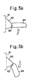
- Figs. 5a and 5b are each a schematic descriptive drawing of an electric retractable door mirror device provided in a motor vehicle.
- a mirror base 62 is firmly fixed to the body 61 of the vehicle.
- a mirror assembly 64 to be driven which includes a mirror (not shown), etc. is rotatably fixed to the mirror base 62 via a shaft 63.
- the mirror assembly 64 also includes a direct-current motor (not shown). By reversing the dc motor, the mirror assembly 64 is rotated on the shaft 63 from a dormant position (where the mirror assembly 64 is retracted) shown in Fig. 5b to an in-use position (where the mirror assembly 64 performs its normal function) shown in Fig. 5a. On the other hand, by running the dc motor in a normal direction, the mirror assembly 64 is rotated on the shaft 63 from the in-use position to the dormant position. When the mirror assembly 64 reaches the in-use position with the returning motion or when the mirror assembly 64 reaches the dormant position with the retracting motion, the mirror assembly 64 is regulated not to move more by means of a stopping member (not shown).
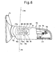
- Figs. 6 and 7 show an example of such an electric retractable door mirror device (see Japanese Utility Model Application Early Laid-Open Publication No. Hei 4-76196).
- reference numeral 71 designates a mirror base
- reference numeral 72 designates a shaft holder fastened to the mirror base 71
- reference numeral 73 designates a shaft extending from the shaft holder 72
- reference numeral 74 designates a mirror assembly.
- the mirror assembly 74 includes a mirror housing 75, a unit bracket 76 fastened to the mirror housing 75, a mirror 77, a power unit 78 and a tilting driving portion 79 by both of which the mirror 77 is tilted.
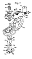
- the tilting driving portion 79 comprises a dc motor 51, a worm gear 80 fastened to an output shaft (not shown) of the dc motor 51, a worm wheel 81 which meshes with the worm gear 80, a worm shaft 82 an end of which is cut D-shaped and is fitted into a center hole 81a of the worm wheel 81 so as to move in its axial direction but not to turn, a worm wheel 83 which meshes with the worm shaft 82, a gear 84 disposed coaxially with the worm wheel 83 so as to turn simultaneously with the worm wheel 83, and an idle gear 85 which meshes with the gear 84.
- the shaft holder 72 has arc-shaped grooves 72a, 72a coaxial with the shaft 73 and each of which is engaged with a ball 86 buried in a bracket 76.
- the shaft holder 72 also has a projection 72b.
- the shaft 73 has chamfers 73a, 73a extending in the direction of the axis of the shaft 73 and an engagement groove 73b formed on the upper side of the chamfer 73a and extending in the circumferential direction of the shaft 73.
- To the shaft 73 are coaxially fitted washers 87, 88, a clutch holder 89, a clutch gear 90 which meshes with the idle gear 85, a compression spring 91, and a push nut 92 which is engaged with the engagement groove 73b.
- the clutch holder 89 has, on its upper surface, convex portions 89a which are fitted into corresponding concave portions (not shown) formed in the lower surface of the clutch gear 90. Usually, the convex and concave portions are in engagement with each other by the force of the compression spring 91.
- the clutch holder 89 has an engagement hole 89b which is engaged with the chamfers 73a.
- the alternate long and short dash line indicates a position where the mirror assembly 74 is retracted in a state of the end of the mirror assembly 74 being directed rearwards with respect to the vehicle body
- the alternate long and two short dashes line indicates a position where the mirror assembly 74 is retracted in a state of the end of the mirror assembly 74 being directed forwards with respect to the vehicle body.
- the clutch gear 90 and the clutch holder 89 are disengaged from each other against the force of the compression spring 91, so that the mirror assembly 74 is rotated in a direction in which a shock to the mirror assembly 74 is reduced. As a result, the mirror assembly 74 and the dc motor 51 are prevented from being damaged.
- such an electric retractable door mirror device has a control circuit for controlling the driving of the dc motor 51.
- the control circuit cuts off the electric supply to the dc motor 51 by electrically detecting the stopping of the mirror assemblies 64, 74 by various kinds of detecting means.
- the control circuit stops the driving of the dc motor 51 such that, when the mirror assembly 74 is driven and situated in a retracted position (dormant position) or in an in-use position, the control circuit cuts off the electric supply to the dc motor 51 by detecting the arrival of the mirror assembly 74 in the position by means of a positive temperature coefficient thermistor (PTC thermistor).
- PTC thermistor positive temperature coefficient thermistor
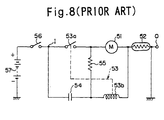
- reference character 53b designates a relay coil.
- a relay 53 is made up of the relay coil 53b and the relay contact 53a.
- Reference character 54 designates a condenser (capacitor) for actuating the dc motor 51
- reference character 55 designates a resistance for relay self-hold
- reference character 56 designates a remote control switch used as an operation switch for operating a thing (door mirror, power window, power seat, etc.) to be driven
- reference character 57 designates a battery source.
- the dc motor 51 is actuated by closing the remote control switch 56 in order to retract or protract the mirror assembly 74.
- a current passes through the battery source 57, the remote control switch 56, the condenser 54, the relay coil 53b, the PTC thermistor 52, and a vehicle body's ground, in order of mention.
- the relay coil 53b is excited.
- the relay contact 53a is closed and, as a result, the current from the battery source 57 passes through the relay contact 53a, the dc motor 51, the PTC thermistor 52, and the vehicle body's ground.
- a part of the current flowing from the relay contact 53a to the dc motor 51 branches off therefrom and passes through the resistance 55 for relay self-hold, the relay coil 53b, the PTC thermistor 52, and the vehicle body's ground. Accordingly, the relay coil 53b remains excited.
- the dc motor 51 continues to run in the normal or reverse direction and accordingly the mirror assembly 74 is retracted or protracted.
- the conventional control circuit mentioned above is arranged such that, through the PTC thermistor 52, the stopping of the mirror assembly 74 is detected and the switching operation is carried out.
- This arrangement has an advantage in that it is simpler than an arrangement in which a current detecting element, etc. carry out a switching operation, but has the following disadvantage.
- the flow of the overcurrent to the PTC thermistor 52 brings about the high resistance of the PTC thermistor 52, thereby bringing about the increase of voltage drop caused by the PTC thermistor 52.
- a current passing through the relay coil 53b decreases and accordingly the relay contact 53a is opened.
- a voltage between both ends of the condenser 54 varies from a voltage value between both ends of the resistance 55 obtained immediately after the relay contact 53a is opened to a voltage value of the source obtained immediately before the resistance of the PTC thermistor 52 returns to its initial state after the natural cooling of the PTC thermistor 52.
- a control circuit for controlling the driving of a direct-current motor comprises a DC electric power source (11); a DC motor (15) for driving a think to be driven, a power terminal of said DC motor (15) being connected to an electrode of said DC electric power source at least via a relay contact (14a) and a control switch (12), the other power terminal of said DC motor (15) being connected to the other electrode of said DC electric power source (11); a relay coil (14b) an end of which is connected to a point between said control switch (12) and said relay contact (14a) via a condenser (16) for startup and the other end is connected to the other power terminal of said DC motor (15), a relay (14) being made up of said relay coil (14b) and said relay contact (14a); a discharge resistance (18) for causing said condenser (16) for startup to discharge, said discharge resistance (18) being connected in parallel to said condenser (16) for startup, a resistance (17) for relay self-hold, and end of said resistance (17)
- an end of the positive temperature coefficient thermistor is connected to a point between the control switch and the condenser for startup, and the other end of the positive temperature coefficient thermistor is connected to the relay contact.
- an end of the positive temperature coefficient thermistor is connected to a point between the dc motor and the resistance for relay self-hold, and the other end of the thermistor is connected to the relay contact.
- the positive temperature coefficient thermistor is connected in parallel to the motor actuating condenser with respect to the dc electric power. Of all the circuit components, the motor actuating condenser undergoes an electrically greater change of state with the lapse of time as the positive temperature coefficient thermistor undergoes the same.
- the positive temperature coefficient thermistor does not take any electrical action at the very moment of the actuation of the dc motor and after the dc motor is stopped. For this reason, the optimum combinations of the circuit components including the motor actuating condenser can be easily determined. Additionally, chattering which occurs when the dc motor is operated to stop can be prevented. Further, the lag of the motor stopping action is prevented, the life of the relay contact is lengthened, and malfunction is prevented.
- the positive temperature coefficient thermistor may be disposed between the relay contact and a point between the control switch and the condenser for startup or may be disposed between the relay contact and a point between the dc motor and the resistance for relay self-hold. If so, restart is facilitated because the positive temperature coefficient thermistor does not exist in a current path leading to the relay coil when the control switch is operated (when the dc motor is actuated).
- Fig. 1 is a control circuit for controlling the driving of a dc motor, showing a first embodiment of the present invention.
- Fig. 2 is a control circuit for controlling the driving of a dc motor, showing a second embodiment of the present invention.
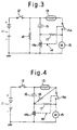
- Fig. 3 is a control circuit for controlling the driving of a dc motor, showing a third embodiment of the present invention.
- Fig. 4 is a control circuit for controlling the driving of a dc motor, showing a fourth embodiment of the present invention.
- Fig. 5a is a descriptive drawing of a motor-driven retractable door mirror device which is in an in-use position
- Fig. 5b is a descriptive drawing of the motor-driven retractable door mirror device which is in a retracted position.
- Fig. 6 is a plan view, partly in section, of the motor-driven retractable door mirror device.
- Fig. 7 is an exploded view of a main part of the motor-driven retractable door mirror device, showing its internal structure.
- Fig. 8 shows a conventional control circuit for controlling the driving of a dc motor.
- Fig. 1 shows a control circuit for controlling the driving of a direct-current motor according to a first embodiment of the present invention.
- reference numeral 11 designates a battery power source (direct-current power source).
- a positive electrode (+) of the battery power source 11 is connected to a power terminal of a direct-current motor (dc motor) 15, by which devices to be driven, such as a door mirror, power seat, etc., are driven, via a remote control switch 12 used as a operating switch for operating the motor-driven devices, a PTC thermistor (positive temperature coefficient thermistor) 13, and a relay contact 14a.
- a negative electrode (-) of the battery power source 11 and the other power terminal of the dc motor 15 are individually connected to a vehicle body's ground.
- a relay 14 is made up of the relay contact 14a and a relay coil 14b. An end of the relay coil 14b is connected through a condenser 16 for startup to a point where the remote control switch 12 and the PTC thermistor 13 are connected to each other. The other end of the relay coil 14b is connected to the other power terminal of the dc motor 15.
- Reference numeral 17 designates a resistance for relay self-hold. An end of the resistance 17 is connected to a point between the relay contact 14a and the dc motor 15, and the other end of the resistance 17 is connected to a point between the condenser 16 and the relay coil 14b.
- Reference numeral 18 designates a resistance for discharging electricity from the condenser 16. The resistance 18 is connected to the condenser 16 in parallel.
- a device (not shown) to be driven by the dc motor is a mirror assembly as in the case described with reference to Fig. 8.
- the PTC thermistor 13 stops the dc motor 15 in the following way.
- the mirror assembly driven by the dc motor 15 reaches a retracted position (this case is shown in Fig.1) or in-use position (where the mirror assembly performs its normal function) and is physically stopped by a stopping member (not shown).
- the temperature of the PTC thermistor 13 is raised by an excess current generated when the dc motor 15 reaches an overloaded state. Thereby, the PTC thermistor 13 heightens its own resistance, thereby lessening a current passing through the relay coil 14b which is performing self-hold. As a result, the relay contact 14a is opened to stop the dc motor 15.
- the relay contact 14a is closed, and a current from the battery power source 11 passes through the PTC thermistor 13, the relay contact 14a, the dc motor 15, and the vehicle body's ground. As a result, the dc motor is actuated. At this time, in a current path leading to the dc motor 15, a part of the current going from the relay contact 14a to the dc motor 15 branches off from the path and flows from the relay contact 14a to the vehicle body's ground through the resistance 17 and the relay coil 14b. The relay coil 14b is kept excited. Accordingly, the dc motor 15 remains running in a normal or reverse direction (in this case, the dc motor 15 runs in the normal direction), and the mirror assembly is retracted or protracted (in this case, the mirror assembly is retracted).
- the current passing through the dc motor 15 reaches a state of an excess current. Since the PTC thermistor 13 is disposed in the current path leading to the dc motor 15, the excess current mentioned above also passes through the PTC thermistor 13. For this reason, the PTC thermistor 13 is heated and becomes high in resistance and, as a result, lessens the current passing therethrough. Accordingly, the current flowing to the relay coil 14b through the resistance 17 is also lessened, and the relay contact 14a is opened to cut off the current flowing to the dc motor 15.
- the PTC thermistor 13 is connected in parallel (not in series) to the condenser 16 which, like the PTC thermistor 13, electrically suffers a great change of state with the lapse of time among all the components of the control circuit. Accordingly, since the PTC thermistor 13 does not electrically perform any function at the very moment when the dc motor 15 is actuated and after the dc motor 15 is stopped, the optimum combination of the circuit components including the condenser 16 can be easily determined. Thereby, the occurrence of chattering is prevented when the dc motor 15 is operated to stop, and the lag of the stopping action of the dc motor is prevented. Further, the service life of the relay contact 14a is lengthened, and malfunction is prevented.
- the restart of the dc motor 15 is facilitated because, as shown in Fig. 1, the PTC thermistor 13 is disposed between a point via which the remote control switch 12 is connected to the condenser 16 and the relay contact 14a, in other words, the PTC thermistor 13 does not exist in a current path through which a current flows to the relay coil 14b when the remote control switch 12 is switched on (i.e., when the dc motor 15 is actuated).
- Fig. 2 shows a second embodiment of the present invention.
- the same numerals are given to the same components or equivalents as in the first embodiment, respectively.
- a relay contact 14a comprises a movable contact 14a1 connected to the dc motor 15, a normally-closed fixed contact NC with which the movable contact 14a1 is brought into contact when the relay coil 14b is not excited, and a normally-opened fixed contact NO with which the movable contact 14a1 is brought into contact when the relay coil 14b is excited.
- a PTC thermistor 13 is disposed between the fixed contact NO and a point via which a remote control switch 12 is connected to a condenser 16 for startup.
- a resistance 18 for discharging electricity from the condenser 16 is disposed between the fixed contact NC and the point via which the switch 12 is connected to the condenser 16. Except for this arrangement, the construction of the circuit is the same as in the first embodiment. In the second embodiment, the resistance 18 is inserted only when the relay coil 14b is not excited. The resistance 17 is also used in common as a resistance for discharging electricity from the condenser 16.
- the circuit arranged when the relay 14 is working (when the relay coil 14b is not excited) is simpler than that in the first embodiment. Accordingly, parameters, characteristics, etc. of the respective components of the circuit can be easily determined, and a late response occurring when the dc motor 15 is operated to stop can be prevented.
- Fig. 3 shows a third embodiment of the present invention.
- the same numerals are given to the same components or equivalents as in the first embodiment, respectively.
- a resistance 18 for discharging electricity from a condenser 16 for startup is connected in parallel to a connection consisting of the condenser 16 and a relay coil 14b. Except for this arrangement, the control circuit is constructed in the same way as in the first embodiment.
- the resistance 18 is always connected in parallel to the condenser 16 via the relay coil 14b regardless of whether a relay 14 works or not (whether the relay coil 14b is excited or not).
- the discharge from the condenser 16 in the circuit shown in Fig. 2 is carried out when the relay coil 14b is not excited (i.e., when the relay 14 does not work) and, for this duration, a resistance 17 for relay self-hold besides the resistance 18 is included in the charging circuit. Accordingly, the determination of parameters, characteristics, etc., of these resistances becomes relatively difficult, and a time constant thereof becomes larger.
- the resistance of the relay coil 14b is negligibly small when the relay coil 14b is not excited (when the relay 14 does not work). It might be allowable to say that only the resistance 18 is connected in parallel to the condenser 16. Accordingly, the determination of the parameters, characteristics, etc. can be easily made, and the time constant can be made small. As a result, the discharge from the condenser 16 is carried out quickly and certainly.
- Fig. 4 shows a fourth embodiment of the present invention.
- the same numerals are given to the same components or equivalents as in the first embodiment, respectively.
- a resistance 18 for discharging electricity from a condenser 16 for startup is disposed between a point via which a PTC thermistor 13 is connected to a relay contact 14a and a point via which the condenser 16 is connected to a relay coil 14b.
- the control circuit is constructed in the same way as in the first embodiment shown in Fig. 1.
- the resistance 18 is always connected in parallel to the condenser 16 via the PTC thermistor 13 regardless of whether a relay 14 works or not (whether the relay coil 14b is excited or not).
- the resistance of the PTC thermistor 13 is negligibly small when the relay coil 14b is not excited (when the relay 14 does not work). It might be allowable to say that only the resistance 18 is connected in parallel to the condenser 16. Accordingly, the determination of the parameters, characteristics, etc. can be easily made, and the time constant can be made small. As a result, the discharge from the condenser 16 is carried out quickly and certainly.
- the present invention is applied to a control circuit for controlling the driving of a direct-current motor used to drive a motor-driven retractable door mirror device.
- the present invention is applicable to, in a broad sense, a motor controlling technique in which a dc motor is stopped when a device to be driven by the dc motor is brought into contact with a stopping member.
- chattering which occurs when a dc motor is operated to stop is prevented, the lag in the stop of the motor is prevented, the life of a relay contact is lengthened, operational malfunction is prevented, and restart is facilitated.
Landscapes
- Engineering & Computer Science (AREA)
- Multimedia (AREA)
- Mechanical Engineering (AREA)
- Power Engineering (AREA)
- Stopping Of Electric Motors (AREA)
- Control Of Direct Current Motors (AREA)
- Rear-View Mirror Devices That Are Mounted On The Exterior Of The Vehicle (AREA)
- Motor And Converter Starters (AREA)
- Protection Of Generators And Motors (AREA)
Applications Claiming Priority (3)
| Application Number | Priority Date | Filing Date | Title |
|---|---|---|---|
| JP07175895A JP3237446B2 (ja) | 1995-03-29 | 1995-03-29 | 直流モータ駆動制御回路 |
| JP71758/95 | 1995-03-29 | ||
| JP7175895 | 1995-03-29 |
Publications (3)
| Publication Number | Publication Date |
|---|---|
| EP0735666A2 EP0735666A2 (en) | 1996-10-02 |
| EP0735666A3 EP0735666A3 (en) | 1997-05-28 |
| EP0735666B1 true EP0735666B1 (en) | 1999-09-29 |
Family
ID=13469769
Family Applications (1)
| Application Number | Title | Priority Date | Filing Date |
|---|---|---|---|
| EP96105085A Expired - Lifetime EP0735666B1 (en) | 1995-03-29 | 1996-03-29 | Control circuit for controlling the driving of a dc motor |
Country Status (5)
| Country | Link |
|---|---|
| US (1) | US5793171A (ko) |
| EP (1) | EP0735666B1 (ko) |
| JP (1) | JP3237446B2 (ko) |
| KR (1) | KR100216416B1 (ko) |
| DE (1) | DE69604435T2 (ko) |
Families Citing this family (18)
| Publication number | Priority date | Publication date | Assignee | Title |
|---|---|---|---|---|
| US5864458A (en) * | 1995-09-14 | 1999-01-26 | Raychem Corporation | Overcurrent protection circuits comprising combinations of PTC devices and switches |
| DE19753852A1 (de) * | 1997-12-04 | 1999-06-17 | Siemens Ag | Elektromagnetisches Relais |
| US6166350A (en) * | 1999-08-13 | 2000-12-26 | Illinois Tool Works Inc. | Wire feed apparatus and method with nonlinear stage |
| US6204479B1 (en) | 1999-08-13 | 2001-03-20 | Illinois Tool Works Inc. | Thermistor protection for a wire feed motor |
| JP3581838B2 (ja) * | 2001-05-25 | 2004-10-27 | 株式会社村上開明堂 | 電動格納式ドアミラーの制御方式 |
| NL1021382C2 (nl) * | 2002-09-03 | 2004-03-05 | Iku Holding Montfoort Bv | Electromotorschakeling met beveiliging tegen overbelasting. |
| AU2003901355A0 (en) * | 2003-03-25 | 2003-04-10 | Schefenacker Vision Systems Australia Pty Ltd | Power fold mirror control circuit |
| US6998803B2 (en) * | 2003-04-16 | 2006-02-14 | Therm-O-Disc, Incorporated | Enhanced performance for DC motor drive switching |
| JP4193785B2 (ja) | 2003-11-19 | 2008-12-10 | 市光工業株式会社 | 車両用電動格納装置の車両への取付方法及びこれに用いる車両用電動格納装置及びこの車両用電動格納装置が取り付けられた車両 |
| JP4292983B2 (ja) | 2003-12-24 | 2009-07-08 | 市光工業株式会社 | モータ駆動装置及び電動格納式ドアミラー |
| FR2875073B1 (fr) * | 2004-09-03 | 2008-08-08 | Faurecia Sieges Automobile | Circuit de commande de moteur electrique pour organe de liaison de siege de vehicule automobile, procede de commande de tels moteurs, systemes comprenant un tel systeme de commande et un siege de vehicule, et vehicule |
| KR100748524B1 (ko) * | 2005-04-22 | 2007-08-13 | 엘지전자 주식회사 | 공기조화기의 팬모터 구동장치 |
| KR100756489B1 (ko) | 2006-01-03 | 2007-09-07 | 엘지전자 주식회사 | 자기자화모터 구동회로 |
| KR101198234B1 (ko) * | 2006-05-02 | 2012-11-07 | 엘지전자 주식회사 | 모터의 기동 제어 장치 |
| CN101976638B (zh) * | 2010-11-05 | 2012-10-24 | 山东思科电气有限公司 | 单极无弧永磁交流接触器 |
| CN102355089A (zh) * | 2011-09-30 | 2012-02-15 | 田乃信 | 一种自动识别的电机开关 |
| KR102410936B1 (ko) * | 2017-04-04 | 2022-06-20 | 현대자동차주식회사 | 차량 모터 제어 장치 및 방법 |
| CN114930485A (zh) * | 2019-12-05 | 2022-08-19 | 苏州力特奥维斯保险丝有限公司 | 具有反向连接保护的继电器组件 |
Family Cites Families (10)
| Publication number | Priority date | Publication date | Assignee | Title |
|---|---|---|---|---|
| US3803866A (en) * | 1972-10-30 | 1974-04-16 | Carrier Corp | Start winding protection device |
| US3965392A (en) * | 1974-01-02 | 1976-06-22 | Sprague Electric Company | Motor start system with two dissimilar PTCR elements |
| US4037316A (en) * | 1974-09-23 | 1977-07-26 | General Electric Company | Method of assembling temperature responsive resistance member |
| US4066937A (en) * | 1976-01-13 | 1978-01-03 | Lennox Industries, Inc. | Control circuit for a two speed single phase motor |
| US4161681A (en) * | 1977-03-17 | 1979-07-17 | General Electric Company | Prime mover, method of operating such and circuit |
| FR2579033B1 (fr) * | 1985-03-15 | 1987-04-10 | Etri Sa | Moteur electrique comportant un dispositif de protection a thermistances contre les surintensites |
| US5053908A (en) * | 1989-11-29 | 1991-10-01 | Texas Instruments Incorporated | Psc motor start system |
| JPH0476196A (ja) * | 1990-07-17 | 1992-03-10 | Kyokuto Kaihatsu Kogyo Co Ltd | 配管推進作業における排土方法 |
| JPH0530767A (ja) * | 1991-07-17 | 1993-02-05 | Asmo Co Ltd | 自動停止制御装置 |
| US5502609A (en) * | 1994-12-08 | 1996-03-26 | General Electric Company | Electric circuitry for preventing contactor tip contamination in dry switching applications |
-
1995
- 1995-03-29 JP JP07175895A patent/JP3237446B2/ja not_active Expired - Lifetime
-
1996
- 1996-03-27 KR KR1019960008512A patent/KR100216416B1/ko not_active IP Right Cessation
- 1996-03-29 US US08/623,692 patent/US5793171A/en not_active Expired - Lifetime
- 1996-03-29 DE DE69604435T patent/DE69604435T2/de not_active Expired - Lifetime
- 1996-03-29 EP EP96105085A patent/EP0735666B1/en not_active Expired - Lifetime
Also Published As
| Publication number | Publication date |
|---|---|
| JPH08275567A (ja) | 1996-10-18 |
| EP0735666A2 (en) | 1996-10-02 |
| KR100216416B1 (ko) | 1999-08-16 |
| DE69604435D1 (de) | 1999-11-04 |
| DE69604435T2 (de) | 2000-03-09 |
| JP3237446B2 (ja) | 2001-12-10 |
| EP0735666A3 (en) | 1997-05-28 |
| KR960036284A (ko) | 1996-10-28 |
| US5793171A (en) | 1998-08-11 |
Similar Documents
| Publication | Publication Date | Title |
|---|---|---|
| EP0735666B1 (en) | Control circuit for controlling the driving of a dc motor | |
| US5264766A (en) | Wiper motor high current protection PTC | |
| US6252363B1 (en) | Circuit for timed position control of device driven by a DC motor | |
| JP3043961B2 (ja) | 電動格納式ドアミラーの制御装置 | |
| US6002224A (en) | One touch vehicle window operating circuit | |
| JP2557691Y2 (ja) | 駆動装置におけるスイッチ回路 | |
| KR200161289Y1 (ko) | 자동차용 전동접이식 백미러 제어장치 | |
| JP2564738Y2 (ja) | 駆動装置におけるスイッチ回路 | |
| JP2000211429A (ja) | モ―タ駆動制御回路 | |
| JPH11122961A (ja) | モータ駆動制御回路 | |
| JP2557690Y2 (ja) | 駆動装置におけるスイッチ回路 | |
| JPH11206164A (ja) | モータ駆動制御回路 | |
| JPH0417388Y2 (ko) | ||
| JP3380035B2 (ja) | 自動車用電動格納ドアミラーの駆動回路 | |
| JP2001287592A (ja) | 電動格納式ドアミラーの制御回路 | |
| JP2557689Y2 (ja) | 駆動装置におけるスイッチ回路 | |
| KR19980063525U (ko) | 자동차용 전동접이식 백미러 구동장치 | |
| JP2002027769A (ja) | 電動格納ドアミラーモジュール | |
| JPH0419056B2 (ko) | ||
| JP2821170B2 (ja) | 電動車輛の制御装置 | |
| JP2000224758A (ja) | モータ駆動制御回路 | |
| JPS5811877Y2 (ja) | シヤリヨウヨウドアノセジヨウソウチ | |
| JPH0347438Y2 (ko) | ||
| JPH053566U (ja) | パワーウインドレギユレータの制御装置 | |
| JPH0515695U (ja) | 駆動装置におけるスイツチ回路 |
Legal Events
| Date | Code | Title | Description |
|---|---|---|---|
| PUAI | Public reference made under article 153(3) epc to a published international application that has entered the european phase |
Free format text: ORIGINAL CODE: 0009012 |
|
| 17P | Request for examination filed |
Effective date: 19960329 |
|
| AK | Designated contracting states |
Kind code of ref document: A2 Designated state(s): DE FR GB |
|
| PUAL | Search report despatched |
Free format text: ORIGINAL CODE: 0009013 |
|
| AK | Designated contracting states |
Kind code of ref document: A3 Designated state(s): DE FR GB |
|
| 17Q | First examination report despatched |
Effective date: 19980529 |
|
| GRAG | Despatch of communication of intention to grant |
Free format text: ORIGINAL CODE: EPIDOS AGRA |
|
| GRAG | Despatch of communication of intention to grant |
Free format text: ORIGINAL CODE: EPIDOS AGRA |
|
| GRAH | Despatch of communication of intention to grant a patent |
Free format text: ORIGINAL CODE: EPIDOS IGRA |
|
| GRAH | Despatch of communication of intention to grant a patent |
Free format text: ORIGINAL CODE: EPIDOS IGRA |
|
| GRAA | (expected) grant |
Free format text: ORIGINAL CODE: 0009210 |
|
| AK | Designated contracting states |
Kind code of ref document: B1 Designated state(s): DE FR GB |
|
| REF | Corresponds to: |
Ref document number: 69604435 Country of ref document: DE Date of ref document: 19991104 |
|
| ET | Fr: translation filed | ||
| PLBE | No opposition filed within time limit |
Free format text: ORIGINAL CODE: 0009261 |
|
| STAA | Information on the status of an ep patent application or granted ep patent |
Free format text: STATUS: NO OPPOSITION FILED WITHIN TIME LIMIT |
|
| 26N | No opposition filed | ||
| REG | Reference to a national code |
Ref country code: GB Ref legal event code: IF02 |
|
| PGFP | Annual fee paid to national office [announced via postgrant information from national office to epo] |
Ref country code: FR Payment date: 20110317 Year of fee payment: 16 |
|
| PGFP | Annual fee paid to national office [announced via postgrant information from national office to epo] |
Ref country code: DE Payment date: 20110323 Year of fee payment: 16 Ref country code: GB Payment date: 20110323 Year of fee payment: 16 |
|
| GBPC | Gb: european patent ceased through non-payment of renewal fee |
Effective date: 20120329 |
|
| REG | Reference to a national code |
Ref country code: FR Ref legal event code: ST Effective date: 20121130 |
|
| PG25 | Lapsed in a contracting state [announced via postgrant information from national office to epo] |
Ref country code: FR Free format text: LAPSE BECAUSE OF NON-PAYMENT OF DUE FEES Effective date: 20120402 Ref country code: GB Free format text: LAPSE BECAUSE OF NON-PAYMENT OF DUE FEES Effective date: 20120329 |
|
| REG | Reference to a national code |
Ref country code: DE Ref legal event code: R119 Ref document number: 69604435 Country of ref document: DE Effective date: 20121002 |
|
| PG25 | Lapsed in a contracting state [announced via postgrant information from national office to epo] |
Ref country code: DE Free format text: LAPSE BECAUSE OF NON-PAYMENT OF DUE FEES Effective date: 20121002 |