EP0725559A2 - Verfahren und Vorrichtung zum Aufbringen eines Films auf eine Oberfläche - Google Patents
Verfahren und Vorrichtung zum Aufbringen eines Films auf eine Oberfläche Download PDFInfo
- Publication number
- EP0725559A2 EP0725559A2 EP96101082A EP96101082A EP0725559A2 EP 0725559 A2 EP0725559 A2 EP 0725559A2 EP 96101082 A EP96101082 A EP 96101082A EP 96101082 A EP96101082 A EP 96101082A EP 0725559 A2 EP0725559 A2 EP 0725559A2
- Authority
- EP
- European Patent Office
- Prior art keywords
- film
- roll
- laminated film
- adhesive tape
- presser roll
- Prior art date
- Legal status (The legal status is an assumption and is not a legal conclusion. Google has not performed a legal analysis and makes no representation as to the accuracy of the status listed.)
- Granted
Links
Images


Classifications
-
- B—PERFORMING OPERATIONS; TRANSPORTING
- B32—LAYERED PRODUCTS
- B32B—LAYERED PRODUCTS, i.e. PRODUCTS BUILT-UP OF STRATA OF FLAT OR NON-FLAT, e.g. CELLULAR OR HONEYCOMB, FORM
- B32B37/00—Methods or apparatus for laminating, e.g. by curing or by ultrasonic bonding
- B32B37/10—Methods or apparatus for laminating, e.g. by curing or by ultrasonic bonding characterised by the pressing technique, e.g. using action of vacuum or fluid pressure
- B32B37/1045—Intermittent pressing, e.g. by oscillating or reciprocating motion of the pressing means
-
- B—PERFORMING OPERATIONS; TRANSPORTING
- B29—WORKING OF PLASTICS; WORKING OF SUBSTANCES IN A PLASTIC STATE IN GENERAL
- B29C—SHAPING OR JOINING OF PLASTICS; SHAPING OF MATERIAL IN A PLASTIC STATE, NOT OTHERWISE PROVIDED FOR; AFTER-TREATMENT OF THE SHAPED PRODUCTS, e.g. REPAIRING
- B29C63/00—Lining or sheathing, i.e. applying preformed layers or sheathings of plastics; Apparatus therefor
- B29C63/0004—Component parts, details or accessories; Auxiliary operations
- B29C63/0013—Removing old coatings
-
- B—PERFORMING OPERATIONS; TRANSPORTING
- B32—LAYERED PRODUCTS
- B32B—LAYERED PRODUCTS, i.e. PRODUCTS BUILT-UP OF STRATA OF FLAT OR NON-FLAT, e.g. CELLULAR OR HONEYCOMB, FORM
- B32B38/00—Ancillary operations in connection with laminating processes
- B32B38/0004—Cutting, tearing or severing, e.g. bursting; Cutter details
-
- B—PERFORMING OPERATIONS; TRANSPORTING
- B32—LAYERED PRODUCTS
- B32B—LAYERED PRODUCTS, i.e. PRODUCTS BUILT-UP OF STRATA OF FLAT OR NON-FLAT, e.g. CELLULAR OR HONEYCOMB, FORM
- B32B38/00—Ancillary operations in connection with laminating processes
- B32B38/18—Handling of layers or the laminate
- B32B38/1825—Handling of layers or the laminate characterised by the control or constructional features of devices for tensioning, stretching or registration
- B32B38/1833—Positioning, e.g. registration or centering
-
- B—PERFORMING OPERATIONS; TRANSPORTING
- B32—LAYERED PRODUCTS
- B32B—LAYERED PRODUCTS, i.e. PRODUCTS BUILT-UP OF STRATA OF FLAT OR NON-FLAT, e.g. CELLULAR OR HONEYCOMB, FORM
- B32B38/00—Ancillary operations in connection with laminating processes
- B32B38/18—Handling of layers or the laminate
- B32B38/1858—Handling of layers or the laminate using vacuum
-
- G—PHYSICS
- G03—PHOTOGRAPHY; CINEMATOGRAPHY; ANALOGOUS TECHNIQUES USING WAVES OTHER THAN OPTICAL WAVES; ELECTROGRAPHY; HOLOGRAPHY
- G03F—PHOTOMECHANICAL PRODUCTION OF TEXTURED OR PATTERNED SURFACES, e.g. FOR PRINTING, FOR PROCESSING OF SEMICONDUCTOR DEVICES; MATERIALS THEREFOR; ORIGINALS THEREFOR; APPARATUS SPECIALLY ADAPTED THEREFOR
- G03F7/00—Photomechanical, e.g. photolithographic, production of textured or patterned surfaces, e.g. printing surfaces; Materials therefor, e.g. comprising photoresists; Apparatus specially adapted therefor
- G03F7/16—Coating processes; Apparatus therefor
-
- B—PERFORMING OPERATIONS; TRANSPORTING
- B32—LAYERED PRODUCTS
- B32B—LAYERED PRODUCTS, i.e. PRODUCTS BUILT-UP OF STRATA OF FLAT OR NON-FLAT, e.g. CELLULAR OR HONEYCOMB, FORM
- B32B2457/00—Electrical equipment
-
- B—PERFORMING OPERATIONS; TRANSPORTING
- B32—LAYERED PRODUCTS
- B32B—LAYERED PRODUCTS, i.e. PRODUCTS BUILT-UP OF STRATA OF FLAT OR NON-FLAT, e.g. CELLULAR OR HONEYCOMB, FORM
- B32B2457/00—Electrical equipment
- B32B2457/08—PCBs, i.e. printed circuit boards
-
- Y—GENERAL TAGGING OF NEW TECHNOLOGICAL DEVELOPMENTS; GENERAL TAGGING OF CROSS-SECTIONAL TECHNOLOGIES SPANNING OVER SEVERAL SECTIONS OF THE IPC; TECHNICAL SUBJECTS COVERED BY FORMER USPC CROSS-REFERENCE ART COLLECTIONS [XRACs] AND DIGESTS
- Y10—TECHNICAL SUBJECTS COVERED BY FORMER USPC
- Y10T—TECHNICAL SUBJECTS COVERED BY FORMER US CLASSIFICATION
- Y10T156/00—Adhesive bonding and miscellaneous chemical manufacture
- Y10T156/12—Surface bonding means and/or assembly means with cutting, punching, piercing, severing or tearing
- Y10T156/1317—Means feeding plural workpieces to be joined
- Y10T156/1322—Severing before bonding or assembling of parts
- Y10T156/133—Delivering cut part to indefinite or running length web
-
- Y—GENERAL TAGGING OF NEW TECHNOLOGICAL DEVELOPMENTS; GENERAL TAGGING OF CROSS-SECTIONAL TECHNOLOGIES SPANNING OVER SEVERAL SECTIONS OF THE IPC; TECHNICAL SUBJECTS COVERED BY FORMER USPC CROSS-REFERENCE ART COLLECTIONS [XRACs] AND DIGESTS
- Y10—TECHNICAL SUBJECTS COVERED BY FORMER USPC
- Y10T—TECHNICAL SUBJECTS COVERED BY FORMER US CLASSIFICATION
- Y10T156/00—Adhesive bonding and miscellaneous chemical manufacture
- Y10T156/12—Surface bonding means and/or assembly means with cutting, punching, piercing, severing or tearing
- Y10T156/1317—Means feeding plural workpieces to be joined
- Y10T156/1322—Severing before bonding or assembling of parts
- Y10T156/1339—Delivering cut part in sequence to serially conveyed articles
-
- Y—GENERAL TAGGING OF NEW TECHNOLOGICAL DEVELOPMENTS; GENERAL TAGGING OF CROSS-SECTIONAL TECHNOLOGIES SPANNING OVER SEVERAL SECTIONS OF THE IPC; TECHNICAL SUBJECTS COVERED BY FORMER USPC CROSS-REFERENCE ART COLLECTIONS [XRACs] AND DIGESTS
- Y10—TECHNICAL SUBJECTS COVERED BY FORMER USPC
- Y10T—TECHNICAL SUBJECTS COVERED BY FORMER US CLASSIFICATION
- Y10T156/00—Adhesive bonding and miscellaneous chemical manufacture
- Y10T156/12—Surface bonding means and/or assembly means with cutting, punching, piercing, severing or tearing
- Y10T156/1317—Means feeding plural workpieces to be joined
- Y10T156/1343—Cutting indefinite length web after assembly with discrete article
-
- Y—GENERAL TAGGING OF NEW TECHNOLOGICAL DEVELOPMENTS; GENERAL TAGGING OF CROSS-SECTIONAL TECHNOLOGIES SPANNING OVER SEVERAL SECTIONS OF THE IPC; TECHNICAL SUBJECTS COVERED BY FORMER USPC CROSS-REFERENCE ART COLLECTIONS [XRACs] AND DIGESTS
- Y10—TECHNICAL SUBJECTS COVERED BY FORMER USPC
- Y10T—TECHNICAL SUBJECTS COVERED BY FORMER US CLASSIFICATION
- Y10T156/00—Adhesive bonding and miscellaneous chemical manufacture
- Y10T156/17—Surface bonding means and/or assemblymeans with work feeding or handling means
- Y10T156/1702—For plural parts or plural areas of single part
- Y10T156/1712—Indefinite or running length work
- Y10T156/1734—Means bringing articles into association with web
-
- Y—GENERAL TAGGING OF NEW TECHNOLOGICAL DEVELOPMENTS; GENERAL TAGGING OF CROSS-SECTIONAL TECHNOLOGIES SPANNING OVER SEVERAL SECTIONS OF THE IPC; TECHNICAL SUBJECTS COVERED BY FORMER USPC CROSS-REFERENCE ART COLLECTIONS [XRACs] AND DIGESTS
- Y10—TECHNICAL SUBJECTS COVERED BY FORMER USPC
- Y10T—TECHNICAL SUBJECTS COVERED BY FORMER US CLASSIFICATION
- Y10T156/00—Adhesive bonding and miscellaneous chemical manufacture
- Y10T156/17—Surface bonding means and/or assemblymeans with work feeding or handling means
- Y10T156/1702—For plural parts or plural areas of single part
- Y10T156/1712—Indefinite or running length work
- Y10T156/1741—Progressive continuous bonding press [e.g., roll couples]
-
- Y—GENERAL TAGGING OF NEW TECHNOLOGICAL DEVELOPMENTS; GENERAL TAGGING OF CROSS-SECTIONAL TECHNOLOGIES SPANNING OVER SEVERAL SECTIONS OF THE IPC; TECHNICAL SUBJECTS COVERED BY FORMER USPC CROSS-REFERENCE ART COLLECTIONS [XRACs] AND DIGESTS
- Y10—TECHNICAL SUBJECTS COVERED BY FORMER USPC
- Y10T—TECHNICAL SUBJECTS COVERED BY FORMER US CLASSIFICATION
- Y10T156/00—Adhesive bonding and miscellaneous chemical manufacture
- Y10T156/17—Surface bonding means and/or assemblymeans with work feeding or handling means
- Y10T156/1702—For plural parts or plural areas of single part
- Y10T156/1744—Means bringing discrete articles into assembled relationship
- Y10T156/1768—Means simultaneously conveying plural articles from a single source and serially presenting them to an assembly station
-
- Y—GENERAL TAGGING OF NEW TECHNOLOGICAL DEVELOPMENTS; GENERAL TAGGING OF CROSS-SECTIONAL TECHNOLOGIES SPANNING OVER SEVERAL SECTIONS OF THE IPC; TECHNICAL SUBJECTS COVERED BY FORMER USPC CROSS-REFERENCE ART COLLECTIONS [XRACs] AND DIGESTS
- Y10—TECHNICAL SUBJECTS COVERED BY FORMER USPC
- Y10T—TECHNICAL SUBJECTS COVERED BY FORMER US CLASSIFICATION
- Y10T156/00—Adhesive bonding and miscellaneous chemical manufacture
- Y10T156/19—Delaminating means
- Y10T156/1906—Delaminating means responsive to feed or shape at delamination
Definitions
- This invention relates to a method and apparatus for applying a film to the surface of a base plate for a printed circuit board, for example.
- a process for the manufacture of printed circuit boards used for electronic equipment such as computers includes a step of applying a laminated film to the surface of a base plate for the printed circuit board.
- a film applying apparatus used for applying the laminated film is constructed such that a continuous film wound on a film supply roll is guided via guide rolls to a leading end of a base plate while being conveyed by a conveying means, then tacked by a tacking member to the leading end of the base plate, and thereafter applied to the base plate under pressure by a lamination roll while conveyance of the base plate is further continued.
- a photosensitive layer laminating apparatus which includes a mechanism for separating, by means of an adhesive tape, a protective film (cover film) from the leading end of a film having an photosensitive layer covered with the protective film, a pair of opposed thermocompression laminating rolls for advancing the film having the photosensitive layer and a base plate while gripping and thereby bonding them with pressure and heat, and a mechanism for cutting the protective film and the photosensitive layer on the film.
- the laminating apparatus further includes an adhesive tape roll drivable by the protective film separating mechanism to achieve a take-up operation, a retractable presser bar for forcing the adhesive tape against a leading end of the protective film, a dancer roll for adjusting the length of a path of the adhesive tape, an a protective-film recovery roll for taking up the adhesive tape through a surface friction drive by a delivery roll for the film having the protective film.
- the presser bar has a front edge shaped to form an acute angle and forces the adhesive tape to a leading end of the protective film during which time it pulls the adhesive tape to stretch a length of the adhesive film stored by the dancer roll.
- the mechanism for cutting the protective film and the photosensitive layer on the film includes a round cutter (disk cutter) adapted to be forced against the protective film and movable in the widthwise direction of the film.
- the adhesive tape is normally set at two positions spaced in the widthwise direction of the film.
- the presser bar is pivotally movable within a fixed angular range and moved back and forth by an air cylinder.
- the air cylinder is provided by way of a pair of air cylinders disposed in tandem relation in the widthwise direction of the film and driven in synchronism with each other.
- the presser bar is reciprocated by the two laterally spaced synchronously driven air cylinders. Accordingly, if an adjustment due for establishing a uniform distribution of contact force throughout the width of the presser bar is difficult to achieve, the prior apparatus encounters a problem that due to irregular distribution of the contact force, one of the adhesive tapes bonded to the protective film fails to peel off or separate the protective film.
- the cutting mechanism including the round cutter forces the round cutter against the film to partly cut the thickness of the film while the film is held on a cutter backup plate.
- the round cutter is likely to be nicked or otherwise damaged due to an impact force exerted thereon when the round cutter impinges on a corner edge of the cutter backup plate as it runs onto the cutter backup plate. A frequent replacement of the round cutter is needed, accordingly.
- the tacking member has & heater disposed at a leading end of the tacking member for heating a leading end of the film to tack the film to the leading end of the base plate. Thereafter, the film is bonded to the base plate under pressure by lamination rolls while the base plate is continuously conveyed.
- the tacking member having completed tacking of the film to the leading end of the base plate moves in a direction away from the base plate, and a negative pressure or vacuum for attracting the film is ceased whereupon a tension roll disposed upstream of the tacking member is pulled by a spring in a direction to stretch a portion of the film located near the base plate.
- the protective film adhering to the adhesive tapes on the presser bar hinders backward movement of the film having the photosensitive layer with the result that a slack on the film created immediately after the tacking cannot be reduced.
- the slack film is pressure-bonded to the base plate by the lamination rolls, the bonded film involves generation of wrinkles or bubbles are trapped between the film and the base plate.
- heat generated from the heater at the leading end of the tacking member is transmitted to a main vacuum plate thereof, thereby heating the film even when a heat insulating material is disposed between the main vacuum plate and the leading end of the tacking member.
- the laminated film is heated up to a high temperature.
- the light-transmissible support film layer is thin and has a thickness not greater than 50 ⁇ m, certain problems would occur as described below.
- the photosensitive resin layer is influenced by heat while the film is held in contact with the front face of the tacking member during the film supplying and tacking operation.
- the film is held out of contact with the front face of the tacking member with the result that the photosensitive resin layer is not influenced by heat from the heater.
- a wiring pattern formed on the base plate after exposure and development processes may contain a defect.
- the laminated film becomes soft at a high temperature, these parts of the laminated film, which are located in front of the suction holes and suction grooves in the main vacuum plate, are bent or flexed by the action of a vacuum or suction and form recessed portions arranged in the same pattern as the suction holes and suction grooves. As a result of formation of the recessed portions, the photosensitive resin layer is not uniform in thickness.
- a wiring pattern formed on the base plate after the exposure and development processes includes a defect, ouch as an intrusion, a mouse nip or a break.
- the cover film since the cover film (protective film) is separated at a position downstream of the main vacuum plate (between the tacking member and the base plate), the photosensitive resin layer is rendered instable in viscosity by the effect of heat applied thereto.
- another problem caused from the instable viscosity is that even when the cover film is peeled off from the photosensitive resin layer under a constant pulling force, a peeling point frequently shafts or fluctuates, thereby producing a number of transverse lines or marks formed on the photosensitive resin layer at varying intervals in the feed direction of the film.
- the lines thus formed results in an irregular bonding thickness or nonuniform bonding between the photosensitive layer and the base plate.
- Another object of the present invention is to provide a film applying method and an apparatus for carrying out the same, which are capable of reducing a slack on a film after a leading end of the film is tacked to a base plate, thereby ensuring that the film can be pressure-bonded to the base plate by lamination rolls without producing wrinkled on the tape or bubbles trapped between the film and the base plate.
- a further object of the present invention is to provide a film applying apparatus which is capable of achieving a reliable cutting operation without damaging the edge of a round or disk cutter, thereby extending the service life of the disk cutter.
- Another object of the present invention is to provide a film applying method and an apparatus for carrying out the same, which are capable of reducing the size of, and simplifying the construction of, a mechanism required for adjusting the length of a path for an adhesive tape when a cover film is peeled by using the adhesive film.
- a still further object of the present invention is to provide a film applying apparatus which is capable of reducing the influence of heat transmitted from the main vacuum plate to the laminated film, thereby ensuring that even when the cover film is peeled at a position between a tacking member and a base plate, the laminated film can be neatly bonded to the base plate without involving a difference in heat history afforded to the photosensitive resin layer, irregularities in thickness of the photosensitive resin layer, or lines formed on the photosensitive resin layer which would otherwise result in a development failure appearing on a wiring pattern in the form of an intrusion, a mouse nip or a break.
- the present invention provides a film applying method of the type wherein a continuous laminated film wound on a film supply roll and composed at least of a base film, a photosensitive layer and a cover film laminated one above another passes through a tension roll, then is guided by a tacking member to a leading end of a base plate while being conveyed by a conveying means, subsequently is tacked to the leading end of the base plate, with the cover film peeled from the photosensitive layer, and thereafter is applied to the base plate under pressure by lamination rolls white conveyance of the base plate is further continued, and wherein the tacking member has, at its base plate side, a leading end portion including a vertical surface extending along & path of the laminated film, a first beveled surface extending obliquely from a leading end of the vertical surface in a direction away from the path, a second beveled surface extending obliquely from a leading end of the first beveled surface in a direction away from the path, and suction boles
- the leading end portion of the tacking member includes a vertical surface extending along the film path, a first beveled surface and a second beveled surface contiguous with each other, and since the presser roll runs on from the first beveled surface to the leading end of the second beveled surface to force the adhesive tape into adhesion with the cover film of the laminated film while being held by suction on the leading end portion of the tacking member, the adhesive tape is firmly attached by adhesion to the cover film and hence can separate or peel off the cover film with sufficient reliability when the adhesive tape is pulled away from the leading end portion of the tacking member.
- the tension roll is urged by a spring via a pivot arm in such a direction as to pull the laminated film backward, and after the laminated film is tacked to the leading end of the base plate by the tacking member, and for at least a part of a time period between the start of movement of the tacking member in a direction away from the base plate and the start of pressure-bonding of the laminated film by the lamination rolls, the tension roll is driven in a laminated-film tensioning direction to pull the laminated film backward by a predetermined distance, the driving of the tension roll being released before the start of pressure-bonding of the laminated film by the lamination rolls.
- the laminated film with cover film peeled is tacked to at its leading end to the base plate by the tacking member, and after the tacking member is separated from the base plate, the tension roll pulls the laminated film backward to cancel out or reduce a slack on the laminated film.
- the laminated film thus stretched can be applied to the base plate under pressure by the lamination rolls with no wrinkle formed on the laminated film or no bubble trapped between the lamination film and the base plate.
- the cover film and the adhesive tape bonded thereto are slackened at a portion extending between the presser roll and a cover film take-up means.
- the laminated film stretching operation can be achieved smoothly.
- a dancer roll is disposed between the presser roll and the cover film take-up means and urged by a spring to pull the cover film and the adhesive tape in a direction toward the cover film take-up means, the dancer roll being forced in a direction toward the presser roll to thereby slacken the portion of the adhesive tape and the cover film.
- the adhesive tape and the cover film adhered thereto can be readily slackened when the dancer roll is forced toward the presser roll.
- the present invention provides a film applying apparatus of the type wherein a continuous laminated film wound on a film supply roll and composed at least of a base film, a photosensitive layer and a cover film laminated one above another is guided via guide rolls to a leading end of a base plate while being conveyed by a conveying means, then tacked by a tacking member to the leading end of the base plate with the cover film peeled from the photosensitive layer, and thereafter applied to the base plate under pressure by lamination rolls while conveyance of the base plate is further continued, characterized by comprising: the tacking member having, at its base plate side, a leading end portion including a vertical surface extending along a path of the laminated film, a first beveled surface extending obliquely from a leading end of the vertical surface in a direction away from the path, a second beveled surface extending obliquely from a leading end of the first beveled surface in a direction away from the path, and suction holes formed in the vertical surface, the tacking
- the tacking member has a leading end portion including a vertical surface extending along the film path, a first beveled surface and a second beveled surface contiguous with each other.
- the presser roll is forced against the leading end portion of the tacking member and rolls on from the first beveled surface to the leading end of the second beveled surface during which time the adhesive tape is forced into adhesion with the cover film of a laminated film held by auction on the leading end portion of the tacking member.
- the adhesive tape is firmly attached by adhesion to the cover tape and, hence, when the tape pullback means is activated, the adhesive tape can separate or peel off the cover film with reliability.
- the guide roll is composed of a tension roll urged by a spring via a pivot arm in such a direction as to pull the laminated film backward, the tension roll and the pivot arm constituting a laminated film tensioning mechanism, and that a film tensioning device is disposed to secure engagement with the laminated film tensioning mechanism and engageable with the laminated film tensioning mechanism to force the tension roll in a direction to tension the laminated film by a predetermined distance for at least a part of a time period between the start of movement of the tacking member in a direction away from the base plate and the start of pressure-bonding of the laminated film by the lamination rolls after the laminated film is tacked by the tacking member to the leading end of the base plate, with the cover film separated from the laminated film.
- the leading end of the laminated film which is devoid of the cover film is tacked to the base plate by the tacking member, and after the tacking member is moved in a direction away from the base plate, the tension roll pulls the laminated film backward to cancel out or reduce a slack on the laminated film.
- the laminated film thus stretched can be neatly press-bonded to the base plate by the lamination rolls without generating wrinkles on the laminated film or bubbles trapped between the lamination film and the base plate.
- a slackening device is disposed for slackening the adhesive tape and the cover film bonded thereto at a portion extending between the presser roll and the film-and-tape take-up device at a time subsequent to the start of movement of the tacking member in the direction away from the base plate, and before or simultaneously with the start of tensioning of the laminated film by the film tensioning device.
- the adhesive tape and the cover film adhered thereto are slackened by the slackening device at the same time as or before the tension roll is driven to pull the laminated film backward.
- the tension roll can readily stretch the laminated film.
- the slackening device is preferably composed of a pushing device disposed between a dancer roll of the adhesive-tape pullback means and the presser roll actuating device and operative to force the dancer roll relative to the presser roll actuating device and in a direction toward the presser roll.
- the dancer roll can be positively displaced toward the laminated film by the pushing device which is disposed between the presser roll actuating device and the dancer roll.
- the adhesive-tape pullback means includes a guide shaft so provided as to project toward the slackening device and movable back and forth in unison with the presser roll, and a bearing member slidably supported on the guide shaft and urged by a film pullback spring in a direction away from the pressor roll, the bearing member rotatably supporting thereon the dancer roll.
- the pushing device preferably comprises a cylinder device including a cylinder and a rod, one of the cylinder and the rod being connected to the guide shaft and the other of the cylinder and the rod being connected to the bearing member.
- the pushing cylinder constituting the pushing device is disposed between the guide shaft and the bearing member on which the dancer roll is supported, so that the dancer roll con be positively displaced by the pushing cylinder.
- the film tensioning device preferably has a construction such that after it moves the tension roll in the direction to tension the laminated film by the predetermined distance, the film tensioning device is returned to a standby position.
- the film tensioning device forces the tension roll in a direction to stretch the laminated film and, thereafter, this device is returned to the standby position.
- the adhesive-tape pullback means comprises a dancer roll mounted on the presser roll actuating device in parallel relation to the presser roll and movable in the direction of reciprocation of the presser roll while the adhesive tape and the cover film separated by the adhesive tape are wound around the dancer roll at a position between the presser roll and the film-and-tape take-up device, and a film pullback spring urging the dancer roll in a direction of retracting movement of the presser roll and having a spring force which is set to allow the film pull-back spring to deform into an axially contracted shape by a tension applied to the adhesive tape when the presser roll is advanced by the presser roll actuating device.
- the dancer roll is preferably mounted on the presser roll actuating device and hence requires only a small space for installation.
- the dancer roll When the presser roll forces the adhesive tape to the cover film, the dancer roll is displaced toward the presser roll actuating device against the force of the spring disposed therebetween. With this movement of the dancer roll, a length of the adhesive tape stored by the dancer roll is pulled back and adhered to the cover film. When the presser roll is retracted in a direction to separate the cover film, the spring is allowed to extend, thereby take up a slack on the adhesive tape created when the cover film is separated.
- the film pullback spring of the adhesive-tape pullback means preferably has a spring constant greater than that of the spring urging the pivot arm.
- the adhesive tape and the cover film adhered thereto is kept immovable by the film pullback spring against displacement toward the lamination roll when the tension roll supported on the pivot arm is oscillated against the force of the associated spring as the laminated film is applied to the base plate under pressure by the lamination rolls. Accordingly, the cover film can be separated or peeled off with sufficient reliability.
- the presser roll actuating device comprises a support shaft disposed in parallel spaced relation to the presser roll, an adjustment frame supported on the support shaft substantially at a longitudinal central portion of the latter, a support frame pivotally mounted on the support shaft at a position adjacent to the adjustment frame and pivotally movable about an axis of the support shaft and further extending along and over the support shaft, a pair of linear shafts reciprocally mounted on opposite longitudinal end portions of the support frame and movable toward and away from the first beveled surface and further rotatably supporting at their front end the presser roll, an actuator for reciprocating the linear shafts in the axial direction thereof, and a roll-urging spring disposed between the adjustment frame and the support frame and urging the support frame to move relative to the adjustment frame in a direction to secure pressure contact of the presser roll relative to the first and second beveled surfaces.
- the support frame supporting the presser roll via a pair of the linear shafts is mounted substantially at a longitudinal central portion of the support shaft extending parallel to the presser roll, the contact pressure exerted from the presser roll to the cover film can be readily adjusted uniformly throughout the width of the presser roll. With this uniform distribution of the contact pressure, the cover film can be separated smoothly and stably.
- the half-cut device preferably comprises a disk cutter rotatable in a plane perpendicular to the laminated film and reciprocally movable in the widthwise direction of the laminated film, and a pair of guide rolls disposed in juxtaposition on opposite sides of the disk cutter as viewed from the direction of movement of the disk cutter and rotatable in a plane parallel to a plane of rotation of the disk cutter.
- the guide rolls have peripheral surfaces jointly defining a common tangent plane facing the laminated film, the common tangent plane being substantially tangent to a cutting edge of the disk cutter.
- the guide rolls disposed in front and in the rear of the disk cutter as viewed from the direction of movement of the disk cutter and having the same position as the cutting edge of the disk cutter as viewed from the direction of the thickness of the laminated film, are always held in contact with the cover film and continuously force the laminated film against the cutter backup plate.
- the disk cutter is retracted when the front or leading guide roll runs on an edge of the cutter backup plate, so that there is no risk of breaking or otherwise damaging the cutting edge of the disk cutter due to collision with the cutter backup plate edge.
- the disk cutter has a prolonged service life.
- the half-cut device further includes a transverse drive unit having a guide member extending in the widthwise direction of the laminated film, a slide member supported by the transverse drive unit and driven by the latter to reciprocate in the widthwise direction of the laminated film along the guide member, the slide member supporting thereon the guide rolls, a movable member supporting thereon the disk cutter and supported by the slide member such that the movable member is reciprocally movable in the widthwise direction of the laminated film within a predetermined range of distance, a spring acting between the movable member and the slide member to urge the movable member toward the laminated film, and spring adjustment means for adjusting a set length of the spring.
- a transverse drive unit having a guide member extending in the widthwise direction of the laminated film, a slide member supported by the transverse drive unit and driven by the latter to reciprocate in the widthwise direction of the laminated film along the guide member, the slide member supporting thereon the guide rolls, a movable member supporting thereon the disk cutter and supported by the slide
- the disk cutter is urged by the spring to displace relative to the slide member in a direction toward the laminated film, while the guide rolls are fixedly supported on the slide member.
- the guide rolls stably force the laminated film against the cutter backup plate.
- the disk cutter is retractable against the force of the spring to take up an impact force applied thereto.
- the slide member is reciprocally movable toward and away from the laminated film and hence can follow surface irregularities on the laminated film. Another advantage is that the cutting pressure can readily be adjusted via an adjustment of the set length of the spring.
- the film applying apparatus further includes a cutter backup plate made of a rigid material and disposed at a position opposite to a path of movement of the disk cutter across the laminated film for pressure contact with the disk cutter when the disk cutter is forced against the backup plate through the thickness of the laminated film.
- the cutter backup plate disposed on the opposite side of the disk cutter across the laminated film is made of a rigid material such as rigid plastic or metal. With this cutter backup plate, the disk cutter is able to perform a precision cutting operation in which the cutting edge bites the laminated film with a desired cutting depth which is equal to the thickness of the cover film, for example, while the laminated film is held stable against displacement and distortion.
- transverse drive unit and the cutter backup plate are supported on a single unit frame.
- a unitary construction provided between the transverse drive unit and cutter backup plate via the unit frame facilitates an assembling process and ensues a reliable holding of the laminated film during severing operation.
- the tacking member preferably includes a main vacuum plate having the vertical surface, and a film-tackin g member body connected to a leading end, as viewed in the direction of feed of the laminated film, of the main vacuum plate and having the first and second beveled surfaces, the film-tacking member body having a heater embedded therein in the vicinity of a leading end as viewed in the direction of feed of the laminated film, and a fluid passage hole formed in and extending through the main vacuum plate body and disposed in parallel with the vertical surface for the passage therethrough of a cooling fluid.
- the film-tacking member body has formed therein a second fluid passage hole extending through the film-tacking member body and disposed in parallel with the first and second beveled surfaces for the passage therethrough of the cooling fluid.
- the film applying apparatus further includes at least one cooling roll disposed on the path of the laminated film adjacent the tacking member and rollingly engageable with the laminated film from the opposite side of the tacking member, the cooling roll having a third fluid passage hole extending longitudinally therethrough for the passage of the cooling fluid.
- the laminated film is cooled on its opposite aides and hence is substantially independent of a rise in temperature.
- the fluid passage hole and the second fluid passage hole are preferably defined by a pair of stainless steel pipes disposed in and extending through the main vacuum plate and the film-tacking member body, respectively.
- the main vacuum plate and the film-tacking member body are free from corrosion problems.
- These plates can, therefore, be formed by a material which has a smaller corrosion resistance than stainless steel and a greater heat conductivity than the stainless steel, such as anodized aluminum.
- FIG. 1 shows a film applying apparatus 10 according to one preferred embodiment of the present invention.
- the film applying apparatus 10 is constructed such that a laminated film 12 composed of a base film 12A, a photosensitive layer 12B and a cover film 12C laminated one above another is guided from a film supply roll 14 via a tension roll 16A of a film tensioning mechanism 16 to the vicinity of a leading end of a base plate 20 while being conveyed by a conveying means 18 composed of conveyor rolls, then tacked by a tacking member 22 to the vicinity of the leading end of the base plate 20, with the cover film 12C separated from the photosensitive layer 12B, and thereafter applied to the base plate 20 under pressure by lamination rolls 24 while conveyance of the base plate 20 is further continued.
- the laminated film 12 is tensioned by a film tensioning device 1 to reduce a slack on the laminated film 12.
- a film tensioning device 1 As the laminated film 12 is tensioned by the film tensioning device 1, an adhesive tape 30 described later and a portion of the cover film 12C separated by being bonded with the adhesive tape 30 are slackened by a slackening device 2 to facilitate tensioning of the film by the film tensioning device 1.
- the tacking member 22 has, at its base plate 20 side, a leading end portion including a vertical surface 22A extending along a path 13 of feed of the laminated film 12, a first beveled surface 22B extending obliquely from a leading end of the vertical surface 22A in a direction away from the path 13, and a second beveled surface 22C extending obliquely from a leading end of the first beveled surface 22B in a direction away from the path 13.
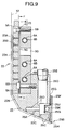
- the tacking member 22 further has film suction grooves 23A and 25A (Fig. 9) formed in the vertical surface 22A and the first and second beveled surfaces 22B, 22C for holding the laminated film 12 by suction on the above surfaces 22A - 22C.
- a half-cut device 28 is disposed upstream of the tacking member 22 and movable on the path 13 of the laminated film in the widthwise or transverse direction of the laminated film 12 for cutting or severing the cover film 12C and the photosensitive layer 12B of the laminated film 12, with the base film 12A left uncut.
- An adhesive tape supplying device 32 is disposed adjacent to the tacking member 22 for supplying an adhesive tape 30 in the direction of movement of the laminated film 12 in parallel relation to the laminated film 12.
- the adhesive tape supplying device 32 is located at a position close to each of the opposite longitudinal edges of the laminated film 12 so that two adhesive tapes 30 are supplied in confronted relation to the opposite longitudinal edges of the laminated film 12.
- the adhesive tapes 30 supplied from the adhesive tape supplying devices 30 are wound around a presser roll 34 with its adhesive side facing outward.
- the presser roll 34 is disposed along the laminated film 12 in the widthwise direction of the same and rollingly engageable with the first and second beveled surfaces 22B and 22C of the tacking member 22.
- the presser roll 34 is rotatably supported by a presser roll actuating device 36.
- the presser roll actuating device 36 is constructed such that the presser roll 34 forced by the presser roll actuating device 36 against the leading end of the tacking member 22 rolls on from the first beveled surface 22B to a leading end of the second beveled surface 22C to force the adhesive tapes 30 into adhesion with the cover film 12C of the laminated film 12 while being held by suction on the first and second beveled surfaces 22B and 22C.
- the presser roll actuating device 36 is also operable to retract or move the presser roll 34 away from the position of the leading end of the second beveled surface 22C.
- the presser roll actuating device 36 is provided with an adhesive-tape pullback means 38 for pulling the adhesive tapes 30 in a direction away from the first and second beveled surfaces 22B and 22C in synchronism with the movement of the presser roll 34 when the presser roll 34 is retracted away from the second beveled surface 22C.
- the film applying apparatus 10 further includes a film-and-tape take-up device 40 disposed at an upper end of the film applying apparatus 10 for taking up the adhesive tapes 30 and that portion of the cover film 12C bonded with the adhesive tapes 30 and separated from the base film 12A and the photosensitive layer 12B as the adhesive tapes 30 are pulled in the direction away from the first and second beveled surfaces 22B and 22C.
- reference character 42 denotes a rotary cutter composed of a rotary knife 42A and a stationary knife 42B cooperating to cut or sever the laminated film 12 lying on the path 13.
- the rotary knife 42A has a helical cutting edge provided on the periphery of a cylindrical shaft
- the stationary knife 42B has a straight cutting edge extending parallel to an axis of the cylindrical shaft of the rotary knife 42A.
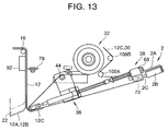
- the presser roll actuating device 36 comprises, as shown in FIG. 2, a support shaft 44 disposed in parallel relation to the presser roll 34 and having a circular cross section, an adjustment frame 46 supported on the support shaft 44 at a position confronting to a substantially widthwise central portion of the film path 13, a support frame 48 pivotally mounted on the support shaft 44 in such a manner as to surround opposite sides and the bottom of the adjustment frame 46 and pivotally movable about an axis of the support shaft 44, the support frame 48 extending in opposite directions along the support shaft 44, a pair of linear shafts (one being shown) 50 reciprocally mounted on opposite longitudinal end portions of the support frame 48 for reciprocating movement toward and away from the first beveled surface 22B and rotatably supporting at their front end the presser roll 34, a pair of actuators (one being shown) 52 for reciprocating the linear shafts 50 in the axial direction thereof, a roll-urging spring 54 disposed between the adjustment frame 46 and the support frame 48, as shown on enlarged scale in FIG.
- Reference character 56 shown in FIGS. 2 and 3 denotes an adjustment screw for adjusting a preset load on the roll-urging spring 54.
- the adjustment frame 46 is fastened to a flat cutout portion of the cylindrical support shaft 44 formed at a longitudinal central portion of an upper side of the support shaft 44.
- the support frame 48 is arranged with the aid of the adjustment frame 46 and has a connecting portion 48A extending across a lower side of the adjustment frame 46, as shown in FIG. 3, and a stopper surface 48B defined by an upper end of the connecting portion 48A and held in abutment with the underside of the adjustment frame 46, as shown in FIG. 3.
- the support frame 48 urged by the roll-urging spring 54 to turn about an axis of the support shaft 44 in the clockwise direction in FIG. 3 is normally held in a forced or biased state or condition the stopper surface 48B abuts on the underside of the adjustment frame 46.
- the support frame 48 is pivotally movable in the counterclockwise direction in FIG. 3 against the force of the roll-urging spring 54 when it is subjected to a force greater than a predetermined value and tending to urge the support frame 48 in the counterclockwise direction.
- the support frame 48 has a pair of bearings 60 disposed each at a portion located closer to a center of the support frame 48 than a portion on which a corresponding one of the actuators 52 is mounted.
- the linear shafts 50 mounted in parallel relation to the actuators 52 are slidably and axially reciprocally supported by the bearings 60.
- the linear shafts 50 each have an end opposite to the presser roll 34 and joined with a joint member 64 connected to an actuating portion 52A of the actuator 52.
- the adhesive-tape pullback means 38 includes a pair of guide shafts (one being shown) 66 coaxial with the linear shafts 50 and projecting respectively from the joint members 64 in a direction away from the linear shafts 50, a pair of bearing members (one being shown) 68 slidably supported on the guide shafts 66, a pair of film pullback springs (one being shown) 70 urging the bearing members 68 in a direction away from the joint members 64, and a dancer roll 72 rotatably supported at its opposite ends in the londitudinal direction thereof by the bearing members 68.
- the guide shafts 66 are formed as an extension of each linear shaft 50 projecting from the joint member 64.
- the film pullback springs 70 have a spring force which is set to allow the film pullback springs 70 to yield or deform into an axially contracted shape by a tension applied to the adhesive tapes 30 when the presser roll 34 is advanced by the presser roll actuating device 36.
- the dancer roll 72 guides therearound a portion of the adhesive tapes 30 and the cover film 12C bonded thereto extending from the presser roll 34 to the film-and-tape take-up device 40.
- the slackening device 2 includes a bracket 2A supported on an end portion of each guide shaft 66 projecting from the bearing member 68, and a pushing cylinder 2B composed of an air cylinder supported on the bracket 2A.
- the pushing cylinder 2B includes an actuating rod 2C having an outer end held in abutment with the bearing member 68 from the direction opposite to the film pullback spring 70.
- the film tensioning device 1 includes a pair of lift-up cylinders 1A composed of air cylinders vertically disposed below the tension roll 16A, as shown in FIG. 1, and having a pair of actuating rods 1B, respectively, engageable with opposite end portions of a shaft of the tension roll 16A for lifting up the tension roll 16A.
- the film tensioning mechanism 16 includes a pivot arm 16B rotatably supporting at its one end the tension roll 16A, and a spring 16C urging the opposite end of the pivot arm 16B downward in FIG. 1 to tension or stretch the laminated film 12 by the tension roll 16A.
- reference character 16D denotes an adjustment mechanism for adjusting a preset load on the spring 16C.
- the film pullback springs 70 have a spring constant which is greater than the spring constant of the spring 16C of the film tensioning mechanism 16.
- the presser roll 34 can be advanced by the pushing cylinders 2B to such an extent that the presser roll 34 does not reach the path 13 of the laminated film 12 even when it moved forward or advanced while the presser roll 34 is held in a standby state or condition after the cover film 12C is separated.
- the half-cut device 28 as shown on enlarged scale in FIGS. 4 and 5, comprises a disk cutter 78 rotatable in a plane perpendicular to the laminated film 12 and reciprocally movable in the widthwise direction of the laminated film 12, and a pair of guide rolls 80 disposed in juxtaposition on opposite sides of the disk cutter 78 as viewed from the direction of movement of the disk cutter 78 and rotatable in a plane parallel to a plane of rotation of the disk cutter 78.
- the guide rolls 80 have peripheral surfaces jointly defining a common tangent plane facing the laminated film, the common tangent plane being substantially tangent to a cutting edge 78A of the disk cutter 78.
- the half-cut device 28 further includes a rodless cylinder 82 of the type having a built-in guide and disposed along the laminated film 12 in the widthwise direction of the same, a slide member 84 supported by the rod-less cylinder 82 and reciprocally movable by the rod-less cylinder 82 in the widthwise direction of the laminated film 12, the slide member 84 supporting thereon the guide rolls 80, a movable member 86 supporting thereon the disk cutter 78 and supported by the slide member 84 such that the movable member 86 is reciprocally movable in the widthwise direction of the laminated film 12 within a predetermined range of distance, a spring 88 acting between the movable member 86 and the slide member 84 to urge the movable member 86 toward the laminated film 12, and a micrometer 90 acting as a spring adjustment means for adjusting a set length of the spring 88.
- a rodless cylinder 82 of the type having a built-in guide and disposed along the laminated film 12 in the widthwise direction of
- the half-cut device 28 further includes a cutter backup plate 92 made of metal or rigid plastic and disposed at a position opposite to a path of movement of the dish cutter 78 across the laminated film 12 so as to retain the disk cutter 78 when the disk cutter 78 is forced against the backup plate 92 with the laminated film 12 lying therebetween.
- a cutter backup plate 92 made of metal or rigid plastic and disposed at a position opposite to a path of movement of the dish cutter 78 across the laminated film 12 so as to retain the disk cutter 78 when the disk cutter 78 is forced against the backup plate 92 with the laminated film 12 lying therebetween.
- the rod-less cylinder 82 and cutter backup plate 92 are commonly supported on a single unit frame 94.
- the unit frame 94 is laid parallel to the presser roll 34 and extends transversely across the width of the film applying apparatus 10. As shown in FIG. 6, the unit frame 94 is fixed at its opposite ends to confronting sidewalls (one being shown) 96 of the apparatus.
- the slide member 84 as shown in FIG. 4, has an upper end secured to the rod-less cylinder 82, the other end of the slide member 84 including a projection 84A projecting downwardly beyond the movable member 86 and extending transversely across the underside of the movable member 86.
- the projection 84A extending transversely across the underside of the movable member 86 has opposite end portions projecting laterally outwardly from the movable member 86, and a pair of parallel spaced guide-roll supporting members 98 is attached at one end to the opposite end portions of the projection 84A and rotatably supports at the other end the guide rolls 80.
- the movable member 86 is disposed between the pair of guide-roll supporting members 98 and slidable relative to the slide member 84 via a slide shoe 86A.
- the spring 88 acts between the projection 84A of the slide member 84 and a spring retainer 86B projecting downwardly from the movable member 86, as shown in FIG. 4, and urges the movable member 86 in the left-hand direction in FIG. 4 with respect to the projection 84A.
- Reference characters 88A and 88B shown in FIGS. 4 and 5 denote a bolt and a nut, respectively, used for adjusting a set length of the spring 88.
- the micrometer 90 is attached to the movable member 86 and has a spindle 90A extending in a space defined between the guide-roll supporting members 98 and having a front end engageable with an end face 84B of the slide member 84 to limit movement of the movable member 86 in the right-hand direction in FIGS. 4 and 5 which is taken against the force of the spring 88.
- each of the adhesive tape supplying devices 32 is movably supported on the unit frame 94 via a slide mechanism 100 and movable parallel to the presser roll 34 within a predetermined range of distance.
- the slide mechanism 100 includes a slide bar 100A extending parallel to the presser roll 34, a slide member 100B slidably mounted on the glide bar 100A and supporting thereon a brake 102, and a set screw 100C for fastening the slide member 100B to the slide bar 100A at a desired position along the slide bar 100A.
- a roll holder 106 is attached to the brake 102 for rotatably and detachably holding an adhesive tape roll 104.
- the brake 102 serves to control or slow down the speed of rotation of the roll holder 106 to exert a tension greater than a predetermined value on each adhesive tape 30 when the adhesive tape 30 is unwound from the adhesive tape roll 104.
- reference characters 108A and 108B denote a pair of guide rolls for guiding the cover film 12C and the adhesive tapes 30 as they travel from the dancer roll 72 to the film-and-tape take-up device 40.
- the guide rolls 108A, 108B are secured to the unit frame 94 via a pair of support plates (one being shown) 110.
- the support shaft 44 of the presser roll actuating device 36 has opposite ends attached to the sidewalls 96 of the apparatus via an advancing/retracting mechanism 112, as shown in FIGS. 7 and 8, so that the support shaft 44 is movable back and forth within a predetermined range of distance in a direction perpendicular to the vertical surface 22A of the tacking member 22.
- the advancing/retracting mechanism 112 includes a slide member 112A slidably supporting each end of the support shaft 44, a guide shaft 112B slidably supporting the slide member 112A in a plane perpendicular to the vertical surface 22A, a second guide shaft 112C attached to the slide member 112A and parallel with the guide shaft 112B, and a fastening member 112E slidably guiding the second guide shaft 112C within a predetermined range of distance, the fastening member 112E being adapted to be securely fastened to the second guide shaft 112C when it is tightly fastened by a tightening handle 112D.
- the range of movement of the support shaft 44 and all members supported on the support shaft 44 in a direction perpendicular to the vertical surface 22A, which is attained by the advancing/retracting mechanism 112, is defined by and between the position of the support shaft 44 indicated by the solid line shown in FIG. 1 and the position of the support shaft 44 indicated by the two-dot chain line shown in the same figure.
- the solid-lined position shown in FIG. 1 is a normal operating (setting) position, while the two-dot chain-lined position shown in the same figure is a retracted position which is provided to facilitate manual setting of the laminated film 12 and maintenance of the rotary cutter 42 and the tacking member 22.
- the tacking member 22 is composed of a flat main vacuum plate 23 laid parallel with the path 13 (FIG. 1) of the laminated film 12 and having the plurality of film suction grooves 23A formed in a front surface of the main vacuum plate 23, and a film-tacking member body 25 connected to a leading end, as viewed in the direction of feed of the laminated film 12, of the main vacuum plate 23 and having a front surface extending contiguously and obliquely from the front surface of the main vacuum plate 23 and having formed therein the plurality of film suction grooves 25A.
- the film-tacking member body 25 has a heater 25K embedded in the vicinity of a leading end portion 25B, as viewed in the direction of feed of the laminated film 12, of the film-tacking member body 25 for heating the leading end portion 25B.
- the main vacuum plate 23 is composed of a suction plate 4 having a front surface facing the path of the laminated film 12 and formed with the film suction grooves 23A, and a backup member 5 attached by screws 5B to the back of the suction plate 4 with a frame-like heat-resistant rubber packing or gasket 5A disposed therebetween.
- three parallel spaced pipes 6A pass through the backup member 5 in a direction transverse to the direction of feed of the laminated film 12.
- the pipes 6A are parallel with the film path 13 (FIG. 1) and each define a water passage hole 6B.
- the backup member 5 further has a plurality of inlet ports 6C formed in a perpendicular direction of the water passage holes 6B for introducing therefrom a cooling water into the water passage holes 6B.
- the cooling water thus introduced flows along the water passage holes 6B in the widthwise direction of the laminated film 12 and thereafter is discharged from a plurality of outlet ports 6D located at an end of the water passage holes 6B remote from the inlet ports 6C.
- the heat-resistant rubber packing 5A has a plurality of vacuum spaces 5C arranged in the widthwise direction of the laminated film. Each of the vacuum spaces 5C is communicated with a vacuum source (not shown) via a vacuum port 5D extending through the thickness of the backup member 5 and located substantially at a central portion of the vacuum space 5C.
- the film suction grooves 23A formed in the suction plate 4 extend in a direction transverse to the film feed direction and are spaced in the film feed direction.
- Each of the film suction grooves 23A has a plurality of vacuum holes 23B connected at one end to the film suction groove 23A and opening at the other end to the vacuum space 5C.
- the film-tacking member body 25 has the aforesaid first and second beveled surfaces 22B and 22C extending contiguously and obliquely from the front surface (vertical surface 22A) of the main vacuum plate 23.
- the film suction grooves 25A are formed in the first and second beveled surfaces 22B, 22C and extend in a direction transverse to the direction of feed of the laminated film 12.
- the tacking member 22 has, at its base plate 20 side, a leading end portion which includes the aforesaid vertical surface 22A forming the front surface of the suction plate 4 and extending along the path 13 of the laminated film 12, the aforesaid first beveled surface 22B extending obliquely from a leading end of the vertical surface 22A in a direction away from the path 13, and the aforesaid second beveled surface 22C extending obliquely from a leading end of the first beveled surface 22B in a direction away from the path 13.
- the film suction grooves 25A formed in the first and second beveled surfaces 22B and 22C each communicate with a plurality of vacuum holes 25C arranged at appropriate intervals along the longitudinal direction of the film suction groove 25A.
- the vacuum holes 25C communicate with internal vacuum channels 25D of the film-tacking member body 25.
- the vacuum channels 25D is connected to the vacuum source (not shown) via a vacuum pipe 25E.
- the lending end portion 25B of the film-tacking member body 25 is a lower end of a block member 25F, and the heater 25K is embedded in the block member 25F.
- the block member 25F is coupled with the film-tacking member body 25 with a heat-resistant rubber seal 25G disposed therebetween.
- the lower end of the block member 25F, i.e., the leading end 25B is composed of a heat-resistant rubber piece 25H having a generally triangular cross section.
- the block member 25F for its attachment, is fitted with a plurality of mounting grooves 25J formed in the back of the film-tacking member body 25 and aligned with one another in the transverse direction of the laminated film 12.
- the film applying apparatus 10 in the embodiment described above will operate as follows.
- the support shaft 44 is retracted by the advancing/retracting mechanism 112 to the position indicated by the two-dot chain line shown in FIG. 1, so as to define, between the presser roll 34 and the tacking member 22, a space for the passage therethrough of a laminated film 12.
- the support shaft 44 is set by the advancing/retracting mechanism 112 to the advanced position indicated by the solid line shown in FIG. 1.
- the contact pressure or force exerted from the presser roll 34 onto the first and second beveled surfaces 22B and 22C is adjusted to balance throughout the width of the presser roll 34.
- the support frame 48 supporting the opposite ends of the presser roll 34 extends parallel with the presser roll 34 and is attached substantially at its central portion to the support shaft 44, the contact pressure adjustment work can be achieved easily.
- cooling water is introduced into the water passage holes 6B in the main vacuum plate 23 of the tacking member 22 for cooling the suction plate 4.
- the laminated film 12 extends downward from vertical surface 22A of the tacking member 22 to the second beveled surface 22C across the first beveled surface 22B.
- the thus supplied laminated film 12 is locked in the condition illustrated in FIG. 11 by the action of a negative pressure or suction created on the surfaces 22A - 22C in the vicinity of the suction grooves in the tacking member 22.
- the half-cut device 28 is activated to cut or sever the cover film 12 and the photosensitive layer 12B at an upstream position determined to ensure that a desired length of the photosensitive layer 12B can be exposed in a subsequent cover-film separating or peeling process.
- the half-cut device 28 may slightly cut in the base film 12A.
- the foregoing half-cut process is achieved by activating the rod-less cylinder 82 of the half-cut device 22 to move the slide member 84 in the widthwise or transverse direction of the laminated film 12 while rotating disk cutter 78.
- the disk cutter 78 bites into the cover film 12C and the photosensitive layer 12B and severs them transversely with laminated film 12 held between the disk cutter 78 and the cutter backup plate 92.
- the guide rolls 80 disposed in front and in the rear of the disk cutter 78 as viewed from the direction of movement of the disk cutter 78 and having the same position as the cutting edge 78A of the disk cutter 78 as viewed from the direction of the thickness of the laminated film 12, continuously force the laminated film 12 against the cutter backup plate 92.
- the laminated film 12 while being severed can, therefore, be held stably in position without displacement with the result that the disk cutter 78 can only sever the cover film 12C and the photo-conductive layer 12B.
- the disk cutter 78 is retracted when the front or leading guide roll 80 runs on an edge of the cutter backup plate 92, for example, there is no possibility of breaking or otherwise damaging the cutting edge 78A of the disk cutter 78 due to collision with the cutter backup plate edge.
- the cutter backup plate 92 is made of rigid plastic or metal, the laminated film 12 a whole is unlikely to become distorted while the disk cutter 78 is undertaking a limited severance of the cover film 12 and the photosensitive layer 12B.
- the cutter backup plate 92 made of such a rigid material as specified above also enables a fine adjustment of the cutting depth taken by the disk cutter 78, which will ensure a precision cutting effected exclusively against the cover film 12C and the photosensitive layer 12B.
- the actuators 52 of the presser roll actuating device 36 are driven to advance the linear shafts 50 and the presser roll 34 supported thereon, thereby causing the presser roll 34 to roll on from the first beveled surface 22B to a leading end of the second beveled surface 22 of the tacking member 22 while continuously forcing the adhesive tapes 30 against the cover film 12C (see FIG. 12).
- the brakes 102 (FIG. 6) of the adhesive tape supplying device 32 are activated to lock the roll holders 106 to limit unwinding of the adhesive tapes 30 with the result that the adhesive tapes 30 are fed back or supplied from the film-and-tape take-up device 40 side via the dancer roll 72.
- the adhesive tapes 30 supplied toward the first and second beveled surfaces 22B and 22C force the dancer roll 72 in a direction to compress the film pullback springs 70.
- a path along which the adhesive tapes 30 are supplied can be reduced.
- the actuators 52 are driven to return the presser roll 34 to the initial position via the linear shafts 50.
- the adhesive tapes 30 are pulled back as the film pullback springs 70 urging the dancer roll 72 restore their original length.
- the cover film 12C adhering to the adhesive tapes 30 is peeled off or separated from the base film 12A and the photosensitive layer 12B.
- the tacking member 22 is lowered so that the base film 12A and the photosensitive layer 12B while being held by suction on a leading end of the tacking member 22 are temporarily attached or tacked on a leading end portion of a base plate 20 with the photosensitive layer 12B sandwiched between the base film 12A and the base plate 20.
- the film-and-tape take-up device 40 is driven to take up the adhesive tapes 30 and the cover film 12B bonded thereto.
- the adhesive tape supply device 32 unwinds the adhesive tapes 30 while applying a constant tension to the adhesive tapes 30 by the action of the brakes 102.
- the laminated film 12 could be pulled upwardly without being attracted to the tacking member 22.
- the cover film 12C is adhered to the adhesive tapes 30, and since the adhesive tapes 30 are held immovable between the adhesive tape supplying device 32, the presser roll 34, the dancer roll 72 and the film-and-tape take-up device 40, the laminated film 12 is also held in the immovable condition.
- the tension roll 16A of the film tension mechanism 16 is urged upwardly by the spring 16C, it is not possible to pull the laminated film 12 upwardly against the force of the film pullback springs 70 as long as the spring constant of the spring 16C is smaller than the spring constant of the film pullback springs 70.
- each pushing cylinder 2B of the slackening device 2 is activated so that the actuating rod 2C of the pushing cylinder 2B pushes or forces the corresponding hearing member 68 in a direction toward the presser roll 34 against the force of the film pullback spring 70.
- the lift-up cylinders 1A are driven so that the actuating rods 1B of the respective lift-up cylinders 1A lift the opposite ends of the tension roll 16A upwardly in FIG. 15, thereby pulling the laminated film 12 upwardly.
- the laminated film 12 which has been left slackened after tacking is pulled up-wardly to such an extent that a subsequent pressure-bonding process by the lamination rolls 24 can be achieved satisfactorily without involving generation of wrinkles or bubbles as previously described.
- the stroke of the pushing cylinders 2B is so adjusted as to permit the laminated film 12 to be pulled upwardly until it assumes the position of the laminated film 12 indicated by the two-dot chain lines shown in FIG. 15.
- the lift-up cylinders 1A of the film tensioning device 1 are constructed such that the actuating rods 1B return to their retracted position immediately after they lifted up the tension roll 16A. Since the tension roll 16A supported on the pivot arm 16B is urged upwardly (i.e., in a direction to tension or stretch the laminated film 12) by the spring 16C, descending movement of the tension roll 16A toward the base plate 20 does not occur even when the lift-up cylinders 1A are activated to contract their actuating rods 1B.
- the rotary cutter 42 is driven to cut or sever the laminated film 12 transversely at a position which, as shown in FIG. 15, is higher than, i.e., upstream of, a cutting line already formed in the cover film 12C (and also in the photosensitive layer 12B) by the disk cutter 78.
- a cover film 12C of a fixed length is left at a trailing end side of the base film 12A and the photosensitive layer 12B.
- the length of this cover film 12C is determined such that the cover film 12C projects from the trailing end 20A of the base plate 20 by a fixed distance in the range of 1 to 2 cm, for example, as shown in FIG. 17.
- a portion of the photosensitive layer 12B projecting from the trailing end 20A of the base plate 20 is sandwiched between the base film 12A and the cover film 12C.
- a projecting portion having a threeply structure of the laminated film can be gripped by a nipping device (not shown) and hence is able to facilitate separation of the base film 12A which is achieved subsequently by using the nipping device.
- the photosensitive layer 12B is not exposed but covered by the cover film 12C and hence the base film separating process can be achieved smoothly without involving a problem which would otherwise be caused due to adhesion between the photosensitive layer 12B and the nipping device.
- cooling water is continuously introduced into the water passage holes 6B in the main vacuum plate 23 of the tacking member 22 and, hence, the suction plate 4 is cooled and does not reach a high temperature.
- the lamination film 12 held by suction on the thus cooled suction plate 4 is, therefore, free from a problem caused from the effect of high temperatures, such as non-uniform heat history, uneven thickness or unstable viscosity of the photosensitive resin layer 12B.
- the photosensitive resin layer 12B is stable in viscosity, so that when the cover film 12C is separated by the adhesive tapes 30 from the photosensitive resin layer 12B and the base film 12A, the peeling moves smoothly and continuously. The separation can, therefore, he achieved smoothly with no transverse wrinkle formed on the photosensitive resin layer 12B.
- the tacking member 22 does not reach a high temperature, no recessed pattern is formed on the laminated film 12 and the bane film 12A, in particular while the laminated film 12 is held by suction on the tacking member 22 formed with the film suction grooves 23A, 25A.
- the photosensitive resin layer 12B is kept uniform in thickness.
- the photosensitive resin layer 12B is uniform in thickness, has a uniform heat history, is stable in viscosity and is free from surface irregularities. Accordingly, a wiring pattern formed on the base plate after exposure and development of the photosensitive layer has a uniform width and free from a development failure such an an intrusion, a mouse nip or a break.
- the slackening device 2 is so constructed as to force the dancer roll 72 toward the presser roll 34, thereby providing a slack on the adhesive tapes 30 and the cover film 12C adhered thereto.
- This invention should by no means be limited to the illustrated embodiment but may include any arrangement in which the adhesive tapes 30 and the cover film 12C are slackened between the presser roll 34 and the film-and-tape take-up device 40.
- a tension roll is disposed between the dancer roll 72 and the film-and-tape take-up device 40.
- the tension roll normally elongates the length of a film path but can provide a slack on the adhesive tapes 30 and the cover film 12C when it is displaced in a direction to reduce the film path.
- the actuators used for providing a slack should by no means be limited to the cylinders but may be replaced by motors.
- the slackening device 2 operates to slack the adhesive tapes 30 and the cover plate 12C, and the film tensioning device 1 operates to pull or stretch the laminated film 12 either at the same time as, or subsequent to, the slackening operation of the slackening device 2.
- the present invention is not limited to this embodiment but may includes a variation in which the laminated film 12 is pulled or stretched by the film tensioning device 1 with no slack provided by the slackening device. In this instance, the dancer roll 72 is forced by the adhesive tapes 30 and the cover film 12C to displace toward the presser roll 34 against the force of the film pullback springs 72.
- the lift-up cylinder 1A of the film tensioning device 1 is normally composed of an air or pneumatic cylinders which may be replaced by an oil hydraulic cylinder, a hydraulic cylinder or a gas cylinder. Suitable actuators other than the cylinder may include a motor.
- the half-cut device 28 in the above-described embodiment includes a slide member 84 driven by the rod-less cylinder 82.
- the present invention should by no means be limited to this arrangement but may include a modification in which the slide member 84 is reciprocated in the widthwise direction of the laminated film by means of a drive unit such as a belt drive unit, a chain drive unit or a screw shaft.
- the laminated film 12 is urged by the film tensioning mechanism 16 in a direction to pull back or stretch the laminated film 12, and while keeping this condition, and prior to the start of the film pressure-bonding operation by the lamination rolls 24, the film tensioning device 1 operates to drive or force the film tensioning mechanism 16 in a direction to pull back the laminated film by a predetermined distance.
- the slackening device 2 operates to slacken the cover film 12C (including adhesive tapes 39), thereby enabling the laminated film 12 to be pulled backward.
- the present invention is not limited to this arrangement but may include another arrangement suitable for an application in which only a slight slack is produced immediately after the laminated film 12 is tacked to the base plate 20 by the tacking member 20, as shown in FIG. 19.
- the arrangement shown in FIG. 19 differs from the first embodiment shown in FIG. 1 in that the film tensioning mechanism 16, the film tensioning device 1 and the slackening device 2 are omitted.
- the water passage holes 6B are formed in the main vacuum plate 23.
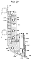
- This invention should by no means be limited to this embodiment but may includes another embodiment shown in FIG. 20 in which a water passage hole 6B is defined by a pipe 6A placed in the film-tacking member body 25.
- two cooling rolls 7 each defining therein a water passage hole 6B are disposed in such a position that the laminated film 12 is gripped between the cooling rolls 7 and the tacking member 22.
- the number of the cooling rolls may be one or alternately three or more, and they may be disposed in a position in the vicinity of the tacking member 22 including an upstream side of the tacking member 22.
- the arrangement shown in FIG. 20 insures an efficient cooling because the laminated film 12 is cooled from its both sides.
- the water passage holes 6B are each composed of a pipe.
- the water passage holes are formed directly in the tacking member 22.
- the pipes are preferably made of a corrosion-resistant material such as stainless steel.
- the tacking member 22 is preferably made of a material such as anodized aluminum which is inferior in corrosion-resistance to the stainless steel but superior in heat conductivity to the stainless steel.
- the water passage holes are supplied with water as a cooling fluid.
- another cooling fluid such as cooling oil or alcohol may be used. It is preferable that the cooling fluid is of the type capable of maintaining the surface of the suction plate 4 of the main vacuum plate 23 at a temperature in the range of 20 - 30°.
Landscapes
- Physics & Mathematics (AREA)
- General Physics & Mathematics (AREA)
- Fluid Mechanics (AREA)
- Engineering & Computer Science (AREA)
- Manufacturing & Machinery (AREA)
- Lining Or Joining Of Plastics Or The Like (AREA)
- Manufacturing Of Printed Circuit Boards (AREA)
- Folding Of Thin Sheet-Like Materials, Special Discharging Devices, And Others (AREA)
Applications Claiming Priority (4)
| Application Number | Priority Date | Filing Date | Title |
|---|---|---|---|
| JP17080/95 | 1995-02-03 | ||
| JP7017080A JP2993655B2 (ja) | 1995-02-03 | 1995-02-03 | フィルム張付装置 |
| JP7165198A JP2993657B2 (ja) | 1995-06-30 | 1995-06-30 | フィルム張付方法及び装置 |
| JP165198/95 | 1995-06-30 |
Publications (3)
| Publication Number | Publication Date |
|---|---|
| EP0725559A2 true EP0725559A2 (de) | 1996-08-07 |
| EP0725559A3 EP0725559A3 (de) | 1996-10-16 |
| EP0725559B1 EP0725559B1 (de) | 1998-07-01 |
Family
ID=26353548
Family Applications (1)
| Application Number | Title | Priority Date | Filing Date |
|---|---|---|---|
| EP96101082A Expired - Lifetime EP0725559B1 (de) | 1995-02-03 | 1996-01-25 | Verfahren und Vorrichtung zum Aufbringen eines Films auf eine Oberfläche |
Country Status (5)
| Country | Link |
|---|---|
| US (1) | US5772839A (de) |
| EP (1) | EP0725559B1 (de) |
| KR (1) | KR100303415B1 (de) |
| DE (1) | DE69600379T2 (de) |
| TW (1) | TW283819B (de) |
Cited By (4)
| Publication number | Priority date | Publication date | Assignee | Title |
|---|---|---|---|---|
| WO2000059816A1 (en) * | 1999-03-30 | 2000-10-12 | Sustainable Technologies International Pty Ltd | Methods to manufacture single cell and multi-cell regenerative photoelectrochemical devices |
| AU767569B2 (en) * | 1999-03-30 | 2003-11-13 | Dyesol Ltd | Methods to manufacture single cell and multi-cell regenerative photoelectrochemical devices |
| CN102087925A (zh) * | 2010-12-31 | 2011-06-08 | 东莞东聚电子电讯制品有限公司 | 一种按键贴合机 |
| CN112173833A (zh) * | 2020-09-26 | 2021-01-05 | 岳红宾 | 一种交通反光膜全自动无痕贴膜机 |
Families Citing this family (11)
| Publication number | Priority date | Publication date | Assignee | Title |
|---|---|---|---|---|
| TW537970B (en) * | 2001-03-05 | 2003-06-21 | Hitachi Ind Co Ltd | Laminator |
| JP2004333616A (ja) * | 2003-05-01 | 2004-11-25 | Fuji Photo Film Co Ltd | 感光性樹脂転写装置および方法 |
| WO2005100220A1 (ja) | 2004-04-13 | 2005-10-27 | Beac Co., Ltd. | カバーレイフィルム貼り合わせ装置 |
| JP2005347618A (ja) * | 2004-06-04 | 2005-12-15 | Fuji Photo Film Co Ltd | 感光性ウエブユニット、感光性積層体の製造装置及び製造方法 |
| JP4780559B2 (ja) | 2005-12-14 | 2011-09-28 | 株式会社日立プラントテクノロジー | フィルム貼付方法およびその装置 |
| KR100818150B1 (ko) * | 2007-06-20 | 2008-03-31 | 유신단열 주식회사 | 유리섬유 단열재 측면 필름부착장치 |
| CN101963710B (zh) * | 2009-07-24 | 2014-02-19 | 鸿富锦精密工业(深圳)有限公司 | 贴合设备 |
| KR101926051B1 (ko) * | 2016-11-23 | 2018-12-06 | 주식회사 조성 | 접착필름-기판 본딩 공정시스템 |
| KR102287615B1 (ko) * | 2019-09-18 | 2021-08-10 | 주식회사 인지디스플레이 | 인슐레이션 어태치 장치 |
| GB2588644B (en) * | 2019-10-30 | 2023-09-06 | Jjs Application Tech Ltd | Adhesive tape dispenser |
| CN114654802B (zh) * | 2022-03-23 | 2023-11-03 | 重庆市恒合包装股份有限公司 | 一种瓦楞彩箱表面彩印膜贴附装置 |
Citations (4)
| Publication number | Priority date | Publication date | Assignee | Title |
|---|---|---|---|---|
| DE3339723A1 (de) * | 1983-11-03 | 1985-05-23 | Löhr & Herrmann Ingenieurgesellschaft mbH, 7531 Neuhausen | Verfahren und vorrichtung zum abloesen der schutzfolie von laminierten leiterplatten |
| EP0330339A2 (de) * | 1988-02-26 | 1989-08-30 | Morton International, Inc. | Trockenphotolackfilm für die Herstellung von Konformmasken und Verfahren zur Herstellung einer gedruckten Schaltung |
| US4880488A (en) * | 1985-08-16 | 1989-11-14 | Somar Corporation | Film peeling method and apparatus |
| US5106450A (en) * | 1990-12-20 | 1992-04-21 | International Business Machines Corporation | Dry film resist transport and lamination system for semiconductor wafers |
Family Cites Families (7)
| Publication number | Priority date | Publication date | Assignee | Title |
|---|---|---|---|---|
| US3277760A (en) * | 1965-01-25 | 1966-10-11 | Grace W R & Co | Apparatus for severing a web |
| US3360174A (en) * | 1965-10-11 | 1967-12-26 | Honeywell Inc | Web follower arm |
| DE1915600C2 (de) * | 1969-03-27 | 1984-04-26 | Enka Ag, 5600 Wuppertal | Schneidvorrichtung für Maschinen mit hin- und hergehender Messerbewegung zum Schneiden von Faserkabeln, Folien u.dgl. |
| JPH03147833A (ja) * | 1989-11-04 | 1991-06-24 | Somar Corp | 薄膜張付方法及びその実施装置 |
| CA2100014C (en) * | 1992-07-14 | 1999-12-28 | Fuminori Murakami | Paper cutting device using a movable cutting wheel |
| US5437960A (en) * | 1993-08-10 | 1995-08-01 | Fuji Photo Film Co., Ltd. | Process for laminating photosensitive layer |
| JP3234702B2 (ja) * | 1994-01-12 | 2001-12-04 | 富士写真フイルム株式会社 | 感光層積層装置 |
-
1996
- 1996-01-13 TW TW085100367A patent/TW283819B/zh active
- 1996-01-15 KR KR1019960000952A patent/KR100303415B1/ko not_active IP Right Cessation
- 1996-01-25 DE DE69600379T patent/DE69600379T2/de not_active Expired - Fee Related
- 1996-01-25 EP EP96101082A patent/EP0725559B1/de not_active Expired - Lifetime
- 1996-01-25 US US08/591,400 patent/US5772839A/en not_active Expired - Fee Related
Patent Citations (4)
| Publication number | Priority date | Publication date | Assignee | Title |
|---|---|---|---|---|
| DE3339723A1 (de) * | 1983-11-03 | 1985-05-23 | Löhr & Herrmann Ingenieurgesellschaft mbH, 7531 Neuhausen | Verfahren und vorrichtung zum abloesen der schutzfolie von laminierten leiterplatten |
| US4880488A (en) * | 1985-08-16 | 1989-11-14 | Somar Corporation | Film peeling method and apparatus |
| EP0330339A2 (de) * | 1988-02-26 | 1989-08-30 | Morton International, Inc. | Trockenphotolackfilm für die Herstellung von Konformmasken und Verfahren zur Herstellung einer gedruckten Schaltung |
| US5106450A (en) * | 1990-12-20 | 1992-04-21 | International Business Machines Corporation | Dry film resist transport and lamination system for semiconductor wafers |
Cited By (8)
| Publication number | Priority date | Publication date | Assignee | Title |
|---|---|---|---|---|
| WO2000059816A1 (en) * | 1999-03-30 | 2000-10-12 | Sustainable Technologies International Pty Ltd | Methods to manufacture single cell and multi-cell regenerative photoelectrochemical devices |
| EP1200325A1 (de) * | 1999-03-30 | 2002-05-02 | Dyesol Ltd | Verfahren zur herstellung von einzel- und multizellulären regenerativen photoelektrochemischen vorrichtungen |
| AU767569B2 (en) * | 1999-03-30 | 2003-11-13 | Dyesol Ltd | Methods to manufacture single cell and multi-cell regenerative photoelectrochemical devices |
| US6652904B1 (en) | 1999-03-30 | 2003-11-25 | Sustainable Technologies International Pty. Limited | Methods to manufacture single cell and multi-cell regenerative photoelectrochemical devices |
| EP1200325A4 (de) * | 1999-03-30 | 2008-12-03 | Dyesol Ltd | Verfahren zur herstellung von einzel- und multizellulären regenerativen photoelektrochemischen vorrichtungen |
| CN102087925A (zh) * | 2010-12-31 | 2011-06-08 | 东莞东聚电子电讯制品有限公司 | 一种按键贴合机 |
| CN102087925B (zh) * | 2010-12-31 | 2014-02-26 | 东莞东聚电子电讯制品有限公司 | 一种按键贴合机 |
| CN112173833A (zh) * | 2020-09-26 | 2021-01-05 | 岳红宾 | 一种交通反光膜全自动无痕贴膜机 |
Also Published As
| Publication number | Publication date |
|---|---|
| KR960033193A (ko) | 1996-09-17 |
| US5772839A (en) | 1998-06-30 |
| DE69600379T2 (de) | 1998-10-29 |
| DE69600379D1 (de) | 1998-08-06 |
| TW283819B (de) | 1996-08-21 |
| EP0725559B1 (de) | 1998-07-01 |
| EP0725559A3 (de) | 1996-10-16 |
| KR100303415B1 (ko) | 2001-11-22 |
Similar Documents
| Publication | Publication Date | Title |
|---|---|---|
| EP0725559B1 (de) | Verfahren und Vorrichtung zum Aufbringen eines Films auf eine Oberfläche | |
| US7611600B2 (en) | Sticking apparatus and sticking method | |
| US8171977B2 (en) | Sheet peeling apparatus and peeling method | |
| JPH0272032A (ja) | 熱可塑性テープ貼付装置 | |
| US7967049B2 (en) | Tape exfoliation apparatus and tape-affixing apparatus | |
| JP2907263B2 (ja) | フィルム張付装置 | |
| JP2004511110A (ja) | 印刷回路の為の板への乾式フォトレジスト膜の熱積層成形 | |
| CN212385612U (zh) | 一种含停机装置的模切件加工系统 | |
| JP4602747B2 (ja) | 貼付装置及び貼付方法 | |
| JPH0926594A (ja) | Acfテープのカッタ装置 | |
| JP7114022B2 (ja) | ストリップゴム貼付方法およびストリップゴム貼付装置 | |
| JPH05338877A (ja) | 走行カッタ式バットスプライス方法および装置 | |
| JP2000313061A (ja) | フィルム貼り付け装置 | |
| JPH11314815A (ja) | 自動テープ貼付け方法および装置 | |
| JPH07287245A (ja) | 異方性導電膜貼付装置 | |
| JP2008085176A (ja) | チップ部品分離装置 | |
| JP7129447B2 (ja) | シート供給装置およびシート供給方法 | |
| WO2022264883A1 (ja) | シート貼付装置およびシート貼付方法 | |
| JP2993655B2 (ja) | フィルム張付装置 | |
| JPH0459560A (ja) | 離型紙付接着テープの接着剤剥離方法及び離型紙付接着テープの接着剤貼付装置 | |
| JP7280087B2 (ja) | ラベル連続体製造装置及びラベル連続体の製造方法 | |
| JP2970745B2 (ja) | フィルム張付方法及び装置、フィルム付基板 | |
| US6508908B2 (en) | Method and apparatus for splicing photographic films | |
| JPH11129698A (ja) | ラミネ−ト方法 | |
| JPH04272837A (ja) | ラベル印刷機におけるフィルムラミネート装置及びその方法 |
Legal Events
| Date | Code | Title | Description |
|---|---|---|---|
| PUAI | Public reference made under article 153(3) epc to a published international application that has entered the european phase |
Free format text: ORIGINAL CODE: 0009012 |
|
| AK | Designated contracting states |
Kind code of ref document: A2 Designated state(s): DE GB |
|
| PUAL | Search report despatched |
Free format text: ORIGINAL CODE: 0009013 |
|
| AK | Designated contracting states |
Kind code of ref document: A3 Designated state(s): DE GB |
|
| 17P | Request for examination filed |
Effective date: 19970320 |
|
| GRAG | Despatch of communication of intention to grant |
Free format text: ORIGINAL CODE: EPIDOS AGRA |
|
| 17Q | First examination report despatched |
Effective date: 19970916 |
|
| GRAG | Despatch of communication of intention to grant |
Free format text: ORIGINAL CODE: EPIDOS AGRA |
|
| GRAG | Despatch of communication of intention to grant |
Free format text: ORIGINAL CODE: EPIDOS AGRA |
|
| GRAH | Despatch of communication of intention to grant a patent |
Free format text: ORIGINAL CODE: EPIDOS IGRA |
|
| GRAH | Despatch of communication of intention to grant a patent |
Free format text: ORIGINAL CODE: EPIDOS IGRA |
|
| GRAA | (expected) grant |
Free format text: ORIGINAL CODE: 0009210 |
|
| AK | Designated contracting states |
Kind code of ref document: B1 Designated state(s): DE GB |
|
| REF | Corresponds to: |
Ref document number: 69600379 Country of ref document: DE Date of ref document: 19980806 |
|
| PLBE | No opposition filed within time limit |
Free format text: ORIGINAL CODE: 0009261 |
|
| STAA | Information on the status of an ep patent application or granted ep patent |
Free format text: STATUS: NO OPPOSITION FILED WITHIN TIME LIMIT |
|
| 26N | No opposition filed | ||
| PG25 | Lapsed in a contracting state [announced via postgrant information from national office to epo] |
Ref country code: GB Free format text: LAPSE BECAUSE OF NON-PAYMENT OF DUE FEES Effective date: 20000125 |
|
| GBPC | Gb: european patent ceased through non-payment of renewal fee |
Effective date: 20000125 |
|
| PGFP | Annual fee paid to national office [announced via postgrant information from national office to epo] |
Ref country code: DE Payment date: 20010115 Year of fee payment: 6 |
|
| PG25 | Lapsed in a contracting state [announced via postgrant information from national office to epo] |
Ref country code: DE Free format text: LAPSE BECAUSE OF NON-PAYMENT OF DUE FEES Effective date: 20020801 |