EP0722012B1 - Gleisanlage für schienengebundene Fahrzeuge - Google Patents
Gleisanlage für schienengebundene Fahrzeuge Download PDFInfo
- Publication number
- EP0722012B1 EP0722012B1 EP96100188A EP96100188A EP0722012B1 EP 0722012 B1 EP0722012 B1 EP 0722012B1 EP 96100188 A EP96100188 A EP 96100188A EP 96100188 A EP96100188 A EP 96100188A EP 0722012 B1 EP0722012 B1 EP 0722012B1
- Authority
- EP
- European Patent Office
- Prior art keywords
- track system
- support plate
- track
- ballast bed
- edge
- Prior art date
- Legal status (The legal status is an assumption and is not a legal conclusion. Google has not performed a legal analysis and makes no representation as to the accuracy of the status listed.)
- Expired - Lifetime
Links
- 239000004567 concrete Substances 0.000 claims abstract description 15
- 238000011065 in-situ storage Methods 0.000 abstract description 4
- 230000015572 biosynthetic process Effects 0.000 description 10
- 239000007787 solid Substances 0.000 description 9
- 239000000463 material Substances 0.000 description 7
- XLYOFNOQVPJJNP-UHFFFAOYSA-N water Substances O XLYOFNOQVPJJNP-UHFFFAOYSA-N 0.000 description 5
- 238000009413 insulation Methods 0.000 description 4
- 239000011178 precast concrete Substances 0.000 description 4
- 239000002689 soil Substances 0.000 description 4
- 239000011230 binding agent Substances 0.000 description 3
- 239000004568 cement Substances 0.000 description 3
- 238000013461 design Methods 0.000 description 3
- 230000000694 effects Effects 0.000 description 3
- 230000035939 shock Effects 0.000 description 3
- 238000012549 training Methods 0.000 description 3
- 229910000831 Steel Inorganic materials 0.000 description 2
- 230000002745 absorbent Effects 0.000 description 2
- 239000002250 absorbent Substances 0.000 description 2
- 238000010521 absorption reaction Methods 0.000 description 2
- 230000009471 action Effects 0.000 description 2
- 230000006978 adaptation Effects 0.000 description 2
- 239000010426 asphalt Substances 0.000 description 2
- 238000012423 maintenance Methods 0.000 description 2
- 238000004519 manufacturing process Methods 0.000 description 2
- 230000009467 reduction Effects 0.000 description 2
- 239000010959 steel Substances 0.000 description 2
- 108010053481 Antifreeze Proteins Proteins 0.000 description 1
- SEQDDYPDSLOBDC-UHFFFAOYSA-N Temazepam Chemical compound N=1C(O)C(=O)N(C)C2=CC=C(Cl)C=C2C=1C1=CC=CC=C1 SEQDDYPDSLOBDC-UHFFFAOYSA-N 0.000 description 1
- 239000000853 adhesive Substances 0.000 description 1
- 238000004026 adhesive bonding Methods 0.000 description 1
- 230000001070 adhesive effect Effects 0.000 description 1
- 230000002528 anti-freeze Effects 0.000 description 1
- 230000008901 benefit Effects 0.000 description 1
- 230000008859 change Effects 0.000 description 1
- 239000002131 composite material Substances 0.000 description 1
- 238000010276 construction Methods 0.000 description 1
- 230000006735 deficit Effects 0.000 description 1
- 238000011161 development Methods 0.000 description 1
- 230000005284 excitation Effects 0.000 description 1
- 239000003292 glue Substances 0.000 description 1
- 230000035515 penetration Effects 0.000 description 1
- 238000012545 processing Methods 0.000 description 1
- 230000008707 rearrangement Effects 0.000 description 1
- 238000004064 recycling Methods 0.000 description 1
- 230000002787 reinforcement Effects 0.000 description 1
- 230000003319 supportive effect Effects 0.000 description 1
- 230000008961 swelling Effects 0.000 description 1
- 230000007704 transition Effects 0.000 description 1
Images
Classifications
-
- E—FIXED CONSTRUCTIONS
- E01—CONSTRUCTION OF ROADS, RAILWAYS, OR BRIDGES
- E01B—PERMANENT WAY; PERMANENT-WAY TOOLS; MACHINES FOR MAKING RAILWAYS OF ALL KINDS
- E01B2/00—General structure of permanent way
-
- E—FIXED CONSTRUCTIONS
- E01—CONSTRUCTION OF ROADS, RAILWAYS, OR BRIDGES
- E01B—PERMANENT WAY; PERMANENT-WAY TOOLS; MACHINES FOR MAKING RAILWAYS OF ALL KINDS
- E01B1/00—Ballastway; Other means for supporting the sleepers or the track; Drainage of the ballastway
- E01B1/008—Drainage of track
-
- E—FIXED CONSTRUCTIONS
- E01—CONSTRUCTION OF ROADS, RAILWAYS, OR BRIDGES
- E01B—PERMANENT WAY; PERMANENT-WAY TOOLS; MACHINES FOR MAKING RAILWAYS OF ALL KINDS
- E01B19/00—Protection of permanent way against development of dust or against the effect of wind, sun, frost, or corrosion; Means to reduce development of noise
-
- E—FIXED CONSTRUCTIONS
- E01—CONSTRUCTION OF ROADS, RAILWAYS, OR BRIDGES
- E01B—PERMANENT WAY; PERMANENT-WAY TOOLS; MACHINES FOR MAKING RAILWAYS OF ALL KINDS
- E01B3/00—Transverse or longitudinal sleepers; Other means resting directly on the ballastway for supporting rails
- E01B3/28—Transverse or longitudinal sleepers; Other means resting directly on the ballastway for supporting rails made from concrete or from natural or artificial stone
- E01B3/38—Longitudinal sleepers; Longitudinal sleepers integral or combined with tie-rods; Combined longitudinal and transverse sleepers; Layers of concrete supporting both rails
-
- E—FIXED CONSTRUCTIONS
- E01—CONSTRUCTION OF ROADS, RAILWAYS, OR BRIDGES
- E01F—ADDITIONAL WORK, SUCH AS EQUIPPING ROADS OR THE CONSTRUCTION OF PLATFORMS, HELICOPTER LANDING STAGES, SIGNS, SNOW FENCES, OR THE LIKE
- E01F8/00—Arrangements for absorbing or reflecting air-transmitted noise from road or railway traffic
- E01F8/0005—Arrangements for absorbing or reflecting air-transmitted noise from road or railway traffic used in a wall type arrangement
- E01F8/0017—Plate-like elements
-
- E—FIXED CONSTRUCTIONS
- E01—CONSTRUCTION OF ROADS, RAILWAYS, OR BRIDGES
- E01F—ADDITIONAL WORK, SUCH AS EQUIPPING ROADS OR THE CONSTRUCTION OF PLATFORMS, HELICOPTER LANDING STAGES, SIGNS, SNOW FENCES, OR THE LIKE
- E01F8/00—Arrangements for absorbing or reflecting air-transmitted noise from road or railway traffic
- E01F8/0005—Arrangements for absorbing or reflecting air-transmitted noise from road or railway traffic used in a wall type arrangement
- E01F8/0023—Details, e.g. foundations
-
- E—FIXED CONSTRUCTIONS
- E01—CONSTRUCTION OF ROADS, RAILWAYS, OR BRIDGES
- E01B—PERMANENT WAY; PERMANENT-WAY TOOLS; MACHINES FOR MAKING RAILWAYS OF ALL KINDS
- E01B1/00—Ballastway; Other means for supporting the sleepers or the track; Drainage of the ballastway
- E01B1/001—Track with ballast
-
- E—FIXED CONSTRUCTIONS
- E01—CONSTRUCTION OF ROADS, RAILWAYS, OR BRIDGES
- E01B—PERMANENT WAY; PERMANENT-WAY TOOLS; MACHINES FOR MAKING RAILWAYS OF ALL KINDS
- E01B1/00—Ballastway; Other means for supporting the sleepers or the track; Drainage of the ballastway
- E01B1/002—Ballastless track, e.g. concrete slab trackway, or with asphalt layers
-
- E—FIXED CONSTRUCTIONS
- E01—CONSTRUCTION OF ROADS, RAILWAYS, OR BRIDGES
- E01B—PERMANENT WAY; PERMANENT-WAY TOOLS; MACHINES FOR MAKING RAILWAYS OF ALL KINDS
- E01B2204/00—Characteristics of the track and its foundations
- E01B2204/01—Elastic layers other than rail-pads, e.g. sleeper-shoes, bituconcrete
-
- E—FIXED CONSTRUCTIONS
- E01—CONSTRUCTION OF ROADS, RAILWAYS, OR BRIDGES
- E01B—PERMANENT WAY; PERMANENT-WAY TOOLS; MACHINES FOR MAKING RAILWAYS OF ALL KINDS
- E01B2204/00—Characteristics of the track and its foundations
- E01B2204/03—Injecting, mixing or spraying additives into or onto ballast or underground
-
- E—FIXED CONSTRUCTIONS
- E01—CONSTRUCTION OF ROADS, RAILWAYS, OR BRIDGES
- E01B—PERMANENT WAY; PERMANENT-WAY TOOLS; MACHINES FOR MAKING RAILWAYS OF ALL KINDS
- E01B2204/00—Characteristics of the track and its foundations
- E01B2204/07—Drainage
-
- E—FIXED CONSTRUCTIONS
- E01—CONSTRUCTION OF ROADS, RAILWAYS, OR BRIDGES
- E01B—PERMANENT WAY; PERMANENT-WAY TOOLS; MACHINES FOR MAKING RAILWAYS OF ALL KINDS
- E01B2204/00—Characteristics of the track and its foundations
- E01B2204/13—Dowels for slabs, sleepers or rail-fixings
Definitions
- the invention relates to a track system for rail-bound Vehicles, especially railways, with one Superstructure, the rails mounted on sleepers and a die Has gravel bed supporting sleepers, and with a substructure supporting the superstructure, the one the ballast bed bearing load-bearing plate made of concrete, which on is supported by an earth structure.
- ballast track In conventional track systems is usually used as a superstructure the so-called ballast track used, in which the sleepers rest on a gravel bed. The track and the ballast bed is supported on a substructure, over which the forces exerted by the railway vehicle in be derived from the ground.
- the ballast track has proven itself so far because it is highly flexible and Possesses adaptability and is relatively simple Way to maintain.
- Precast concrete parts to form a support channel and arrange a ballast bed in the trough, that carries the tracks in a known manner and through the side parts of the support channel are supported laterally.
- the precast concrete elements are on an earth structure, i.e. the processed soil, being below the Concrete slab with a formation protection layer and a frost protection layer are trained.
- the invention has for its object a track system of the type mentioned to create a dimensionally stable Securing the rails ensures a much improved Correctability of the tracks after deformation of the subsurface or substructure and an adjustment the vibration or vibration properties to the structural conditions.
- This task is performed on a track system Art solved according to the invention in that the support plate as a continuous belt made of in-situ concrete is trained and a thickness of at least 0.40 m having.
- the vibration and vibration problems can be solved with the massive support plate according to the invention, the one uniform, monolithic body of large mass, a so-called mass body, according to the principle of a mass-spring system.
- the strength of the Carrier plate is made according to the structural conditions chosen so that effective protection against shocks is achieved.
- the at known track systems also existing formation protection layer and frost protection layer as well as if necessary Parts of the ballast bed by a suitable, permanent Binders, especially cement, glue, etc., too connected to the mass body.
- the one from the moving trains caused dynamic loads are weight and depending on the speed via that acting as a spring Ballast bed as rapid impulses in typical frequencies forwarded to the substructure.
- the one from the ballast bed transmitted impulses excite the mass body that ever after dimensioning the mass a change in vibration and frequency causes.
- Natural frequency of the neighboring buildings to be protected create a coordinated vibration system, its natural frequency below the natural frequency of the vibrating parts of the structures to be protected.
- the mass body should be below the ballast superstructure monolithically acting, connected mass are produced, preferably the formation protection layer and Frost protection layer replaced. However, it is also possible the massive base plate directly onto the formation protection layer to hang up. If necessary, the mass of the Mass body through partial bonding of the ballast and adhesive connection of this ballast body with the actual mass body enlarged.
- the mass-spring system existing spring action results in this case from the spring components of the rail liners and the remaining unglued ballast. Preferably only the gravel edge area in the slope elements, the so-called head ballast, glued and one little surface bonding done to gravel flight to avoid. If a further enlargement of the Mass over the maximum thickness of the formation protection layer and anti-freeze layer existing layer package necessary should also be a further enlargement the strength of the mass body by lowering the Earth planum can be reached.
- ballast superstructure it is also possible to use the conventional function of the ballast superstructure to be completely preserved and this to separate from the mass body, which is, for example, supportive also by inserting a sub-ballast mat as Insulation can be achieved.
- mass body which is, for example, supportive also by inserting a sub-ballast mat as Insulation can be achieved.
- mass body can also be used with appropriate insulation mats be enveloped.
- the correctability of the track system in the event of any Deformation of the substructure or subsurface is determined by means of conventional processing measures for the ballast bed achieved to a great extent.
- Suitable base materials for the mass body are in for example, the corresponding ones in a cost-effective manner Base layers (formation protection layer, frost protection layer), cheap rolled or broken materials, recycling material if necessary with the addition of heavy weights and in certain Cases also encapsulated contaminated materials.
- the materials mentioned are mixed with a binder, preferably cement or bitumen, to the monolithic acting mass connected.
- the mass body is preferred unreinforced, but has a fatigue strength that is in the range of concrete classes B15 to B25. In some areas, the strength can be increased by adding heavy weights or special insulation measures reduced and the strength, for example, by inserting reinforcement be varied or increased.
- the substructure or subsoil essentially only has to take over a supporting function for the massive supporting plate, without the risk of water penetration or a complicated layer structure is necessary. On elaborate drainage measures can be dispensed with will. Due to the high mass of the system Principle of a mass-spring system including dynamic ones Loads and vibrations generated in frequency and Intensity changed and subdued, so that directed towards it additional measures can largely be omitted.
- the relatively large strength of the support plate, the greater than Is 0.4 m and approximately in a range from 0.4 m to 1.4 m, and preferably about 0.7 m does not require any other frost protection measures and does that for others Systems necessary formation protection layer and / or frost protection layer superfluous.
- the invention provides that on the outside of the support plate, upwards protruding edge caps are arranged with the Support plate a gutter-shaped receiving the ballast bed Form support body.
- a gutter-shaped receiving the ballast bed Form support body In the case of double-track systems, on the top of the support plate between the tracks also formed an upstanding central cap be so that each track has its own gutter-shaped Support body is assigned.
- Track systems are the sleepers in or on a ballast bed stored.
- the dimensional stability of the ballast bed is by the shape-keeping, gutter-shaped Supported body so that excessive settlement of the Ballast bed or its evasion in the transverse direction can be avoided.
- from the Rail operation especially at high speeds resulting transverse or lateral forces through the edge caps and / or the middle cap can be included.
- the Edge caps and / or the middle cap can be in height vary and if necessary to the maximum bank of the Tracks or the lateral forces that occur are erected be.
- the massive support plate is existing or new below the ballast bed building routes on earthwork sections, i.e. below of the formation in the regular cross section of railway lines installed and preferably replaces the formation protection layer there and the frost protection layer.
- edge caps and / or the middle cap can either integrally formed on the support plate or as separate prefabricated components can be formed, the then be attached to the support plate.
- the solid support plate is first cast in situ as in essentially continuous band, whereupon the edge caps and / or the center cap in in-situ concrete design via a positive connection with the Support plate are connected.
- the edge caps produced as a finished part and / or the Dowel the center cap with the support plate.
- the inner wall of the edge caps and / or the Center cap is inclined so that it is one for have a free end tapering cross-section.
- the side of the edge caps facing the track and / or the In this way, the center cap is designed so that the inclination that they correspond to the direction of those emerging in the gravel Counteract forces vertically as far as possible can.
- the height of the edge caps and / or the middle cap is measured depending on the ballast bed thickness to be set up and in the geometry of the overall cross section such that the support function of the ballast bed and the shear force absorption even when the track is raised to the maximum is guaranteed.
- ballast bed to increase the lateral stability of the ballast and for vibration protection in is at least partially glued.
- the glued Ballast body connects to the massive Support plate and the side supporting edge caps and / or the center cap is a stable, stable shape Entire system.
- the solidified and shear resistant glued ballast can settle when the Substructure or substructure at any time according to mechanical Breaking open to be reshaped so that the rails in their position and orientation can be readjusted.
- the support plate and the edge caps and / or the center cap usually consist of concrete, especially B15 or B25, where appropriate also processed aggregates, Recycled material or where appropriate prepared, encapsulated and suitable contaminated Materials and binders other than cement, for example Bitumen, for the production of the base plate Can find use.
- the surface of the support plate is largely closed and water-draining. At Needs can be between the ballast bed and the supporting body, i.e. the support plate surface and the inner walls the edge caps and / or the middle cap a sub-ballast mat be inserted.
- the possibility of only partial gluing of the ballast bed and sub-ballast mats under and to the side of the ballast opens the way to a soft, springy overall system with variable spring action.
- the massive, preferably one-piece design of the Support plate with the side edge caps and / or the Middle cap and the resulting composite effect comes across the cross section of a single track or double track Same route as a corresponding trough or channel, in which the ballast bed, which may become a stable ballast body is glued, fits snugly and in dimensionally stable is included.
- a double track Stretch can interact through the edge caps a corresponding trough or channel effect with the middle cap be provided for each track.
- the invention provides that at least the top the support plate has a cross slope that is about 1:20 should be. In the case of single-track routes, one one-sided inclination may be provided.
- the top of the stretch Support plate starting from their longitudinal median plane to both Sides has a sloping bank, so that a so-called roof pitch is realized.
- the bank the top of the support plate provides a water drain secure on the support plate to the sides of the track system.
- the complete covering of the substructure by the support plate offers secure protection against intrusion Water.
- the massive design of the support plate and the edge caps offers the possibility of other route accompanying Equipment such as soundproof walls, To install cable ducts etc. on the supporting body.
- a soundproof wall is arranged.
- the edge caps and / or the center cap can thus be used as a support for serve the soundproofing wall, preferably with Quivers for the mounting of the holders of the soundproofing elements be equipped.
- the Training the quiver made so that they in the Support plate into it or if necessary for a deep foundation can reach through the support plate.
- To the Soundproof wall at an optimal distance from the rail or to be able to arrange the sound source can be provided be the edge caps and / or the center cap if necessary to broaden.
- the edge caps and / or the center cap can be used as Foundation beams designed for soundproof walls be, which has the advantage that the edge caps and / or the middle cap with a relatively small width than continuous component over the entire length of the Track system can be trained while in the Sections in which the arrangement of a soundproof wall is necessary as the foundation beam the optimal Ensures removal of the soundproof wall from the rail. In this way, the height of the soundproof wall be kept low or optimized what is economically advantageous. In addition, the Soundproof wall outside of that to be kept free for the trains Clearance profile can be kept.
- the soundproof wall can be made in steel or in a known manner Concrete finish can be created and preferably owns Passages arranged at certain intervals.
- the soundproof wall inclined on the side facing the track the sound waves reflecting on the ballast bed reflecting surfaces owns.
- the ones aimed at the ballast bed Sound waves become uneven due to the there structured surface undirected or in many reflecting different direction and that way absorbed.
- the reflective surfaces of formed a plurality of inclined partial surfaces, wherein these can have different inclinations to the sound waves emanating from the sound source wheel-rail aim effectively at the absorbent ballast bed to be able to.
- transverse drainage channels are over the track length at any intervals are arranged.
- transverse cable ducts should be formed.
- the track system according to the invention can either with a well-known, buried along the track system Cable duct, but it is also possible the longitudinal cable ducts in the Integrate support body or attach to it.
- the cable channels are in a known manner by means of a Cover closed.
- the edge caps preferably rest on the side facing away from the track Side of the longitudinal cable duct known Form that is either integrally formed with the edge caps can be or is attached to this.
- the latter can, for example, by a trained on the edge cap cantilever projecting from the side can be reached, on which the cable duct is placed.
- the tops of the Edge cap and the assigned cable duct should be together a continuous accessible area next to the track body form.
- the Cable ducts can also be integrated in the center cap.
- the mass body has at least on its top an inclination of preferably 1:20, for example by designing the mass body with a parallelogram-like Cross section can be achieved. At single-track routes, a one-sided incline is sufficient, while achieving sufficient Water drainage on two-track lines a roof pitch should be provided.
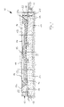
- Figure 1 comprises a track system 10 for a two-track Railroad track a massive supporting body 20, the one supported on a substructure or the ground 11 massive support plate 21 and attached, lateral, includes upwardly projecting edge caps 22.
- the Have top and bottom of the support plate 21 starting from the median longitudinal plane on both sides descending bank slope of 1:20, so that a so-called roof-shaped structure is reached.
- the edge caps 22 stand with a projection in a rectangular groove 19 Support plate 21 in engagement, so that a positive Connection is reached.
- the edge cap 22 also by means of a dowel 23 on the Support plate 21 may be attached.
- the support plate 21 forms together with the edge caps 22 a trough-shaped or gutter-shaped receptacle for a ballast bed 15.
- a sub-ballast mat 16 is inserted in the trough-shaped receptacle.
- the ballast bed 15 is possibly to form a stable in itself Ballast body glued and stores sleepers 13 as well Rails 14 in a known manner.
- the track can and thus the ballast bed especially when curved
- the route has a bank. In this case can use the corresponding edge cap to support the ballast bed also be elevated on the elevated side.
- a transverse drain channel 18 is formed, that reliably ensures drainage.
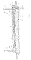
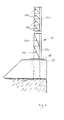
- the track system according to Figure 2 corresponds in all essentials Points of the track system according to Figure 1, however here additionally provided that on the essentially flat top 22b of the edge cap 22 a soundproof wall 25 is arranged and attached.
- a soundproof wall 25 is arranged and attached.
- the illustration on the left in FIG. 2 is Soundproof wall 25 in the opposite of the embodiment anchored widened edge cap 22 according to FIG. 1, while according to the illustration on the right Figure 2 laterally on the outside of the edge cap 22
- Foundation beam 12 is attached in which a foundation quiver 26 to accommodate soundproof wall cassettes or -panels is provided, optionally with a through the deep foundation 27 leading through the support plate 21 can be used.
- FIG 7 is an embodiment of an effective Soundproof wall 25 shown in steel.
- the soundproof wall 25 consists of one to be fastened Individual panels 25a and 25b, the lower one Panels 25a over a base plate 28 on the edge cap 22 attached or by supports in the quiver foundations is held.
- the panels 25a and 25b each have several inclined ones Reflection surfaces 28a and 28b, the surface normal in the is essentially directed to the ballast bed.
- the of the sound source wheel-rail outgoing sound waves are reflected by the reflection surfaces 28a and 28b in the Reflected area of the absorbent ballast bed.
- the upper panels 25b have four smaller ones inclined reflection surfaces 28b, while the lower Panels 25a has two larger reflection surfaces 25a, the reflective surfaces 28a of the lower panels 25a less inclination than the reflective surfaces 28b of FIG have upper panels 25b to in this way Adaptation to the different angles of incidence of sound waves emanating from the wheel-rail sound source to reach the soundproof wall 25.
- the support plate 21 as a continuous band-like concrete component is formed the surface of which recesses 24 are provided serve as transverse cable ducts, which by means of a cover can be closed.
- the edge caps 22 are made of precast concrete, lengthways the track system lined up and arranged a compensation layer 29 arranged on the support plate 21 are. In the joint area between two prefabricated edge caps are formed recesses that the transverse Form drainage channels 18.
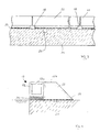
- FIG. 4 shows a first exemplary embodiment of an in Cable duct 17 running in the longitudinal direction of the track system.
- the edge cap 22 with arrangement of the compensation layer 29 on the support plate 21 attached so that between the laterally outer Wall of the support plate 21 and the laterally outer wall of the Edge cap 22 formed an inwardly facing gradation on which the cable duct 17 is interposed a compensation layer 30 is arranged.
- the cable duct 17 consists in a known manner of an open top U-shaped channel body 17a by means of a cover 17b is closable.
- the cable duct 17 cannot in in more detail on the support plate 21 or the Edge cap 22 may be attached.
- When assembled closes the outside of the cable duct 17 flush with the Outside of the support plate 21.
- the Lid 17b flush with the top 22b of the edge cap 22 about.
- the U-shaped channel body of the Cable duct 17 formed in one piece with the edge cap 22, again a cable duct 17 covering it Cover 17b is provided, the surface of which is flush with the top 22b of the edge cap 22 closes.
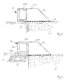
- FIG. 6 is on the edge cap 22 to the outside protruding cantilever 22c molded onto which the U-shaped Channel body 17a of the cable duct 17 placed and in is not shown attached.
- the gutter body 17a can be closed with the lid 17b, the Top of the lid 17b with the top 22b of the Edge cap 22 is flush.
- dashed in Fig. 6 can at the free end of the cantilever 22c the projection 22d engaging behind the channel body 17a be provided, whereby the channel body 17a in the transverse direction is kept safe.
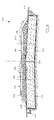
- the track system 110 shown in FIG. 8 comprises one double-track railway line with a solid support plate 120 in the form of a mass body on a substructure or the ground 111 is supported.
- the top and Bottom of the mass body 120 have, starting from the longitudinal median plane a sloping on both sides Bank of 1:20, so that a roof-shaped structure is reached.
- the mass body 120 is interposed an insulation mat 116 on its lower and its lateral surfaces completely in the ground 111 embedded. Run laterally along the mass body 120 Cable channels 117 in a known manner.
- ballast bed 118 On the top of the mass body 120 is interposed a ballast bed 118 a ballast bed 115 trained in a known manner, the swelling 113 and rails 114 for a two-lane route wearing.
- the course of the Ballast bed 115 for a straight section of the route shown while dashed the course of the ballast bed indicated for a curved route is.
- the thickness of the mass body 120 which is preferably the Formation protection layer and the frost protection layer replaced, is from the locally prevailing soil conditions and the relevant excitation frequencies and should be around one meter. Like figure 8 shows, the mass body 120 is laterally over the ballast bed 115 led out, so that from the train to the emitted pulses acting as a spring ballast bed completely into the mass body and from there after Attenuation can be transmitted to the ground.
Landscapes
- Engineering & Computer Science (AREA)
- Architecture (AREA)
- Civil Engineering (AREA)
- Structural Engineering (AREA)
- Life Sciences & Earth Sciences (AREA)
- Sustainable Development (AREA)
- Railway Tracks (AREA)
- Train Traffic Observation, Control, And Security (AREA)
- Machines For Laying And Maintaining Railways (AREA)
- Fittings On The Vehicle Exterior For Carrying Loads, And Devices For Holding Or Mounting Articles (AREA)
- Platform Screen Doors And Railroad Systems (AREA)
Description
- Figur 1:
- den Querschnitt einer Gleisanlage,
- Figur 2:
- einen Querschnitt einer modifizierten Gleisanlage,
- Figur 3:
- eine ausschnittsweise Seitenansicht einer Gleisanlage,
- Figur 4:
- eine erste Ausführungsform für einen Kabelkanal,
- Figur 5:
- eine zweite Ausführungsform für einen Kabelkanal,
- Figur 6:
- eine dritte Ausführungsform für einen Kabelkanal,
- Figur 7:
- ein Ausführungsbeispiel für eine Schallschutzwand und
- Figur 8:
- einen erfindungsgemäßen Massekörper.
Claims (20)
- Gleisanlage für schienengebundene Fahrzeuge, insbesondere Eisenbahnen, mit einem Oberbau, der auf Schwellen (13, 113) gelagerte Schienen (14, 114) und ein die Schwellen (13, 113) unterstützendes Schotterbett (15, 115) aufweist, und mit einem den Oberbau tragenden Unterbau, der eine das Schotterbett (15, 115) tragende Tragplatte (21, 120) aus Beton aufweist, die auf einem Erdbauwerk aufgelagert ist, dadurch gekennzeichnet, daß die Tragplatte (21, 120) als kontinuierliches, in Ortbeton hergestelltes Band ausgebildet ist und eine Stärke von mindestens 0,4 m aufweist.
- Gleisanlage nach Anspruch 1, dadurch gekennzeichnet, daß die Tragplatte (21, 120) eine Stärke im Bereich von 0,4 m bis 1,4 m, vorzugsweise von 0,7 m besitzt.
- Gleisanlage nach Anspruch 1 oder 2, dadurch gekennzeichnet, daß auf der Tragplatte (21) außenseitige, nach oben vorstehende Randkappen (22) angeordnet sind, die mit der Tragplatte (21) einen das Schotterbett aufnehmenden rinnenförmigen Tragkörper (20) bilden.
- Gleisanlage nach einem der Ansprüche 1 bis 3, dadurch gekennzeichnet, daß zwei Gleise vorgesehen sind und daß auf der Oberseite der Tragplatte zwischen den Gleisen eine nach oben vorstehende Mittelkappe angeordnet ist.
- Gleisanlage nach Anspruch 3 oder 4, dadurch gekennzeichnet, daß die Randkappen (22) und/oder die Mittelkappe aus Beton bestehen.
- Gleisanlage nach einem der Ansprüche 3 bis 5, dadurch gekennzeichnet, daß die Randkappen (22) und/ oder die Mittelkappe an die Tragplatte (21) angeformt sind.
- Gleisanlage nach einem der Ansprüche 3 bis 5, dadurch gekennzeichnet, daß die Randkappen (22) und/ oder die Mittelkappe als separate Bauteile ausgebildet und an der Tragplatte (21) befestigt sind.
- Gleisanlage nach einem der Ansprüche 3 bis 7, dadurch gekennzeichnet, daß die innere Wandung (22a) der Randkappen (22) und/oder der Mittelkappe derart geneigt ist, daß sie einen sich zum freien Ende hin verjüngenden Querschnitt besitzen.
- Gleisanlage nach einem der Ansprüche 1 bis 8, dadurch gekennzeichnet, daß das Schotterbett (15, 115) in sich zumindest teilweise verklebt ist.
- Gleisanlage nach einem der Ansprüche 1 bis 9, dadurch gekennzeichnet, daß zumindest die Oberseite der Tragplatte (21, 120) eine Querneigung besitzt.
- Gleisanlage nach Anspruch 10, dadurch gekennzeichnet, daß die Oberseite der Tragplatte (21, 120) ausgehend von deren Längsmittelachse zu beiden Seiten eine abfallende Querneigung besitzt.
- Gleisanlage nach Anspruch 10 oder 11, dadurch gekennzeichnet, daß die Querneigung etwa 1:20 beträgt.
- Gleisanlage nach einem der Ansprüche 1 bis 12, dadurch gekennzeichnet, daß zwischen dem Schotterbett (15, 115) und der Tragplatte (21, 120) eine Unterschottermatte (16, 116) angeordnet ist.
- Gleisanlage nach einem der Ansprüche 1 bis 13, dadurch gekennzeichnet, daß auf der im wesentlichen ebenen Oberseite (22b) der Randkappen (22) und/oder der Mittelkappe eine Schallschutzwand (25) angeordnet ist.
- Gleisanlage nach Anspruch 14, dadurch gekennzeichnet, daß die Schallschutzwand (25) auf der dem Gleis zugewandten Seite geneigte, die Schallwellen auf das Schotterbett (15) richtende Reflexionsflächen (28a, 28b) besitzt.
- Gleisanlage nach Anspruch 15, dadurch gekennzeichnet, daß die Reflexionsflächen (28a, 28b) unterschiedliche Neigungen besitzen.
- Gleisanlage nach einem der Ansprüche 1 bis 16, dadurch gekennzeichnet, daß in den Randkappen (22) und/oder der Mittelkappe quer verlaufende Abflußkanäle (18) ausgebildet sind.
- Gleisanlage nach einem der Ansprüche 1 bis 17, dadurch gekennzeichnet, daß in der Tragplatte (21, 120) quer verlaufende Kabelkanäle (24) ausgebildet sind.
- Gleisanlage nach einem der Ansprüche 1 bis 18, dadurch gekennzeichnet, daß an den Randkappen (22) und/oder der Mittelkappe in Längsrichtung verlaufende Kabelkanäle (17) vorgesehen sind.
- Gleisanlage nach Anspruch 19, dadurch gekennzeichnet, daß die Kabelkanäle (17) in die Randkappen (22) und/oder die Mittelkappe integriert sind.
Priority Applications (1)
| Application Number | Priority Date | Filing Date | Title |
|---|---|---|---|
| DE29622835U DE29622835U1 (de) | 1995-01-10 | 1996-01-09 | Gleisanlage für schienengebundene Fahrzeuge |
Applications Claiming Priority (2)
| Application Number | Priority Date | Filing Date | Title |
|---|---|---|---|
| DE19500443A DE19500443A1 (de) | 1995-01-10 | 1995-01-10 | Gleisanlage für schienengebundene Fahrzeuge |
| DE19500443 | 1995-01-10 |
Publications (2)
| Publication Number | Publication Date |
|---|---|
| EP0722012A1 EP0722012A1 (de) | 1996-07-17 |
| EP0722012B1 true EP0722012B1 (de) | 1998-04-29 |
Family
ID=7751180
Family Applications (1)
| Application Number | Title | Priority Date | Filing Date |
|---|---|---|---|
| EP96100188A Expired - Lifetime EP0722012B1 (de) | 1995-01-10 | 1996-01-09 | Gleisanlage für schienengebundene Fahrzeuge |
Country Status (4)
| Country | Link |
|---|---|
| EP (1) | EP0722012B1 (de) |
| AT (1) | ATE165637T1 (de) |
| DE (2) | DE19500443A1 (de) |
| DK (1) | DK0722012T3 (de) |
Cited By (5)
| Publication number | Priority date | Publication date | Assignee | Title |
|---|---|---|---|---|
| DE19831404C2 (de) * | 1998-07-15 | 2001-10-11 | Vogel Bau Gmbh | Gleisanlage für schienengebundene Fahrzeuge |
| DE102004002862A1 (de) * | 2004-01-19 | 2005-08-25 | Edilon Gmbh | Lärmarmer Gleiskörper |
| DE102008002836A1 (de) | 2008-04-30 | 2009-11-05 | Msb-Management Gmbh | Niedrige Lärmschutzwand an Gleisen |
| CN102787532A (zh) * | 2012-09-02 | 2012-11-21 | 中铁二院工程集团有限责任公司 | 高速铁路路肩及排水构造 |
| CN105735055A (zh) * | 2016-02-04 | 2016-07-06 | 李谨武 | 渗吸排水法 |
Families Citing this family (13)
| Publication number | Priority date | Publication date | Assignee | Title |
|---|---|---|---|---|
| DE19741020A1 (de) | 1997-09-18 | 1999-04-08 | Georg Groetz | Gleisanlage für schienengebundene Fahrzeuge |
| DE19841831A1 (de) * | 1998-09-12 | 2000-05-04 | Vogel Bau Gmbh | Gleisanlage für schienengebundene Fahrzeuge |
| DE20005558U1 (de) | 2000-03-24 | 2000-05-25 | Grötz, Georg, 76597 Loffenau | Gleisanlage für schienengebundene Fahrzeuge |
| FR2833023B1 (fr) * | 2001-12-05 | 2004-05-21 | Alstom | Procede de construction d'une voie ferree dans lequel on realise une dalle de voie en beton et on insere dans la dalle de voie des elements d'ancrage de la voie ferree |
| DE20120610U1 (de) | 2001-12-20 | 2002-02-28 | Grötz, Georg, 76597 Loffenau | Gleisschotter für ein Schotterbett eines Gleisfahrweges, insbesondere für Eisenbahnen |
| DE102008044675B4 (de) | 2008-08-28 | 2017-02-23 | Johann Walthelm Gmbh | Erschütterungsschutz für einen Gleisoberbau und Herstellungsverfahren dafür |
| AT512523B1 (de) * | 2011-11-22 | 2013-09-15 | Art Asamer Rubber Technology Gmbh | Fundamentlose Lärmschutzvorrichtung |
| DE102012105983A1 (de) * | 2012-07-04 | 2014-01-09 | Hering Bau Gmbh & Co. Kg | Akustische Abschirmeinheit und deren Aufbau |
| AT514307B1 (de) * | 2013-05-02 | 2016-08-15 | Kossik Roman | Auflager für Massivelemente in Fahrwegen mit Schotteroberbau auf elastischer, bituminös- gebundener Tragschicht |
| HUP1300644A2 (en) * | 2013-11-08 | 2015-05-28 | Jozsef Szabo | Structural arrangement and method for stabilizing earthworks and formations |
| CN108842522B (zh) * | 2018-06-06 | 2023-11-24 | 广州地铁设计研究院股份有限公司 | 一种可调减振等级的预制浮置板轨道 |
| CN110761127B (zh) * | 2019-12-04 | 2024-10-15 | 中铁二院工程集团有限责任公司 | 一种岩石地基既有高铁路堤力平衡帮宽结构及构筑方法 |
| CN113062148B (zh) * | 2021-03-30 | 2022-05-13 | 武汉理工大学 | 一种高速铁路基床表层厚度灵活性设计方法 |
Family Cites Families (7)
| Publication number | Priority date | Publication date | Assignee | Title |
|---|---|---|---|---|
| US1633211A (en) * | 1924-06-30 | 1927-06-21 | Edwin A Jenks | Roadway embankment |
| DE1243225B (de) * | 1964-05-21 | 1967-06-29 | Gruenzweig & Hartmann | Schall- und schwingungsisolierende Schotterbettlagerung |
| US3587964A (en) * | 1969-04-18 | 1971-06-28 | Meadows W R Inc | Protective course for bridge deck |
| DE2751346C2 (de) * | 1977-11-17 | 1983-12-22 | Phoenix Ag, 2100 Hamburg | Isoliermatte für Gleisanlagen |
| DE4007710C2 (de) * | 1990-03-10 | 1995-04-06 | Dyckerhoff & Widmann Ag | Verfahren zum Herstellen eines Eisenbahnoberbaus im Tunnel |
| DE4100881A1 (de) * | 1991-01-14 | 1992-07-16 | Cronau Heinrich Gmbh | Oberbau fuer eisenbahn-gleisanlagen |
| DE4401260C1 (de) * | 1994-01-18 | 1995-05-18 | Heitkamp Gmbh Bau | Oberbau für Eisenbahngleise |
-
1995
- 1995-01-10 DE DE19500443A patent/DE19500443A1/de not_active Ceased
-
1996
- 1996-01-09 EP EP96100188A patent/EP0722012B1/de not_active Expired - Lifetime
- 1996-01-09 AT AT96100188T patent/ATE165637T1/de not_active IP Right Cessation
- 1996-01-09 DE DE59600164T patent/DE59600164D1/de not_active Expired - Lifetime
- 1996-01-09 DK DK96100188T patent/DK0722012T3/da active
Cited By (6)
| Publication number | Priority date | Publication date | Assignee | Title |
|---|---|---|---|---|
| DE19831404C2 (de) * | 1998-07-15 | 2001-10-11 | Vogel Bau Gmbh | Gleisanlage für schienengebundene Fahrzeuge |
| DE102004002862A1 (de) * | 2004-01-19 | 2005-08-25 | Edilon Gmbh | Lärmarmer Gleiskörper |
| DE102008002836A1 (de) | 2008-04-30 | 2009-11-05 | Msb-Management Gmbh | Niedrige Lärmschutzwand an Gleisen |
| CN102787532A (zh) * | 2012-09-02 | 2012-11-21 | 中铁二院工程集团有限责任公司 | 高速铁路路肩及排水构造 |
| CN105735055A (zh) * | 2016-02-04 | 2016-07-06 | 李谨武 | 渗吸排水法 |
| CN105735055B (zh) * | 2016-02-04 | 2018-05-04 | 陈森 | 渗吸排水法 |
Also Published As
| Publication number | Publication date |
|---|---|
| EP0722012A1 (de) | 1996-07-17 |
| ATE165637T1 (de) | 1998-05-15 |
| DE19500443A1 (de) | 1996-07-18 |
| DE59600164D1 (de) | 1998-06-04 |
| DK0722012T3 (da) | 1999-02-15 |
Similar Documents
| Publication | Publication Date | Title |
|---|---|---|
| EP0722012B1 (de) | Gleisanlage für schienengebundene Fahrzeuge | |
| EP0937181B1 (de) | Unterbau für ein gleis für schienenfahrzeuge | |
| DE102008002836A1 (de) | Niedrige Lärmschutzwand an Gleisen | |
| DE4100881A1 (de) | Oberbau fuer eisenbahn-gleisanlagen | |
| DE19503220A1 (de) | System für den schotterlosen Oberbau von Gleisanlagen | |
| EP2210978A2 (de) | Minischutzwand für Schwellengleise | |
| WO2009121323A1 (de) | Feste fahrbahn für schienenfahrzeuge | |
| DE29810176U1 (de) | Tunnelfahrweg | |
| EP0547082B1 (de) | Unterbau für ein gleis für schienenfahrzeuge | |
| DE102007037339B4 (de) | Gabionenwand mit lärmdämmender, monolithischer Schicht aus Beton | |
| EP1825059B1 (de) | Betonfahrbahn für schienenfahrzeuge | |
| AT512523B1 (de) | Fundamentlose Lärmschutzvorrichtung | |
| DE19706708C2 (de) | Vorrichtung zur Schalldämpfung einer festen Fahrbahn | |
| DE102006013851A1 (de) | Schottertragschicht auf tiefliegender Elastomerschicht | |
| AT370461B (de) | Verfahren zum herstellen eines elastisch gelagerten troges aus stahlbeton als koerperschalldaemmende tragkonstruktion fuer den oberbau einer schienenbahn, insbesondere auf innerstaedtischen tunnelstrecken | |
| DE29622835U1 (de) | Gleisanlage für schienengebundene Fahrzeuge | |
| DE60106552T2 (de) | Gleis für ein schienengebundenes Fahrzeug und eine ein derartiges Gleis enthaltende Einrichtung | |
| EP0968330B1 (de) | Aufgeständerte Fahrbahnplattenvorrichtung | |
| DE8911400U1 (de) | Schotterloser Oberbau aus Fertigteilen | |
| DE102004002862A1 (de) | Lärmarmer Gleiskörper | |
| DE19831404C2 (de) | Gleisanlage für schienengebundene Fahrzeuge | |
| DE19706542B4 (de) | Fahrbahn | |
| DE20216387U1 (de) | Gleisanlage für schienengebundene Fahrzeuge | |
| DE19625249A1 (de) | Lagestabiles Gleis aus Betonfertigteilen | |
| DE19841831A1 (de) | Gleisanlage für schienengebundene Fahrzeuge |
Legal Events
| Date | Code | Title | Description |
|---|---|---|---|
| PUAI | Public reference made under article 153(3) epc to a published international application that has entered the european phase |
Free format text: ORIGINAL CODE: 0009012 |
|
| AK | Designated contracting states |
Kind code of ref document: A1 Designated state(s): AT BE CH DE DK FR IT LI LU NL |
|
| 17P | Request for examination filed |
Effective date: 19960725 |
|
| GRAG | Despatch of communication of intention to grant |
Free format text: ORIGINAL CODE: EPIDOS AGRA |
|
| GRAG | Despatch of communication of intention to grant |
Free format text: ORIGINAL CODE: EPIDOS AGRA |
|
| GRAH | Despatch of communication of intention to grant a patent |
Free format text: ORIGINAL CODE: EPIDOS IGRA |
|
| 17Q | First examination report despatched |
Effective date: 19971017 |
|
| GRAH | Despatch of communication of intention to grant a patent |
Free format text: ORIGINAL CODE: EPIDOS IGRA |
|
| GRAA | (expected) grant |
Free format text: ORIGINAL CODE: 0009210 |
|
| AK | Designated contracting states |
Kind code of ref document: B1 Designated state(s): AT BE CH DE DK FR IT LI LU NL |
|
| REF | Corresponds to: |
Ref document number: 165637 Country of ref document: AT Date of ref document: 19980515 Kind code of ref document: T |
|
| REG | Reference to a national code |
Ref country code: CH Ref legal event code: EP |
|
| ITF | It: translation for a ep patent filed | ||
| REF | Corresponds to: |
Ref document number: 59600164 Country of ref document: DE Date of ref document: 19980604 |
|
| REG | Reference to a national code |
Ref country code: CH Ref legal event code: NV Representative=s name: TROESCH SCHEIDEGGER WERNER AG |
|
| ET | Fr: translation filed | ||
| PLBQ | Unpublished change to opponent data |
Free format text: ORIGINAL CODE: EPIDOS OPPO |
|
| PLBI | Opposition filed |
Free format text: ORIGINAL CODE: 0009260 |
|
| REG | Reference to a national code |
Ref country code: DK Ref legal event code: T3 |
|
| PLBF | Reply of patent proprietor to notice(s) of opposition |
Free format text: ORIGINAL CODE: EPIDOS OBSO |
|
| 26 | Opposition filed |
Opponent name: SCHWEIZ. BUNDESBAHNEN SBB Effective date: 19990128 |
|
| NLR1 | Nl: opposition has been filed with the epo |
Opponent name: SCHWEIZ. BUNDESBAHNEN SBBB AUDIREKTION |
|
| PLBF | Reply of patent proprietor to notice(s) of opposition |
Free format text: ORIGINAL CODE: EPIDOS OBSO |
|
| PLBF | Reply of patent proprietor to notice(s) of opposition |
Free format text: ORIGINAL CODE: EPIDOS OBSO |
|
| PLBL | Opposition procedure terminated |
Free format text: ORIGINAL CODE: EPIDOS OPPC |
|
| PLBM | Termination of opposition procedure: date of legal effect published |
Free format text: ORIGINAL CODE: 0009276 |
|
| STAA | Information on the status of an ep patent application or granted ep patent |
Free format text: STATUS: OPPOSITION PROCEDURE CLOSED |
|
| 27C | Opposition proceedings terminated |
Effective date: 20000102 |
|
| NLR2 | Nl: decision of opposition | ||
| PGFP | Annual fee paid to national office [announced via postgrant information from national office to epo] |
Ref country code: AT Payment date: 20060113 Year of fee payment: 11 |
|
| PGFP | Annual fee paid to national office [announced via postgrant information from national office to epo] |
Ref country code: NL Payment date: 20060119 Year of fee payment: 11 |
|
| PGFP | Annual fee paid to national office [announced via postgrant information from national office to epo] |
Ref country code: DK Payment date: 20060125 Year of fee payment: 11 Ref country code: BE Payment date: 20060125 Year of fee payment: 11 |
|
| PGFP | Annual fee paid to national office [announced via postgrant information from national office to epo] |
Ref country code: LU Payment date: 20060203 Year of fee payment: 11 |
|
| PGFP | Annual fee paid to national office [announced via postgrant information from national office to epo] |
Ref country code: CH Payment date: 20060327 Year of fee payment: 11 |
|
| PG25 | Lapsed in a contracting state [announced via postgrant information from national office to epo] |
Ref country code: LI Free format text: LAPSE BECAUSE OF NON-PAYMENT OF DUE FEES Effective date: 20070131 Ref country code: CH Free format text: LAPSE BECAUSE OF NON-PAYMENT OF DUE FEES Effective date: 20070131 |
|
| REG | Reference to a national code |
Ref country code: CH Ref legal event code: PL |
|
| NLV4 | Nl: lapsed or anulled due to non-payment of the annual fee |
Effective date: 20070801 |
|
| REG | Reference to a national code |
Ref country code: DK Ref legal event code: EBP |
|
| PG25 | Lapsed in a contracting state [announced via postgrant information from national office to epo] |
Ref country code: AT Free format text: LAPSE BECAUSE OF NON-PAYMENT OF DUE FEES Effective date: 20070109 |
|
| BERE | Be: lapsed |
Owner name: *GROTZ GEORG Effective date: 20070131 |
|
| PG25 | Lapsed in a contracting state [announced via postgrant information from national office to epo] |
Ref country code: BE Free format text: LAPSE BECAUSE OF NON-PAYMENT OF DUE FEES Effective date: 20070131 |
|
| PG25 | Lapsed in a contracting state [announced via postgrant information from national office to epo] |
Ref country code: NL Free format text: LAPSE BECAUSE OF NON-PAYMENT OF DUE FEES Effective date: 20070801 Ref country code: DK Free format text: LAPSE BECAUSE OF NON-PAYMENT OF DUE FEES Effective date: 20070131 |
|
| PG25 | Lapsed in a contracting state [announced via postgrant information from national office to epo] |
Ref country code: LU Free format text: LAPSE BECAUSE OF NON-PAYMENT OF DUE FEES Effective date: 20070109 |
|
| PGFP | Annual fee paid to national office [announced via postgrant information from national office to epo] |
Ref country code: IT Payment date: 20110126 Year of fee payment: 16 Ref country code: FR Payment date: 20110209 Year of fee payment: 16 |
|
| REG | Reference to a national code |
Ref country code: FR Ref legal event code: ST Effective date: 20120928 |
|
| PG25 | Lapsed in a contracting state [announced via postgrant information from national office to epo] |
Ref country code: IT Free format text: LAPSE BECAUSE OF NON-PAYMENT OF DUE FEES Effective date: 20120109 |
|
| PG25 | Lapsed in a contracting state [announced via postgrant information from national office to epo] |
Ref country code: FR Free format text: LAPSE BECAUSE OF NON-PAYMENT OF DUE FEES Effective date: 20120131 |
|
| PGFP | Annual fee paid to national office [announced via postgrant information from national office to epo] |
Ref country code: DE Payment date: 20150124 Year of fee payment: 20 |
|
| REG | Reference to a national code |
Ref country code: DE Ref legal event code: R071 Ref document number: 59600164 Country of ref document: DE |