EP0720520B1 - Abrasive article, method of manufacture of same, method of using same for finishing, and a production tool - Google Patents
Abrasive article, method of manufacture of same, method of using same for finishing, and a production tool Download PDFInfo
- Publication number
- EP0720520B1 EP0720520B1 EP94908617A EP94908617A EP0720520B1 EP 0720520 B1 EP0720520 B1 EP 0720520B1 EP 94908617 A EP94908617 A EP 94908617A EP 94908617 A EP94908617 A EP 94908617A EP 0720520 B1 EP0720520 B1 EP 0720520B1
- Authority
- EP
- European Patent Office
- Prior art keywords
- abrasive
- composites
- composite
- abrasive article
- production tool
- Prior art date
- Legal status (The legal status is an assumption and is not a legal conclusion. Google has not performed a legal analysis and makes no representation as to the accuracy of the status listed.)
- Expired - Lifetime
Links
Images
Classifications
-
- B—PERFORMING OPERATIONS; TRANSPORTING
- B24—GRINDING; POLISHING
- B24D—TOOLS FOR GRINDING, BUFFING OR SHARPENING
- B24D3/00—Physical features of abrasive bodies, or sheets, e.g. abrasive surfaces of special nature; Abrasive bodies or sheets characterised by their constituents
- B24D3/02—Physical features of abrasive bodies, or sheets, e.g. abrasive surfaces of special nature; Abrasive bodies or sheets characterised by their constituents the constituent being used as bonding agent
- B24D3/20—Physical features of abrasive bodies, or sheets, e.g. abrasive surfaces of special nature; Abrasive bodies or sheets characterised by their constituents the constituent being used as bonding agent and being essentially organic
- B24D3/28—Resins or natural or synthetic macromolecular compounds
-
- B—PERFORMING OPERATIONS; TRANSPORTING
- B24—GRINDING; POLISHING
- B24D—TOOLS FOR GRINDING, BUFFING OR SHARPENING
- B24D11/00—Constructional features of flexible abrasive materials; Special features in the manufacture of such materials
-
- B—PERFORMING OPERATIONS; TRANSPORTING
- B24—GRINDING; POLISHING
- B24D—TOOLS FOR GRINDING, BUFFING OR SHARPENING
- B24D11/00—Constructional features of flexible abrasive materials; Special features in the manufacture of such materials
- B24D11/001—Manufacture of flexible abrasive materials
- B24D11/005—Making abrasive webs
-
- B—PERFORMING OPERATIONS; TRANSPORTING
- B24—GRINDING; POLISHING
- B24D—TOOLS FOR GRINDING, BUFFING OR SHARPENING
- B24D18/00—Manufacture of grinding tools or other grinding devices, e.g. wheels, not otherwise provided for
-
- Y—GENERAL TAGGING OF NEW TECHNOLOGICAL DEVELOPMENTS; GENERAL TAGGING OF CROSS-SECTIONAL TECHNOLOGIES SPANNING OVER SEVERAL SECTIONS OF THE IPC; TECHNICAL SUBJECTS COVERED BY FORMER USPC CROSS-REFERENCE ART COLLECTIONS [XRACs] AND DIGESTS
- Y10—TECHNICAL SUBJECTS COVERED BY FORMER USPC
- Y10T—TECHNICAL SUBJECTS COVERED BY FORMER US CLASSIFICATION
- Y10T29/00—Metal working
- Y10T29/49—Method of mechanical manufacture
- Y10T29/4998—Combined manufacture including applying or shaping of fluent material
-
- Y—GENERAL TAGGING OF NEW TECHNOLOGICAL DEVELOPMENTS; GENERAL TAGGING OF CROSS-SECTIONAL TECHNOLOGIES SPANNING OVER SEVERAL SECTIONS OF THE IPC; TECHNICAL SUBJECTS COVERED BY FORMER USPC CROSS-REFERENCE ART COLLECTIONS [XRACs] AND DIGESTS
- Y10—TECHNICAL SUBJECTS COVERED BY FORMER USPC
- Y10T—TECHNICAL SUBJECTS COVERED BY FORMER US CLASSIFICATION
- Y10T29/00—Metal working
- Y10T29/49—Method of mechanical manufacture
- Y10T29/49995—Shaping one-piece blank by removing material
-
- Y—GENERAL TAGGING OF NEW TECHNOLOGICAL DEVELOPMENTS; GENERAL TAGGING OF CROSS-SECTIONAL TECHNOLOGIES SPANNING OVER SEVERAL SECTIONS OF THE IPC; TECHNICAL SUBJECTS COVERED BY FORMER USPC CROSS-REFERENCE ART COLLECTIONS [XRACs] AND DIGESTS
- Y10—TECHNICAL SUBJECTS COVERED BY FORMER USPC
- Y10T—TECHNICAL SUBJECTS COVERED BY FORMER US CLASSIFICATION
- Y10T83/00—Cutting
- Y10T83/04—Processes
- Y10T83/05—With reorientation of tool between cuts
Definitions
- This invention relates to an abrasive article having a sheet-like structure having a major surface having deployed thereon a plurality of abrasive composites having precise shapes, wherein the precise shapes are not all identical.
- the invention also relates to methods of manufacturing an abrasive article, and a production tool used to manufacture such an abrasive article, and a method of using such an abrasive article to reduce a surface finish.
- abrasive articles employ a plurality of abrasive particles which are bonded together as a unitary structure (e.g., a grinding wheel) or bonded separately to a common backing (e.g., a coated abrasive article). While these types of abrasive articles have been utilized to abrade and finish workpieces for many years, problems remain in the field.
- one persistent problem confronting the abrasive industry arises from the generally inverse relationship associated between the cut rate (i.e., the amount of workpiece removed for a given time interval) and the finish that is imparted by the abrasive article on the workpiece surface. That is, it is difficult to design an abrasive article that affords a relatively high rate of cut while concomitantly imparting a relatively fine surface finish on the workpiece being abraded. This explains the presence of a wide range of abrasive products in the market using coarse grit (i.e., relatively large particle size of abrasive particles) to fine grit (i.e., relatively small particle size of abrasive particles).
- U.S. Patent No. 2,115,897 (Wooddell et al.) teaches an abrasive article having a backing and attached thereto by an adhesive are a plurality of blocks of bonded abrasive material. These bonded abrasive blocks can be adhesively secured to the backing in a specified pattern.
- U.S. Patent No. 2,755,607 (Haywood) teaches a coated abrasive in which there are land and groove abrasive portions, which can form, for example, an overall rectlinear or serpentine pattern.
- An adhesive coat is applied to the front surface of a backing and this adhesive coat is then combed to create peaks and valleys to pattern the surface of the adhesive coat.
- Haywood discloses that each of the lands and grooves formed in the adhesive coat by such a combing procedure preferably have the same width and thickness, but that they may be varied.
- the abrasive grains are distributed uniformly in the lands and grooves of the previously patterned adhesive coat followed by solidification of the adhesive coat.
- the abrasive particles used in Haywood are individual grains which are not used in slurry form with other grains in a binder. Therefore, the individual abrasive grains have irregular non-precise shapes.
- U.S. Patent No. 3,048,482 discloses an abrasive article comprising a backing, a bond system and abrasive granules that are secured to the backing by the bond system.
- the abrasive granules are a composite of abrasive grains and a binder which is separate from the bond system.
- the abrasive granules are three dimensional and are preferably pyramidal in shape.
- the abrasive granules are first made via a molding process. Next, a backing is placed in a mold, followed by the bond system and the abrasive granules. The mold has patternized cavities therein which results in the abrasive granules having a specified pattern on the backing.
- U.S. Patent No. 3,605,349 (Anthon) pertains to a lapping type abrasive article.
- the binder and the abrasive grain are mixed together and then sprayed onto the backing through a grid. The presence of the grid results in a patterned abrasive coating.
- Great Britain Patent Application No. 2,094,824 pertains to a patterned lapping film.
- the abrasive slurry is prepared and the slurry is applied through a mask to form discrete islands.
- the resin or binder is cured.
- the mask can be a silk screen, stencil, wire, or a mesh.
- U.S. Patent No. 4,930,266 (Calhoun et al.) teaches a patterned abrasive sheeting in which the abrasive granules are strongly bonded and lie substantially in a plane at a predetermined lateral spacing.
- the abrasive granules are applied via a impingement technique so that each granule is essentially individually applied to the abrasive backing. This results in an abrasive sheeting having a precisely controlled spacing of the abrasive granules.
- U.S. Patent No. 5,014,468 pertains to a lapping film intended for ophthalmic applications.
- the lapping film comprises a patterned surface coating of abrasive grains dispersed in a radiation cured adhesive binder.
- the patterned surface coating has a plurality of discrete raised three dimensional formations having widths which diminish in the direction away from the backing.
- an abrasive slurry is applied to a rotogravure roll to provide a shapes surface which is then removed from the roll surface and then the radiation curable resin is cured.
- U.S. Patent No. 5,015,266 (Yamamoto) pertains to an abrasive sheet by uniformly coating an abrasive adhesive slurry over an embossed sheet.
- the resulting abrasive coating has high and low abrasive portions formed by the surface tension of the slurry, corresponding to the irregularities of the base sheet.
- U.S. Patent No. 5,107,626 (Mucci) teaches a method of providing a patterned surface on a substrate by abrading with a coated abrasive containing a plurality of precisely shaped abrasive composites.
- the abrasive composites are in a non-random array and the abrasive composites comprise a plurality of abrasive grains dispersed in a binder.
- U.S. Patent No. 5,152,917 discloses a coated abrasive article that provides both a relatively high rate of cut and a relatively fine surface finish on the workpiece surface.
- the structured abrasive of Pieper et al. involves precisely shaped abrasive composites that are bonded to a backing in a regular nonrandom pattern.
- the consistency of the profile of the abrasive composites provided by the abrasive strucutre of Pieper et al. helps provide a consistent surface finish in the worked surface.
- Japanese Patent Application No. S63-235942 published March 23, 1990 teaches a method of a making a lapping film having a specified pattern.
- An abrasive slurry is coated into a network of indentations in a tool.
- a backing is then applied over the tool and the binder in the abrasive slurry is cured.
- the resulting coated abrasive is removed from the tool.
- the binder can be cured by radiation energy or thermal energy.
- Japanese Patent Application No. JP 4-159084 published June 2, 1992 teaches a method of making a lapping tape.
- An abrasive slurry comprising abrasive grains and an electron beam curable resin is applied to the surface of an intaglio roll or indentation plate having a network of indentations. Then, the abrasive slurry is exposed to an electron beam which cures the binder and the resulting lapping tape is removed from the roll.
- U.S. Patent No. 5,219,462 (Bruxvoort et al.) teaches a method for making an abrasive article.
- An abrasive slurry is coated substantially only into the recesses of an embossed backing.
- the abrasive slurry comprises a binder, abrasive grains and an expanding agent. After coating, the binder is cured and the expanding agent is activated. This causes the slurry to expand above the surface of the embossed backing.
- United States patent application No. 08/067,708 filed 26 May 1993 (Mucci et al.), which is commonly assigned to the owner of the present application, teaches a method of polishing a workpiece with a structured abrasive.
- the structured abrasive comprises a plurality of precisely shaped abrasive composites bonded to a backing. During polishing, the structured abrasive oscillates.
- variable pitch sawing teeth has been disclosed as a cutting edge for a hack saw blade, such as mentioned in a trade advertisement distributed by Lenox Co. and entitled "Lenox hackmaster V Vari-Tooth Power hack Saw Blades", to provide balanced cutting action and quiet performance.
- This hack saw blade design is described as useful to saw metal bar stock, ganged workpieces, or work with holes, slots or interruptions.
- This hack saw blade design is not specifically disclosed as adaptable for frictional abrasion applications between two rubbing surfaces including a complex three-dimensional working surface, nor does the LENOX publication disclose the wherewithal therefor.
- the present invention provides an abrasive article which has a high cut rate yet imparts a relatively fine surface finish.
- the invention provides an abrasive article having a sheet-like structure having a major surface having deployed thereon a plurality of precisely shaped abrasive composites, wherein not all shapes are identical.
- the invention also provides methods of manufacturing the abrasive article, a production tool useful in such methods, and a method of using the abrasive article to reduce surface finish.
- this invention relates to an abrasive article having a sheet-like structure having a major surface having deployed in fixed position thereon a plurality of three-dimensional abrasive composites, each of the composites comprising abrasive particles dispersed in a binder and having a substantially precise shape defined by a substantially distinct and discernible boundary which includes substantially specific dimensions, wherein the precise shapes are not all identical.
- This aspect of the invention is defined in claim 1.
- substantially all of the aforesaid abrasive composites exist as pairs, each pair including two unmatched abrasive composites, one abrasive composite having a nonidentical shape to an adjacent abrasive composite.
- the aforesaid first and second abrasive composites have a first and second geometrical shape, respectively, which are nonidentical.
- the aforesaid first and second geometrical shapes can be selected from different members of the group of geometrical shapes consisting of cubic, prismatic, conical, truncated conical, cylindrical, pyramidal, and truncated pyramidal.
- no angle of intersection of adjacent planar surfaces in the first abrasive composite is equal to 0° or 90°.
- substantially all the abrasive composites have a pyramidal shape.
- abrasive composites are fixed on the major surface in a density of about 100 to about 10,000 abrasive composites/cm 2 . In one further embodiment, substantially the entire surface area of the major surface is covered by the abrasive composites.
- the abrasive article defined in claim 1 is used in a method to reduce the surface of a workpiece, having the steps of:
- the invention relates to a production tool for making the aforesaid abrasive article, which tool is defined in claim 15.
- the right and left half angles of the projections formed in the master surface each have a value between 8° and 45° and the three-dimensional shapes comprise pyramids.
- the abrasive article of the invention exhibits a high rate of cut while imparting a relatively level, fine surface finish on the workpiece being abraded and does not readily scribe the workpiece. While not desiring to be bound to any theory at this time, it is hypothesized that an array of abrasive composites having perfect pitch, i.e., an array of abrasive composites that are all identical in dimensions, may generate a vibrational resonance, whereby the working abrasive article surface may reach a resonant vibration state which can cause surface finish problems, known as chatter marks.
- the expression "precisely-shaped", or the like, as used herein in describing the abrasive composites refers to abrasive composites having a shape that has been formed by curing the curable binder of a flowable mixture of abrasive particles and curable binder while the mixture is both being borne on a backing and filling a cavity on the surface of a production tool.
- Such a "precisly shaped" abrasive composite would thus have precisely the same shape as that of the cavity.
- the precise shape of the abrasive composite is defined by relatively smooth-surfaced sides that are bounded and joined by well-defined sharp edges having distinct edge lengths with distinct endpoints defined by the intersections of the various sides with the proviso that at least one of said abrasive composites has at least one dimension which is different from that of an adjacent abrasive composite or composites.
- the term "boundary”, as used herein to define the abrasive composites, means the exposed surfaces and edges of each abrasive composite that delimit and define the actual three-dimensional shape of each abrasive composite. These distinct and discernible boundaries are readily visible and clear when a cross-section of the abrasive article of the invention is examined under a microscope such as a scanning electron microscope.
- the distinct and discernible boundaries of each abrasive composite form the cross-sectional outlines and contours of the precise shapes of the present invention. These boundaries separate and distinguish one abrasive composite from another even when the abrasive composites abutt each other along a common border at their bases.
- the boundaries and edges are not definitive, e.g., where the abrasive composite sags before completion of its curing.
- the term "dimension”, as used in connection with defining the abrasive composites, means a measure of spatial extent such as an edge length of a side surface (inclusive of the base) of the shape associated with an abrasive composite or, alternatively, the "dimension” can mean a measure of an angle of inclination of a side surface extending from the backing.
- a "dimension” that is "different” for two different abrasive composites means an edge length or an angle of intersection made at the meeting edge of two planar surfaces of a shape of a first abrasive composite that is nowhere duplicated in value by any of the edge lengths or angles of intersections defining the shape of a second abrasive composite in the array.
- first and second abrasive composites can be adjacent in a preferred embodiment.
- geometrical shape means a basic category of three-dimensional regular geometrical shape, such as cubic, pyramidal, pyrismatic, conical, cylindrical, truncated pyramidal, truncated conical and the like.
- adjacent composite or “adjacent composites”, or the like, as used herein, means at least two neighboring composites which lack any intervening abrasive composite structure located on a direct line therebetween.
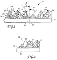
- the side view of the abrasive article 10 shows a backing 11 having a pair of opposite side edges 19 (one shown), a machine direction axis (not shown) would extend parallel to the direction of said side edges 19 for purposes of this illustration, and a plurality of abrasive composites 12 fixed to at least the top surface 16 of the backing.
- the abrasive composites 12 comprise a plurality of abrasive particles 13 dispersed in the binder 14.
- Each abrasive composite has a discernible precise shape. It is preferred that the abrasive particles do not protrude beyond the planar surface planes 15 of the shape before the coated abrasive article is put into service. As the coated abrasive article is being used to abrade a surface, the composite breaks down revealing unused abrasive particles.
- the "adjacent composite” will involve one nearest neighboring composite or multiple nearest neighboring composites equidistantly spaced from the abrasive composite which has the different dimension thereto.
- the abrasive composites are spaced at a varied pitch, then it is possible, in that instance, for the "adjacent composite" to involve an abrasive composite which is not necessarily the closest composite as spaced from the abrasive composite having the different dimension thereto, as long as no intervening abrasive structure is located on a direct line therebetween.
- a backing can be conveniently used in this invention to provide a surface for deploying the abrasive composites thereon, wherein such a backing has a front and back surface and can be any conventional abrasive backing. Examples of such include polymeric film, primed polymeric film, cloth, paper, vulcanized fiber, nonwovens, and combinations thereof.
- the backing optionally may be a reinforced thermoplastic backing, such as described in the assignee's co-pending United States application No. 07/811,547 (Stout et al., filed 20 December 1991) or an endless belt as described in the assignee's co-pending U.S. application No. 07/919,541 (Benedict et al., filed 20 December 1991).
- the backing may also contain a treatment or treatments to seal the backing and/or modify some physical properties of the backing. These treatments are well known in the art.
- the backing may also have an attachment means on its back surface to secure the resulting coated abrasive to a support pad or back-up pad.
- This attachment means can be a pressure sensitive adhesive or a loop fabric for a hook and loop attachment.
- the back side of the abrasive article may also contain a slip resistant or frictional coating.
- a slip resistant or frictional coating include compositions containing an inorganic particulate (e.g., calcium carbonate or quartz) dispersed in an adhesive.
- An antistatic coating comprising materials such as carbon black or vanadium oxide also may be included in the abrasive article, if desired.
- the abrasive particles typically have a particle size ranging from about 0.1 to 1500 micrometers, usually between about 0.1 to 400 micrometers, preferably between 0.1 to 100 micrometers and more preferably between 0.1 to 50 micrometers. It is preferred that the abrasive particles have a Mohs' hardness of at least about 8, more preferably above 9. Examples of such abrasive particles include fused aluminum oxide (which includes brown aluminum oxide, heat treated aluminum oxide, and white aluminum oxide), ceramic aluminum oxide, green silicon carbide, silicon carbide, chromia, alumina zirconia, diamond, iron oxide, ceria, cubic boron nitride, boron carbide, garnet, and combinations thereof.
- fused aluminum oxide which includes brown aluminum oxide, heat treated aluminum oxide, and white aluminum oxide
- ceramic aluminum oxide green silicon carbide, silicon carbide, chromia, alumina zirconia, diamond, iron oxide, ceria, cubic boron nitride, boron carbide, garne
- abrasive particles also encompasses when single abrasive particles are bonded together to form an abrasive agglomerate. Suitable abrasive agglomerates for this invention are further described in U.S. Patent Nos. 4,311,489 (Kressner); 4,652,275 (Bloecher et al.) and 4,799,939 (Bloecher et al.).
- the surface coating may have many different functions. In some instances the surface coatings increase adhesion to the binder, alter the abrading characteristics of the abrasive particle, and the like. Examples of surface coatings include coupling agents, halide salts, metal oxides including silica, refractory metal nitrides, refractory metal carbides, and the like.
- diluent particles In the abrasive composite there may also be diluent particles.
- the particle size of these diluent particles may be on the same order of magnitude as the abrasive particles. Examples of such diluent particles include gypsum, marble, limestone, flint, silica, glass bubbles, glass beads, aluminum silicate, and the like.
- the abrasive particles are dispersed in an organic binder to form the abrasive composite.
- the organic binder can be a thermoplastic binder, however, it is preferably a thermosetting binder.
- the binder is formed from a binder precursor. During the manufacture of the abrasive article, the thermosetting binder precursor is exposed to an energy source which aids in the initiation of the polymerization or curing process. Examples of energy sources include thermal energy and radiation energy which includes electron beam, ultraviolet light, and visible light. After this polymerization process, the binder precursor is converted into a solidified binder.
- the binder in the abrasive composite is generally also responsible for adhering the abrasive composite to the front surface of the backing. However, it some instances there may be an additional adhesive layer between the front surface of the backing and the abrasive composite.
- thermosetting resins there are two main classes of thermosetting resins, condensation curable and addition polymerized resins.
- the preferred binder precursors are addition polymerized resin because they are readily cured by exposure to radiation energy. Addition polymerized resins can polymerize through a cationic mechanism or a free radical mechanism. Depending upon the energy source that is utilized and the binder precursor chemistry, a curing agent, initiator, or catalyst is sometimes preferred to help initiate the polymerization.
- binders precursors examples include phenolic resins, urea-formaldehyde resins, melamine formaldehyde resins, acrylated urethanes, acrylated epoxies, ethylenically unsaturated compounds, aminoplast derivatives having pendant unsaturated carbonyl groups, isocyanurate derivatives having at least one pendant acrylate group, isocyanate derivatives having at least one pendant acrylate group, vinyl ethers, epoxy resins, and mixtures and combinations thereof.
- acrylate encompasses acrylates and methacrylates.
- Phenolic resins are widely used in abrasive article binders because of their thermal properties, availability, and cost. There are two types of phenolic resins, resole and novolac. Resole phenolic resins have a molar ratio of formaldehyde to phenol greater than or equal to one to one, typically between 1.5:1.0 to 3.0:1.0. Novolac resins have a molar ratio of formaldehyde to phenol of less than one to one. Examples of commercially available phenolic resins include those known by the tradenames "Durez” and "Varcum” from Occidental Chemicals Corp.; "Resinox” from Monsanto; "Aerofene” from Ashland Chemical Co. and “Aerotap” from Ashland Chemical Co.
- Acrylated urethanes are diacrylate esters of hydroxy terminated NCO extended polyesters or polyethers.
- Examples of commercially available acrylated urethanes include UVITHANE 782, available from Morton Thiokol Chemical, and CMD 6600, CMD 8400, and CMD 8805, available from Radcure Specialties.
- Acrylated epoxies are diacrylate esters of epoxy resins, such as the diacrylate esters of bisphenol A epoxy resin.
- Examples of commercially available acrylated epoxies include CMD 3500, CMD 3600, and CMD 3700, available from Radcure Specialities.
- Ethylenically unsaturated resins include both monomeric and polymeric compounds that contain atoms of carbon, hydrogen, and oxygen, and optionally, nitrogen and the halogens. Oxygen or nitrogen atoms or both are generally present in ether, ester, urethane, amide, and urea groups. Ethylenically unsaturated compounds preferably have a molecular weight of less than about 4,000 and are preferably esters made from the reaction of compounds containing aliphatic monohydroxy groups or aliphatic polyhydroxy groups and unsaturated carboxylic acids, such as acrylic acid, methacrylic acid, itaconic acid, crotonic acid, isocrotonic acid, maleic acid, and the like.
- acrylate resins include methyl methacrylate, ethyl methacrylate styrene, divinylbenzene, vinyl toluene, ethylene glycol diacrylate, ethylene glycol methacrylate, hexanediol diacrylate, triethylene glycol diacrylate, trimethylolpropane triacrylate, glycerol triacrylate, pentaerythritol triacrylate, pentaerythritol methacrylate, pentaerythritol tetraacrylate and pentaerythritol tetraacrylate.
- ethylenically unsaturated resins include monoallyl, polyallyl, and polymethallyl esters and amides of carboxylic acids, such as diallyl phthalate, diallyl adipate, and N,N-diallyladipamide.
- Still other nitrogen containing compounds include tris(2-acryloyl oxyethyl)isocyanurate, 1,3,5-tri(2-methyacryloxyethyl)- s-triazine, acrylamide, methylacrylamide, N-methylacrylamide, N,N-dimethylacrylamide, N-vinylpyrrolidone, and N-vinylpiperidone.
- the aminoplast resins have at least one pendant alpha, beta-unsaturated carbonyl group per molecule or oligomer.
- These unsaturated carbonyl groups can be acrylate, methacrylate, or acrylamide type groups. Examples of such materials include N-hydroxymethyl)-acrylamide, N,N'-oxydimethylene-bisacrylamide, ortho and para acrylamidomethylated phenol, acrylamidomethylated phenolic novolac, and combinations thereof. Examples of these materials are further described in U.S. Patent No. 4,903,440 (Larson et al.) and U.S. Patent No. 5,236,472 (Kirk et al.).
- Isocyanurate derivatives having at least one pendant acrylate group and isocyanate derivatives having at least one pendant acrylate group are further described in U.S. Patent 4,652,274 (Boettcher et al.).
- the preferred isocyanurate material is a triacrylate of tris(hydroxy ethyl) isocyanurate.
- Epoxy resins have an oxirane and are polymerized by the ring opening.
- Such epoxide resins include monomeric epoxy resins and oligomeric epoxy resins.
- examples of some preferred epoxy resins include 2,2-bis[4- (2,3-epoxypropoxy)-phenyl propane] (diglycidyl ether of bisphenol A) and commercially available materials under the trade designation "Epon 828", “Epon 1004", and "Epon 1001F” available from Shell Chemical Co., "DER-331”, “DER-332", and "DER-334" available from Dow Chemical Co.
- Other suitable epoxy resins include glycidyl ethers of phenol formaldehyde novolac (e.g., "DEN-431” and "DEN-428” available from Dow Chemical Co.).
- the epoxy resins of the invention can polymerize via a cationic mechanism with the addition of an appropriate cationic curing agent.
- Cationic curing agents generate an acid source to initiate the polymerization of an epoxy resin.
- These cationic curing agents can include a salt having an onium cation and a halogen containing a complex anion of a metal or metalloid.
- Other cationic curing agents include a salt having an organometallic complex cation and a halogen containing complex anion of a metal or metalloid which are further described in U.S. Patent 4,751,138 (Tumey et al.)(column 6, line 65 to column 9, line 45).
- Another example is an organometallic salt and an onium salt is described in U.S.
- Patent 4,985,340 (column 4 line 65 to column 14 line 50); European Patent Applications 306,161 and 306,162.
- Still other cationic curing agents include an ionic salt of an organometallic complex in which the metal is selected from the elements of Periodic Group IVB, VB, VIB, VIIB and VIIIB which is described in European Patent Applications 109,851.
- the abrasive slurry further comprise a free radical curing agent.
- the curing agent is not always required because the electron beam itself generates free radicals.
- free radical thermal initiators include peroxides, e.g., benzoyl peroxide, azo compounds, benzophenones, and quinones.
- peroxides e.g., benzoyl peroxide
- azo compounds e.g., benzophenones
- quinones e.g., benzophenones
- this curing agent is sometimes referred to as a photoinitiator.
- initiators that when exposed to ultraviolet light generate a free radical source, include but are not limited to those selected from the group consisting of organic peroxides, azo compounds, quinones, benzophenones, nitroso compounds, acryl halides, hydrozones, mercapto compounds, pyrylium compounds, triacrylimidazoles, bisimidazoles, chloroalkytriazines, benzoin ethers, benzil ketals, thioxanthones, and acetophenone derivatives, and mixtures thereof.
- examples of initiators that when exposed to visible radiation generate a free radical source can be found in U.S. Patent No.
- the weight ratios between the abrasive particles and binder can range between 5 to 95 parts abrasive particles to 5 to 95 parts binder; more typically, 50 to 90 parts abrasive particles and 10 to 50 parts binder.
- the abrasive slurry can further comprise optional additives, such as, for example, fillers (including grinding aids), fibers, lubricants, wetting agents, thixotropic materials, surfactants, pigments, dyes, antistatic agents, coupling agents, plasticizers, and suspending agents.
- optional additives such as, for example, fillers (including grinding aids), fibers, lubricants, wetting agents, thixotropic materials, surfactants, pigments, dyes, antistatic agents, coupling agents, plasticizers, and suspending agents.
- fillers including grinding aids
- fibers such as, for example, fillers (including grinding aids), fibers, lubricants, wetting agents, thixotropic materials, surfactants, pigments, dyes, antistatic agents, coupling agents, plasticizers, and suspending agents.
- surfactants such as, for example, steabrasive slurry
- pigments including aluminum oxide
- dyes such as sodium bicarbonate
- Examples of useful fillers for this invention include: metal carbonates (such as calcium carbonate ⁇ such as chalk, calcite, marl, travertine, marble and limestone ⁇ , calcium magnesium carbonate, sodium carbonate, magnesium carbonate), silica ⁇ such as quartz, glass beads, glass bubbles and glass fibers ⁇ silicates ⁇ such as talc, clays, montmorillonite, feldspar, mica, calcium silicate, calcium metasilicate, sodium aluminosilicate, sodium silicate ⁇ , metal sulfates ⁇ such as calcium sulfate, barium sulfate, sodium sulfate, aluminum sodium sulfate, aluminum sulfate ⁇ , gypsum, vermiculite, wood flour, aluminum trihydrate, carbon black, metal oxides ⁇ such as calcium oxide or lime, aluminum oxide, titanium oxide ⁇ , and metal sulfites ⁇ such as calcium sulfite ⁇ .
- metal carbonates such as calcium carbonate ⁇ such as chalk, calcite, mar
- halide salts include sodium chloride, potassium cryolite, sodium cryolite, ammonium cryolite, potassium tetrafluoroboate, sodium tetrafluoroborate, silicon fluorides, potassium chloride, magnesium chloride.
- metals include, tin, lead, bismuth, cobalt, antimony, cadmium, iron, and titanium.
- Other miscellaneous grinding aids include sulfur, organic sulfur compounds, graphite, and metallic sulfides.
- antistatic agents examples include graphite, carbon black, vanadium oxide, humectants, and the like. These antistatic agents are disclosed in U.S. Patent Nos. 5,061,294 (Harmer et al.); 5,137,542 (Buchanan et al.), and 5,203,884 (Buchanan et al.).
- a coupling agent can provide an association bridge between the binder precursor and the filler particles or abrasive particles.
- Examples of coupling agents include silanes, titanates, and zircoaluminates.
- the abrasive slurry preferably contains anywhere from about 0.01 to 3% by weight coupling agent.
- a suspending agent is an amorphous silica particle having a surface area less than 150 meters square/gram that is commercially available from DeGussa Corp., under the trade name "OX-50".
- Each abrasive composite has a precise shape associated with it.
- the precise shape is delimited by a distinct and discernible boundary, these terms being defined hereinabove. These distinct and discernible boundaries are readily visible and clear when a cross-section of the abrasive article of the invention is examined under a microscope such as a scanning electron microscope, e.g., as shown in Figure 5.
- the distinct and discernible boundaries of each abrasive composite form the outline or contour of the precise shapes of the present invention. These boundaries separate and distinguish one abrasive composite from another even when the abrasive composites abutt each other along a common border at their bases.
- the boundaries and edges are not definitive, e.g., where the abrasive composite sags before completion of its curing.
- the expression "precisely-shaped", or the like, as used herein in describing the abrasive composites also refers to abrasive composites having a shape that has been formed by curing the curable binder of a flowable mixture of abrasive particles and curable binder while the mixture is both being borne on a backing and filling a cavity on the surface of a production tool. Such a precisly shaped abrasive composite would thus have precisely the same shape as that of the cavity. These cavities in a production tool are depicted in Figure 6.
- a plurality of such composites provide three-dimensional shapes that project outward from the surface of the backing in an inverse pattern to that presented by the production tool.
- Each composite is defined by a well-defined boundary or perimeter, the base portion of the boundary being the interface with the backing to which the precisely shaped composite is adhered.
- the remaining portion of the boundary is defined as the inverse shape of the cavity in the surface of the production tool in which the composite is cured.
- the entire outer surface of the composite is confined, either by the backing or by the cavity, during its formation. Suitable methods and techniques for forming precisely-shaped composites are disclosed in U.S. Patent No. 5,152,917 (Pieper et al.).
- An array of grooves can be formed in a surface of a master tool, e.g., by use of a diamond turning machine, from which is produced a production tool having an array of cavity shapes, which, in turn, can receive and mold an abrasive slurry described herein, which are the inverse shape of the predetermined array of abrasive composite shapes.
- a copy of a desired pattern of variably dimensioned shapes of abrasive composites can be formed in the surface of a so-called metal master, e.g., aluminum, copper, bronze, or a plastic master such as acrylic plastic, either of which can be nickel-plated after grooving, as by diamond turning grooves to leave upraised portions corresponding to the desired predetermined shapes of the abrasive composites.
- metal master e.g., aluminum, copper, bronze, or a plastic master such as acrylic plastic, either of which can be nickel-plated after grooving, as by diamond turning grooves to leave upraised portions corresponding to the desired predetermined shapes of the abrasive composites.
- plastic master such as acrylic plastic
- the plastic production tooling has a surface which includes indentations having the inverse shape of the abrasive composites to be formed therewith.
- the metal master can be manufactured by diamond turning grooves to leave the desired shapes in a metal surface which is amenable to diamond turning, such as aluminum, copper or bronze, and then nickel plating the grooved surface to provide the metal master. Exemplary techniques for making the varying dimensioned abrasive composites will be described in greater detail hereinbelow.
- the abrasive composite 12 has a boundary 15.
- the boundary or boundaries associated with the shape result in one abrasive composite being physically separated to some extent from another adjacent abrasive composite.
- a portion of the boundaries forming the shape of the abrasive composite must be separated from one another.
- the base of a portion of the abrasive composite closest to the backing can abutt with an adjacent abrasive composite.
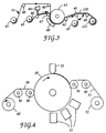
- the abrasive article 20 of the invention comprises a backing 21 having a plurality of abrasive composites 22 bonded to the backing.
- the abrasive composites comprises a plurality of abrasive particles 23 that are dispersed in a binder 24.
- abrasive particles 23 that are dispersed in a binder 24.
- the boundaries forming the sides of the shape also are planar.
- the number of planes for a given shape can vary depending upon the desired geometry, for instance the number of planes can range from four to over 20. Generally, there are between four to ten planes, preferably between four to six planes. These planes intersect to form the desired shape and the angles at which these planes intersect will determine the shape dimensions.
- the abrasive composite 12 has a boundary 15 which is planar.
- the side planes 15a and 15b intersect at an angle ⁇ , with cross-section 15c facing the viewer and is coplanar with the page.
- a key aspect of this invention is that at least one the abrasive composites has a different dimersion from another abrasive composite in the array.
- the different dimension is established between at least one pair of adjacent composites, and even more preferably, established for each and every pair of adjacent composites provided on the surface of the abrasive article.
- the terminology of "every pair" of adjacent composites encompasses an arbitrary consideration of every composite on the surface of the abrasive article as paired with its adjacent composite. In general, at least 10% of the pairs of adjacent composites have a different dimension therebetween, preferably at least 30%, more preferably at least 50%.
- substantially 100% of the abrasive composites have a different dimension from its respective paired adjacent abrasive composite.
- the result of this proviso of different dimensions between abrasive composites, viz. between adjacent pairs of abrasive composites, results in an abrasive article that produces a relatively finer surface finish on the workpiece being abraded or refined. Since the dimensions of adjacent abrasive composites vary, there is a reduced tendency for scribed grooves to be imparted by the precisely abrasive composites into the workpiece surface.
- the effect of the invention of decreasing scribing while achieving high-cut rates and fine finishes may not be satisfactorily realized.
- the number of pairs of adjacent abrasive composites that have different dimensions is selected to minimize or reduce scribing. The percentage of the total abrasive composites that this number of pairs represents will depend upon several factors such as the workpiece type, abrading interface pressure, abrasive article rotation speed and other typical abrading conditions.
- the abrasive composites having identical shapes if present, preferably should not be located directly adjacent to or next to one another in order to fully realize the benefits of the invention.
- two abrasive composites in the abrasive article may have shapes defined by same dimensions, but, preferably, the two abrasive composites should be separated from one another in the array of composites by at least one intervening abrasive composite that differs in a dimension from each.
- At least one dimension associated with at least one of the abrasive composites that is different from another abrasive composite there must be at least one dimension associated with at least one of the abrasive composites that is different from another abrasive composite.
- These dimensions can be varied in a variety of ways, such as by providing a different length of an edge at the intersection of two planar surfaces of a shape of a composite; by providing a different angle formed at the meeting edge of two adjacent planar surfaces of a shape of a composite; or by providing different types of geometrical shapes for the abrasive composites to provide either a different edge length and/or a different angle.
- the length or dimensions of the edges in composites, particularly adjacent composites, each having a pyramidal shape as the geometrical shape and a common height of between 25 and 1020 micrometers generally can differ from at least about 1 to about 500 micrometers, and more preferably between 5 to 250 micrometers.
- the length of the at least one edge of a first composite in the array has a length which varies with respect to the length of any edge of a second composite in a ratio between 10:1 to 1:10, not inclusive of 1:1, and preferably as between two adjacent composites.
- a preferred geometrical shape is a pyramid and the pyramid can be a four or five side sided (inclusive of the base) pyramid.
- all composite shapes are pyramidal.
- the dimensional variance is achieved between adjacent pyramidal-shaped composites by varying the angle formed by a side surface with the backing in adjacent pyramids. For example, angles ⁇ and ⁇ formed by the sides of adjacent pyramidal shaped composites, such as depicted in Figure 1, are different angles from each other and each have a value of between 0° and 90° (i.e. non-inclusive of 0° and 90°).
- the angle ⁇ or ⁇ formed between a side surface of the pyramidal-shaped composites and an imaginary plane 17 ( Figure 1) extending normal to the intersection of the respective side surface and the backing should be greater than or equal to 8°, but less than or equal to 45° From a practical standpoint, angles less than 8° may release cured composite shapes from the production tool with greater difficulty. On the other hand, angles greater than 45° may unduly enlarge the spacing between adjacent abrasive composites such that insufficient abrading surfaces are provided over the area of the backing.
- angles for ⁇ und ⁇ wherein each have a value between 0° and 90° and which differ in magnitude by at least about 1°, and more preferably at least about 5°.
- this proviso with respect to material-included angle ⁇ should be used together with the above-mentioned proviso that intervening angles ⁇ and ⁇ between adjacent composites be provided as different and randomly selected between 0° and 90° as explained hereinabove.
- angles made by the various surface planes with the backing do not necessarily have to be the same for a given composite.
- the angles formed by any of the first, second and third side planes with the backing can be different from each other.
- the angle at which the side surfaces intersect with each other will also vary as the angle formed between the side surface and the backing are varied.
- ⁇ as the right half angle ( Figure 1)
- ⁇ as the left half angle facing ⁇
- ⁇ is randomly chosen for the adjacent abrasive composite in the adjacent row of composites
- a new ⁇ as left half angle
- ⁇ is randomly selected between 0° and 90° degrees
- a new value for ⁇ , as the facing right half angle, of the adjacent composite car be randomly selected in the range of 0° to 90° degrees, and so forth throughout the array.
- This practice is desirable in order to provide a more uniform distribution of angles between 0° and 90° degrees throughout the array of abrasive composites in the article.
- the angle values once so selected for the abrasive composites in the array, can be used to determine and predicate the pattern and shapes of indentations formed by a diamond turning machine in the surface of a metal production tool or production tool, which, in turn, can be used to make the abrasive composite articles of the invention by methods described herein.
- the height and geometrical shape of all the composites is the same. This height is the distance of the abrasive composite from the backing to its outermost point before the abrasive article is used. If the height and shape are constant, it is then preferred to have the angle between planes vary.
- the peaks of the abrasive composites do not align in a column which is parallel to the abrading direction performed in the machine direction. If the abrasive composite peaks align in a column parallel to the abrading direction, this tends to result in grooves imparted to the workpiece and a coarser surface finish. Thus, it is preferred that the abrasive composites be offset from one another to prevent this alignment.
- abrasive composites there are at least 5 individual abrasive composites per square centimeter. In some instances, there may be at least about 100 individual abrasive composites/square centimeter or higher, and more preferably, about 2,000 to 10,000 abrasive composites/square centimeter. There is no operational upper limit on the density of the abrasive composites; although, from a practical standpoint, at some point it may not be possible to increase the cavity density and/or form precisely shaped cavities in the surface of the production tooling preferably used to make the array of abrasive composites.
- this number of abrasive composites result in an abrasive article that has a relatively high rate of cut, a long life, but also results in a relatively fine surface finish on the workpiece being abraded. Additionally, with this number of abrasive composites there is a relatively low unit force per each abrasive composite. In some instances, this can result in better, more consistent, breakdown of the abrasive composite.
- the first step in making the abrasive article is to prepare an abrasive slurry.
- the abrasive slurry is made by combining together by any suitable mixing technique the binder precursor, the abrasive particles, and the optional additives. Examples of mixing techniques include low shear and high shear mixing, with high shear mixing being preferred. Ultrasonic energy may also be utilized in combination with the mixing step to lower the abrasive slurry viscosity.
- the abrasive particles are gradually added into the binder precursor. The amount of air bubbles in the abrasive slurry can be minimized by pulling a vacuum during the mixing step, for example, by employing conventional vacuum-assisted methods and equipment.
- the abrasive slurry In some instances it is preferred to heat, generally in the range of 30 to 70°C, the abrasive slurry to lower the viscosity. It is important the abrasive slurry have a rheology that coats well and in which the abrasive particles and other fillers do not settle.
- thermosetting binder precursor the energy source can be thermal energy or radiation energy depending upon the binder precursor chemistry. If a thermoplastic binder precursor is employed the thermoplastic is cooled such that it becomes solidified and the abrasive composite is formed. Other more detailed aspects of the method(s) to make the abrasive article of the invention will be described hereinbelow.
- a production tool is important, from both practical and technological standpoints, in making an abrasive article of the invention, especially in view of the relatively small sizes of the abrasive composites.
- the production tool contains a plurality of cavities. These cavities are essentially the inverse shape of the abrasive composite desired and are responsible for generating the shape of the abrasive composites.
- the dimensions of the cavities are selected to provide the desired shape and dimensions of the abrasive composites. If the shape or dimensions of the cavities are not properly fabricated, the resulting production tool will not provide the desired dimensions for the abrasive composites.
- the cavities can be present in a dot like pattern with spaces between adjacent cavities or the cavities can abutt against one another.
- the cavities butt up against one another to facilitate release of the shaped and cured abrasive slurry.
- the shape, of the cavities is selected such that the cross-sectional area of the abrasive composite decreases in the direction away from the backing.
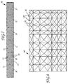
- Figure 7 is a top view representation of a production tool 70 that can be used to make an abrasive article of the invention.
- the side edges 71 of the production tool are parallel to the machine direction (not shown) of the production tool and are perpendicular to the transverse width direction of the production tool.
- Cavitites 74 are delimited by intersecting upraised portions represented by solid lines 72 and 73.
- the production tool has six distinct groups A, B, C, D, E and F of cavities, wherein in each group the cavities are aligned in parallel rows bounded by upraised portions 72, wherein the upraised portions 72 and 73 are the nondeformed (noncavitated) remainder of the tooling sheet.
- These groups A-E are arranged head-to-tail along the length of the tooling, as shown in Figure 7.
- the rows of cavities in each group that are aligned most closely with side edges 71 trace imaginary lines extending at non-parallel (nonzero) angles to the machine direction of the production tool, and which angles differ from group A to group B to group C, and so forth up to group F.
- the angles of the rows of cavities (and intervening upraised portions 72) made with the side edges 71 should be established as between 0° to 90°. Scribing problems can arise at either 0° or 90° angles for rows of cavities with the side edges 71.
- angles of 5° to 85° are selected for the angles of the rows of cavities with the machine direction more assuredly avoid scribing problems.
- angles of the rows of cavities preferably alternate between clockwise and counterclockwise directionality from group to group, as shown in Figure 7.
- the angle formed between rows of cavities and upraised portions 72 and the side edges 71 can be selected to be the same or different in absolute magnitude from set to set.
- An abrasive article formed with production tool 70 by methods described herein will have an array of abrasive composites formed in the inverse shape to the surface profile presented by the array of cavities in the production tool, such production tool 70.
- the cavities in the production tool can be arranged to be laterally offset, i.e., nonaligned, from one another in the direction advancing parallel to the side edges of the production tool (nondepicted). That is, this embodiment provides an optional manner of forming an array of abrasive composites and intervening grooves which are not arranged in rows which extend parallel to the the side edges of the abrasive article. Instead, the abrasive composites are staggered from each other and non-aligned when viewed from the front of the abrasive article into the direction parallel to the side edges of the abrasive article.
- the production tool can be a belt, a sheet, a continuous sheet or web, a coating roll such as a rotogravure roll, a sleeve mounted on a coating roll, or die.
- the production tool can be composed of metal, (e.g., nickel), metal alloys (e.g., nickel alloys), plastic (e.g., polypropylene, an acrylic plastic), or any other conveniently formable material.
- the metal production tool can be fabricated by any conventional technique such as engraving, hobbing, electroforming, diamond turning, and the like.
- thermoplastic production tool can be made by replication off a metal master tool.
- the metal master will have the inverse pattern desired for the production tool.
- the metal master can be made with the same basic techniques useful in directly making the production tool, e.g., by diamond turning a metal surface.
- a thermoplastic sheet material can be heated and optionally along with the metal master such that the thermoplastic material is embossed with the surface pattern presented by the metal master by pressing the two surfaces together.
- the thermoplastic can also be extruded or cast onto to the metal master and then pressed.
- the thermoplastic material is cooled to solidify and produce the production tool.
- preferred thermoplastic production tool materials include polyester, polycarbonates, polyvinyl chloride, polypropylene, polyethylene and combinations thereof.
- a plastic production tool can be directly made, without the need of a master by engraving or diamond turning a predetermined array of cavities, which have the inverse shape of the abrasive composites desired, into a surface of the plastic sheet. If a thermoplastic production tool is utilized, then care must be taken not to generate excessive heat, particularly during the solidifying step, that may distort the thermoplastic production tool. Other suitable methods of production tooling and metal masters are discussed in commonly assigned U.S. Patent Application No. 08/004,929 (Spurgeon et al.), filed 14 December 1993.
- a preferred method of making a polymeric production tool of the invention of the type depicted in Figure 7 involves the use of a nickel-plated metal master configured in a drum form.
- Several flat sections of nickel-plated master, each about 30 centimeters in length, with the varied shapes of indentations corresponding to the shapes desired for the abrasive composites are provided in a surface thereof, are produced by diamond turning with the aid of a computer directing the cutting action performed by the diamond turning machine.
- These sections of metal master are welded together head-to-tail, with the grooves of section being at a non-zero angle to the grooves of the next adjacent section. This chain of sections is then fixed to a drum so that the composites are continuous around the circumference of the drum.
- the production tool is cast by extruding polymeric resin onto the drum and passing the extrudant between a nip roll and the drum, and then cooling the extrudant to form a production tool in sheet form having an array of cavities formed on the surface thereof in inverse correspondence to the surface indentations presented by the master on the drum. This process can be conducted continuously to produce a polymeric tool of any desired length.
- the binder precursor is cured or polymerized. This polymerization is generally initiated upon exposure to an energy source.
- energy sources include thermal energy and radiation energy. The amount of energy depends upon several factors such as the binder precursor chemistry, the dimensions of the abrasive slurry, the amount and type of abrasive particles and the amount and type of the optional additives.
- thermal energy the temperature can range from about 30 to 150°C, generally between 40 to 120°C.
- the time can range from about 5 minutes to over 24 hours.
- the radiation energy sources include electron beam, ultraviolet light, or visible light.
- Electron beam radiation which is also known as ionizing radiation, can be used at an energy level of about 0.1 to about 10 Mrad, preferably at an energy level of about 1 to about 10 Mrad.
- Ultraviolet radiation refers to non-particulate radiation having a wavelength within the range of about 200 to about 400 nanometers, preferably within the range, of about 250 to 400 nanometers. It is preferred that 300 to 600 Watt/inch (120-240 Watt/cm) ultraviolet lights are used.
- Visible radiation refers to non-particulate radiation having a wavelength within the range of about 400 to about 800 nanometers, preferably in the range of about 400 to about 550 nanometers. It is preferred that 300 to 600 Watt/inch (120-240 Watt/cm) visible lights are used.
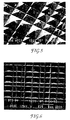
- FIG. 3 One method to make the abrasive article of the invention is illustrated in Figure 3.
- Backing 41 leaves an unwind station 42 and at the same time the production tool 46 leaves an unwind station 45.
- Cavities (not depicted) formed in the upper surface of production tool 46 are coated and filled with an abrasive slurry by means of coating station 44.
- coating station 44 can be relocated to deposit the slurry on backing 41 instead of the production tool before reaching drum 43 and the same ensuing steps are followed as used for coating the production tooling as described below. Either way, it is possible to heat the abrasive slurry (not shown) and/or subject the slurry to ultrasonics prior to coating to lower the viscosity.
- the coating station can be any conventional coating means such as drop die coater, knife coater, curtain coater, vacuum die coater or a die coater. During coating the formation of air bubbles should be minimized.
- the preferred coating technique uses a vacuum die coater, which can be of the type such as described in U.S. Patent Nos. 3,594,865; 4,959,265 and 5,077,870. After the production tool is coated, the backing and the abrasive slurry are brought into contact by any means such that the abrasive slurry wets the front surface of the backing.
- the abrasive slurry is brought into contact with the backing by means of contact nip roll 47, and contact nip roll 47 forces the resulting construction against support drum 43.
- any convenient form of energy 48 is transmitted into the abrasive slurry that is adequate to at least partially cure the binder precursor.
- the term partial cure is meant that the binder precursor is polymerized to such a state that the abrasive slurry does not flow from an inverted test tube.
- the binder precursor can be fully cured once it is removed from the production tool by any energy source.
- the production tool is rewound on mandrel 49 so that the production tool can be reused again.
- abrasive article 120 is wound on mandrel 121.
- the binder precursor can then be fully cured by either time and/or exposure to an energy source. Additional steps to make the abrasive article according to this first method is further described in U.S. Patent No. 5,152,917 (Pieper et al.) or the above-mentioned U.S. Patent Application No. 08/004,929 (Spurgeon et al.). Other guide rolls are used where convenient and are designated rolls 40.
- the binder precursor is cured by radiation energy.
- the radiation energy can be transmitted through the production tool or backing so long as the production tool or backing does not appreciably absorb the radiation energy. Additionally, the radiation energy source should not appreciably degrade the production tool. It is preferred to use a thermoplastic production tool and ultraviolet or visible light.
- the abrasive slurry can be coated onto the backing and not into the cavities of the production tool.
- the abrasive slurry coated backing is then brought into contact with the production tool such that the abrasive slurry flows into the cavities of the production tool.
- the remaining steps to make the abrasive article are the same as detailed above.
- a second method for making the abrasive article is illustrated in Figure 4.
- the production tool 55 is provided in the outer surface of a drum, e.g., as a sleeve which is secured around the circumference of a drum in separate sheet form (e.g., as a heat-shrunk nickel form) in any convenient manner.
- Backing 51 leaves an unwind station 52 and the abrasive slurry is coated into the cavities of the production tool 55 by means of the coating station 53.
- the abrasive slurry can be coated onto the backing by any technique such as drop die coater, roll coater, knife coater, curtain coater, vacuum die coater, or a die coater.
- the backing and the production tool containing the abrasive slurry are brought into contact by a nip roll 56 such that the abrasive slurry wets the front surface of the backing.
- the binder precursor in the abrasive slurry is at least partially cured by exposure to an energy source 57. After this at least partial cure, the abrasive slurry is converted to an abrasive composite that is bonded or adhered to the backing.
- the energy source can be thermal energy or radiation energy. If the energy source is either ultraviolet light or visible light, the backing should be transparent to ultraviolet or visible light. An example of such a backing is polyester backing. Other guide and contact rolls can be used where convenient and are designated rolls 50.
- the abrasive slurry can be coated directly onto the front surface of the backing by moving coating station 53 to a location upstream from roll 56.
- the abrasive slurry coated backing is then brought into contact with the production tool such that the abrasive slurry wets into the cavities of the production tool.
- the remaining steps to make the abrasive article are the same as detailed above.
- the abrasive article After the abrasive article is made, it can be flexed and/or humidified prior to converting.
- the abrasive article can be converted into any desired form such as a cone, endless belt, sheet, disc, etc. before the abrasive article is put into service.
- Another embodiment of this invention pertains to a method of refining a workpiece surface.
- This method involves bringing into frictional contact the abrasive article of this invention with a workpiece.
- the term refine means that a portion of the workpiece is abraded away by the abrasive article.
- the surface finish associated with the workpiece surface is reduced after this refining process.
- One typical surface finish measurement is Ra; Ra is the arithmetic surface finish generally measured in microinches or micrometers.
- the surface finish can be measured by a profilometer, such as that available under the trade designation Perthometer or Surtronic.
- the workpiece can be any type of material such as metal, metal alloy, exotic metal alloy, ceramic, glass, wood, wood like material, composites, painted surface, plastic, reinforced plastic, stone, and combinations thereof.
- the workpiece may be flat or may have a shape or contour associated with it. Examples of workpieces include glass ophthalmic lenses, plastic ophthalmic lenses, glass television screens, metal automotive components, plastic components, particle board, cam shafts, crank shafts, furniture, turbine blades, painted automotive components, magnetic media, and the like.
- the force at the abrading interface can range from about 0.1 kg to over 1000 kg. Generally this range is between 1 kg to 500 kg of force at the abrading interface.
- a liquid present during abrading can be water and/or an organic compound. Examples of typical organic compounds include lubricants, oils, emulsified organic compounds, cutting fluids, soaps, or the like. These liquids may also contain other additives such as defoamers, degreasers, corrosion inhibitors, or the like.
- the abrasive article may oscillate at the abrading interface during use. In some instances, this oscillation may result in a finer surface on the workpiece being abraded.
- Figure 8 includes a representative topographical top view (and side views) of an abrasive article 85 of the invention wherein an abrasive composite therein is designated 80 having a face 82 and apex 81.
- the pyramidal shapes as a whole, align in rows, and therefore, the apices of the abrasive composites are aligned irrespective of the differences in side dimensions between adjacent abrasive composites facing each other across common grooves.
- This arrangement results in scratches imparted into the workpiece by the abrasive composites which are continuously crossed over. This continuous crossing of previous scratches results in the aggregate, in the finer surface finish.
- the abrasive article of the invention can be used by hand or used in combination with a machine. At least one or both of the abrasive article and the workpiece is moved relative to the other.
- the abrasive article can be converted into a belt, tape rolls, disc, sheet, and the like. For belt applications, the two free ends of an abrasive sheet are joined together and a splice is formed. It is also within the scope of this invention to use a spliceless belt.
- the endless abrasive belt traverses over at least one idler roll and a platen or contact wheel. The hardness of the platen or contact wheel is adjusted to obtain the desired rate of cut and workpiece surface finish.
- the abrasive belt speed ranges anywhere from about 150 to 5000 meters per minute, generally between 500 to 3000 meters per minute. Again this belt speed depends upon the desired cut rate and surface finish.
- the belt dimensions can range from about 5 mm to 1 meter wide and from about 5 cm to 10 meters long.
- Abrasive tapes are continuous lengths of the abrasive article. They can range in width from about 1 mm to 1 meter, generally between 5 mm to 25 cm.
- the abrasive tapes are usually unwound, traverse over a support pad that forces the tape against the workpiece and then rewound.
- the abrasive tapes can be continuously feed through the abrading interface and can be indexed.
- the abrasive disc which also includes what is known in the abrasive art as “daisies”, can range from about 50 mm to 1 meter in diameter.
- abrasive discs are secured to a back-up pad by an attachment means. These abrasive discs can rotate between 100 to 20,000 revolutions per minute, typically between 1,000 to 15,000 revolutions per minute.
- An abrasive slurry was prepared that contained 20.3 parts TMPTA, 8.7 parts TATHEIC, 0.3 parts PH2, 1 part ASF, 1 part SCA and 69 parts of grade P-320 FAO.
- the slurry was mixed for 20 minutes at 1200 rpm using a high shear mixer.
- the production tool was a continuous web made from a polypropylene sheet material commercially available from Exxon under the trade designation "PolyPro 3445".
- the production tool was embossed off of a nickel-plated master.
- the master tool was made by diamond cutting a pattern of varying dimension grooves and indentations according to the computer programs described in the APPENDIX, and then nickel plated.
- the APPENDIX includes the source code for four computer programs, which, in general, comprises a first program entitled “VARI-1.BAS”, which generated and determined random left and right angles for side surfaces of five sided pyramidal shapes and also the material included angles for these shapes; the second program entitled “VARI-STAT.BAS” statistically tallied the number and values of the left, right, and material included angles in x and y coordinates in the array of shapes to assure randomness; the third program entitled “TOPVIEW.BAS” took the random angle file and calculated where the valleys and peaks appear for the shapes having the, angles determined by the first program for a square inch (6.5 cm 2 ) and printed out a display on a computer screen or printer of the topography of the array of shapes; and the fourth program "MAKETAPE.BAS” took the determined angles and generated a code to control the number and type of grooves required to be cut by the diamond turning machine to make a 22.5 inch (57 cm) wide pattern of random shapes generated by the first program.
- the production tool as made from the master tool made using the above-mentioned four programs, contained an array of cavities that were inverted five sided pyramids (inclusive of the mouth of the cavity as a "base") that had a constant depth of about 355 micrometers but varied in dimension between 8 and 45 degrees for adjacent cavities in terms of the angle made by side faces with the intersection of a plane extending normal to the plane of tool and the material included angle or apex angle of each composite was at least 25 degrees.
- the coated abrasive article was converted into 7.6 cm by 335 cm endless belt and tested on a constant load surface grinder.
- a pre-weighed, 4150 mild steel workpiece approximately 2.5 cm by 5 cm by 18 cm was mounted in a holder.
- the workpiece was positioned vertically, with the 2.5 cm by 18 cm face facing an approximately 36 cm diameter 65 Shore A durometer serrated rubber contact wheel with one on one lands over which was entrained the coated abrasive belt.
- the workpiece was then reciprocated vertically through an 18 cm path at the rate of 20 cycles per minute, while a spring loaded plunger urged the workpiece against the belt with a load of 4.5 kg (10 lbs) as the belt was driven at about 2050 meters per minute.
- the workpiece holder assembly was removed and re-weighed, the amount of stock removed calculated by subtracting the abraded weight from the original weight, and a new, pre-weighed workpiece and holder were mounted on the equipment. Additionally, the surface finish (Ra) and, in some cases, the Rtm, of the workpiece was also measured and these procedures will be described below.
- the test endpoint was when the amount of steel removed in the thirty second interval was less than one third the value of the steel removed in the first thirty seconds of grinding or until the workpiece burned, i.e., became discolored.
- a maple dowel rod that had a diameter of approximately 3 cm was installed on a lathe.
- the dowel rod was rotated at about 3800 rpm.
- a strip of abrasive article (1 inch (2.54 cm) wide and 12 inches (30.5 cm) long) was held against the dowel rod without any oscillation for approximately 15 to 20 seconds.
- the dowel rod was stained with a cherry oil stain commercially available from Watco.
- Ra is a common measure of roughness used in the abrasives industry. Ra is defined as the arithmetic mean of the departures of the roughness profile from the mean line. Ra was measured with a profilometer probe, which was a diamond tipped stylus. In general, the lower the Ra value was, the smoother or finer the workpiece surface finish. The results were recorded in micrometers. The profilometer used was a Perthen M4P.
- Rtm is a common measure of roughness used in the abrasive industry.
- Rtm is defined as the mean of five individual roughness depths of five successive measuring lengths, where an individual roughness depth is the vertical distance between the highest and lowest points in a measuring length.
- Rtm is measured the same as Ra. The results are recorded in micrometers. In general, the lower the Rtm, the smoother the finish.
- Example 1 was made according to the "General Procedure for Making the Abrasive Article" describe herein.
- Comparative Example A was a grade P320 3M 201E Three-M-ite Resin Bond cloth JE-VF coated abrasive commercially available from 3M Company, St. Paul, MN. These abrasive products were tested according to Test Procedure I and the test results can be found in Table 1. Also, additional Example 1A and Comparative Example AA were performed wherein Example 1 and Comparative Example A were repeated, except that Test Procedure II was used in lieu of Test Procedure I. The results also are summarized in Table 1. Run Ex. 1 C.Ex.
- This set of examples compared the abrasive article of the invention with abrasive articles that had only one commonly shaped and dimensioned type of abrasive composite present on the backing. All of these examples were made according to "General Procedure for Making the Abrasive Article," described above, except for the following changes.
- the abrasive slurry consisted of 20.3 parts TMPTA, 8.7 parts TATHEIC, 1 part PH2, 1 part ASF, 1 part SCA, and 69 parts of 40 micrometer WAO.
- the production tool for Comparative Examples B through E was an embossed polypropylene thermoplastic continuous web that contained five sided pyramidal type cavities (inclusive of the mouth of the cavity as a "base").
- the cavities for Comparative Examples B through E were all identical in dimensions and the cavities butted up against one another.
- the height of the cavities for Comparative Example B was about 178 micrometers
- for Comparative Example C was about 63.5 micrometers
- for Comparative Example D was about 711 micrometers
- Comparative Example E was about 356 micrometers.
- Example 2 and Comparative Examples B through E then were tested according to Test Procedure III above.
- the stained maple dowel rod abraded with Comparative Examples B through E showed evidence of grooves visible by the naked eye.
- the stained maple dowel rod abraded with Example 2 representing the present invention showed no evidence of grooves visible by the naked eye and produced a very fine finish on the wood workpiece.
Applications Claiming Priority (3)
| Application Number | Priority Date | Filing Date | Title |
|---|---|---|---|
| US12030093A | 1993-09-13 | 1993-09-13 | |
| US120300 | 1993-09-13 | ||
| PCT/US1994/000754 WO1995007797A1 (en) | 1993-09-13 | 1994-01-21 | Abrasive article, method of manufacture of same, method of using same for finishing, and a production tool |
Publications (2)
| Publication Number | Publication Date |
|---|---|
| EP0720520A1 EP0720520A1 (en) | 1996-07-10 |
| EP0720520B1 true EP0720520B1 (en) | 1999-07-28 |
Family
ID=22389438
Family Applications (1)
| Application Number | Title | Priority Date | Filing Date |
|---|---|---|---|
| EP94908617A Expired - Lifetime EP0720520B1 (en) | 1993-09-13 | 1994-01-21 | Abrasive article, method of manufacture of same, method of using same for finishing, and a production tool |
Country Status (16)
| Country | Link |
|---|---|
| US (5) | US5672097A (no) |
| EP (1) | EP0720520B1 (no) |
| JP (2) | JP3587209B2 (no) |
| KR (1) | KR100313263B1 (no) |
| CN (1) | CN1067315C (no) |
| AT (1) | ATE182502T1 (no) |
| AU (1) | AU679968B2 (no) |
| BR (1) | BR9407536A (no) |
| CA (1) | CA2170989A1 (no) |
| DE (1) | DE69419764T2 (no) |
| ES (1) | ES2134930T3 (no) |
| NO (1) | NO961011L (no) |
| RU (1) | RU2124978C1 (no) |
| SG (1) | SG64333A1 (no) |
| WO (1) | WO1995007797A1 (no) |
| ZA (1) | ZA94585B (no) |
Families Citing this family (353)
| Publication number | Priority date | Publication date | Assignee | Title |
|---|---|---|---|---|
| US6258137B1 (en) * | 1992-02-05 | 2001-07-10 | Saint-Gobain Industrial Ceramics, Inc. | CMP products |
| DE69419764T2 (de) * | 1993-09-13 | 1999-12-23 | Minnesota Mining & Mfg | Schleifartikel, verfahren zur herstellung desselben, verfahren zur verwendung desselben zum endbearbeiten, und herstellungswerkzeug |
| CA2134156A1 (en) * | 1993-11-22 | 1995-05-23 | Thomas P. Klun | Coatable compositions, abrasive articles made therefrom, and methods of making and using same |
| WO1996027189A1 (en) * | 1995-03-02 | 1996-09-06 | Minnesota Mining And Manufacturing Company | Method of texturing a substrate using a structured abrasive article |
| WO1997006926A1 (en) | 1995-08-11 | 1997-02-27 | Minnesota Mining And Manufacturing Company | Method of making a coated abrasive article having multiple abrasive natures |
| US5975987A (en) * | 1995-10-05 | 1999-11-02 | 3M Innovative Properties Company | Method and apparatus for knurling a workpiece, method of molding an article with such workpiece, and such molded article |
| US5700302A (en) * | 1996-03-15 | 1997-12-23 | Minnesota Mining And Manufacturing Company | Radiation curable abrasive article with tie coat and method |
| AU6593796A (en) * | 1996-07-23 | 1998-02-10 | Minnesota Mining And Manufacturing Company | Structured abrasive article containing hollow spherical filler |
| US6080215A (en) * | 1996-08-12 | 2000-06-27 | 3M Innovative Properties Company | Abrasive article and method of making such article |
| US5893935A (en) * | 1997-01-09 | 1999-04-13 | Minnesota Mining And Manufacturing Company | Method for making abrasive grain using impregnation, and abrasive articles |
| US5876268A (en) * | 1997-01-03 | 1999-03-02 | Minnesota Mining And Manufacturing Company | Method and article for the production of optical quality surfaces on glass |
| US6120352A (en) * | 1997-03-06 | 2000-09-19 | Keltech Engineering | Lapping apparatus and lapping method using abrasive sheets |
| US6149506A (en) * | 1998-10-07 | 2000-11-21 | Keltech Engineering | Lapping apparatus and method for high speed lapping with a rotatable abrasive platen |
| US6231629B1 (en) | 1997-03-07 | 2001-05-15 | 3M Innovative Properties Company | Abrasive article for providing a clear surface finish on glass |
| US5888119A (en) * | 1997-03-07 | 1999-03-30 | Minnesota Mining And Manufacturing Company | Method for providing a clear surface finish on glass |
| US5910471A (en) * | 1997-03-07 | 1999-06-08 | Minnesota Mining And Manufacturing Company | Abrasive article for providing a clear surface finish on glass |
| US6224465B1 (en) * | 1997-06-26 | 2001-05-01 | Stuart L. Meyer | Methods and apparatus for chemical mechanical planarization using a microreplicated surface |
| US5876470A (en) * | 1997-08-01 | 1999-03-02 | Minnesota Mining And Manufacturing Company | Abrasive articles comprising a blend of abrasive particles |
| US6258311B1 (en) * | 1997-08-25 | 2001-07-10 | Velcro Industries B.V. | Forming mold cavities |
| DE69822852T2 (de) | 1997-08-25 | 2005-03-24 | Velcro Industries B.V. | Herstellen von formvertiefungen |
| US5946991A (en) | 1997-09-03 | 1999-09-07 | 3M Innovative Properties Company | Method for knurling a workpiece |
| US6121143A (en) * | 1997-09-19 | 2000-09-19 | 3M Innovative Properties Company | Abrasive articles comprising a fluorochemical agent for wafer surface modification |
| US5928394A (en) * | 1997-10-30 | 1999-07-27 | Minnesota Mining And Manufacturing Company | Durable abrasive articles with thick abrasive coatings |
| US6102777A (en) * | 1998-03-06 | 2000-08-15 | Keltech Engineering | Lapping apparatus and method for high speed lapping with a rotatable abrasive platen |
| US6136008A (en) * | 1998-03-19 | 2000-10-24 | 3M Innovative Properties Company | Skin abrader for biomedical electrode |
| JPH11300829A (ja) * | 1998-04-22 | 1999-11-02 | Toyota Motor Corp | エンボス模様付き金属薄膜の製造方法 |
| US6053956A (en) * | 1998-05-19 | 2000-04-25 | 3M Innovative Properties Company | Method for making abrasive grain using impregnation and abrasive articles |
| US6634935B2 (en) * | 1998-12-01 | 2003-10-21 | Nutool, Inc. | Single drive system for a bi-directional linear chemical mechanical polishing apparatus |
| US6589105B2 (en) * | 1998-12-01 | 2003-07-08 | Nutool, Inc. | Pad tensioning method and system in a bi-directional linear polisher |
| US6464571B2 (en) * | 1998-12-01 | 2002-10-15 | Nutool, Inc. | Polishing apparatus and method with belt drive system adapted to extend the lifetime of a refreshing polishing belt provided therein |
| US6468139B1 (en) * | 1998-12-01 | 2002-10-22 | Nutool, Inc. | Polishing apparatus and method with a refreshing polishing belt and loadable housing |
| US6312484B1 (en) | 1998-12-22 | 2001-11-06 | 3M Innovative Properties Company | Nonwoven abrasive articles and method of preparing same |
| US6239049B1 (en) | 1998-12-22 | 2001-05-29 | 3M Innovative Properties Company | Aminoplast resin/thermoplastic polyamide presize coatings for abrasive article backings |
| US6238449B1 (en) | 1998-12-22 | 2001-05-29 | 3M Innovative Properties Company | Abrasive article having an abrasive coating containing a siloxane polymer |
| US6503564B1 (en) * | 1999-02-26 | 2003-01-07 | 3M Innovative Properties Company | Method of coating microstructured substrates with polymeric layer(s), allowing preservation of surface feature profile |
| US6634929B1 (en) | 1999-04-23 | 2003-10-21 | 3M Innovative Properties Company | Method for grinding glass |
| US6458018B1 (en) | 1999-04-23 | 2002-10-01 | 3M Innovative Properties Company | Abrasive article suitable for abrading glass and glass ceramic workpieces |
| JP4629174B2 (ja) * | 1999-10-15 | 2011-02-09 | 大日本印刷株式会社 | 絹の布地調シート作成方法および装置 |
| US8111401B2 (en) | 1999-11-05 | 2012-02-07 | Robert Magnusson | Guided-mode resonance sensors employing angular, spectral, modal, and polarization diversity for high-precision sensing in compact formats |
| US7167615B1 (en) | 1999-11-05 | 2007-01-23 | Board Of Regents, The University Of Texas System | Resonant waveguide-grating filters and sensors and methods for making and using same |
| US6776699B2 (en) | 2000-08-14 | 2004-08-17 | 3M Innovative Properties Company | Abrasive pad for CMP |
| US7142296B2 (en) * | 2000-10-30 | 2006-11-28 | Sru Biosystems, Inc. | Method and apparatus for detecting biomolecular interactions |
| US20030113766A1 (en) * | 2000-10-30 | 2003-06-19 | Sru Biosystems, Llc | Amine activated colorimetric resonant biosensor |
| US7202076B2 (en) | 2000-10-30 | 2007-04-10 | Sru Biosystems, Inc. | Label-free high-throughput optical technique for detecting biomolecular interactions |
| US7875434B2 (en) * | 2000-10-30 | 2011-01-25 | Sru Biosystems, Inc. | Label-free methods for performing assays using a colorimetric resonant reflectance optical biosensor |
| US7371562B2 (en) | 2000-10-30 | 2008-05-13 | Sru Biosystems, Inc. | Guided mode resonant filter biosensor using a linear grating surface structure |
| US20030092075A1 (en) * | 2000-10-30 | 2003-05-15 | Sru Biosystems, Llc | Aldehyde chemical surface activation processes and test methods for colorimetric resonant sensors |
| US7118710B2 (en) * | 2000-10-30 | 2006-10-10 | Sru Biosystems, Inc. | Label-free high-throughput optical technique for detecting biomolecular interactions |
| US7070987B2 (en) * | 2000-10-30 | 2006-07-04 | Sru Biosystems, Inc. | Guided mode resonant filter biosensor using a linear grating surface structure |
| US7023544B2 (en) | 2000-10-30 | 2006-04-04 | Sru Biosystems, Inc. | Method and instrument for detecting biomolecular interactions |
| US7306827B2 (en) * | 2000-10-30 | 2007-12-11 | Sru Biosystems, Inc. | Method and machine for replicating holographic gratings on a substrate |
| US7101660B2 (en) | 2000-10-30 | 2006-09-05 | Sru Biosystems, Inc. | Method for producing a colorimetric resonant reflection biosensor on rigid surfaces |
| US7175980B2 (en) * | 2000-10-30 | 2007-02-13 | Sru Biosystems, Inc. | Method of making a plastic colorimetric resonant biosensor device with liquid handling capabilities |
| US6951715B2 (en) * | 2000-10-30 | 2005-10-04 | Sru Biosystems, Inc. | Optical detection of label-free biomolecular interactions using microreplicated plastic sensor elements |
| US7153702B2 (en) * | 2000-10-30 | 2006-12-26 | Sru Biosystems, Inc. | Label-free methods for performing assays using a colorimetric resonant reflectance optical biosensor |
| US7217574B2 (en) * | 2000-10-30 | 2007-05-15 | Sru Biosystems, Inc. | Method and apparatus for biosensor spectral shift detection |
| US7300803B2 (en) * | 2000-10-30 | 2007-11-27 | Sru Biosystems, Inc. | Label-free methods for performing assays using a colorimetric resonant reflectance optical biosensor |
| US7615339B2 (en) * | 2000-10-30 | 2009-11-10 | Sru Biosystems, Inc. | Method for producing a colorimetric resonant reflection biosensor on rigid surfaces |
| US7264973B2 (en) * | 2000-10-30 | 2007-09-04 | Sru Biosystems, Inc. | Label-free methods for performing assays using a colorimetric resonant optical biosensor |
| US7575939B2 (en) * | 2000-10-30 | 2009-08-18 | Sru Biosystems, Inc. | Optical detection of label-free biomolecular interactions using microreplicated plastic sensor elements |
| US6582487B2 (en) | 2001-03-20 | 2003-06-24 | 3M Innovative Properties Company | Discrete particles that include a polymeric material and articles formed therefrom |
| US6605128B2 (en) | 2001-03-20 | 2003-08-12 | 3M Innovative Properties Company | Abrasive article having projections attached to a major surface thereof |
| US20030017797A1 (en) * | 2001-03-28 | 2003-01-23 | Kendall Philip E. | Dual cured abrasive articles |
| AU2002306752B2 (en) | 2001-03-30 | 2008-10-16 | The Arizona Board Of Regents On Behalf Of The University Of Arizona | Materials, methods, and uses for photochemical generation of acids and/or radical species |
| US6599177B2 (en) * | 2001-06-25 | 2003-07-29 | Saint-Gobain Abrasives Technology Company | Coated abrasives with indicia |
| US6846232B2 (en) | 2001-12-28 | 2005-01-25 | 3M Innovative Properties Company | Backing and abrasive product made with the backing and method of making and using the backing and abrasive product |
| US6949128B2 (en) * | 2001-12-28 | 2005-09-27 | 3M Innovative Properties Company | Method of making an abrasive product |
| US6939203B2 (en) * | 2002-04-18 | 2005-09-06 | Asm Nutool, Inc. | Fluid bearing slide assembly for workpiece polishing |
| US7140812B2 (en) * | 2002-05-29 | 2006-11-28 | 3M Innovative Properties Company | Diamond tool with a multi-tipped diamond |
| US7862446B2 (en) * | 2007-08-14 | 2011-01-04 | Ben Huang | Grip having a varied gripping surface |
| US8360898B2 (en) * | 2002-06-11 | 2013-01-29 | Ben Huang | Grip |
| US7585230B2 (en) * | 2003-03-18 | 2009-09-08 | Ben Huang | Single panel golf club grip with EVA inside layer |
| US7044989B2 (en) * | 2002-07-26 | 2006-05-16 | 3M Innovative Properties Company | Abrasive product, method of making and using the same, and apparatus for making the same |
| US7297170B2 (en) * | 2002-07-26 | 2007-11-20 | 3M Innovative Properties Company | Method of using abrasive product |
| US6833014B2 (en) | 2002-07-26 | 2004-12-21 | 3M Innovative Properties Company | Abrasive product, method of making and using the same, and apparatus for making the same |
| US7429492B2 (en) * | 2002-09-09 | 2008-09-30 | Sru Biosystems, Inc. | Multiwell plates with integrated biosensors and membranes |
| US7927822B2 (en) * | 2002-09-09 | 2011-04-19 | Sru Biosystems, Inc. | Methods for screening cells and antibodies |
| FR2845241B1 (fr) * | 2002-09-26 | 2005-04-22 | Ge Med Sys Global Tech Co Llc | Dispositif d'emission de rayons x et appareil a rayons x. |
| US7309614B1 (en) | 2002-12-04 | 2007-12-18 | Sru Biosystems, Inc. | Self-referencing biodetection method and patterned bioassays |
| WO2004062849A1 (en) * | 2003-01-10 | 2004-07-29 | 3M Innovative Properties Company | Pad constructions for chemical mechanical planarization applications |
| US6951504B2 (en) * | 2003-03-20 | 2005-10-04 | 3M Innovative Properties Company | Abrasive article with agglomerates and method of use |
| US7497992B2 (en) * | 2003-05-08 | 2009-03-03 | Sru Biosystems, Inc. | Detection of biochemical interactions on a biosensor using tunable filters and tunable lasers |
| AU2003902508A0 (en) * | 2003-05-21 | 2003-06-05 | Anthony Collins | Self supported rasp blade |
| US8298780B2 (en) * | 2003-09-22 | 2012-10-30 | X-Body, Inc. | Methods of detection of changes in cells |
| US20050060942A1 (en) * | 2003-09-23 | 2005-03-24 | 3M Innovative Properties Company | Structured abrasive article |
| US20050060945A1 (en) * | 2003-09-23 | 2005-03-24 | 3M Innovative Properties Company | Method of making a coated abrasive |
| US20050060941A1 (en) * | 2003-09-23 | 2005-03-24 | 3M Innovative Properties Company | Abrasive article and methods of making the same |
| US7300479B2 (en) * | 2003-09-23 | 2007-11-27 | 3M Innovative Properties Company | Compositions for abrasive articles |
| US7267700B2 (en) * | 2003-09-23 | 2007-09-11 | 3M Innovative Properties Company | Structured abrasive with parabolic sides |
| EP1678261B1 (de) | 2003-09-30 | 2012-12-05 | Kronoplus Technical AG | Dekorpapier mit aufgestreutem, mit einem haftvermittler beschichteten korund |
| US20050214803A1 (en) * | 2003-11-06 | 2005-09-29 | Sru Biosystems, Llc | High-density amine-functionalized surface |
| US7588436B2 (en) * | 2003-11-11 | 2009-09-15 | Plastics Engineering & Technical Services, Inc. | Valve gate assembly |
| CN1886232A (zh) * | 2003-11-26 | 2006-12-27 | 3M创新有限公司 | 研磨工件的方法 |
| WO2005082596A1 (en) * | 2004-02-23 | 2005-09-09 | 3M Innovative Properties Company | Method of molding for microneedle arrays |
| US7648622B2 (en) | 2004-02-27 | 2010-01-19 | Novellus Systems, Inc. | System and method for electrochemical mechanical polishing |
| US20050210756A1 (en) * | 2004-03-25 | 2005-09-29 | Saint-Gobain Ceramics & Plastics, Inc. | Coated abrasive products and processes for forming same |
| US7150771B2 (en) * | 2004-06-18 | 2006-12-19 | 3M Innovative Properties Company | Coated abrasive article with composite tie layer, and method of making and using the same |
| US7150770B2 (en) * | 2004-06-18 | 2006-12-19 | 3M Innovative Properties Company | Coated abrasive article with tie layer, and method of making and using the same |
| US20060026904A1 (en) * | 2004-08-06 | 2006-02-09 | 3M Innovative Properties Company | Composition, coated abrasive article, and methods of making the same |
| WO2006062974A2 (en) | 2004-12-07 | 2006-06-15 | 3M Innovative Properties Company | Method of molding a microneedle |
| US7344574B2 (en) * | 2005-06-27 | 2008-03-18 | 3M Innovative Properties Company | Coated abrasive article, and method of making and using the same |
| EP1896115B2 (en) * | 2005-06-27 | 2020-01-22 | 3M Innovative Properties Company | Microneedle cartridge assembly |
| US7344575B2 (en) * | 2005-06-27 | 2008-03-18 | 3M Innovative Properties Company | Composition, treated backing, and abrasive articles containing the same |
| US7651863B2 (en) * | 2005-07-14 | 2010-01-26 | 3M Innovative Properties Company | Surface-enhanced spectroscopic method, flexible structured substrate, and method of making the same |
| US7906057B2 (en) * | 2005-07-14 | 2011-03-15 | 3M Innovative Properties Company | Nanostructured article and method of making the same |
| US20070014997A1 (en) * | 2005-07-14 | 2007-01-18 | 3M Innovative Properties Company | Tool and method of making and using the same |
| US20070066186A1 (en) * | 2005-09-22 | 2007-03-22 | 3M Innovative Properties Company | Flexible abrasive article and methods of making and using the same |
| US7618306B2 (en) * | 2005-09-22 | 2009-11-17 | 3M Innovative Properties Company | Conformable abrasive articles and methods of making and using the same |
| US7491251B2 (en) * | 2005-10-05 | 2009-02-17 | 3M Innovative Properties Company | Method of making a structured abrasive article |
| US20080262416A1 (en) * | 2005-11-18 | 2008-10-23 | Duan Daniel C | Microneedle Arrays and Methods of Preparing Same |
| US7566375B2 (en) * | 2006-01-25 | 2009-07-28 | Ben Huang | Panel grip with cut-outs and inserts |
| US20070243798A1 (en) * | 2006-04-18 | 2007-10-18 | 3M Innovative Properties Company | Embossed structured abrasive article and method of making and using the same |
| US7476064B2 (en) * | 2006-04-27 | 2009-01-13 | Kyocera Corporation | Cutting tool and method of cutting workpiece |
| US7410413B2 (en) * | 2006-04-27 | 2008-08-12 | 3M Innovative Properties Company | Structured abrasive article and method of making and using the same |
| JP4851840B2 (ja) | 2006-05-10 | 2012-01-11 | スリーエム イノベイティブ プロパティズ カンパニー | 構造複製方法及び装置 |
| US7347792B2 (en) | 2006-05-22 | 2008-03-25 | Ben Huang | Decorative golf club grip |
| FI121654B (sv) | 2006-07-10 | 2011-02-28 | Kwh Mirka Ab Oy | Förfarande för tillverkning av en flexibel sliprondell och en flexibel sliprondell |
| WO2008013282A1 (en) | 2006-07-27 | 2008-01-31 | Toppan Printing Co., Ltd. | Method for producing microneedle |
| CA2667992A1 (en) * | 2006-10-31 | 2008-05-08 | Sru Biosystems, Inc. | Method for blocking non-specific protein binding on a functionalized surface |
| US7497885B2 (en) | 2006-12-22 | 2009-03-03 | 3M Innovative Properties Company | Abrasive articles with nanoparticulate fillers and method for making and using them |
| US8083820B2 (en) | 2006-12-22 | 2011-12-27 | 3M Innovative Properties Company | Structured fixed abrasive articles including surface treated nano-ceria filler, and method for making and using the same |
| US7862445B2 (en) * | 2007-03-21 | 2011-01-04 | Ben Huang | Grip having a stabilized gripping surface |
| US20080233845A1 (en) | 2007-03-21 | 2008-09-25 | 3M Innovative Properties Company | Abrasive articles, rotationally reciprocating tools, and methods |
| CN101641184B (zh) * | 2007-03-21 | 2012-11-28 | 3M创新有限公司 | 移除表面内缺陷的方法 |
| US20080299673A1 (en) * | 2007-04-19 | 2008-12-04 | Sru Biosystems, Inc. | Method for Employing a Biosensor to Detect Small Molecules ("Fragments") that Bind Directly to Immobilized Protein Targets |
| FI20075533L (fi) * | 2007-07-10 | 2009-01-11 | Kwh Mirka Ab Oy | Hiomatuote ja menetelmä tämän valmistamiseksi |
| US9778267B2 (en) * | 2007-07-11 | 2017-10-03 | X-Body, Inc. | Methods for identifying modulators of ion channels |
| US9134307B2 (en) * | 2007-07-11 | 2015-09-15 | X-Body, Inc. | Method for determining ion channel modulating properties of a test reagent |
| US8038750B2 (en) | 2007-07-13 | 2011-10-18 | 3M Innovative Properties Company | Structured abrasive with overlayer, and method of making and using the same |
| US8945252B2 (en) * | 2007-08-13 | 2015-02-03 | 3M Innovative Properties Company | Coated abrasive laminate disc and methods of making the same |
| US8080073B2 (en) * | 2007-12-20 | 2011-12-20 | 3M Innovative Properties Company | Abrasive article having a plurality of precisely-shaped abrasive composites |
| US8123828B2 (en) | 2007-12-27 | 2012-02-28 | 3M Innovative Properties Company | Method of making abrasive shards, shaped abrasive particles with an opening, or dish-shaped abrasive particles |
| WO2009085841A2 (en) * | 2007-12-27 | 2009-07-09 | 3M Innovative Properties Company | Shaped, fractured abrasive particle, abrasive article using same and method of making |
| WO2009088606A2 (en) * | 2007-12-31 | 2009-07-16 | 3M Innovative Properties Company | Plasma treated abrasive article and method of making same |
| US8257936B2 (en) | 2008-04-09 | 2012-09-04 | X-Body Inc. | High resolution label free analysis of cellular properties |
| EP2304500A1 (en) * | 2008-06-04 | 2011-04-06 | SRU Biosystems, Inc. | Detection of promiscuous small submicrometer aggregates |
| WO2009152278A2 (en) * | 2008-06-11 | 2009-12-17 | Advanced Diamond Technologies, Inc. | Nano-fabricated structured diamond abrasive article and methods |
| WO2010002725A2 (en) * | 2008-07-03 | 2010-01-07 | 3M Innovative Properties Company | Fixed abrasive particles and articles made therefrom |
| KR101602001B1 (ko) | 2008-08-28 | 2016-03-17 | 쓰리엠 이노베이티브 프로퍼티즈 컴파니 | 구조화된 연마 용품, 그 제조 방법, 및 웨이퍼 평탄화에서의 사용 |
| KR101691240B1 (ko) | 2008-12-17 | 2016-12-29 | 쓰리엠 이노베이티브 프로퍼티즈 컴파니 | 홈을 갖는 성형된 연마 입자 |
| US10137556B2 (en) | 2009-06-22 | 2018-11-27 | 3M Innovative Properties Company | Shaped abrasive particles with low roundness factor |
| US8142532B2 (en) * | 2008-12-17 | 2012-03-27 | 3M Innovative Properties Company | Shaped abrasive particles with an opening |
| US8142891B2 (en) * | 2008-12-17 | 2012-03-27 | 3M Innovative Properties Company | Dish-shaped abrasive particles with a recessed surface |
| US8142531B2 (en) | 2008-12-17 | 2012-03-27 | 3M Innovative Properties Company | Shaped abrasive particles with a sloping sidewall |
| WO2010075041A2 (en) * | 2008-12-22 | 2010-07-01 | Saint-Gobain Abrasives, Inc. | Rigid or flexible, macro-porous abrasive article |
| US9661833B2 (en) | 2009-04-10 | 2017-05-30 | Ben Huang | Multi-layered grip |
| JP5680621B2 (ja) * | 2009-04-17 | 2015-03-04 | スリーエム イノベイティブ プロパティズ カンパニー | 転写物品を使用して作製される平面状の研磨物品及びその作製方法 |
| US20100273185A1 (en) * | 2009-04-27 | 2010-10-28 | Sru Biosystems, Inc. | Detection of Biased Agonist Activation |
| US8801497B2 (en) | 2009-04-30 | 2014-08-12 | Rdc Holdings, Llc | Array of abrasive members with resilient support |
| US9221148B2 (en) | 2009-04-30 | 2015-12-29 | Rdc Holdings, Llc | Method and apparatus for processing sliders for disk drives, and to various processing media for the same |
| KR20120026551A (ko) * | 2009-05-15 | 2012-03-19 | 에스알유 바이오시스템즈, 인코포레이티드 | 세포 집단 및 혼합된 세포 집단에서의 변화의 검출 방법 |
| USD610430S1 (en) | 2009-06-18 | 2010-02-23 | 3M Innovative Properties Company | Stem for a power tool attachment |
| US8628597B2 (en) * | 2009-06-25 | 2014-01-14 | 3M Innovative Properties Company | Method of sorting abrasive particles, abrasive particle distributions, and abrasive articles including the same |
| US20100330890A1 (en) | 2009-06-30 | 2010-12-30 | Zine-Eddine Boutaghou | Polishing pad with array of fluidized gimballed abrasive members |
| JP2013500869A (ja) | 2009-07-28 | 2013-01-10 | スリーエム イノベイティブ プロパティズ カンパニー | 被覆研磨物品及び被覆研磨物品をアブレーションする方法 |
| US8701211B2 (en) * | 2009-08-26 | 2014-04-15 | Advanced Diamond Technologies, Inc. | Method to reduce wedge effects in molded trigonal tips |
| US8425278B2 (en) | 2009-08-26 | 2013-04-23 | 3M Innovative Properties Company | Structured abrasive article and method of using the same |
| US8348723B2 (en) | 2009-09-16 | 2013-01-08 | 3M Innovative Properties Company | Structured abrasive article and method of using the same |
| US8480772B2 (en) | 2009-12-22 | 2013-07-09 | 3M Innovative Properties Company | Transfer assisted screen printing method of making shaped abrasive particles and the resulting shaped abrasive particles |
| BR112012022084A2 (pt) * | 2010-03-03 | 2016-06-14 | 3M Innovative Properties Co | roda de abrasivo ligado |
| JP2013523095A (ja) * | 2010-03-26 | 2013-06-17 | エックス−ボディ インコーポレイテッド | 化合物ライブラリーをスクリーニングするための人工多能性細胞および他の細胞の使用法 |
| CN102858496B (zh) | 2010-04-27 | 2016-04-27 | 3M创新有限公司 | 陶瓷成形磨粒及其制备方法以及包含陶瓷成形磨粒的磨具制品 |
| SG185523A1 (en) | 2010-05-11 | 2012-12-28 | 3M Innovative Properties Co | Fixed abrasive pad with surfactant for chemical mechanical planarization |
| CN103025490B (zh) * | 2010-08-04 | 2016-05-11 | 3M创新有限公司 | 相交平板成形磨粒 |
| RU2457934C2 (ru) * | 2010-09-13 | 2012-08-10 | Федеральное государственное унитарное предприятие "Государственный космический научно-производственный центр имени М.В. Хруничева" (ФГУП "ГКНПЦ им. М.В. Хруничева") | Способ формирования рабочей зоны абразивного инструмента |
| BR112013009469B1 (pt) | 2010-11-01 | 2020-08-25 | 3M Innovative Properties Company | partículas abrasivas com formato e método de produção |
| US8888878B2 (en) | 2010-12-30 | 2014-11-18 | Saint-Gobain Abrasives, Inc. | Coated abrasive aggregates and products containg same |
| EP2658680B1 (en) | 2010-12-31 | 2020-12-09 | Saint-Gobain Ceramics & Plastics, Inc. | Abrasive articles comprising abrasive particles having particular shapes and methods of forming such articles |
| TWI471196B (zh) * | 2011-03-31 | 2015-02-01 | Saint Gobain Abrasives Inc | 用於高速磨削操作之磨料物品 |
| US8986409B2 (en) | 2011-06-30 | 2015-03-24 | Saint-Gobain Ceramics & Plastics, Inc. | Abrasive articles including abrasive particles of silicon nitride |
| EP2726248B1 (en) | 2011-06-30 | 2019-06-19 | Saint-Gobain Ceramics & Plastics, Inc. | Liquid phase sintered silicon carbide abrasive particles |
| CA2841435A1 (en) | 2011-07-12 | 2013-01-17 | 3M Innovative Properties Company | Method of making ceramic shaped abrasive particles, sol-gel composition, and ceramic shaped abrasive particles |
| EP2567784B1 (en) | 2011-09-08 | 2019-07-31 | 3M Innovative Properties Co. | Bonded abrasive article |
| KR101951506B1 (ko) | 2011-09-07 | 2019-02-22 | 쓰리엠 이노베이티브 프로퍼티즈 컴파니 | 공작물을 연마하는 방법 |
| RU2600464C2 (ru) | 2011-09-07 | 2016-10-20 | 3М Инновейтив Пропертиз Компани | Склеенное абразивное изделие |
| BR112014007089A2 (pt) | 2011-09-26 | 2017-03-28 | Saint-Gobain Ceram & Plastics Inc | artigos abrasivos incluindo materiais de partículas abrasivas, abrasivos revestidos usando os materiais de partículas abrasivas e os métodos de formação |
| WO2013049526A2 (en) * | 2011-09-29 | 2013-04-04 | Saint-Gobain Abrasives, Inc. | Abrasive products and methods for finishing hard surfaces |
| CN102335885B (zh) * | 2011-10-08 | 2013-11-20 | 河源市树熊超硬磨具有限公司 | 一种陶瓷磨削用金刚石砂轮及其制备方法 |
| WO2013070576A2 (en) | 2011-11-09 | 2013-05-16 | 3M Innovative Properties Company | Composite abrasive wheel |
| KR101242011B1 (ko) | 2011-11-17 | 2013-03-26 | 주식회사 디어포스 | 3d구조 형상의 연마돌기를 갖는 다양한 기재의 연마테이프의 제조방법 |
| RU2490115C1 (ru) * | 2011-12-06 | 2013-08-20 | Федеральное государственное бюджетное образовательное учреждение высшего профессионального образования "Ульяновский государственный технический университет" | Способ изготовления абразивного инструмента на органической термореактивной связке |
| JP5903502B2 (ja) | 2011-12-30 | 2016-04-13 | サン−ゴバン セラミックス アンド プラスティクス,インコーポレイティド | 成形研磨粒子を備える粒子材料 |
| JP6033886B2 (ja) | 2011-12-30 | 2016-11-30 | サン−ゴバン セラミックス アンド プラスティクス,インコーポレイティド | 成形研磨粒子および同粒子を形成する方法 |
| RU2014130167A (ru) | 2011-12-30 | 2016-02-27 | Сэнт-Гобэйн Керамикс Энд Пластикс Инк. | Получение формованных абразивных частиц |
| US8840696B2 (en) | 2012-01-10 | 2014-09-23 | Saint-Gobain Ceramics & Plastics, Inc. | Abrasive particles having particular shapes and methods of forming such particles |
| RU2602581C2 (ru) | 2012-01-10 | 2016-11-20 | Сэнт - Гобэйн Керамикс Энд Пластик,Инк. | Абразивные частицы, имеющие сложные формы, и способы их формования |
| US9321947B2 (en) | 2012-01-10 | 2016-04-26 | Saint-Gobain Abrasives, Inc. | Abrasive products and methods for finishing coated surfaces |
| CN104144769A (zh) | 2012-03-16 | 2014-11-12 | 圣戈班磨料磨具有限公司 | 研磨制品和用于精修表面的方法 |
| US8968435B2 (en) | 2012-03-30 | 2015-03-03 | Saint-Gobain Abrasives, Inc. | Abrasive products and methods for fine polishing of ophthalmic lenses |
| WO2013149209A1 (en) | 2012-03-30 | 2013-10-03 | Saint-Gobain Abrasives, Inc. | Abrasive products having fibrillated fibers |
| EP2834040B1 (en) | 2012-04-04 | 2021-04-21 | 3M Innovative Properties Company | Abrasive particles, method of making abrasive particles, and abrasive articles |
| MX346947B (es) * | 2012-04-06 | 2017-04-06 | 3M Innovative Properties Co | Herramientas para elaborar articulos retrorreflectivos. |
| US20130271172A1 (en) * | 2012-04-13 | 2013-10-17 | Texas Instruments Incorporated | Probe apparatus and method |
| KR101389572B1 (ko) | 2012-04-23 | 2014-04-29 | 주식회사 디어포스 | 다방향성 연마돌기를 갖는 연마제품 |
| EP2662185A1 (en) * | 2012-05-11 | 2013-11-13 | Cerium Group Limited | A lens surfacing pad |
| KR101813466B1 (ko) | 2012-05-23 | 2017-12-29 | 생-고뱅 세라믹스 앤드 플라스틱스, 인코포레이티드 | 형상화 연마입자들 및 이의 형성방법 |
| DE102012011288A1 (de) * | 2012-06-08 | 2013-12-12 | Hochschule Ostwestfalen-Lippe | Verfahren der Herstellung von Schleifbändern |
| JP6143859B2 (ja) | 2012-06-27 | 2017-06-07 | スリーエム イノベイティブ プロパティズ カンパニー | 研磨物品 |
| KR20150023034A (ko) | 2012-06-29 | 2015-03-04 | 생-고뱅 세라믹스 앤드 플라스틱스, 인코포레이티드 | 특정 형상을 가지는 연마입자들 및 이러한 입자들 형성방법 |
| RU2017118071A (ru) * | 2012-07-06 | 2018-10-29 | 3М Инновейтив Пропертиз Компани | Абразивное изделие с покрытием |
| CN102729158B (zh) * | 2012-07-12 | 2014-07-30 | 嵩山特材集团有限公司 | 一种有机结合剂堆积磨料及采用堆积磨料制造砂布的方法 |
| JP6474346B2 (ja) | 2012-08-02 | 2019-02-27 | スリーエム イノベイティブ プロパティズ カンパニー | 精密に成形された形成部を有する研磨要素前駆体及びその作製方法 |
| EP2692818A1 (de) * | 2012-08-02 | 2014-02-05 | Robert Bosch Gmbh | Schleifkorn mit Hauptoberflächen und Nebenoberflächen |
| CN107234550A (zh) | 2012-08-02 | 2017-10-10 | 罗伯特·博世有限公司 | 包含不具有角的第一面以及具有角的第二面的磨粒 |
| EP2692814A1 (de) * | 2012-08-02 | 2014-02-05 | Robert Bosch Gmbh | Schleifkorn, enthaltend eine erste Fläche ohne Ecke und zweite Fläche mit Ecke |
| KR102089383B1 (ko) | 2012-08-02 | 2020-03-16 | 쓰리엠 이노베이티브 프로퍼티즈 컴파니 | 정밀하게 형상화된 특징부를 갖는 연마 물품 및 그의 제조 방법 |
| EP2692813A1 (de) * | 2012-08-02 | 2014-02-05 | Robert Bosch Gmbh | Schleifkorn mit Erhebungen verschiedener Höhen |
| KR101736085B1 (ko) | 2012-10-15 | 2017-05-16 | 생-고뱅 어브레이시브즈, 인코포레이티드 | 특정한 형태들을 가진 연마 입자들 및 이러한 입자들을 형성하는 방법들 |
| WO2014070468A1 (en) | 2012-10-31 | 2014-05-08 | 3M Innovative Properties Company | Shaped abrasive particles, methods of making, and abrasive articles including the same |
| US9074119B2 (en) | 2012-12-31 | 2015-07-07 | Saint-Gobain Ceramics & Plastics, Inc. | Particulate materials and methods of forming same |
| CN105050770B (zh) | 2013-03-12 | 2018-08-17 | 3M创新有限公司 | 粘结磨料制品 |
| MX2015013831A (es) | 2013-03-29 | 2016-03-01 | Saint Gobain Abrasives Inc | Particulas abrasivas con formas particulares y metodos para elaborar las particulas. |
| CN105102158B (zh) | 2013-04-05 | 2018-03-23 | 3M创新有限公司 | 烧结磨料颗粒、其制备方法以及包含烧结磨料颗粒的磨料制品 |
| ES2690362T3 (es) | 2013-05-17 | 2018-11-20 | 3M Innovative Properties Company | Método para elaborar una superficie fácil de limpiar |
| CN105339135B (zh) | 2013-06-07 | 2018-02-02 | 3M创新有限公司 | 在基板、研磨轮和覆盖物中形成凹槽的方法 |
| TW201502263A (zh) | 2013-06-28 | 2015-01-16 | Saint Gobain Ceramics | 包含成形研磨粒子之研磨物品 |
| US9878954B2 (en) | 2013-09-13 | 2018-01-30 | 3M Innovative Properties Company | Vacuum glazing pillars for insulated glass units |
| JP2016538149A (ja) | 2013-09-30 | 2016-12-08 | サン−ゴバン セラミックス アンド プラスティクス,インコーポレイティド | 形状化研磨粒子及び形状化研磨粒子を形成する方法 |
| KR102290663B1 (ko) | 2013-11-12 | 2021-08-19 | 쓰리엠 이노베이티브 프로퍼티즈 컴파니 | 구조화된 연마 용품 및 그의 이용 방법 |
| CN104511851A (zh) * | 2013-11-19 | 2015-04-15 | 东莞金太阳研磨股份有限公司 | 一种pcb印刷线路板抛光轮的制备方法 |
| CA2931631C (en) * | 2013-12-06 | 2018-06-19 | Saint-Gobain Abrasives, Inc. | Coated abrasive article including a non-woven material |
| CN105829025B (zh) | 2013-12-23 | 2019-02-26 | 3M创新有限公司 | 制备带涂层的磨料制品的方法 |
| WO2015100220A1 (en) | 2013-12-23 | 2015-07-02 | 3M Innovative Properties Company | A coated abrasive article maker apparatus |
| WO2015102992A1 (en) | 2013-12-31 | 2015-07-09 | Saint-Gobain Abrasives, Inc. | Abrasive article including shaped abrasive particles |
| US9771507B2 (en) | 2014-01-31 | 2017-09-26 | Saint-Gobain Ceramics & Plastics, Inc. | Shaped abrasive particle including dopant material and method of forming same |
| CA2945493C (en) | 2014-04-14 | 2020-08-04 | Saint-Gobain Ceramics & Plastics, Inc. | Abrasive article including shaped abrasive particles |
| CN106457522B (zh) | 2014-04-14 | 2020-03-24 | 圣戈本陶瓷及塑料股份有限公司 | 包括成形磨粒的研磨制品 |
| MX2016013186A (es) | 2014-04-21 | 2017-01-16 | 3M Innovative Properties Co | Particulas abrasivas y articulos abrasivos que las incluyen. |
| SG11201608996TA (en) | 2014-05-02 | 2016-11-29 | 3M Innovative Properties Co | Interrupted structured abrasive article and methods of polishing a workpiece |
| EP3145675B1 (en) | 2014-05-20 | 2022-10-12 | 3M Innovative Properties Company | Abrasive material with different sets of plurality of abrasive elements |
| JP6611414B2 (ja) * | 2014-05-27 | 2019-11-27 | スリーエム イノベイティブ プロパティズ カンパニー | 塗装表面の仕上げ方法及び研磨材料 |
| US9902045B2 (en) | 2014-05-30 | 2018-02-27 | Saint-Gobain Abrasives, Inc. | Method of using an abrasive article including shaped abrasive particles |
| CN104139345B (zh) * | 2014-07-23 | 2017-05-10 | 上虞市自远磨具有限公司 | 一种带有薄膜基的耐磨磨具及其制造方法 |
| CN106794570B (zh) | 2014-08-21 | 2020-07-10 | 3M创新有限公司 | 具有多重化磨料颗粒结构的带涂层磨料制品及制备方法 |
| US10300581B2 (en) | 2014-09-15 | 2019-05-28 | 3M Innovative Properties Company | Methods of making abrasive articles and bonded abrasive wheel preparable thereby |
| WO2016064726A1 (en) | 2014-10-21 | 2016-04-28 | 3M Innovative Properties Company | Abrasive preforms, method of making an abrasive article, and bonded abrasive article |
| US9707529B2 (en) | 2014-12-23 | 2017-07-18 | Saint-Gobain Ceramics & Plastics, Inc. | Composite shaped abrasive particles and method of forming same |
| US9914864B2 (en) | 2014-12-23 | 2018-03-13 | Saint-Gobain Ceramics & Plastics, Inc. | Shaped abrasive particles and method of forming same |
| US9676981B2 (en) | 2014-12-24 | 2017-06-13 | Saint-Gobain Ceramics & Plastics, Inc. | Shaped abrasive particle fractions and method of forming same |
| KR102583377B1 (ko) | 2015-03-03 | 2023-09-27 | 쓰리엠 이노베이티브 프로퍼티즈 캄파니 | 겔 조성물, 형상화된 겔 물품 및 소결 물품의 제조 방법 |
| WO2016160357A1 (en) | 2015-03-30 | 2016-10-06 | 3M Innovative Properties Company | Coated abrasive article and method of making the same |
| TWI634200B (zh) | 2015-03-31 | 2018-09-01 | 聖高拜磨料有限公司 | 固定磨料物品及其形成方法 |
| WO2016161157A1 (en) | 2015-03-31 | 2016-10-06 | Saint-Gobain Abrasives, Inc. | Fixed abrasive articles and methods of forming same |
| WO2016167967A1 (en) | 2015-04-14 | 2016-10-20 | 3M Innovative Properties Company | Nonwoven abrasive article and method of making the same |
| CA3118239A1 (en) | 2015-06-11 | 2016-12-15 | Saint-Gobain Ceramics & Plastics, Inc. | Abrasive article including shaped abrasive particles |
| JP6865180B2 (ja) * | 2015-06-19 | 2021-04-28 | スリーエム イノベイティブ プロパティズ カンパニー | ある範囲内のランダムな回転配向を有する研磨粒子付き研磨物品 |
| WO2017062482A1 (en) | 2015-10-07 | 2017-04-13 | 3M Innovative Properties Company | Epoxy-functional silane coupling agents, surface-modified abrasive particles, and bonded abrasive articles |
| US9849563B2 (en) | 2015-11-05 | 2017-12-26 | 3M Innovative Properties Company | Abrasive article and method of making the same |
| EP3374098A4 (en) | 2015-11-13 | 2019-07-17 | 3M Innovative Properties Company | METHOD FOR FORMSORTING SMALL GRINDING PARTICLES |
| EP3423235B1 (en) | 2016-03-03 | 2022-08-24 | 3M Innovative Properties Company | Depressed center grinding wheel |
| EP3436217B1 (en) | 2016-04-01 | 2022-02-23 | 3M Innovative Properties Company | Elongate shaped abrasive particles, and methods of making the same |
| US10702974B2 (en) | 2016-05-06 | 2020-07-07 | 3M Innovative Properties Company | Curable composition, abrasive article, and method of making the same |
| KR102313436B1 (ko) | 2016-05-10 | 2021-10-19 | 생-고뱅 세라믹스 앤드 플라스틱스, 인코포레이티드 | 연마 입자들 및 그 형성 방법 |
| SI3455321T1 (sl) | 2016-05-10 | 2022-10-28 | Saint-Gobain Ceramics & Plastics, Inc. | Metode oblikovanja abrazivnih delcev |
| WO2018042290A1 (en) | 2016-08-31 | 2018-03-08 | 3M Innovative Properties Company | Halogen and polyhalide mediated phenolic polymerization |
| US20180067262A1 (en) | 2016-09-02 | 2018-03-08 | 3M Innovative Properties Company | Optical fiber splice element |
| CN109641201A (zh) | 2016-09-02 | 2019-04-16 | 3M创新有限公司 | 成型凝胶制品和由其制备的烧结制品 |
| US10988648B2 (en) | 2016-09-21 | 2021-04-27 | 3M Innovative Properties Company | Elongated abrasive particle with enhanced retention features |
| EP3515662B1 (en) | 2016-09-26 | 2024-01-10 | 3M Innovative Properties Company | Nonwoven abrasive articles having electrostatically-oriented abrasive particles and methods of making same |
| US11446787B2 (en) | 2016-09-27 | 2022-09-20 | 3M Innovative Properties Company | Open coat abrasive article and method of abrading |
| US11230653B2 (en) | 2016-09-29 | 2022-01-25 | Saint-Gobain Abrasives, Inc. | Fixed abrasive articles and methods of forming same |
| WO2018063962A1 (en) | 2016-09-30 | 2018-04-05 | 3M Innovative Properties Company | Multipurpose tooling for shaped particles |
| CN109789537B (zh) | 2016-09-30 | 2022-05-13 | 3M创新有限公司 | 磨料制品及其制备方法 |
| CN109890930B (zh) | 2016-10-25 | 2021-03-16 | 3M创新有限公司 | 可磁化磨料颗粒及其制备方法 |
| CN109890565B (zh) | 2016-10-25 | 2021-05-18 | 3M创新有限公司 | 可磁化磨料颗粒及其制备方法 |
| CN109863568B (zh) | 2016-10-25 | 2020-05-15 | 3M创新有限公司 | 制备可磁化磨料颗粒的方法 |
| US11072732B2 (en) | 2016-10-25 | 2021-07-27 | 3M Innovative Properties Company | Magnetizable abrasive particles and abrasive articles including them |
| US10774251B2 (en) | 2016-10-25 | 2020-09-15 | 3M Innovative Properties Company | Functional abrasive particles, abrasive articles, and methods of making the same |
| US11484990B2 (en) | 2016-10-25 | 2022-11-01 | 3M Innovative Properties Company | Bonded abrasive wheel and method of making the same |
| WO2018080765A1 (en) | 2016-10-25 | 2018-05-03 | 3M Innovative Properties Company | Structured abrasive articles and methods of making the same |
| US11945944B2 (en) | 2016-12-07 | 2024-04-02 | 3M Innovative Properties Company | Flexible abrasive article |
| CN110062681A (zh) | 2016-12-07 | 2019-07-26 | 3M创新有限公司 | 柔性磨料制品 |
| US11724364B2 (en) | 2016-12-09 | 2023-08-15 | 3M Innovative Properties Company | Abrasive article and method of grinding |
| US10759024B2 (en) | 2017-01-31 | 2020-09-01 | Saint-Gobain Ceramics & Plastics, Inc. | Abrasive article including shaped abrasive particles |
| US10563105B2 (en) | 2017-01-31 | 2020-02-18 | Saint-Gobain Ceramics & Plastics, Inc. | Abrasive article including shaped abrasive particles |
| US10653124B2 (en) | 2017-05-03 | 2020-05-19 | Winn Incorporated | Reel component and method of manufacturing same |
| US10865148B2 (en) | 2017-06-21 | 2020-12-15 | Saint-Gobain Ceramics & Plastics, Inc. | Particulate materials and methods of forming same |
| WO2019069157A1 (en) | 2017-10-02 | 2019-04-11 | 3M Innovative Properties Company | ELONGATED ABRASIVE PARTICLES, PROCESS FOR PRODUCTION THEREOF, AND ABRASIVE ARTICLES CONTAINING THE SAME |
| EP3713713A4 (en) * | 2017-11-21 | 2021-08-25 | 3M Innovative Properties Company | COATED ABRASIVE DISC AND ITS MANUFACTURING AND USE METHODS |
| EP3713714B1 (en) * | 2017-11-21 | 2022-04-13 | 3M Innovative Properties Company | Coated abrasive disc and methods of making and using the same |
| EP3713712B1 (en) | 2017-11-21 | 2023-05-31 | 3M Innovative Properties Company | Coated abrasive disc and methods of making and using the same |
| WO2019111215A1 (en) | 2017-12-08 | 2019-06-13 | 3M Innovative Properties Company | Abrasive article |
| KR102609338B1 (ko) | 2017-12-08 | 2023-12-01 | 쓰리엠 이노베이티브 프로퍼티즈 컴파니 | 다공성 연마 물품 |
| USD849066S1 (en) * | 2017-12-12 | 2019-05-21 | 3M Innovative Properties Company | Coated abrasive disc |
| USD870782S1 (en) * | 2017-12-12 | 2019-12-24 | 3M Innovative Properties Company | Coated abrasive disc |
| USD879164S1 (en) * | 2017-12-12 | 2020-03-24 | 3M Innovative Properties Company | Coated abrasive disc |
| USD862538S1 (en) * | 2017-12-12 | 2019-10-08 | 3M Innovative Properties Company | Coated abrasive disc |
| USD849067S1 (en) * | 2017-12-12 | 2019-05-21 | 3M Innovative Properties Company | Coated abrasive disc |
| WO2019125995A1 (en) | 2017-12-18 | 2019-06-27 | 3M Innovative Properties Company | Phenolic resin composition comprising polymerized ionic groups, abrasive articles and methods |
| JP7158147B2 (ja) * | 2018-01-05 | 2022-10-21 | スリーエム イノベイティブ プロパティズ カンパニー | 研磨シート及び研磨方法 |
| TW201940654A (zh) | 2018-03-21 | 2019-10-16 | 美商3M新設資產公司 | 用於家中之含有拋光材料的結構化磨料 |
| CN111971363A (zh) | 2018-04-12 | 2020-11-20 | 3M创新有限公司 | 可磁化磨料颗粒及其制造方法 |
| CN112020407A (zh) | 2018-04-24 | 2020-12-01 | 3M创新有限公司 | 带涂层磨料制品及其制造方法 |
| EP3784435B1 (en) | 2018-04-24 | 2023-08-23 | 3M Innovative Properties Company | Method of making a coated abrasive article |
| US20210046612A1 (en) | 2018-04-24 | 2021-02-18 | 3M Innovative Properties Company | Method of making a coated abrasive article |
| CN110549258B (zh) * | 2018-06-01 | 2020-09-11 | 东莞市中微纳米科技有限公司 | 一种抛光片及其制备方法 |
| WO2019239267A1 (en) | 2018-06-14 | 2019-12-19 | 3M Innovative Properties Company | Method of treating a surface, surface-modified abrasive particles, and resin-bond abrasive articles |
| US11168237B2 (en) | 2018-06-14 | 2021-11-09 | 3M Innovative Properties Company | Adhesion promoters for curable compositions |
| US20210308832A1 (en) | 2018-08-13 | 2021-10-07 | 3M Innovative Properties Company | Structured abrasive article and method of making the same |
| US11229987B2 (en) | 2018-08-27 | 2022-01-25 | 3M Innovative Properties Company | Embedded electronic circuit in grinding wheels and methods of embedding |
| EP3863799A1 (en) | 2018-10-09 | 2021-08-18 | 3M Innovative Properties Company | Treated backing and coated abrasive article including the same |
| EP3864104A1 (en) | 2018-10-11 | 2021-08-18 | 3M Innovative Properties Company | Supported abrasive particles, abrasive articles, and methods of making the same |
| CN113039044A (zh) | 2018-11-15 | 2021-06-25 | 3M创新有限公司 | 涂覆研磨带及其制造和使用方法 |
| USD879165S1 (en) * | 2018-11-15 | 2020-03-24 | 3M Innovative Properties Company | Coated abrasive belt |
| USD879166S1 (en) * | 2018-11-15 | 2020-03-24 | 3M Innovative Properties Company | Coated abrasive belt |
| WO2020099969A1 (en) | 2018-11-15 | 2020-05-22 | 3M Innovative Properties Company | Coated abrasive belt and methods of making and using the same |
| WO2020128853A1 (en) | 2018-12-18 | 2020-06-25 | 3M Innovative Properties Company | Tooling splice accommodation for abrasive article production |
| CN113260486A (zh) | 2018-12-18 | 2021-08-13 | 3M创新有限公司 | 具有间隔颗粒的涂层磨料制品及其制备方法和设备 |
| EP3898089A1 (en) | 2018-12-18 | 2021-10-27 | 3M Innovative Properties Company | Coated abrasive articles and methods of making coated abrasive articles |
| EP3924149A1 (en) | 2019-02-11 | 2021-12-22 | 3M Innovative Properties Company | Abrasive articles and methods of making and using the same |
| US20220152783A1 (en) | 2019-02-11 | 2022-05-19 | 3M Innovative Properties Company | Abrasive article |
| US20220203501A1 (en) | 2019-04-16 | 2022-06-30 | 3M Innovative Properties Company | Abrasive article and method of making the same |
| US20220306923A1 (en) | 2019-06-28 | 2022-09-29 | 3M Innovative Properties Company | Magnetizable abrasive particles and method of making the same |
| CN114126805A (zh) | 2019-07-18 | 2022-03-01 | 3M创新有限公司 | 静电颗粒对准设备和方法 |
| EP4227379A1 (en) | 2019-10-14 | 2023-08-16 | 3M Innovative Properties Company | Magnetizable abrasive particle and method of making the same |
| CN114555296A (zh) | 2019-10-17 | 2022-05-27 | 3M创新有限公司 | 带涂层磨料制品及其制备方法 |
| US20220396722A1 (en) | 2019-10-23 | 2022-12-15 | 3M Innovative Properties Company | Shaped abrasive particles with concave void within one of the plurality of edges |
| WO2021111327A1 (en) | 2019-12-06 | 2021-06-10 | 3M Innovative Properties Company | Mesh abrasive and method of making the same |
| CN114901430A (zh) | 2019-12-09 | 2022-08-12 | 3M创新有限公司 | 带涂层磨料制品及制备带涂层磨料制品的方法 |
| CN114829069A (zh) | 2019-12-09 | 2022-07-29 | 3M创新有限公司 | 磨料制品 |
| WO2021124059A1 (en) | 2019-12-16 | 2021-06-24 | 3M Innovative Properties Company | Bonded abrasive article and method of making the same |
| JP2021098250A (ja) | 2019-12-20 | 2021-07-01 | スリーエム イノベイティブ プロパティズ カンパニー | 研磨シート及び研磨方法 |
| WO2021133901A1 (en) | 2019-12-27 | 2021-07-01 | Saint-Gobain Ceramics & Plastics, Inc. | Abrasive articles and methods of forming same |
| US20230061952A1 (en) | 2020-01-31 | 2023-03-02 | 3M Innovative Properties Company | Coated abrasive articles |
| US20230059614A1 (en) | 2020-02-10 | 2023-02-23 | 3M Innovative Properties Company | Coated abrasive article and method of making the same |
| EP4121249A1 (en) | 2020-03-18 | 2023-01-25 | 3M Innovative Properties Company | Abrasive article |
| RU2739183C1 (ru) * | 2020-03-19 | 2020-12-21 | Акционерное общество «Обнинское научно-производственное предприятие «Технология» им. А.Г.Ромашина» | Способ механической обработки крупногабаритных сложнопрофильных керамических изделий |
| EP4139088A1 (en) | 2020-04-23 | 2023-03-01 | 3M Innovative Properties Company | Shaped abrasive particles |
| CN115605319A (zh) | 2020-05-11 | 2023-01-13 | 3M创新有限公司(Us) | 磨料体及其制备方法 |
| EP4153381A1 (en) | 2020-05-19 | 2023-03-29 | 3M Innovative Properties Company | Porous coated abrasive article and method of making the same |
| WO2021245492A1 (en) | 2020-06-04 | 2021-12-09 | 3M Innovative Properties Company | Incomplete polygonal shaped abrasive particles, methods of manufacture and articles containing the same |
| EP4161732A1 (en) | 2020-06-04 | 2023-04-12 | 3M Innovative Properties Company | Shaped abrasive particles and methods of manufacture the same |
| EP4171877A1 (en) | 2020-06-30 | 2023-05-03 | 3M Innovative Properties Company | Coated abrasive articles and methods of making and using the same |
| WO2022023879A1 (en) | 2020-07-28 | 2022-02-03 | 3M Innovative Properties Company | Coated abrasive article and method of making the same |
| EP4188645A1 (en) | 2020-07-30 | 2023-06-07 | 3M Innovative Properties Company | Abrasive article and method of making the same |
| WO2022023848A1 (en) | 2020-07-30 | 2022-02-03 | 3M Innovative Properties Company | Method of abrading a workpiece |
| EP4192649A1 (en) | 2020-08-10 | 2023-06-14 | 3M Innovative Properties Company | Abrasive articles and method of making the same |
| EP4192650A1 (en) | 2020-08-10 | 2023-06-14 | 3M Innovative Properties Company | Abrasive system and method of using the same |
| US20230356362A1 (en) | 2020-10-08 | 2023-11-09 | 3M Innovative Properties Company | Coated abrasive article and method of making the same |
| US20230356361A1 (en) | 2020-10-09 | 2023-11-09 | 3M Innovative Properties Company | Abrasive article and method of making the same |
| EP4237193A1 (en) | 2020-10-28 | 2023-09-06 | 3M Innovative Properties Company | Method of making a coated abrasive article and coated abrasive article |
| WO2022101746A1 (en) | 2020-11-12 | 2022-05-19 | 3M Innovative Properties Company | Curable composition and abrasive articles made using the same |
| WO2022162580A1 (en) | 2021-02-01 | 2022-08-04 | 3M Innovative Properties Company | Method of making a coated abrasive article and coated abrasive article |
| WO2022229744A1 (en) | 2021-04-30 | 2022-11-03 | 3M Innovative Properties Company | Abrasive cut-off wheels and methods of making the same |
| WO2022263986A1 (en) | 2021-06-15 | 2022-12-22 | 3M Innovative Properties Company | Coated abrasive article including biodegradable thermoset resin and method of making and using the same |
| CN113319748A (zh) * | 2021-06-18 | 2021-08-31 | 北京林业大学 | 用于磨削木质材料的堆积磨料砂带的制备方法及砂带 |
| CN114074296A (zh) * | 2021-06-24 | 2022-02-22 | 东莞市华冠新材料科技有限公司 | 一种研磨体及其制备方法和镶嵌有该研磨体的研磨盘、研磨垫 |
| WO2023084362A1 (en) | 2021-11-15 | 2023-05-19 | 3M Innovative Properties Company | Nonwoven abrasive articles and methods of making the same |
| WO2023100104A1 (en) | 2021-11-30 | 2023-06-08 | 3M Innovative Properties Company | Abrasive articles and systems |
| WO2023156980A1 (en) | 2022-02-21 | 2023-08-24 | 3M Innovative Properties Company | Nonwoven abrasive article and methods of making the same |
| WO2023180880A1 (en) | 2022-03-21 | 2023-09-28 | 3M Innovative Properties Company | Curable composition, coated abrasive article containing the same, and methods of making and using the same |
| WO2023180877A1 (en) | 2022-03-21 | 2023-09-28 | 3M Innovative Properties Company | Curable composition, treated backing, coated abrasive articles including the same, and methods of making and using the same |
| WO2023209518A1 (en) | 2022-04-26 | 2023-11-02 | 3M Innovative Properties Company | Abrasive articles, methods of manufacture and use thereof |
Family Cites Families (126)
| Publication number | Priority date | Publication date | Assignee | Title |
|---|---|---|---|---|
| US29808A (en) * | 1860-08-28 | Improved gage for double-seaming machines | ||
| US1988065A (en) * | 1931-09-26 | 1935-01-15 | Carborundum Co | Manufacture of open-spaced abrasive fabrics |
| US1941962A (en) * | 1931-10-03 | 1934-01-02 | Carborundum Co | Manufacture of open space coated abrasive paper by the use of paraffin and other hydrophobic materials |
| US2001911A (en) * | 1932-04-21 | 1935-05-21 | Carborundum Co | Abrasive articles |
| US2009824A (en) * | 1932-09-16 | 1935-07-30 | Ind Patents Corp | Measuring and packaging method |
| US2015658A (en) * | 1933-01-04 | 1935-10-01 | Stratmore Company | Method of forming abrasive articles |
| US2108645A (en) * | 1933-03-18 | 1938-02-15 | Carborundum Co | Manufacture of flexible abrasive articles |
| US2115897A (en) * | 1935-05-15 | 1938-05-03 | Carborundum Co | Abrasive article |
| US2242877A (en) * | 1939-03-15 | 1941-05-20 | Albertson & Co Inc | Abrasive disk and method of making the same |
| US2252683A (en) * | 1939-04-29 | 1941-08-19 | Albertson & Co Inc | Method of form setting abrasive disks |
| US2292261A (en) * | 1940-02-19 | 1942-08-04 | Albertson & Co Inc | Abrasive disk and method of making the same |
| FR881239A (fr) | 1941-12-17 | 1943-04-19 | Nouveau procédé de fabrication et d'utilisation des compositions abrasives | |
| US3057256A (en) * | 1952-03-10 | 1962-10-09 | Richard T Erban | Optical screen |
| US2952951A (en) * | 1952-07-28 | 1960-09-20 | Simpson Harry Arthur | Abrasive or like materials and articles |
| US2755607A (en) * | 1953-06-01 | 1956-07-24 | Norton Co | Coated abrasives |
| US2876086A (en) * | 1954-06-21 | 1959-03-03 | Minnesota Mining & Mfg | Abrasive structures and method of making |
| US2806772A (en) * | 1954-09-15 | 1957-09-17 | Electro Refractories & Abrasiv | Abrasive bodies |
| US2907146A (en) * | 1957-05-21 | 1959-10-06 | Milwaukee Motive Mfg Co | Grinding discs |
| US3048482A (en) * | 1958-10-22 | 1962-08-07 | Rexall Drug Co | Abrasive articles and methods of making the same |
| US3116574A (en) * | 1960-07-15 | 1964-01-07 | Metal Textile Corp | Disposable pot cleaner and scourer |
| US3211634A (en) * | 1961-02-21 | 1965-10-12 | A P De Sanno & Son Inc | Method of producing abrasive surface layers |
| GB1005448A (en) | 1962-04-19 | 1965-09-22 | Rexall Drug Chemical | Abrasive articles and methods of making the same |
| US3549341A (en) * | 1968-08-05 | 1970-12-22 | Minnesota Mining & Mfg | Method for producing pyramidal shaped tumbling media |
| US3641719A (en) * | 1969-03-12 | 1972-02-15 | Crown Zellerbach Corp | Cleaning towel |
| US4038047A (en) * | 1969-04-14 | 1977-07-26 | Norton Company | Method of making a flexible resilient abrasive |
| US3605349A (en) * | 1969-05-08 | 1971-09-20 | Frederick B Anthon | Abrasive finishing article |
| JPS4823595B1 (no) * | 1969-06-17 | 1973-07-14 | ||
| US3594865A (en) * | 1969-07-10 | 1971-07-27 | American Velcro Inc | Apparatus for molding plastic shapes in molding recesses formed in moving endless wire dies |
| US3517466A (en) * | 1969-07-18 | 1970-06-30 | Ferro Corp | Stone polishing wheel for contoured surfaces |
| BE759502A (fr) * | 1969-11-28 | 1971-05-27 | Bmi Lab | Outil abrasif, en particulier meule de rectification, et son procede defabrication |
| US3615302A (en) * | 1970-06-18 | 1971-10-26 | Norton Co | Thermoset-resin impregnated high-speed vitreous grinding wheel |
| US3689346A (en) * | 1970-09-29 | 1972-09-05 | Rowland Dev Corp | Method for producing retroreflective material |
| US3712706A (en) * | 1971-01-04 | 1973-01-23 | American Cyanamid Co | Retroreflective surface |
| FR2129926B1 (no) * | 1971-03-22 | 1973-12-28 | Joos Pierre | |
| US3859407A (en) * | 1972-05-15 | 1975-01-07 | Corning Glass Works | Method of manufacturing particles of uniform size and shape |
| USRE29808E (en) | 1973-09-26 | 1978-10-24 | Norddeutsche Schleifmittel-Indutrie Christiansen & Co. | Hollow body grinding materials |
| US4011358A (en) * | 1974-07-23 | 1977-03-08 | Minnesota Mining And Manufacturing Company | Article having a coextruded polyester support film |
| AT347283B (de) * | 1975-03-07 | 1978-12-27 | Collo Gmbh | Schaumstoffkoerper fuer reinigungs-, scheuer- und/oder polierzwecke u. dgl. |
| US3991527A (en) * | 1975-07-10 | 1976-11-16 | Bates Abrasive Products, Inc. | Coated abrasive disc |
| US4318766A (en) * | 1975-09-02 | 1982-03-09 | Minnesota Mining And Manufacturing Company | Process of using photocopolymerizable compositions based on epoxy and hydroxyl-containing organic materials |
| GB1501570A (en) * | 1975-11-11 | 1978-02-15 | Showa Denko Kk | Abrader for mirror polishing of glass and method for mirror polishing |
| DE2725704A1 (de) | 1976-06-11 | 1977-12-22 | Swarovski Tyrolit Schleif | Herstellung von korundhaeltigen schleifkoernern, beispielsweise aus zirkonkorund |
| DE2813258C2 (de) * | 1978-03-28 | 1985-04-25 | Sia Schweizer Schmirgel- & Schleifindustrie Ag, Frauenfeld | Schleifkörper |
| SU749650A1 (ru) | 1978-06-12 | 1980-07-23 | Украинский полиграфический институт им.Ивана Федорова | Устройство дл изготовлени абразивных лент |
| US4576850A (en) * | 1978-07-20 | 1986-03-18 | Minnesota Mining And Manufacturing Company | Shaped plastic articles having replicated microstructure surfaces |
| US4311489A (en) * | 1978-08-04 | 1982-01-19 | Norton Company | Coated abrasive having brittle agglomerates of abrasive grain |
| GB2043501B (en) | 1979-02-28 | 1982-11-24 | Interface Developments Ltd | Abrading member |
| US4314827A (en) * | 1979-06-29 | 1982-02-09 | Minnesota Mining And Manufacturing Company | Non-fused aluminum oxide-based abrasive mineral |
| US4420527A (en) * | 1980-09-05 | 1983-12-13 | Rexham Corporation | Thermoset relief patterned sheet |
| US4588419A (en) * | 1980-10-08 | 1986-05-13 | Carborundum Abrasives Company | Resin systems for high energy electron curable resin coated webs |
| SU975375A1 (ru) | 1981-01-04 | 1982-11-23 | Украинский полиграфический институт им.Ивана Федорова | Шлифовальна шкурка |
| GB2094824B (en) | 1981-03-12 | 1985-07-17 | Interface Developments Ltd | Abrasive member |
| SU996178A1 (ru) | 1981-08-27 | 1983-02-15 | Ордена Трудового Красного Знамени Институт Сверхтвердых Материалов Ан Усср | Абразивный полировальный инструмент |
| JPS58151477A (ja) * | 1982-03-02 | 1983-09-08 | Nippon Tenshiyashi Kk | 金属製研磨体の製造方法 |
| DE3219567A1 (de) * | 1982-05-25 | 1983-12-01 | SEA Schleifmittel Entwicklung Anwendung GmbH, 7530 Pforzheim | Elastischer schleifkoerper und verfahren zu seiner herstellung |
| US5527368C1 (en) | 1983-03-11 | 2001-05-08 | Norton Co | Coated abrasives with rapidly curable adhesives |
| US4588258A (en) * | 1983-09-12 | 1986-05-13 | Minnesota Mining And Manufacturing Company | Cube-corner retroreflective articles having wide angularity in multiple viewing planes |
| DE3335933A1 (de) * | 1983-10-04 | 1985-04-18 | Rütgerswerke AG, 6000 Frankfurt | Mehrkomponenten-bindemittel mit verlaengerter verarbeitbarkeitszeit |
| US4623364A (en) * | 1984-03-23 | 1986-11-18 | Norton Company | Abrasive material and method for preparing the same |
| US4553982A (en) * | 1984-05-31 | 1985-11-19 | Minnesota Mining And Manufacturing Co. | Coated abrasive containing epoxy binder and method of producing the same |
| US4983458A (en) * | 1984-09-21 | 1991-01-08 | Potters Industries, Inc. | Reflective particles |
| US4642126A (en) * | 1985-02-11 | 1987-02-10 | Norton Company | Coated abrasives with rapidly curable adhesives and controllable curvature |
| CA1254238A (en) * | 1985-04-30 | 1989-05-16 | Alvin P. Gerk | Process for durable sol-gel produced alumina-based ceramics, abrasive grain and abrasive products |
| US4652275A (en) * | 1985-08-07 | 1987-03-24 | Minnesota Mining And Manufacturing Company | Erodable agglomerates and abrasive products containing the same |
| US4652274A (en) * | 1985-08-07 | 1987-03-24 | Minnesota Mining And Manufacturing Company | Coated abrasive product having radiation curable binder |
| US4773920B1 (en) * | 1985-12-16 | 1995-05-02 | Minnesota Mining & Mfg | Coated abrasive suitable for use as a lapping material. |
| US4770671A (en) * | 1985-12-30 | 1988-09-13 | Minnesota Mining And Manufacturing Company | Abrasive grits formed of ceramic containing oxides of aluminum and yttrium, method of making and using the same and products made therewith |
| SU1316805A1 (ru) | 1986-02-06 | 1987-06-15 | Хмельницкий Технологический Институт Бытового Обслуживания | Способ изготовлени шлифовальной ленты с программным расположением зерен |
| US4644703A (en) * | 1986-03-13 | 1987-02-24 | Norton Company | Plural layered coated abrasive |
| US4751138A (en) * | 1986-08-11 | 1988-06-14 | Minnesota Mining And Manufacturing Company | Coated abrasive having radiation curable binder |
| US4875259A (en) * | 1986-09-08 | 1989-10-24 | Minnesota Mining And Manufacturing Company | Intermeshable article |
| US4775219A (en) * | 1986-11-21 | 1988-10-04 | Minnesota Mining & Manufacturing Company | Cube-corner retroreflective articles having tailored divergence profiles |
| US4799939A (en) * | 1987-02-26 | 1989-01-24 | Minnesota Mining And Manufacturing Company | Erodable agglomerates and abrasive products containing the same |
| US4735632A (en) * | 1987-04-02 | 1988-04-05 | Minnesota Mining And Manufacturing Company | Coated abrasive binder containing ternary photoinitiator system |
| US4881951A (en) * | 1987-05-27 | 1989-11-21 | Minnesota Mining And Manufacturing Co. | Abrasive grits formed of ceramic containing oxides of aluminum and rare earth metal, method of making and products made therewith |
| US4950696A (en) * | 1987-08-28 | 1990-08-21 | Minnesota Mining And Manufacturing Company | Energy-induced dual curable compositions |
| US5086086A (en) * | 1987-08-28 | 1992-02-04 | Minnesota Mining And Manufacturing Company | Energy-induced curable compositions |
| US5147900A (en) * | 1987-08-28 | 1992-09-15 | Minnesosta Mining And Manufacturing Company | Energy-induced dual curable compositions |
| US4952612A (en) * | 1987-08-28 | 1990-08-28 | Minnesota Mining And Manufacturing Company | Energy-induced curable compositions |
| JP2707264B2 (ja) * | 1987-12-28 | 1998-01-28 | ハイ・コントロール・リミテッド | 研磨シートおよびその製造方法 |
| US5022895A (en) * | 1988-02-14 | 1991-06-11 | Wiand Ronald C | Multilayer abrading tool and process |
| US4930266A (en) * | 1988-02-26 | 1990-06-05 | Minnesota Mining And Manufacturing Company | Abrasive sheeting having individually positioned abrasive granules |
| US4985340A (en) * | 1988-06-01 | 1991-01-15 | Minnesota Mining And Manufacturing Company | Energy curable compositions: two component curing agents |
| US5011508A (en) * | 1988-10-14 | 1991-04-30 | Minnesota Mining And Manufacturing Company | Shelling-resistant abrasive grain, a method of making the same, and abrasive products |
| US4903440A (en) * | 1988-11-23 | 1990-02-27 | Minnesota Mining And Manufacturing Company | Abrasive product having binder comprising an aminoplast resin |
| US5175030A (en) | 1989-02-10 | 1992-12-29 | Minnesota Mining And Manufacturing Company | Microstructure-bearing composite plastic articles and method of making |
| US4959265A (en) * | 1989-04-17 | 1990-09-25 | Minnesota Mining And Manufacturing Company | Pressure-sensitive adhesive tape fastener for releasably attaching an object to a fabric |
| US5093180A (en) * | 1989-05-02 | 1992-03-03 | Union Carbide Coatings Service Technology Corporation | Liquid transfer articles and method for producing them |
| US5014468A (en) * | 1989-05-05 | 1991-05-14 | Norton Company | Patterned coated abrasive for fine surface finishing |
| US5061294A (en) * | 1989-05-15 | 1991-10-29 | Minnesota Mining And Manufacturing Company | Abrasive article with conductive, doped, conjugated, polymer coat and method of making same |
| US5011513A (en) * | 1989-05-31 | 1991-04-30 | Norton Company | Single step, radiation curable ophthalmic fining pad |
| US4997461A (en) * | 1989-09-11 | 1991-03-05 | Norton Company | Nitrified bonded sol gel sintered aluminous abrasive bodies |
| US5199227A (en) * | 1989-12-20 | 1993-04-06 | Minnesota Mining And Manufacturing Company | Surface finishing tape |
| US5039311A (en) * | 1990-03-02 | 1991-08-13 | Minnesota Mining And Manufacturing Company | Abrasive granules |
| US5174795A (en) * | 1990-05-21 | 1992-12-29 | Wiand Ronald C | Flexible abrasive pad with ramp edge surface |
| US5232470A (en) * | 1990-05-21 | 1993-08-03 | Wiand Ronald C | Flexible one-piece diamond sheet material with spaced apart abrasive portions |
| US5137542A (en) * | 1990-08-08 | 1992-08-11 | Minnesota Mining And Manufacturing Company | Abrasive printed with an electrically conductive ink |
| US5077870A (en) * | 1990-09-21 | 1992-01-07 | Minnesota Mining And Manufacturing Company | Mushroom-type hook strip for a mechanical fastener |
| US5078753A (en) * | 1990-10-09 | 1992-01-07 | Minnesota Mining And Manufacturing Company | Coated abrasive containing erodable agglomerates |
| US5090968A (en) * | 1991-01-08 | 1992-02-25 | Norton Company | Process for the manufacture of filamentary abrasive particles |
| US5152917B1 (en) * | 1991-02-06 | 1998-01-13 | Minnesota Mining & Mfg | Structured abrasive article |
| US5107626A (en) * | 1991-02-06 | 1992-04-28 | Minnesota Mining And Manufacturing Company | Method of providing a patterned surface on a substrate |
| US5378251A (en) * | 1991-02-06 | 1995-01-03 | Minnesota Mining And Manufacturing Company | Abrasive articles and methods of making and using same |
| US5236472A (en) * | 1991-02-22 | 1993-08-17 | Minnesota Mining And Manufacturing Company | Abrasive product having a binder comprising an aminoplast binder |
| US5131926A (en) * | 1991-03-15 | 1992-07-21 | Norton Company | Vitrified bonded finely milled sol gel aluminous bodies |
| US5273558A (en) * | 1991-08-30 | 1993-12-28 | Minnesota Mining And Manufacturing Company | Abrasive composition and articles incorporating same |
| US5273805A (en) * | 1991-08-05 | 1993-12-28 | Minnesota Mining And Manufacturing Company | Structured flexible carrier web with recess areas bearing a layer of silicone on predetermined surfaces |
| GB2263911B (en) * | 1991-12-10 | 1995-11-08 | Minnesota Mining & Mfg | Tool comprising abrasives in an electrodeposited metal binder dispersed in a binder matrix |
| US5316812A (en) * | 1991-12-20 | 1994-05-31 | Minnesota Mining And Manufacturing Company | Coated abrasive backing |
| US5437754A (en) | 1992-01-13 | 1995-08-01 | Minnesota Mining And Manufacturing Company | Abrasive article having precise lateral spacing between abrasive composite members |
| US5219462A (en) * | 1992-01-13 | 1993-06-15 | Minnesota Mining And Manufacturing Company | Abrasive article having abrasive composite members positioned in recesses |
| US5178646A (en) * | 1992-01-22 | 1993-01-12 | Minnesota Mining And Manufacturing Company | Coatable thermally curable binder presursor solutions modified with a reactive diluent, abrasive articles incorporating same, and methods of making said abrasive articles |
| US5176155A (en) * | 1992-03-03 | 1993-01-05 | Rudolph Jr James M | Method and device for filing nails |
| US5201101A (en) * | 1992-04-28 | 1993-04-13 | Minnesota Mining And Manufacturing Company | Method of attaching articles and a pair of articles fastened by the method |
| US5203884A (en) * | 1992-06-04 | 1993-04-20 | Minnesota Mining And Manufacturing Company | Abrasive article having vanadium oxide incorporated therein |
| US5287863A (en) * | 1992-06-23 | 1994-02-22 | Joie Aldran H | Fingernail and toenail file/buffer |
| US5201916A (en) * | 1992-07-23 | 1993-04-13 | Minnesota Mining And Manufacturing Company | Shaped abrasive particles and method of making same |
| EP0674565B1 (en) * | 1992-12-17 | 1997-11-05 | Minnesota Mining And Manufacturing Company | Reduced viscosity slurries, abrasive articles made therefrom, and methods of making said articles |
| US5435816A (en) | 1993-01-14 | 1995-07-25 | Minnesota Mining And Manufacturing Company | Method of making an abrasive article |
| US5398455A (en) | 1993-01-14 | 1995-03-21 | United Technologies Corporation | Grinding tool |
| WO1994027780A1 (en) * | 1993-05-26 | 1994-12-08 | Minnesota Mining And Manufacturing Company | Method of providing a smooth surface on a substrate |
| DE69419764T2 (de) * | 1993-09-13 | 1999-12-23 | Minnesota Mining & Mfg | Schleifartikel, verfahren zur herstellung desselben, verfahren zur verwendung desselben zum endbearbeiten, und herstellungswerkzeug |
| US5489235A (en) | 1993-09-13 | 1996-02-06 | Minnesota Mining And Manufacturing Company | Abrasive article and method of making same |
| US5658184A (en) | 1993-09-13 | 1997-08-19 | Minnesota Mining And Manufacturing Company | Nail tool and method of using same to file, polish and/or buff a fingernail or a toenail |
| US5453312A (en) | 1993-10-29 | 1995-09-26 | Minnesota Mining And Manufacturing Company | Abrasive article, a process for its manufacture, and a method of using it to reduce a workpiece surface |
| US5454844A (en) | 1993-10-29 | 1995-10-03 | Minnesota Mining And Manufacturing Company | Abrasive article, a process of making same, and a method of using same to finish a workpiece surface |
-
1994
- 1994-01-21 DE DE1994619764 patent/DE69419764T2/de not_active Expired - Lifetime
- 1994-01-21 ES ES94908617T patent/ES2134930T3/es not_active Expired - Lifetime
- 1994-01-21 BR BR9407536A patent/BR9407536A/pt not_active IP Right Cessation
- 1994-01-21 CN CN94193349A patent/CN1067315C/zh not_active Expired - Fee Related
- 1994-01-21 KR KR1019960701249A patent/KR100313263B1/ko not_active IP Right Cessation
- 1994-01-21 EP EP94908617A patent/EP0720520B1/en not_active Expired - Lifetime
- 1994-01-21 JP JP50915195A patent/JP3587209B2/ja not_active Expired - Lifetime
- 1994-01-21 AT AT94908617T patent/ATE182502T1/de not_active IP Right Cessation
- 1994-01-21 WO PCT/US1994/000754 patent/WO1995007797A1/en active IP Right Grant
- 1994-01-21 CA CA 2170989 patent/CA2170989A1/en not_active Abandoned
- 1994-01-21 AU AU61643/94A patent/AU679968B2/en not_active Ceased
- 1994-01-21 RU RU96107412A patent/RU2124978C1/ru active
- 1994-01-21 SG SG1996005163A patent/SG64333A1/en unknown
- 1994-01-27 ZA ZA94585A patent/ZA94585B/xx unknown
-
1995
- 1995-12-05 US US08/567,723 patent/US5672097A/en not_active Expired - Lifetime
-
1996
- 1996-03-12 NO NO961011A patent/NO961011L/no unknown
-
1997
- 1997-09-29 US US08/940,267 patent/US6129540A/en not_active Expired - Lifetime
-
1999
- 1999-02-26 US US09/259,488 patent/US6076248A/en not_active Expired - Lifetime
-
2000
- 2000-03-06 US US09/520,032 patent/US20020009514A1/en not_active Abandoned
-
2001
- 2001-09-19 US US09/955,604 patent/US20020028264A1/en not_active Abandoned
-
2003
- 2003-10-08 JP JP2003349661A patent/JP3805765B2/ja not_active Expired - Lifetime
Also Published As
| Publication number | Publication date |
|---|---|
| WO1995007797A1 (en) | 1995-03-23 |
| US20020028264A1 (en) | 2002-03-07 |
| NO961011L (no) | 1996-05-13 |
| JP3805765B2 (ja) | 2006-08-09 |
| CA2170989A1 (en) | 1995-03-23 |
| US6076248A (en) | 2000-06-20 |
| ATE182502T1 (de) | 1999-08-15 |
| US20020009514A1 (en) | 2002-01-24 |
| DE69419764T2 (de) | 1999-12-23 |
| JPH09502665A (ja) | 1997-03-18 |
| ES2134930T3 (es) | 1999-10-16 |
| RU2124978C1 (ru) | 1999-01-20 |
| JP2004025445A (ja) | 2004-01-29 |
| AU6164394A (en) | 1995-04-03 |
| KR100313263B1 (ko) | 2001-12-28 |
| CN1067315C (zh) | 2001-06-20 |
| SG64333A1 (en) | 1999-04-27 |
| JP3587209B2 (ja) | 2004-11-10 |
| BR9407536A (pt) | 1997-08-26 |
| NO961011D0 (no) | 1996-03-12 |
| EP0720520A1 (en) | 1996-07-10 |
| KR960704680A (ko) | 1996-10-09 |
| US5672097A (en) | 1997-09-30 |
| AU679968B2 (en) | 1997-07-17 |
| ZA94585B (en) | 1995-07-27 |
| DE69419764D1 (de) | 1999-09-02 |
| CN1141016A (zh) | 1997-01-22 |
| US6129540A (en) | 2000-10-10 |
Similar Documents
| Publication | Publication Date | Title |
|---|---|---|
| EP0720520B1 (en) | Abrasive article, method of manufacture of same, method of using same for finishing, and a production tool | |
| EP0745020B1 (en) | Abrasive article, a method of making same, and a method of using same for finishing | |
| US5658184A (en) | Nail tool and method of using same to file, polish and/or buff a fingernail or a toenail | |
| EP0642889B1 (en) | Abrasive article and method of making same | |
| EP0725706B1 (en) | Abrasive article, a process of making same, and a method of using same to finish a workpiece surface | |
| AU676084B2 (en) | Abrasive articles and methods of making and using same | |
| US7267700B2 (en) | Structured abrasive with parabolic sides | |
| WO2005035198A1 (en) | Abrasive article and methods of making the same |
Legal Events
| Date | Code | Title | Description |
|---|---|---|---|
| PUAI | Public reference made under article 153(3) epc to a published international application that has entered the european phase |
Free format text: ORIGINAL CODE: 0009012 |
|
| 17P | Request for examination filed |
Effective date: 19960411 |
|
| AK | Designated contracting states |
Kind code of ref document: A1 Designated state(s): AT DE ES FR GB IT NL |
|
| 17Q | First examination report despatched |
Effective date: 19971124 |
|
| GRAG | Despatch of communication of intention to grant |
Free format text: ORIGINAL CODE: EPIDOS AGRA |
|
| GRAG | Despatch of communication of intention to grant |
Free format text: ORIGINAL CODE: EPIDOS AGRA |
|
| GRAG | Despatch of communication of intention to grant |
Free format text: ORIGINAL CODE: EPIDOS AGRA |
|
| GRAH | Despatch of communication of intention to grant a patent |
Free format text: ORIGINAL CODE: EPIDOS IGRA |
|
| GRAH | Despatch of communication of intention to grant a patent |
Free format text: ORIGINAL CODE: EPIDOS IGRA |
|
| GRAA | (expected) grant |
Free format text: ORIGINAL CODE: 0009210 |
|
| AK | Designated contracting states |
Kind code of ref document: B1 Designated state(s): AT DE ES FR GB IT NL |
|
| PG25 | Lapsed in a contracting state [announced via postgrant information from national office to epo] |
Ref country code: NL Free format text: LAPSE BECAUSE OF FAILURE TO SUBMIT A TRANSLATION OF THE DESCRIPTION OR TO PAY THE FEE WITHIN THE PRESCRIBED TIME-LIMIT Effective date: 19990728 Ref country code: AT Free format text: LAPSE BECAUSE OF FAILURE TO SUBMIT A TRANSLATION OF THE DESCRIPTION OR TO PAY THE FEE WITHIN THE PRESCRIBED TIME-LIMIT Effective date: 19990728 |
|
| REF | Corresponds to: |
Ref document number: 182502 Country of ref document: AT Date of ref document: 19990815 Kind code of ref document: T |
|
| REF | Corresponds to: |
Ref document number: 69419764 Country of ref document: DE Date of ref document: 19990902 |
|
| REG | Reference to a national code |
Ref country code: ES Ref legal event code: FG2A Ref document number: 2134930 Country of ref document: ES Kind code of ref document: T3 |
|
| ET | Fr: translation filed | ||
| ITF | It: translation for a ep patent filed |
Owner name: PORTA CHECCACCI & ASSOCIATI S.P.A. |
|
| NLV1 | Nl: lapsed or annulled due to failure to fulfill the requirements of art. 29p and 29m of the patents act | ||
| PLBE | No opposition filed within time limit |
Free format text: ORIGINAL CODE: 0009261 |
|
| STAA | Information on the status of an ep patent application or granted ep patent |
Free format text: STATUS: NO OPPOSITION FILED WITHIN TIME LIMIT |
|
| 26N | No opposition filed | ||
| PGFP | Annual fee paid to national office [announced via postgrant information from national office to epo] |
Ref country code: ES Payment date: 20010208 Year of fee payment: 8 |
|
| REG | Reference to a national code |
Ref country code: GB Ref legal event code: IF02 |
|
| PG25 | Lapsed in a contracting state [announced via postgrant information from national office to epo] |
Ref country code: ES Free format text: LAPSE BECAUSE OF NON-PAYMENT OF DUE FEES Effective date: 20020122 |
|
| REG | Reference to a national code |
Ref country code: ES Ref legal event code: FD2A Effective date: 20031122 |
|
| PG25 | Lapsed in a contracting state [announced via postgrant information from national office to epo] |
Ref country code: IT Free format text: LAPSE BECAUSE OF NON-PAYMENT OF DUE FEES Effective date: 20050121 |
|
| PGFP | Annual fee paid to national office [announced via postgrant information from national office to epo] |
Ref country code: DE Payment date: 20110119 Year of fee payment: 18 |
|
| PG25 | Lapsed in a contracting state [announced via postgrant information from national office to epo] |
Ref country code: DE Free format text: LAPSE BECAUSE OF NON-PAYMENT OF DUE FEES Effective date: 20120801 |
|
| REG | Reference to a national code |
Ref country code: DE Ref legal event code: R119 Ref document number: 69419764 Country of ref document: DE Effective date: 20120801 |
|
| PGFP | Annual fee paid to national office [announced via postgrant information from national office to epo] |
Ref country code: GB Payment date: 20130116 Year of fee payment: 20 Ref country code: FR Payment date: 20130204 Year of fee payment: 20 |
|
| REG | Reference to a national code |
Ref country code: GB Ref legal event code: PE20 Expiry date: 20140120 |
|
| PG25 | Lapsed in a contracting state [announced via postgrant information from national office to epo] |
Ref country code: GB Free format text: LAPSE BECAUSE OF EXPIRATION OF PROTECTION Effective date: 20140120 |