EP0704847B1 - Dynamic type memory having shared sense amplifiers - Google Patents
Dynamic type memory having shared sense amplifiers Download PDFInfo
- Publication number
- EP0704847B1 EP0704847B1 EP95114797A EP95114797A EP0704847B1 EP 0704847 B1 EP0704847 B1 EP 0704847B1 EP 95114797 A EP95114797 A EP 95114797A EP 95114797 A EP95114797 A EP 95114797A EP 0704847 B1 EP0704847 B1 EP 0704847B1
- Authority
- EP
- European Patent Office
- Prior art keywords
- data
- memory
- sub arrays
- sense amplifiers
- arrangement
- Prior art date
- Legal status (The legal status is an assumption and is not a legal conclusion. Google has not performed a legal analysis and makes no representation as to the accuracy of the status listed.)
- Expired - Lifetime
Links
Images


Classifications
-
- G—PHYSICS
- G11—INFORMATION STORAGE
- G11C—STATIC STORES
- G11C11/00—Digital stores characterised by the use of particular electric or magnetic storage elements; Storage elements therefor
- G11C11/21—Digital stores characterised by the use of particular electric or magnetic storage elements; Storage elements therefor using electric elements
- G11C11/34—Digital stores characterised by the use of particular electric or magnetic storage elements; Storage elements therefor using electric elements using semiconductor devices
-
- G—PHYSICS
- G06—COMPUTING OR CALCULATING; COUNTING
- G06F—ELECTRIC DIGITAL DATA PROCESSING
- G06F12/00—Accessing, addressing or allocating within memory systems or architectures
- G06F12/02—Addressing or allocation; Relocation
- G06F12/08—Addressing or allocation; Relocation in hierarchically structured memory systems, e.g. virtual memory systems
- G06F12/0802—Addressing of a memory level in which the access to the desired data or data block requires associative addressing means, e.g. caches
- G06F12/0893—Caches characterised by their organisation or structure
-
- G—PHYSICS
- G11—INFORMATION STORAGE
- G11C—STATIC STORES
- G11C11/00—Digital stores characterised by the use of particular electric or magnetic storage elements; Storage elements therefor
- G11C11/21—Digital stores characterised by the use of particular electric or magnetic storage elements; Storage elements therefor using electric elements
- G11C11/34—Digital stores characterised by the use of particular electric or magnetic storage elements; Storage elements therefor using electric elements using semiconductor devices
- G11C11/40—Digital stores characterised by the use of particular electric or magnetic storage elements; Storage elements therefor using electric elements using semiconductor devices using transistors
- G11C11/401—Digital stores characterised by the use of particular electric or magnetic storage elements; Storage elements therefor using electric elements using semiconductor devices using transistors forming cells needing refreshing or charge regeneration, i.e. dynamic cells
- G11C11/4063—Auxiliary circuits, e.g. for addressing, decoding, driving, writing, sensing or timing
- G11C11/407—Auxiliary circuits, e.g. for addressing, decoding, driving, writing, sensing or timing for memory cells of the field-effect type
- G11C11/409—Read-write [R-W] circuits
- G11C11/4091—Sense or sense/refresh amplifiers, or associated sense circuitry, e.g. for coupled bit-line precharging, equalising or isolating
-
- G—PHYSICS
- G11—INFORMATION STORAGE
- G11C—STATIC STORES
- G11C11/00—Digital stores characterised by the use of particular electric or magnetic storage elements; Storage elements therefor
- G11C11/21—Digital stores characterised by the use of particular electric or magnetic storage elements; Storage elements therefor using electric elements
- G11C11/34—Digital stores characterised by the use of particular electric or magnetic storage elements; Storage elements therefor using electric elements using semiconductor devices
- G11C11/40—Digital stores characterised by the use of particular electric or magnetic storage elements; Storage elements therefor using electric elements using semiconductor devices using transistors
- G11C11/401—Digital stores characterised by the use of particular electric or magnetic storage elements; Storage elements therefor using electric elements using semiconductor devices using transistors forming cells needing refreshing or charge regeneration, i.e. dynamic cells
- G11C11/4063—Auxiliary circuits, e.g. for addressing, decoding, driving, writing, sensing or timing
- G11C11/407—Auxiliary circuits, e.g. for addressing, decoding, driving, writing, sensing or timing for memory cells of the field-effect type
- G11C11/409—Read-write [R-W] circuits
- G11C11/4096—Input/output [I/O] data management or control circuits, e.g. reading or writing circuits, I/O drivers or bit-line switches
Definitions
- the present invention relates to a semiconductor memory device and, more specifically, to a dynamic type memory or a dynamic RAM (DRAM) capable of transferring data at high speed through an input/output path.
- DRAM dynamic RAM
- a divided cell array operating system is employed wherein a memory cell array is divided into a plurality of cell arrays (sub arrays) and some of the cell arrays are operated at the same time.
- This system makes it possible to reduce a charge/discharge current of bit lines which occupies a large part of the consumed current in an operation of rows.
- the number of sub arrays has a close relation to the operation speed of the memory. If each sub array is large in size, the capacity of word lines is increased too much and thus the rise and fall speeds of the word lines are decreased.
- bit lines Since the capacity of bit lines is also increased too much, a difference in potential between a pair of bit lines is lessened, and the speed at which the potential difference is amplified by a sense amplifier becomes slow, with the result that the operation speed of the entire memory is decreased. For this reason, as the memory is miniaturized and its capacity is increased, the number of sub arrays is likely to increase in order to reduce the charge/discharge current of the bit lines and then prevent the operation speed of the entire memory from lowering.
- a dynamic RAM (DRAM) is achieved at low cost as a memory which is employed in bulk in a computer system.
- the operation speed of a microprocessor (MPU) is remarkably improved and thus becomes higher and higher than that of the DRAM.
- the improvement in speed of data transfer between the MPU and DRAM is an important factor in increasing the processing speed of the total computer system.
- Various improvements have been made to increase the data transfer speed, and a typical one of them is to adopt a high-speed memory or a cache memory.
- the memory which is interposed between the MPU and the main memory to shorten the difference between the cycle time of the MPU and the access time of the main memory, improves in efficiency in use of the MPU.
- the cache memory there are a static RAM (SRAM) of a chip separated from both a MPU chip and a DRAM chip, an SRAM called an on-chip cache memory or an embedded memory mounted on an MPU chip (an MPU chip mounted with a cache memory may have an SRAM cache memory of another chip), and an SRAM cell mounted on a DRAM chip.
- SRAM static RAM
- US-A-5 301 162 describes a random access memory device having memory cell blocks, row address decoders respectively associated with the memory cell blocks, sense amplifier circuit arrays each shared between two of the memory cell blocks, and a column selecting unit for transferring a data bit from one of the sense amplifier circuit arrays to an output data buffer circuit, a flag generating unit for producing flag signals indicative of memory cell blocks supplying the data bits presently stored in the sense amplifier circuit arrays, and an address discriminating unit operative to examine block and row addresses supplied from the outside thereof to see whether or not an accessed data bit has been already stored in the sense amplifier circuit arrays, thereby allowing the shared sense amplifier circuit arrays to serve as a cache memory.
- JP-A-5 325 544 proposes a DRAM wherein a memory region is divided into a plurality of sub arrays, the sub arrays are operated independently of one another, and sense amplifiers of bit lines are employed as cache memories, thereby enhancing the hit rate of the cache memories.
- a cache memory system using sense amplifiers will now be described in brief. Assume that a DRAM stands by for access from an MPU and, in this case, data read out from memory cells of a row address is latched in the sense amplifiers.
- the data can be output only by the operation of columns without that of rows, and access time necessary for the operation of rows can be shortened accordingly.
- the average access time of the system is lengthened. To increase the hit rate is therefore important for shortening the average access time of the system.
- the sense amplifiers which stand by for access while latching data, are increased in number.
- a large-capacity memory performs partial activation of activating some of sub arrays at the same time and, in this case, no data is usually held in the sense amplifiers related to the sub arrays in which an operation of rows is not performed. If, however, these sense amplifiers are caused to latch data, the sense amplifiers standing by for access while latching data, can be increased in number, as can be the capacity of the cache memories, thereby enhancing the hit rate.
- sense amplifiers are divided into a plurality of banks.
- the sense amplifiers related to a plurality of sub arrays operate simultaneously to perform sensing, latching, and equalizing operations at the same timing, while the sense amplifiers related to the sub arrays in which an operation of rows is not performed, as described above, are allowed to stand by while latching data.
- the simultaneously-operating sense amplifiers are called banks. In order to divide the sense amplifiers into banks for the purpose of increasing the hit rate of the cache memories, the following conditions are required:
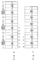
- a shared sense amplifier configuration is known to reduce the area of a memory chip.
- a sense amplifier 62 constituted of sensing NMOS transistors and restoring PMOS transistors is provided between two sub arrays 61, and the two sub arrays 61 are selectively connected to the single sense amplifier 62 by controlling data transfer transistors in response to control signals Xfer1 and Xfer2, thereby time-divisionally using the single sense amplifier 62 by the two sub arrays 61.
- the configuration shown in FIG. 5 is more efficient than that shown in FIG. 6. More specifically, since the configuration of FIG. 6 includes contiguous sense amplifiers 72, the number of sense amplifiers in FIG. 6 is larger than that of sense amplifiers in FIG. 5, with the result that the chip area is increased and the configuration efficiency is lowered.
- the configuration as shown in FIG. 7 is obtained. More specifically, half the sub arrays 71 (A, B, C) or 71 (a, b, c) are activated, and data is latched by sense amplifiers 72 excluding a sense amplifier at one end of the configuration in FIG. 7, thereby increasing the number of sense amplifiers which stand by for access while latching the data.
- the sub arrays A and a cannot be divided into different banks since the foregoing condition (1) is not satisfied, nor can be the sub arrays a and B since they share a sense amplifier with each other and thus the condition (1) is not satisfied. It is thus understood that in the shared sense amplifier configuration as shown in FIG. 7, the sub arrays cannot be divided into banks.
- the sub arrays have to be separate in order to group the sub arrays into banks in the shared sense amplifier configuration. This lessens the effect of reduction in chip area due to high configuration efficiency which is advantageous to the shared sense amplifier configuration.
- the configuration shown in FIG. 8 employs a vertical surface mounting package (VSMP) in which all I/O pads 76 for inputting/outputting data having bit number corresponding to a bit configuration are collectively provided on one side of the array of the sub arrays and vertically mounted on a memory chip mounting printed circuit board.
- VSMP vertical surface mounting package
- a lead frame inside the package and wires on the circuit board can be shortened and thus data can be transferred at high speed.
- data lines 73 are provided for each of sub arrays 71 and connected to a data buffer (DQ buffer) 74 corresponding to each of the sub arrays.
- DQ buffer data buffer
- Each multiplexer (MPX) 75 is connected to corresponding data buffers 74 of the banks 1 and 2. The number of multiplexers 75 is equal to that of I/O pads 76.
- both the sub arrays 71 and sense amplifiers 72 are increased in number. This may cause a problem, taking into consideration that the sub arrays are likely to increase in number as the DRAM increases in capacity as described above.
- the problem is that data paths for connecting the DQ buffers 74 and multiplexers 75 are lengthened thereby to prevent data from being transferred at high speed in the memory chip.
- the conventional DRAM has the problem wherein a long data path prevents high-speed data transfer if the cache memories are increased in number and divided into plural banks in order to enhance the hit rate of the cache memories in the shared sense amplifier configuration with high configuration efficiency.
- the enhancement of the hit rate and the high-speed data transfer are incompatible to achieve the shared sense amplifier configuration or the sense amplifier cache memory system in a small area.
- An object of the invention is to provide a dynamic type memory capable of enhancing the hit rate of a cache memory and increasing the speed of data transfer by shortening data paths formed in a chip when a shared sense amplifier configuration and a sense amplifier cache memory system are achieved in a small area.
- Another object of the invention is to provide a high-performance, low-cost dynamic type memory having the advantages of both a shared sense amplifier configuration and a sense amplifier cache memory system.
- a dynamic type memory of a shared sense amplifier structure comprising:
- the dynamic type memory of the present invention may further comprise a plurality of data buffer circuits provided to the sub arrays of the memory blocks, each for amplifying data transferred via a corresponding data line of a corresponding sub array, the data buffer circuits being in an arrangement in the first direction on the semiconductor chip and a plurality of multiplexers being in an arrangement in the first direction on the semiconductor chip, the arrangement of the multiplexers being between the arrangement of the input/output pads and the arrangement of the data buffer circuits which are closest to input/output pads, each of the multiplexers being connected to a corresponding sub array of each of the banks.
- the dynamic type memory of the present invention may comprise a plurality of data buffer and multiplexer circuits arranged in the first direction on the semiconductor chip, an arrangement of the data buffer and multiplexer circuits being between the arrangement of the input/output pads and that of the memory blocks which are closest to the input/output pads.
- those of the data lines which are provided to the sub arrays of one of the memory blocks have a size larger than that of those of the data lines which are provided for sub arrays of another of the memory blocks which is nearer to the input/output pads than the one memory block.
- each of the sense amplifiers is shared in a time division manner by two of the sub arrays adjacent thereto.
- a plurality of memory blocks each having a shared sense amplifier configuration are arranged as a plurality of banks along the second direction of a memory chip which is perpendicular to the first direction in which sub arrays and sense amplifiers are arranged alternately.
- a sense amplifier cache memory system in which the sense amplifiers are used as cache memories, can be adopted.
- each of multiplexers is connected to a plurality of data lines of corresponding sub arrays of different banks, data of the banks can be multiplexed and data of each bank can be read out independently.
- each bank has data paths connected to all I/O pads, the hit rate of the cache memories can be increased.
- the sense amplifiers perform their operations (e.g., sensing, latching and equalizing operations) at the same timing, while the sense amplifiers, which correspond to the sub arrays standing by for access, are set to keep holding the data sensed so far.
- the capacity of the cache memories can thus be increased, as can be the hit rate thereof.
- the multiplexers and I/O pads are arranged locally on one side of the memory chip in the first direction which is perpendicular to the second direction.
- the sub arrays and sense amplifiers are arranged alternately, one of the sense amplifiers is located at each end of each memory block, and one sense amplifier interposed between two sub arrays is time-divisionally used by the two sub arrays.
- the DRAM having such an efficient shared sense amplifier configuration can thus be achieved in a small area.
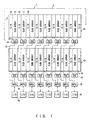
- FIG. 1 shows an example of the arrangement of sub arrays 11, sense amplifiers (SA) 12, data buffers (DQ) 14, multiplexers (MPX) 15 and input/output pads (I/O) 16 of a memory cell array of a memory chip 1 of a DRAM according to a first embodiment of the present invention
- FIG. 2 shows part of the arrangement of FIG. 1 which includes two sub arrays 11, one sense amplifier 12 and one data buffer 14.
- a plurality of memory blocks 10 (two memory blocks 10 in this embodiment) of a shared sense amplifier configuration each include sub arrays 11 and sense amplifiers 12 which are arranged alternately in a first direction X of the chip 1 (in the lateral direction of FIG. 1). It is sense amplifiers 12 that located at both ends of each memory block 10.
- One sense amplifier 12 is used time-divisionally by two sub arrays 11 interposing the sense amplifier 12, which means the shared sense amplifier configuration.
- Such a configuration has been described above with reference to, for example, FIG. 4.
- the memory blocks 10 are arranged in a second direction Y (in the longitudinal direction) which is perpendicular to the first direction X.
- the DRAM is controlled as a plurality of banks (two banks in this embodiment) corresponding to the blocks.
- the banks are designated (selected) in response to a decoded signal of a bank address.
- each of the sub arrays 11 includes an array of dynamic memory cells MC arranged in matrix, a plurality of word lines WL (WL1, WL2, ...) connected to the memory cells MC on their respective rows, and a plurality of bit lines BL (BL1, BL2, ...) connected to the memory cells MC on their respective columns.
- Each of the word lines WL is selected by a row decoder 21 for decoding a row address
- each of the bit lines BL is selected by a column selection circuit (not shown) in response to a decoded signal output from a column decoder (not shown) for decoding a column address, with the result that one memory cell MC is selected.
- the memory cells MC of each sub array are therefore selected by sequentially selecting the row and column addresses.
- the sense amplifiers 12 which are operated at the same timing, amplifies the potential read out from memory cells MC of a selected row in the accessed sub array 11, and continue holding the data sensed so far (standing by to output) in the sub array 11 standing by for access. In this way, the sense amplifiers are employed as cache memories.
- a circuit has only to be formed to allow control signals /SAN and SAP for activating the sense amplifier circuits, as shown in FIG. 4, to remain activated.
- a plurality of data lines 13 are formed for the corresponding sense amplifiers 12 in parallel with the second direction Y of the memory chip 1 and used to transfer that data of a selected column which is stored in the sense amplifiers 12.
- data lines 13 of two different banks 10 as shown in FIG. 1 data lines 13 extending from the bank located far from the I/O pads 16, pass over the sense amplifiers 12 of the other bank located near to the I/O pads.
- the I/O pads 16 are common to the plural banks 10 and arranged on one side of the memory cell array in parallel with the first direction X of the memory chip. Data is input/output to/from the I/O pads 16 and their corresponding sub arrays 11 through the data lines 13.
- the data buffers (DQ buffers) 14 are arranged on one side of each block, which is near to the I/O pads 16, in parallel with the first direction X, so as to correspond to the sub arrays 11. These data buffers are inserted between the data lines 13 and I/O pads 16 to amplify data supplied from the corresponding sub arrays 11.
- the multiplexers 15 are arranged between the data buffers 14 and I/O pads 16 in parallel with the first direction X and each connected to the corresponding two data buffers 14 of the two banks 10 through the corresponding data lines 13. These multiplexers selectively extract data from the banks 10.
- the multiplexers 15 are each constituted by switching elements (e.g., MOS transistors) connected in series between the corresponding I/O pad 16 and data lines 13 of the different banks, with the result that data can be input/output selectively to/from the different banks.
- switching elements e.g., MOS transistors
- each of the sub arrays includes a register 26 for holding a row address (corresponding to a selected row) and a comparator 27 for comparing the row address held in the register 26 with a new row address.
- the comparator 27 compares the two row addresses described above. If they coincide with each other, the comparator outputs a hit signal, and data of a column corresponding to a column address is output without any operation of the rows. If they do not coincide, it outputs a mishit signal, and the register 26, word line and sense amplifier are reset and then the new row address is set in the register circuit 26. The rows are operated in accordance with the new row address held in the register circuit 26.
- the sub array is supplied again with an access request and a row address to determine whether a hit or a mishit occurs. In the case of hit, data of a column corresponding to a column address is read out without any operation of the rows.
- the above operations are performed in the plurality of sub arrays 11 by sequentially supplying the sub arrays 11 with an access request. In each of the sub arrays 11, only the row in which a mishit occurs can be selected and thus all the rows need not be selected every time a mishit occurs.
- the data lines 13 of the bank located far from the I/O pads 16 are longer than those of the bank located near to the I/O pads. It is thus desirable that the former data lines be made thicker than the latter ones in order to make the wiring resistances of the former and latter data lines 13 approximately equal to each other by suppressing an increase in the wiring resistance of the former data lines.
- the memory blocks 10 each having the shared sense amplifier configuration are arranged as two banks in the direction Y which is perpendicular to the direction X in which the sub arrays 11 and sense amplifiers 12 are arranged alternately.
- sense amplifier cache memory system using the sense amplifiers as cache memories can be applied to the DRAM.
- each bank Since one multiplexer 15 is connected to two data buffers 14 of the corresponding sub arrays 11 of the different two banks, data of these banks can be multiplexed and data of each bank can be read independently. Since, moreover, each bank has data paths connected to all the I/O pads 16, the hit rate of the cache memories can be increased.
- the sense amplifiers 12 perform their operations (e.g., sensing, latching and equalizing operations) at the same timing, and the sense amplifiers 12, which correspond to the sub arrays standing by for access, are set to keep holding the data sensed so far. Therefore, the capacity of the cache memories can be increased, as can be the hit rate thereof.
- the multiplexers 15 and I/O pads 16 are arranged on one side of the memory cell array in parallel with the first direction X.
- the sub arrays 11 and sense amplifiers 12 are arranged alternately to constitute a memory block, one of the sense amplifiers is located at each end of the memory block, and one sense amplifier 12 interposed between two sub arrays 11 is time-divisionally used by the two sub arrays 11. Since the DRAM of the first embodiment has such an efficient shared sense amplifier configuration, it can be achieved in a small area.
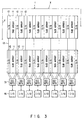
- FIG. 3 shows an example of the arrangement of sub arrays 11, sense amplifiers 12, data buffers/ multiplexers 31 and input/output pads 16 of a memory chip of a DRAM according to a second embodiment of the present invention.
- the second embodiment differs from the first embodiment in that the data buffers/multiplexers 31 are employed in place of the data buffers 14 and multiplexers 14 of the first embodiment.
- the data buffers/multiplexers 31 are interposed between the I/O pads 16 and their adjacent memory block 10 and arranged in parallel with the first direction X of the memory chip.
- Each of the data buffers/multiplexers 31 is connected to a plurality of data lines 13 of the corresponding sub arrays 11 of different banks to selectively amplify and extract the data output from the banks.
- the elements other than the data buffers/multiplexers 31 are the same as those of the first embodiment and thus denoted by the same reference numerals.
- a plurality of memory blocks 10 (two memory blocks 10 in this embodiment) of a shared sense amplifier configuration each include sub arrays 11 and sense amplifiers 12 which are arranged alternately in a first direction X of the chip 1 (in the lateral direction of FIG. 3). It is sense amplifiers 12 that located at both ends of each memory block 10.
- One sense amplifier 12 is used time-divisionally by two sub arrays 11 interposing the sense amplifier 12, which means the shared sense amplifier configuration.
- the memory blocks 10 are arranged in a second direction Y (in the longitudinal direction) which is perpendicular to the first direction X.
- the DRAM is controlled as a plurality of banks (two banks in this embodiment) corresponding to the blocks.
- the banks are designated (selected) in response to a decoded signal of a bank address.
- each of the sub arrays 11 includes an array of dynamic memory cells MC arranged in matrix, a plurality of word lines WL (WL1, WL2, ...) connected to the memory cells MC on their respective rows, and a plurality of bit lines BL (BL1, BL2, ...) connected to the memory cells MC on their respective columns.
- Each of the word lines WL is selected by a row decoder 21 for decoding a row address
- each of the bit lines BL is selected by a column selection circuit (not shown) in response to a decoded signal output from a column decoder (not shown) for decoding a column address, with the result that one memory cell MC is selected.
- the memory cells MC of each sub array are therefore selected by sequentially selecting the row and column addresses.
- the sense amplifiers 12 which are operated at the same timing, amplifies the potential read out from memory cells MC of a selected row in the accessed sub array 11, and continue holding the data sensed so far (standing by to output) in the sub array 11 standing by for access. In this way, the sense amplifiers are employed as cache memories.
- a circuit has only to be formed to allow control signals /SAN and SAP for activating the sense amplifier circuits, as shown in FIG. 4, to remain activated.
- a plurality of data lines 13 are formed for the corresponding sense amplifiers 12 in parallel with the second direction Y of the memory chip 1 and used to transfer that data of a selected column which is stored in the sense amplifiers 12.
- data lines 13 of two different banks 10 as shown in FIG. 3, data lines 13 extending from the bank located far from the I/O pads 16, pass over the sense amplifiers 12 of the other bank located near to the I/O pads.
- FIG. 9 is a partial pattern view of the arrangement of FIG. 3, in which the data line 13 extending from the far located bank and the data line 13 extending from the near located bank are formed on the same insulation film. The data line 13 extending from the far located bank passes over the sense amplifier region of the near located bank.
- the I/O pads 16 are common to the plural banks 10 and arranged on one side of the memory cell array in parallel with the first direction X of the memory chip. Data is input/output to/from the I/O pads 16 and their corresponding sub arrays 11 through the data lines 13.
- the data buffers/multiplexers 31 are interposed between the I/O pads 16 and their adjacent memory block 10 and arranged in parallel with the first direction X of the memory chip. Each of the data buffers/ multiplexers 31 is connected to a plurality of data lines 13 of the corresponding sub arrays 11 of different banks to selectively amplify and extract the data output from the banks.
- the multiplexer portions are each constituted by switching elements (e.g., MOS transistors) connected in series between the corresponding I/O pad 16 and data lines 13 of the different banks, with the result that data can be input/output selectively to/from the different banks.
- switching elements e.g., MOS transistors
- each of the sub arrays includes a register 26 for holding a row address (corresponding to a selected row) and a comparator 27 for comparing the row address held in the register 26 with a new row address.
- the comparator 27 compares the two row addresses described above. If they coincide with each other, the comparator outputs a hit signal, and data of a column corresponding to a column address is output without any operation of the rows. If they do not coincide, it outputs a mishit signal, and the register 26, word line and sense amplifier are reset and then the new row address is set in the register circuit 26. The rows are operated in accordance with the new row address held in the register circuit 26.
- the sub array is supplied again with an access request and a row address to determine whether a hit or a mishit occurs. In the case of hit, data of a column corresponding to a column address is read out without any operation of the rows.
- the above operations are performed in the plurality of sub arrays 11 by sequentially supplying the sub arrays 11 with an access request. In each of the sub arrays 11, only the row in which a mishit occurs can be selected and thus all the rows need not be selected every time a mishit occurs.
- the memory blocks 10 each having the shared sense amplifier configuration are arranged as two banks in the direction Y which is perpendicular to the direction X in which the sub arrays 11 and sense amplifiers 12 are arranged alternately.
- sense amplifier cache memory system using the sense amplifiers as cache memories can be applied to the DRAM.
- each bank Since one data buffer/multiplexer 31 is connected to the corresponding sub arrays 11 of the different two banks, data of these banks can be multiplexed and data of each bank can be read independently. Sine, moreover, each bank has data paths connected to all the I/O pads 16, the hit rate of the cache memories can be increased.
- the sense amplifiers 12 perform their operations (e.g., sensing, latching and equalizing operations) at the same timing, and the sense amplifiers 12, which correspond to the sub arrays standing by for access, are set to keep holding the data sensed so far. Therefore, the capacity of the cache memories can be increased, as can be the hit rate thereof.
- the data buffers/multiplexers 31 and I/O pads 16 are arranged on one side of the memory cell array in parallel with the first direction X.
- the sub arrays 11 and sense amplifiers 12 are arranged alternately to constitute a memory block, one of the sense amplifiers is located at each end of the memory block, and one sense amplifier 12 interposed between two sub arrays 11 is time-divisionally used by the two sub arrays 11. Since the DRAM of the first embodiment has such an efficient shared sense amplifier configuration, it can be achieved in a small area.
- the data lines 13 of the bank located far from the I/O pads 16 are longer than those of the bank located near to the I/O pads. It is thus desirable that the former data lines be made thicker than the latter ones in order to make the wiring resistances of the former and latter data lines 13 approximately equal to each other by suppressing an increase in the wiring resistance of the former data lines.
- the DRAM of the second embodiment is able to perform the same operation as that of the DRAM of the first embodiment and produce substantially the same advantage as that of the DRAM of the first embodiment.
- the DRAM of the present invention when a small-area or small-sized memory chip having both a shared sense amplifier configuration and a sense amplifier cache memory system is formed, the hit rate of the cache memories can be increased, and data can be transferred at high speed by shortening the data paths in the memory chip.
- the DRAM of the present invention is capable of having the advantages of both the shared sense amplifier configuration and sense amplifier cache memory system.
Landscapes
- Engineering & Computer Science (AREA)
- Computer Hardware Design (AREA)
- Microelectronics & Electronic Packaging (AREA)
- Theoretical Computer Science (AREA)
- Databases & Information Systems (AREA)
- Physics & Mathematics (AREA)
- General Engineering & Computer Science (AREA)
- General Physics & Mathematics (AREA)
- Dram (AREA)
- Semiconductor Memories (AREA)
Priority Applications (1)
| Application Number | Priority Date | Filing Date | Title |
|---|---|---|---|
| EP00124224A EP1081711B1 (en) | 1994-09-22 | 1995-09-20 | Dynamic type memory |
Applications Claiming Priority (3)
| Application Number | Priority Date | Filing Date | Title |
|---|---|---|---|
| JP22763994 | 1994-09-22 | ||
| JP227639/94 | 1994-09-22 | ||
| JP06227639A JP3135795B2 (ja) | 1994-09-22 | 1994-09-22 | ダイナミック型メモリ |
Related Child Applications (1)
| Application Number | Title | Priority Date | Filing Date |
|---|---|---|---|
| EP00124224A Division EP1081711B1 (en) | 1994-09-22 | 1995-09-20 | Dynamic type memory |
Publications (2)
| Publication Number | Publication Date |
|---|---|
| EP0704847A1 EP0704847A1 (en) | 1996-04-03 |
| EP0704847B1 true EP0704847B1 (en) | 2001-05-30 |
Family
ID=16864038
Family Applications (2)
| Application Number | Title | Priority Date | Filing Date |
|---|---|---|---|
| EP95114797A Expired - Lifetime EP0704847B1 (en) | 1994-09-22 | 1995-09-20 | Dynamic type memory having shared sense amplifiers |
| EP00124224A Expired - Lifetime EP1081711B1 (en) | 1994-09-22 | 1995-09-20 | Dynamic type memory |
Family Applications After (1)
| Application Number | Title | Priority Date | Filing Date |
|---|---|---|---|
| EP00124224A Expired - Lifetime EP1081711B1 (en) | 1994-09-22 | 1995-09-20 | Dynamic type memory |
Country Status (7)
| Country | Link |
|---|---|
| US (1) | US5586078A (enExample) |
| EP (2) | EP0704847B1 (enExample) |
| JP (1) | JP3135795B2 (enExample) |
| KR (1) | KR0184091B1 (enExample) |
| CN (1) | CN1134016C (enExample) |
| DE (2) | DE69536100D1 (enExample) |
| TW (1) | TW303522B (enExample) |
Families Citing this family (45)
| Publication number | Priority date | Publication date | Assignee | Title |
|---|---|---|---|---|
| US5901105A (en) * | 1995-04-05 | 1999-05-04 | Ong; Adrian E | Dynamic random access memory having decoding circuitry for partial memory blocks |
| US5787267A (en) * | 1995-06-07 | 1998-07-28 | Monolithic System Technology, Inc. | Caching method and circuit for a memory system with circuit module architecture |
| JPH09161476A (ja) | 1995-10-04 | 1997-06-20 | Toshiba Corp | 半導体メモリ及びそのテスト回路、並びにデ−タ転送システム |
| JP3277108B2 (ja) * | 1995-10-31 | 2002-04-22 | インターナショナル・ビジネス・マシーンズ・コーポレーション | Dramアレイ |
| TW348266B (en) | 1996-03-11 | 1998-12-21 | Toshiba Co Ltd | Semiconductor memory device |
| JP3477018B2 (ja) * | 1996-03-11 | 2003-12-10 | 株式会社東芝 | 半導体記憶装置 |
| JPH09288888A (ja) | 1996-04-22 | 1997-11-04 | Mitsubishi Electric Corp | 半導体記憶装置 |
| JP2927344B2 (ja) * | 1996-08-09 | 1999-07-28 | 日本電気株式会社 | 半導体記憶回路 |
| US6044433A (en) * | 1996-08-09 | 2000-03-28 | Micron Technology, Inc. | DRAM cache |
| JP3280867B2 (ja) * | 1996-10-03 | 2002-05-13 | シャープ株式会社 | 半導体記憶装置 |
| US6134172A (en) * | 1996-12-26 | 2000-10-17 | Rambus Inc. | Apparatus for sharing sense amplifiers between memory banks |
| US6075743A (en) * | 1996-12-26 | 2000-06-13 | Rambus Inc. | Method and apparatus for sharing sense amplifiers between memory banks |
| DE69731307T2 (de) * | 1996-12-26 | 2006-03-09 | Rambus Inc., Los Altos | Verfahren und anordnung zur gemeinsamen verwendung von leseverstärkern zwischen speicherbänken |
| KR100242998B1 (ko) * | 1996-12-30 | 2000-02-01 | 김영환 | 잡음특성을 개선한 셀 어레이 및 센스앰프의 구조 |
| US5774408A (en) * | 1997-01-28 | 1998-06-30 | Micron Technology, Inc. | DRAM architecture with combined sense amplifier pitch |
| US5995437A (en) * | 1997-06-02 | 1999-11-30 | Townsend And Townsend And Crew Llp | Semiconductor memory and method of accessing memory arrays |
| US6084816A (en) * | 1998-04-16 | 2000-07-04 | Kabushiki Kaisha Toshiba | Semiconductor memory device |
| US6141286A (en) * | 1998-08-21 | 2000-10-31 | Micron Technology, Inc. | Embedded DRAM architecture with local data drivers and programmable number of data read and data write lines |
| US6442666B1 (en) * | 1999-01-28 | 2002-08-27 | Infineon Technologies Ag | Techniques for improving memory access in a virtual memory system |
| KR100363079B1 (ko) * | 1999-02-01 | 2002-11-30 | 삼성전자 주식회사 | 이웃한 메모리 뱅크들에 의해 입출력 센스앰프가 공유된 멀티 뱅크 메모리장치 |
| US6118717A (en) * | 1999-07-15 | 2000-09-12 | Stmicroelectronics, Inc. | Method and apparatus for loading directly onto bit lines in a dynamic random access memory |
| TW434538B (en) * | 1999-07-28 | 2001-05-16 | Sunplus Technology Co Ltd | Cache data access memory structure |
| KR100339428B1 (ko) * | 1999-09-07 | 2002-05-31 | 박종섭 | 불휘발성 강유전체 메모리의 셀 블록 구조 |
| TW519646B (en) | 2000-03-13 | 2003-02-01 | Infineon Technologies Ag | Write-read-amplifier for a DRAM-memory cell as well as DRAM-memory and method to evaluate the DRAM-memory cells of said DRAM-memory |
| US7215595B2 (en) * | 2003-11-26 | 2007-05-08 | Infineon Technologies Ag | Memory device and method using a sense amplifier as a cache |
| US7050351B2 (en) * | 2003-12-30 | 2006-05-23 | Intel Corporation | Method and apparatus for multiple row caches per bank |
| US6990036B2 (en) | 2003-12-30 | 2006-01-24 | Intel Corporation | Method and apparatus for multiple row caches per bank |
| KR100533977B1 (ko) * | 2004-05-06 | 2005-12-07 | 주식회사 하이닉스반도체 | 셀영역의 면적을 감소시킨 반도체 메모리 장치 |
| KR101149816B1 (ko) * | 2004-05-28 | 2012-05-25 | 삼성전자주식회사 | 캐쉬 메모리의 캐쉬 히트 로직 |
| DE102004059723B4 (de) * | 2004-12-11 | 2010-02-25 | Qimonda Ag | Speicherbauelement mit neuer Anordnung der Bitleitungen |
| KR100735527B1 (ko) * | 2006-02-13 | 2007-07-04 | 삼성전자주식회사 | 2개의 패드 행을 포함하는 반도체 메모리 장치 |
| JP2009009633A (ja) * | 2007-06-27 | 2009-01-15 | Elpida Memory Inc | 半導体記憶装置 |
| JP5743045B2 (ja) * | 2008-07-16 | 2015-07-01 | ピーエスフォー ルクスコ エスエイアールエルPS4 Luxco S.a.r.l. | 半導体記憶装置及び半導体記憶装置におけるメモリアクセス方法 |
| JP2011146094A (ja) | 2010-01-14 | 2011-07-28 | Renesas Electronics Corp | 半導体集積回路 |
| US10276230B2 (en) | 2016-08-31 | 2019-04-30 | Micron Technology, Inc. | Memory arrays |
| US10355002B2 (en) | 2016-08-31 | 2019-07-16 | Micron Technology, Inc. | Memory cells, methods of forming an array of two transistor-one capacitor memory cells, and methods used in fabricating integrated circuitry |
| KR102208380B1 (ko) | 2016-08-31 | 2021-01-28 | 마이크론 테크놀로지, 인크 | 메모리 셀들 및 메모리 어레이들 |
| WO2018044456A1 (en) | 2016-08-31 | 2018-03-08 | Micron Technology, Inc. | Memory cells and memory arrays |
| US10115438B2 (en) | 2016-08-31 | 2018-10-30 | Micron Technology, Inc. | Sense amplifier constructions |
| CN109155312B (zh) | 2016-08-31 | 2023-05-02 | 美光科技公司 | 存储器单元及存储器阵列 |
| KR102171724B1 (ko) | 2016-08-31 | 2020-10-30 | 마이크론 테크놀로지, 인크 | 메모리 셀 및 메모리 어레이 |
| WO2018132250A1 (en) | 2017-01-12 | 2018-07-19 | Micron Technology, Inc. | Memory cells, arrays of two transistor-one capacitor memory cells, methods of forming an array of two transistor-one capacitor memory cells, and methods used in fabricating integrated circuitry |
| EP3676835A4 (en) * | 2017-08-29 | 2020-08-19 | Micron Technology, Inc. | MEMORY CIRCUITS |
| KR102792404B1 (ko) * | 2021-08-17 | 2025-04-04 | 연세대학교 산학협력단 | Ram 메모리에 기반한 pim 연산 장치 및 ram 메모리에 기반한 pim 연산 방법 |
| GB2634496A (en) * | 2023-10-04 | 2025-04-16 | Ibm | Banked sense amplifier circuit for a memory core and a memory core complex |
Family Cites Families (6)
| Publication number | Priority date | Publication date | Assignee | Title |
|---|---|---|---|---|
| JPH0814985B2 (ja) | 1989-06-06 | 1996-02-14 | 富士通株式会社 | 半導体記憶装置 |
| ATE101746T1 (de) * | 1989-11-24 | 1994-03-15 | Siemens Ag | Halbleiterspeicher. |
| EP0454998B1 (en) * | 1990-03-28 | 1995-11-08 | Nec Corporation | Semiconductor memory device |
| JPH05274879A (ja) * | 1992-03-26 | 1993-10-22 | Nec Corp | 半導体装置 |
| US5384745A (en) * | 1992-04-27 | 1995-01-24 | Mitsubishi Denki Kabushiki Kaisha | Synchronous semiconductor memory device |
| KR970004460B1 (ko) | 1992-06-30 | 1997-03-27 | 니뽄 덴끼 가부시끼가이샤 | 반도체 메모리 회로 |
-
1994
- 1994-09-22 JP JP06227639A patent/JP3135795B2/ja not_active Expired - Fee Related
-
1995
- 1995-09-14 US US08/528,306 patent/US5586078A/en not_active Expired - Lifetime
- 1995-09-20 DE DE69536100T patent/DE69536100D1/de not_active Expired - Lifetime
- 1995-09-20 EP EP95114797A patent/EP0704847B1/en not_active Expired - Lifetime
- 1995-09-20 DE DE69521095T patent/DE69521095T2/de not_active Expired - Lifetime
- 1995-09-20 EP EP00124224A patent/EP1081711B1/en not_active Expired - Lifetime
- 1995-09-21 CN CNB951165518A patent/CN1134016C/zh not_active Expired - Fee Related
- 1995-09-22 KR KR1019950031300A patent/KR0184091B1/ko not_active Expired - Lifetime
- 1995-10-28 TW TW084111414A patent/TW303522B/zh not_active IP Right Cessation
Also Published As
| Publication number | Publication date |
|---|---|
| DE69536100D1 (de) | 2010-10-14 |
| EP1081711A2 (en) | 2001-03-07 |
| CN1134016C (zh) | 2004-01-07 |
| EP0704847A1 (en) | 1996-04-03 |
| KR960012008A (ko) | 1996-04-20 |
| DE69521095T2 (de) | 2001-10-25 |
| JPH0896571A (ja) | 1996-04-12 |
| CN1142115A (zh) | 1997-02-05 |
| TW303522B (enExample) | 1997-04-21 |
| EP1081711B1 (en) | 2010-09-01 |
| JP3135795B2 (ja) | 2001-02-19 |
| EP1081711A3 (en) | 2008-04-09 |
| DE69521095D1 (de) | 2001-07-05 |
| US5586078A (en) | 1996-12-17 |
| KR0184091B1 (ko) | 1999-04-15 |
Similar Documents
| Publication | Publication Date | Title |
|---|---|---|
| EP0704847B1 (en) | Dynamic type memory having shared sense amplifiers | |
| USRE37427E1 (en) | Dynamic type memory | |
| US6442098B1 (en) | High performance multi-bank compact synchronous DRAM architecture | |
| EP0905705B1 (en) | Space-efficient semiconductor memory having hierarchical column select line architecture | |
| US8769234B2 (en) | Memory modules and devices supporting configurable data widths | |
| US6862229B2 (en) | Physically alternating sense amplifier activation | |
| JP3202580B2 (ja) | 半導体メモリ装置 | |
| US5783480A (en) | Layout method for semiconductor memory device obtaining high bandwidth and signal line | |
| JPH08172169A (ja) | 半導体記憶装置 | |
| US6125070A (en) | Semiconductor memory device having multiple global I/O line pairs | |
| US6459647B1 (en) | Split-bank architecture for high performance SDRAMs | |
| JP3741153B2 (ja) | 高速動作のための共有dram i/oデータバス | |
| US6055202A (en) | Multi-bank architecture for a wide I/O DRAM | |
| US5831912A (en) | Semiconductor memory having space-efficient layout | |
| JPH04302894A (ja) | 分散されたアドレス解読およびタイミング制御機能を有するメモリ | |
| KR100552886B1 (ko) | 고속 인터리빙 성능을 가진 집적 dram | |
| US5657265A (en) | Semiconductor memory device having circuit array structure for fast operation | |
| US6487101B1 (en) | Use of search lines as global bitlines in a cam design | |
| US6023428A (en) | Integrated circuit device having a memory array with segmented bit lines and method of operation | |
| US7359252B2 (en) | Memory data bus structure and method of transferring information with plural memory banks | |
| JP3278646B2 (ja) | 半導体装置 | |
| KR100314129B1 (ko) | 데이터 입출력 라인의 부하를 줄이는 뱅크 구성방법 및 데이터입출력 라인 배치방법으로 구현된 반도체 메모리 장치 | |
| EP0913831B1 (en) | Space-efficient master data line (MDQ) switch placement | |
| KR100380023B1 (ko) | 단변 방향의 칩 사이즈를 줄일 수 있는 반도체메모리장치 | |
| HK1019813A (en) | Space-efficient master data line (mdq) switch placement |
Legal Events
| Date | Code | Title | Description |
|---|---|---|---|
| PUAI | Public reference made under article 153(3) epc to a published international application that has entered the european phase |
Free format text: ORIGINAL CODE: 0009012 |
|
| 17P | Request for examination filed |
Effective date: 19950920 |
|
| AK | Designated contracting states |
Kind code of ref document: A1 Designated state(s): DE FR GB |
|
| 17Q | First examination report despatched |
Effective date: 19990701 |
|
| GRAG | Despatch of communication of intention to grant |
Free format text: ORIGINAL CODE: EPIDOS AGRA |
|
| GRAG | Despatch of communication of intention to grant |
Free format text: ORIGINAL CODE: EPIDOS AGRA |
|
| GRAH | Despatch of communication of intention to grant a patent |
Free format text: ORIGINAL CODE: EPIDOS IGRA |
|
| GRAH | Despatch of communication of intention to grant a patent |
Free format text: ORIGINAL CODE: EPIDOS IGRA |
|
| GRAA | (expected) grant |
Free format text: ORIGINAL CODE: 0009210 |
|
| AK | Designated contracting states |
Kind code of ref document: B1 Designated state(s): DE FR GB |
|
| PG25 | Lapsed in a contracting state [announced via postgrant information from national office to epo] |
Ref country code: FR Free format text: LAPSE BECAUSE OF FAILURE TO SUBMIT A TRANSLATION OF THE DESCRIPTION OR TO PAY THE FEE WITHIN THE PRESCRIBED TIME-LIMIT Effective date: 20010530 |
|
| REF | Corresponds to: |
Ref document number: 69521095 Country of ref document: DE Date of ref document: 20010705 |
|
| PGFP | Annual fee paid to national office [announced via postgrant information from national office to epo] |
Ref country code: FR Payment date: 20010911 Year of fee payment: 7 |
|
| EN | Fr: translation not filed | ||
| REG | Reference to a national code |
Ref country code: GB Ref legal event code: IF02 |
|
| PLBE | No opposition filed within time limit |
Free format text: ORIGINAL CODE: 0009261 |
|
| STAA | Information on the status of an ep patent application or granted ep patent |
Free format text: STATUS: NO OPPOSITION FILED WITHIN TIME LIMIT |
|
| 26N | No opposition filed | ||
| PGFP | Annual fee paid to national office [announced via postgrant information from national office to epo] |
Ref country code: GB Payment date: 20100916 Year of fee payment: 16 |
|
| GBPC | Gb: european patent ceased through non-payment of renewal fee |
Effective date: 20110920 |
|
| PG25 | Lapsed in a contracting state [announced via postgrant information from national office to epo] |
Ref country code: GB Free format text: LAPSE BECAUSE OF NON-PAYMENT OF DUE FEES Effective date: 20110920 |
|
| PGFP | Annual fee paid to national office [announced via postgrant information from national office to epo] |
Ref country code: DE Payment date: 20120912 Year of fee payment: 18 |
|
| REG | Reference to a national code |
Ref country code: DE Ref legal event code: R119 Ref document number: 69521095 Country of ref document: DE Effective date: 20140401 |
|
| PG25 | Lapsed in a contracting state [announced via postgrant information from national office to epo] |
Ref country code: DE Free format text: LAPSE BECAUSE OF NON-PAYMENT OF DUE FEES Effective date: 20140401 |