EP0905705B1 - Space-efficient semiconductor memory having hierarchical column select line architecture - Google Patents
Space-efficient semiconductor memory having hierarchical column select line architecture Download PDFInfo
- Publication number
- EP0905705B1 EP0905705B1 EP98114245A EP98114245A EP0905705B1 EP 0905705 B1 EP0905705 B1 EP 0905705B1 EP 98114245 A EP98114245 A EP 98114245A EP 98114245 A EP98114245 A EP 98114245A EP 0905705 B1 EP0905705 B1 EP 0905705B1
- Authority
- EP
- European Patent Office
- Prior art keywords
- bit line
- bank
- switches
- global
- line switch
- Prior art date
- Legal status (The legal status is an assumption and is not a legal conclusion. Google has not performed a legal analysis and makes no representation as to the accuracy of the status listed.)
- Expired - Lifetime
Links
- 239000004065 semiconductor Substances 0.000 title claims description 27
- 230000015654 memory Effects 0.000 claims description 52
- 230000000295 complement effect Effects 0.000 claims description 27
- 238000009792 diffusion process Methods 0.000 claims description 23
- 239000004020 conductor Substances 0.000 claims description 19
- 230000005669 field effect Effects 0.000 claims description 2
- 238000010586 diagram Methods 0.000 description 5
- 238000003491 array Methods 0.000 description 2
- 230000004044 response Effects 0.000 description 2
- 230000003213 activating effect Effects 0.000 description 1
- 230000001413 cellular effect Effects 0.000 description 1
- 230000002093 peripheral effect Effects 0.000 description 1
Images


Classifications
-
- G—PHYSICS
- G11—INFORMATION STORAGE
- G11C—STATIC STORES
- G11C11/00—Digital stores characterised by the use of particular electric or magnetic storage elements; Storage elements therefor
- G11C11/21—Digital stores characterised by the use of particular electric or magnetic storage elements; Storage elements therefor using electric elements
- G11C11/34—Digital stores characterised by the use of particular electric or magnetic storage elements; Storage elements therefor using electric elements using semiconductor devices
- G11C11/40—Digital stores characterised by the use of particular electric or magnetic storage elements; Storage elements therefor using electric elements using semiconductor devices using transistors
- G11C11/401—Digital stores characterised by the use of particular electric or magnetic storage elements; Storage elements therefor using electric elements using semiconductor devices using transistors forming cells needing refreshing or charge regeneration, i.e. dynamic cells
- G11C11/4063—Auxiliary circuits, e.g. for addressing, decoding, driving, writing, sensing or timing
- G11C11/407—Auxiliary circuits, e.g. for addressing, decoding, driving, writing, sensing or timing for memory cells of the field-effect type
-
- G—PHYSICS
- G11—INFORMATION STORAGE
- G11C—STATIC STORES
- G11C8/00—Arrangements for selecting an address in a digital store
- G11C8/10—Decoders
-
- G—PHYSICS
- G11—INFORMATION STORAGE
- G11C—STATIC STORES
- G11C11/00—Digital stores characterised by the use of particular electric or magnetic storage elements; Storage elements therefor
- G11C11/21—Digital stores characterised by the use of particular electric or magnetic storage elements; Storage elements therefor using electric elements
- G11C11/34—Digital stores characterised by the use of particular electric or magnetic storage elements; Storage elements therefor using electric elements using semiconductor devices
- G11C11/40—Digital stores characterised by the use of particular electric or magnetic storage elements; Storage elements therefor using electric elements using semiconductor devices using transistors
- G11C11/401—Digital stores characterised by the use of particular electric or magnetic storage elements; Storage elements therefor using electric elements using semiconductor devices using transistors forming cells needing refreshing or charge regeneration, i.e. dynamic cells
- G11C11/4063—Auxiliary circuits, e.g. for addressing, decoding, driving, writing, sensing or timing
- G11C11/407—Auxiliary circuits, e.g. for addressing, decoding, driving, writing, sensing or timing for memory cells of the field-effect type
- G11C11/408—Address circuits
- G11C11/4087—Address decoders, e.g. bit - or word line decoders; Multiple line decoders
Definitions
- the present invention relates generally to semiconductor memories such as dynamic random access memories (DRAMs). More specifically, this invention relates to a multi-bank semiconductor memory having a hierarchical architecture for column select lines and data lines.
- DRAMs dynamic random access memories
- Contemporary high density DRAMs typically employ several memory subarrays on the chip, where each subarray is associated with a sense amplifier bank for amplifying the signals stored in the respective cells.
- each subarray is associated with a sense amplifier bank for amplifying the signals stored in the respective cells.
- most, if not all, commercially available DRAMs are incapable of performing read and write operations the different subarrays of a common unit on the chip in overlapping time intervals. Such capability would be desirable in order to increase the overall speed of information storage and retrieval to/from the chip.
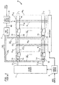
- FIG. 1 is a simplified block diagram and layout of one conventional multi-subarray DRAM architecture.
- DRAM 10 employs a single column decoder 9 in conjunction with two memory cell subarrays MAa and MAb. While only two subarrays are shown for clarity of illustration, state of the art DRAMs typically utilize four or more subarrays.
- a subarray is associated with a sense amplifier bank. Input addresses are applied to an address buffer 8, which splits up each address into a column address supplied to column decoder 9 and a row address supplied to row decoder 7.
- column decoder 9 Based on the column address, e.g., an eight bit address, column decoder 9 activates one of N column select lines, CSL 1 -CSL N , each corresponding to a common column of both subarrays MAa and MAb.
- Each column select line such as CSL 1 is applied to the gates of a pair of FET bit line switches, e.g. 11a and 13a in column C 1 of MAa.
- Column select line CSL 1 extends across MAa and connects to the gates of FET bit switches 11b and 13b in column C 1 of subarray MAb. Extension across the subarray MAa is typically facilitated by fabricating the column select lines in a different vertical layer than the bit lines.
- one of the word lines WL i is activated to turn on the access transistors within the memory cells MC in the corresponding row R i .
- FIG. 1 The configuration shown in FIG. 1 is known as a folded bit line configuration, which employs bit line pairs of true and complementary bit lines running side by side on the same side of the associated sense amplifier.
- Bit switches such as 13a and 11a have their sources connected to corresponding true and complementary bit lines BL 1a and BL 1 a , respectively, of the corresponding column.
- Each one of N sense amplifiers for each subarray e.g. SA 1a to SA Na for array MAa, amplifies a differential voltage between the true and complementary bit lines of the corresponding column during a read operation.
- a true local data line LDQa connects to the drains of each bit switch 13a in bank MAa.
- a complementary local data line LDQa connects to the drains of each bit switch 11a.
- Local data lines LDQb and LDQb are similarly connected to associated bit switches.
- each sense amplifier is typically connected to multiplex switches on both sides of the sense amplifier to thereby provide a "shared" configuration in which cell signals on both sides of the sense amplifier are amplified. If an "open" bit line configuration were used, the true and complementary bit lines of a pair would run on opposite sides of each sense amplifier.
- a master data line (MDQ) switch 15 is employed to switch between subarrays and select one subarray at a time to access cells (write or read data to or from cells).
- the MDQ switch includes suitable logic circuitry which receives the row address from address buffer 8 to determine which array to select. Based on the row address and other control signals, array select switch 15 selects one of the local data lines for memory cell access and switches the data to/from that line from/to a master data line MDQ.
- An input/output buffer 19 acts as a buffer between the MDQ line and external data lines connected to the DRAM.
- EP 0,745,995 discloses a memory including a plurality of banks and switches activated by local column decoders for selectively connecting a selected global bit line and a local bit line. This memory admits of execution of different operations in different blocks at the same time.
- FIG. 2 shows a prior art multi-bank DRAM configuration which allows independent operation of each memory bank.
- the term "bank” refers to a memory array which can essentially be operated independently, i.e. written into while another bank is read from, and vice versa).
- Banks 12a-12d are each disposed adjacent a separate row decoder and each have their associated sense amplifier bank 17 situated adjacent a respective column decoder.
- a main data bus runs in between the upper and lower row decoders on each side, and peripheral circuitry resides in the center of the chip.
- Each memory bank such as 12d may be split up into several subarrays 16 by using additional sense amplifier banks 17' adjacent the respective subarrays 16, and running the column select lines CSL from the column decoder to the bit switches associated with each subarray, as was described in reference to FIG. 1.
- a drawback of the DRAM configuration of FIG.2 is that the additional column decoders employed for the different banks occupy substantial space on the chip, thereby significantly increasing chip size for a given number of memory cells.
- the present disclosure is directed towards a multiple bank semiconductor memory (e.g., DRAM) capable of overlapping write/read operations to/from memory cells of different banks, and having a space efficient layout.
- Chip size is kept small by employing a single column decoder for different banks, and a hierarchical column select line architecture where bit line switches of different columns have a shared active area such as a common source or drain region.
- a semiconductor memory of the present invention includes a plurality of memory cell banks, each having a plurality of rows and columns, with bit lines running in the respective columns to access memory cells therein.
- a column decoder is operative to selectively activate at least one of a plurality of global column select lines in accordance with a column address.
- Each global column select line controls at least one global bit line switch of a memory cell bank, where each global bit line switch is coupled to a data line for the associated memory cell bank.
- a plurality of bank bit line switches are coupled to each global bit line switch, with each bank bit line switch coupled to a bit line of an associated column.
- bit lines are selectively activated in accordance with the column address such that a bit line of a particular column is activated when both a global bit line switch and a bank bit line switch associated with that column are activated.
- At least one bank bit line switch has a shared diffusion region, e.g., a common source or drain region, with at least one of another bank bit line switch or a global bit line switch.
- four bank bit line switches of different columns and one global bit line switch have a common active area (diffusion region) to provide a space-efficient layout.
- the present invention relates to a multiple bank semiconductor memory capable of overlapping write/read operations to/from memory cells of different banks, and having a space efficient layout.
- the invention employs a hierarchical column select line architecture and active area sharing among bit line switches to achieve a compact layout for a multi-bank memory.
- an exemplary embodiment of the invention is described in the context of a DRAM chip. The invention however has broader applications.
- the invention has application in other memory devices such as EDO-DRAM, SDRAM, RAMBUS-DRAM, MDRAM, SRAM, flash RAM, EPROM, EEPROM, mask ROM, or merged DRAM-logic (embedded DRAM).
- the devices are used in, for example, consumer products such as computer systems, cellular phones, personal digital assistants (PDAs), and other electronic products.
- DRAM 40 utilizes a single column decoder 44 for at least two memory cell arrays (banks) MAa and MAb. While only two memory cell banks are shown, column decoder 44 is typically used for four or more banks.
- Each memory cell bank MAa, MAb has memory cells arranged in N columns by M rows, where N and M are each typically a large number.
- the N columns of each memory cell bank are connected to N respective sense amplifiers SA 1 to SA N , each of which amplifies a voltage level read from a selected memory cell in the column in a conventional manner.
- Incoming addresses are applied to an address buffer 52 which splits up each address into a column address and a row address.
- the column address is applied both to column decoder 44 and to bank column select decoders 46a and 46b for banks MAa and MAb, respectively.
- column decoder 44 activates a corresponding one of N/K global column select lines GCSL 1 to GCSL N/K , where K is an integer greater than one. In the embodiment of FIG. 3, K equals four.
- Each global column select line is associated with four columns in this example.
- MDQ switch 49 is responsive to a row input signal to switch the data on a selected local data line to a master data line MDQ, which is connected to a conventional input/output buffer 51 for data transfer to/from the DRAM.
- bank column select (BCS) decoders 46a, 46b are shown in FIG. 3 as separate from column decoder 44, they are preferably integrated with column decoder 44.
- the DRAM may utilize only a single BCS decoder for all of the memory banks MAa, MAb, etc. In this case, the same corresponding BCSL line is activated for each bank. For example, if line BCSL 4a of bank MAa is activated, then line BCSL 4b of bank MAb would be activated, and so forth.
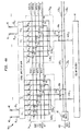
- FIG. 4A is a schematic of a part of DRAM 40 illustrating the hierarchical bit line and hierarchical local data line arrangements.
- each global column select line such as GCSL 1 connects to the gates of a pair of global bit line switches 67a and 68a for memory cell array MAa.
- Global line GCSL 1 also connects to the gates of switches 67b and 68b of bank MAb.
- Global bit line switches 67a, 68a are coupled to a bank bit line (BBL) switch set 34 1a of bank MAa; switches 67b, 68b are coupled to BBL switch set 34 1b of bank MAb, and so forth.
- BBL bank bit line
- Global bit line switch 67a has its source coupled to local data line LDQa of memory array MAa, and its drain coupled to a sub local data line SLDQ 1 .
- Sub local data line SLDQ 1 is coupled to the sources of bank bit line switches 59, 61, 63 and 65, which have their drains coupled to true bit lines BL 1 to BL 4 , respectively.
- the gates of bank bit line switches 59, 61, 63 and 65 are coupled to bank column select lines BCSL 1a to BCSL 4a , respectively.
- a write or read operation can be commenced for a memory cell in column C 2 (or a different column) and row R j of bank MAb.
- a different row address may be supplied to row decoder 48a of MAa than to row decoder 48b of MAb.
- An input R/W signal or signals applied to timing and control circuit 53 controls which bank is to be read from and which is to be written to. If a read from bank MAa and an overlapping write into bank MAb are to be performed, data corruption is prevented by offsetting the timing signals driving the bank bit line switches in bank MAa relative to bank MAb. That is, bank column select decoders 46a and 46b activate the bank bit line switches in the respective banks at different times.
- FIG. 5 An example of this offset timing approach is illustrated in FIG. 5.
- data is written into a memory cell in column C 2 of bank MAa while an overlapping read is performed from column C 3 of bank MAb.
- the GCSL 1 line is raised.
- the BCSL 2a line is brought high, turning on bank bit line switches 61 and 62 to permit data to be written into a cell in column C 2 .
- a precharge operation is commenced at time t 2 for the bin lines of column C 3 by disabling the associated sense amplifier SA 3 and activating the equalization circuit for that column.
- the time interval between times t 3 and t 4 is thus very short, e.g., about 15 nanoseconds.
- the time separating read and write operations of different subarrays is substantially longer, e.g., about 60 nanoseconds.
- the DRAM 40 in FIG. 3 is shown for clarity as having a folded bit line architecture with unshared sense amplifiers.
- a shared sense amplifier configuration is preferable, as shown in FIG. 4B.
- each sense amplifier SA i is used for reading and refresh operations to memory cells located on both sides of the sense amplifier.
- memory bank MAa would consist of a left array MA aL and a right array MP aR on respective left and right sides of the sense amplifier bank.
- latch circuit 54 there resides a pair of multiplex switches 53 1L , 53 2L or 53 1R , 53 2R to select the left or right sides of the bank in response to control signals MUX L or MUX R .
- a control signal CTL P controls the P-latch portion of latch 54 while control signal CTL N , controls the N-latch.
- Equalization circuits EQ L and EQ R are coupled between the MUX switches 53 and the respective left and right sides of the memory bank.
- Memory cells MC in column C i are accessed via bit line BL iL or BL iL in array MA aL , or via bit line BL iR or BL iR in array MA 3R .
- the drains of the associated bank column select switches such as 59 and 61 are connected to the circuit nodes of the latch circuit 54 in between the MUX switches.
- the bank and global column select switches are disposed in a different vertical layer than the sense amplifiers.
- DRAM 40 uses an open bit line architecture, as shown in FIG. 4C.
- the bit line pairs BL i , BL i extend on opposite sides of the sense amplifier SA i . Only one equalization circuit EQ is necessary for the open configuration.
- the drains of the bank column select switches such as 59 and 61 connect to opposite circuit nodes of the latch 54.
- the present invention is also applicable to memory cell arrays with sense amplifiers using reference cells, such as in flash RAM.
- the bit lines are not arranged in true and complementary pairs. Rather, the reference cell within the sense amplifier provides the equalization (reference) voltage that the complementary line would otherwise provide (when accessing cells coupled to the true cells) or that the true bit line would otherwise provide (when accessing cells coupled to the complementary bit lines).
- the bank bit line switches would be connected to opposite sides of the latch 54 for this case as well.
- FIG. 6 there is shown a plan view of an exemplary layout for the bank bit line switches, the global bit line switches, and the bank and global column select lines, for the hierarchical circuit configuration of FIGS. 3 and 4(A-C).
- An important feature of the layout is the active area (AA) sharing between several bit line transistors.
- the active area sharing allows for a highly compact design which thereby enables the hierarchical architecture to be implemented with low or minimal area penalty.
- active area is shared among all "true" bit line switches of each bank bit line switch set 34 i and the associated global bit line transistor 67 for the set.
- Active area is also preferably shared among all "complementary" bit line switches of each switch set 34 i and the associated global bit line transistor 68 for that set.
- each bit line switch set 34 1 -34 (N/K) is essentially the same.
- active area AA1 is shared among bank bit line transistors 59, 61, 63 and 65, each of which has its drain coupled to a true bank bit line BL 1 , BL 2 , BL 3 and BL 4 , respectively. Active area AA1 is also shared with global bit line transistor 67.
- the gate conductor of a transistor with legend "ii" is designated as G ii
- the drain region is designated as D ii
- the electrical contact from bit line to drain is designated as DC ii
- the electrical contact from a bank column select line to the gate conductor of transistor "ii" is designated as GN ii .
- Each drain region has a drain to bit line contact, e.g., contact DC 61 for device 61.
- the portion of active area AA 1 adjacent the U-shaped gate conductor G 59 is the source region of transistor 59, and the region on the other side of gate G 59 , designated as D 59 , is the drain region of device 59.
- Contact GN 59 connects gate G 59 to bank column select switch BCSL 1 ; drain contact DC 59 connects drain region D 59 to bit line BL 1 , and so forth. All connections correspond to the schematic diagram of FIG. 4A.
- the active area AA 1 is the equivalent of the sub local data line SLDQ 1 of FIG.4A; AA 2 corresponds to STDQ 1 ; AA 3 corresponds to SLDQ 2 ; and AA 4 corresponds to SLDQ 2 .
- each active area AA 1 -AA 4 serves as the source region for four bank bit line transistors of a set, and as the drain region for one global bit line transistor.
- the bottom portion of active area AA 1 comprises the source regions of transistors 59, 61, 63 and 65, whereas the top portion of active area AA 1 serves as the drain region for the global bit line transistor 67 coupled to bit line switch set 34 1 .
- Gate conductor G 67 separates active area AA 1 with the source S 67 of device 67.
- Global column select line GCSL 1 runs generally perpendicular to the bank column select lines and connects to gate conductor G 57 via gate contact GN 57 .
- GCSL 1 also connects to gate conductor G 68 of device 68 via gate contact GN 68 .
- the source region S 67 of device 67 connects to local data line LDQ through source contact SC 67 .
- Source region S 68 of device 68 connects through source contact SC 68 to local data line LDQ .
- global column select line GCSL 2 runs generally perpendicular to the bank column select lines and connects to the gates of the global bit switches 67 and 68 associated with bank switch set 34 2 .
- Active area AA 2 is shared among bank bit line transistors 60, 62, 64 and 66 and with global bit line transistor 68. As such, active area AA 2 encompasses the source regions of devices 60, 62, 64 and 66 and the drain region of device 68. Similarly, active area AA 3 encompasses the source regions of transistors 59, 61, 63 and 65 of bit line switch set 34 2 , and active area AA 4 encompasses the source regions of devices 60, 62, 64 and 66 of switch set 34 2 .
- Bit line switches that have their gates coupled together may share a continuous gate conductor.
- gates G 61 and G 62 are formed as one continuous line, as are gate conductors G 65 and G 66 .
- local bit line transistor pairs 59, 60 do not share a continuous gate conductor, but are electrically connected through the bank column select line.
- Bank column select line BCSL 1a of FIG. 4 is comprised of an upper line BCSL 1u and a lower line BCSL 1l as depicted in FIG. 6, where the upper line BCSL 1u and lower line BCSL 1l are periodically connected at several points along the length of the memory cell array.
- bank column select line BCSL 3a of FIG. 4 is comprised of the upper and lower line BCSL 3u and BCSL 3l of FIG. 6, which are periodically connected. Connection between these upper and lower column select lines is typically realized by an electrical interconnection of each line to a connecting conductor on another vertically spaced layer.
- the active area sharing concept of the present invention is not limited to the sharing of active areas of five transistors, nor to active area sharing of all the true or complementary bit line switches of each bank bit line switch set.
- diffusion region sharing of at least three transistors of each bank bit line set is preferred in order to achieve compactness in the design and conserve as much space as possible.
- DRAM 40' differs the above-discussed DRAM 40 in that four local data lines are used for each memory cell bank, the bank bit line switches are grouped differently, and a different grouping for the global bit line switches are used.
- each global column select line GCSL i is coupled to the gates of four global bit line switches 101-104 of each memory cell array such as MAa and MAb.
- the drains of switches 101, 102, 103 and 104 are coupled to local data lines LDQ 1 , LDQ 1 , LDQ 2 and LDQ 2 , each of which connects to an MDQ switch 109.
- MDQ switch 109 receives control signals from the row decoder or associated control circuitry to switch a selected LDQ line to a master data line MDQ.
- the MDQ line is buffered by I/O buffer 111.
- Bank bit line switch set 84 i1 is comprised of bank bit line switches 85-88 which have their gates coupled to bank CSL line BCSL 1 , and bank bit line switches 89-92 which have their gates coupled to line BCSL 2 .
- bank bit line switch set 84 i2 consists of bank bit line switches 93-96 which have their gates tied to BCSL3, and bank bit line switches 97-100 which have their gates tied to line BCSL4.
- the bank column select lines for each bank are selectively activated by a bank column select decoder 46a or 46b as was the case for DRAM 40 of FIG. 2.
- each global column select line GSCL i controls four global CSL switches, which are in turn coupled to sixteen bank CSL switches, the number of global column select lines is half the number for the configuration of FIG. 2.
- column decoder 44' which is modified from decoder 44 of DRAM 40, activates line GCSLi whenever the column address corresponds to one of the associated sixteen local column select lines.
- DRAM 40' Operation of DRAM 40' is similar to that described above for DRAM 40.
- MDQ switch 109 switches between eight local data lines as opposed to four as in DRAM 40.
- the designs of the bank column select decoders 46a, 46b are modified to activate the correct bank bit line switches corresponding to the column address.
- the layout for the bank bit line switches and global bit line switches of DRAM 44' may be similar to that for DRAM 40, preferably with sets of at least four bank bit line switches in proximity to one another sharing diffusion regions (active areas) to conserve space, and with one or more of the global bit line switches sharing diffusion regions with the bank bit line switches.
Landscapes
- Engineering & Computer Science (AREA)
- Microelectronics & Electronic Packaging (AREA)
- Computer Hardware Design (AREA)
- Dram (AREA)
- Semiconductor Memories (AREA)
- Static Random-Access Memory (AREA)
Description
Claims (20)
- A semiconductor memory (40), comprising:wherein at least one said bank bit line switch (341a-34(N/K)a, 341b-34(N/K)b) has a shared diffusion region (AA) with at least one of another bank bit line switch (341a-34(N/K)a, 341b-34(N/K)b) or a global bit line switch (67a, 68a, 67b, 68b).a plurality of memory cell banks (MAa, MAb), each having a plurality of rows and a plurality of columns (C1-CN), with bit lines running in the respective columns (C1-CN) to access memory cells therein;a column decoder (44) operative to selectively activate at least one of a plurality of global column select lines (GCSL1-GCSLN/K) in accordance with a column address, each global column select line (GCSL1-GCSLN/K) controlling at least one global bit line switch (67a, 68a, 67b, 68b) of a memory cell bank (MAa, MAb), each global bit line switch (67a, 68a, 67b, 68b) coupled to a data line (LDQb, LDQb/) for the associated memory cell bank;a plurality of bank bit line switches (341a-34(N/K)a, 341b-34(N/K)b) coupled to each global bit line switch (67a, 68a, 67b, 68b), with each bank bit line switch (341a-34(N/K)a, 341b-34(N/K)b) coupled to a bit line of an associated column (C1-CN) ;said bit lines being selectively activated in accordance with said column address such that a bit line of a particular column (C1-CN) is activated when both a global bit line switch (67a, 68a, 67b, 68b) and a bank bit line switch (341a-34(N/K)a, 341b-34 (N/K)b) associated with that column (C1-CN) are activated;
- The semiconductor memory (40) of claim 1, wherein each column (C1-CN) includes a true bank bit line switch coupled to a true bit line and a complementary bank bit line switch coupled to a complementary bit line, and at least four bank bit line switches (341a-34(N/K)a, 341b-34(N/K)b) and one global bit line switch (67a, 68a, 67b, 68b) have a shared diffusion region (AA).
- The semiconductor memory (40) of claim 2, wherein at least four bank bit line switches (341a-34(N/K)a, 341b-34(N/K)b) coupled to true bit lines of different columns (C1-CN) and one global bit line switch (67a, 68a, 67b, 68b) have a shared diffusion region (AA).
- The semiconductor memory (40) of claim 2 wherein said bank (341a-34(N/K)a, 341b-34(N/K)b) and global bit line switches (67a, 68a, 67b, 68b) are field effect transistors and said diffusion region (AA) comprises a source region for said bank bit line switches (341a-34(N/K)a, 341b-34(N/K)b) and a drain region for said global bit line switches (67a, 68a, 67b, 68b),
- The semiconductor memory (40) of claim 1 wherein said memory (40) comprises a dynamic random access memory.
- The semiconductor memory (40) of claim 1 wherein the number of bank column select lines (BCSLa, BCSLb) for each bank (MAa, MAb) equals N/K, where K is an integer greater than one.
- The semiconductor memory (40) of claim 1 wherein the bank bit line switches (341a-34(N/K)a, 341b-34(N/K)b) are coupled to respective sense amplifiers (SA1-SAN) each connected to bit lines on both sides of the sense amplifier (SA1-SAN) in a shared configuration, the bit lines arranged in a folded bit line configuration.
- The semiconductor memory (40) of claim 1 wherein the bank bit line switches (341a-34(N/K)a, 341b-34(N/K)b) are coupled to respective sense amplifiers (SA1-SAN) each connected to bit lines on both sides thereof in an open bit line arrangement.
- The semiconductor memory (40) of claim 1 wherein:bank bit line switches (341a-34(N/K)a, 341b-34(N/K)b) coupled to bit lines of different columns (C1-CN) and one global bit line switch (67a, 68a, 67b, 68b) have a shared diffusion region (AA);said shared diffusion region (AA) of said bank bit line switches (341a-34(N/K)a, 341b-34 (N/K)b) and said one global bit line switch (67a, 68a, 67b, 68b) is a centralized shared diffusion region (AA) of a larger active area; andsaid global (67a, 68a, 67b, 68b) and bank bit line switches (341a-34N/K)a, 341b-34(N/K)b) each include a gate conductor having an L-shaped portion, such that the gate conductors of the bank bit line switches (341a-34(N/K)a, 341b-34(N/K)b) of different columns (C1-CN) and the one global bit line switch (67a, 68a, 67b, 68b) separate said centralized region from one of a source or drain region of each respective bank bit line switch (341a-34(N/K)a, 341b-34(N/K)b) and the one global bit line switch (67a, 68a, 67b, 68b).
- The semiconductor memory (40) of claim 9 wherein four bank bit line switches (341a-34(N/K)a, 341b-34(N/K)b) share said centralized shared diffusion region.
- The semiconductor memory (40) of claim 9, wherein said bank bit line switches (341a-34(N/K)a, 341b-34(N/K)b) comprise true bank bit line switches and complementary bank bit line switches, said true and complementary bank bit line switches being arranged in bank bit line switch sets such that the true bank bit line switches of a given set are coupled to a true global bit line switch associated with the given set and the complementary bank bit line switches of the given set are coupled to a complementary global bit line switch associated with the given set; and
the true bank bit line switches of the given set and the associated true global bit line switch share a first said centralized shared diffusion region, and the complementary bank bit line switches of the given set and the associated complementary global bit line switch share a second said centralized shared diffusion region. - The semiconductor memory (40) of claim 11 wherein a gate conductor of at least one true bank bit line switch or the given set is shared with a gate conductor of a corresponding complementary bank bit line switch.
- The semiconductor memory (40) of claim 12 wherein the gate conductor shared between the true bank bit line switch and the complementary bank bit line switch of the given set is U-shaped and extends between the first and second centralized diffusion regions.
- The semiconductor memory (40) of claim 1, wherein said each memory cell bank includes plural bank column select lines (BcsL1a-BCSL4a, BCSL1b-BCSL4b), each coupled to bank bit line switches (341a-34(N/K)a, 341b-34(N/K)b) of different columns (C1-CN) and controlling switching states thereof.
- The semiconductor memory (40) of claim 14 wherein four local bit line switches of different columns (C1-CN) and at least one global bit line switch (67a, 68a, 67b, 68b) have a shared diffusion region (AA).
- The semiconductor memory of claim 14 wherein the memory comprises a dynamic random access memory.
- The semiconductor memory (40) of claim 14 wherein each memory cell bank (MAa, MAb) includes folded bit lines.
- The semiconductor memory (40) of claim 14 wherein each memory cell bank (MAa, MAb) includes open bit lines.
- The semiconductor memory (40) of claim 14, wherein said bank bit line switches (341a-34(N/K)a, 341b-34(N/k)b) are coupled to bit lines of different columns (C1-CN) and an associated global bit line switch (67a, 68a, 67b, 68b) have a shared diffusion region (AA);
said shared diffusion region (AA) of said bank bit line switches (341a-34(N/K)a, 341b-34(N/K)b) and said associated global bit line switch (67a, 68a, 67b, 68b) is a centralized shared diffusion region of a larger active area; and,
said global (67a, 68a, 67b, 68b) and bank bit line switches (341a-34(N/K)a, 341b-34(N/K)b) each include a gate conductor having an L-shaped portion, such that the gate conductors of the bank bit line switches (341a-34(N/K)a, 341b-34 (N/K)b) of different columns (C1-CN) and the associated global bit line switch (67a, 68a, 67b, 68b) separate said centralized region from one of a source or drain region of each respective bank bit line switch (341a-34(N/K)a, 341b-34(N/K)b) and the associated global bit line switch (67a, 68a, 67b, 68b). - The semiconductor memory (40) of claim 19, wherein said bank bit line switches (341a-34(N/K)a, 341b-34(N/K)b) comprise true bank bit line switches and complementary bank bit line switches, said true and complementary bank bit line switches being arranged in bank bit line switch sets such that the true bank bit line switches of a given set are coupled to a true global bit line switch associated with the given set and the complementary bank bit line switches of the given set are coupled to a complementary global bit line switch associated with the given set;
the true bank bit line switches of the given set and the associated true global bit line switch share a first said centralized shared diffusion region, and the complementary bank bit line switches of the given set and the associated complementary global bit line switch share a second said centralized shared diffusion region;
wherein a gate conductor for at least one true bank bit line switch of the given set is shared with a gate conductor of a corresponding complementary bank bit line switch.
Applications Claiming Priority (2)
| Application Number | Priority Date | Filing Date | Title |
|---|---|---|---|
| US940861 | 1997-09-29 | ||
| US08/940,861 US5923605A (en) | 1997-09-29 | 1997-09-29 | Space-efficient semiconductor memory having hierarchical column select line architecture |
Publications (3)
| Publication Number | Publication Date |
|---|---|
| EP0905705A2 EP0905705A2 (en) | 1999-03-31 |
| EP0905705A3 EP0905705A3 (en) | 1999-07-28 |
| EP0905705B1 true EP0905705B1 (en) | 2005-04-06 |
Family
ID=25475548
Family Applications (1)
| Application Number | Title | Priority Date | Filing Date |
|---|---|---|---|
| EP98114245A Expired - Lifetime EP0905705B1 (en) | 1997-09-29 | 1998-07-30 | Space-efficient semiconductor memory having hierarchical column select line architecture |
Country Status (7)
| Country | Link |
|---|---|
| US (1) | US5923605A (en) |
| EP (1) | EP0905705B1 (en) |
| JP (1) | JPH11185468A (en) |
| KR (1) | KR100574242B1 (en) |
| CN (1) | CN1174428C (en) |
| DE (1) | DE69829618T2 (en) |
| TW (1) | TW411478B (en) |
Families Citing this family (47)
| Publication number | Priority date | Publication date | Assignee | Title |
|---|---|---|---|---|
| US6172935B1 (en) | 1997-04-25 | 2001-01-09 | Micron Technology, Inc. | Synchronous dynamic random access memory device |
| JP3252895B2 (en) * | 1997-11-07 | 2002-02-04 | 日本電気株式会社 | Semiconductor memory device and driving method thereof |
| KR100351048B1 (en) * | 1999-04-27 | 2002-09-09 | 삼성전자 주식회사 | Column selection circuit capable of minimising load of data input/output line and semiconductor memory device having the same |
| US6137746A (en) * | 1999-07-28 | 2000-10-24 | Alliance Semiconductor Corporation | High performance random access memory with multiple local I/O lines |
| GB2363231B (en) * | 1999-09-24 | 2002-05-08 | Clearspeed Technology Ltd | Memory devices |
| KR100352766B1 (en) * | 2000-03-07 | 2002-09-16 | 삼성전자 주식회사 | Layout structure and method of column path in semiconductor memory device |
| US6327215B1 (en) | 2000-09-28 | 2001-12-04 | Vanguard International Semiconductor Corporation | Local bit switch decode circuit and method |
| JP3937752B2 (en) | 2001-05-10 | 2007-06-27 | 株式会社日立製作所 | Mobile phones and base stations |
| US20030206479A1 (en) * | 2001-06-21 | 2003-11-06 | Chun Shiah | High area efficient data line architecture |
| US6606275B2 (en) * | 2001-08-23 | 2003-08-12 | Jeng-Jye Shau | High performance semiconductor memory devices |
| KR100403348B1 (en) * | 2001-10-08 | 2003-11-01 | 주식회사 하이닉스반도체 | Circuit for bit line selection having hierarchical structure |
| US6768692B2 (en) * | 2002-07-29 | 2004-07-27 | International Business Machines Corporation | Multiple subarray DRAM having a single shared sense amplifier |
| KR20040017468A (en) * | 2002-08-21 | 2004-02-27 | 엘지전자 주식회사 | Mobile for display dual clock and method for setting dual clock |
| US7054178B1 (en) * | 2002-09-06 | 2006-05-30 | Etron Technology, Inc. | Datapath architecture for high area efficiency |
| JP2004326974A (en) * | 2003-04-25 | 2004-11-18 | Toshiba Corp | Semiconductor integrated circuit device and IC card |
| JP4989847B2 (en) * | 2003-12-12 | 2012-08-01 | 株式会社半導体エネルギー研究所 | Semiconductor device |
| CN1661721B (en) * | 2004-02-26 | 2010-09-15 | 钰创科技股份有限公司 | Data line structure with high-level local performance |
| US7082075B2 (en) * | 2004-03-18 | 2006-07-25 | Micron Technology, Inc. | Memory device and method having banks of different sizes |
| JP4470159B2 (en) * | 2004-06-03 | 2010-06-02 | エルピーダメモリ株式会社 | Semiconductor memory device with high density arrangement of pair transistors |
| KR100630694B1 (en) * | 2004-08-03 | 2006-10-02 | 삼성전자주식회사 | Memory device with single-bit bus structure using current mode signaling |
| JP2006134469A (en) * | 2004-11-05 | 2006-05-25 | Elpida Memory Inc | Semiconductor memory device |
| US7516264B2 (en) * | 2005-02-09 | 2009-04-07 | International Business Machines Corporation | Programmable bank/timer address folding in memory devices |
| US7893813B2 (en) * | 2005-07-28 | 2011-02-22 | Intermec Ip Corp. | Automatic data collection device, method and article |
| US7310257B2 (en) * | 2005-11-10 | 2007-12-18 | Micron Technology, Inc. | Local digit line architecture and method for memory devices having multi-bit or low capacitance memory cells |
| US9141557B2 (en) * | 2006-12-08 | 2015-09-22 | Ashish A. Pandya | Dynamic random access memory (DRAM) that comprises a programmable intelligent search memory (PRISM) and a cryptography processing engine |
| DE102007012902B3 (en) * | 2007-03-19 | 2008-07-10 | Qimonda Ag | Bit line pair and amplifier arrangement for use in e.g. dynamic RAM, of computer system, has read amplifiers whose positions along bit line direction are selected such that coupling paths have same coupling characteristics |
| US7869246B2 (en) | 2007-05-25 | 2011-01-11 | Marvell World Trade Ltd. | Bit line decoder architecture for NOR-type memory array |
| KR100878313B1 (en) * | 2007-06-11 | 2009-01-14 | 주식회사 하이닉스반도체 | Data input / output line control circuit and semiconductor integrated circuit including the same |
| US20090013148A1 (en) * | 2007-07-03 | 2009-01-08 | Micron Technology, Inc. | Block addressing for parallel memory arrays |
| KR20090029140A (en) * | 2007-09-17 | 2009-03-20 | 삼성전자주식회사 | Method and system for providing standard time in mobile broadcasting service |
| US8159898B2 (en) * | 2008-01-18 | 2012-04-17 | Hynix Semiconductor Inc. | Architecture of highly integrated semiconductor memory device |
| US8194492B2 (en) | 2008-04-08 | 2012-06-05 | Samsung Electronics Co., Ltd. | Variable resistance memory device and system |
| KR101476773B1 (en) | 2008-04-08 | 2014-12-29 | 삼성전자주식회사 | A semiconductor memory device and a memory system including a variable resistance memory device |
| KR20090117189A (en) * | 2008-05-09 | 2009-11-12 | 삼성전자주식회사 | Semiconductor Memory Device with Efficient Core Structure for Multi-Write |
| US7692975B2 (en) * | 2008-05-09 | 2010-04-06 | Micron Technology, Inc. | System and method for mitigating reverse bias leakage |
| US7907468B2 (en) | 2008-05-28 | 2011-03-15 | Micron Technology, Inc. | Memory device having data paths permitting array/port consolidation and swapping |
| US8482981B2 (en) * | 2008-05-30 | 2013-07-09 | Qimonda Ag | Method of forming an integrated circuit with NAND flash array segments and intra array multiplexers and corresponding integrated circuit with NAND flash array segments and intra array multiplexers |
| CN101452740B (en) * | 2008-12-26 | 2013-11-06 | 复旦大学 | Column decoder for simultaneously selecting multiple bit lines |
| US9116781B2 (en) * | 2011-10-17 | 2015-08-25 | Rambus Inc. | Memory controller and memory device command protocol |
| US8693236B2 (en) | 2011-12-09 | 2014-04-08 | Gsi Technology, Inc. | Systems and methods of sectioned bit line memory arrays, including hierarchical and/or other features |
| US8593860B2 (en) | 2011-12-09 | 2013-11-26 | Gsi Technology, Inc. | Systems and methods of sectioned bit line memory arrays |
| KR102193444B1 (en) | 2014-04-28 | 2020-12-21 | 삼성전자주식회사 | Semiconductor memory device and memory system including the same |
| US9275686B2 (en) | 2014-05-28 | 2016-03-01 | Avago Technologies General Ip (Singapore) Pte. Ltd. | Memory banks with shared input/output circuitry |
| US11443795B2 (en) * | 2017-07-12 | 2022-09-13 | Ambiq Micro, Inc. | SRAM with address dependent power usage |
| US12376291B2 (en) | 2020-09-04 | 2025-07-29 | Changxin Memory Technologies, Inc. | Semiconductor device including shared sense amplification circuit group |
| CN114155896B (en) * | 2020-09-04 | 2024-03-29 | 长鑫存储技术有限公司 | Semiconductor device with a semiconductor device having a plurality of semiconductor chips |
| KR20240069475A (en) | 2022-11-11 | 2024-05-20 | 삼성전자주식회사 | Memory device |
Family Cites Families (8)
| Publication number | Priority date | Publication date | Assignee | Title |
|---|---|---|---|---|
| US4006469A (en) * | 1975-12-16 | 1977-02-01 | International Business Machines Corporation | Data storage cell with transistors operating at different threshold voltages |
| JPH07130163A (en) * | 1993-11-01 | 1995-05-19 | Matsushita Electron Corp | Semiconductor memory |
| US5535172A (en) * | 1995-02-28 | 1996-07-09 | Alliance Semiconductor Corporation | Dual-port random access memory having reduced architecture |
| EP0745995B1 (en) * | 1995-05-05 | 2001-04-11 | STMicroelectronics S.r.l. | Nonvolatile, in particular flash-EEPROM, memory device |
| KR0142962B1 (en) * | 1995-05-12 | 1998-08-17 | 김광호 | Semiconductor memory apparatus |
| KR100350700B1 (en) * | 1995-12-27 | 2003-01-24 | 삼성전자 주식회사 | Semiconductor memory apparatus |
| KR100211760B1 (en) * | 1995-12-28 | 1999-08-02 | 윤종용 | Data I / O Path Control Circuit of Semiconductor Memory Device with Multi-Bank Structure |
| US5822268A (en) * | 1997-09-11 | 1998-10-13 | International Business Machines Corporation | Hierarchical column select line architecture for multi-bank DRAMs |
-
1997
- 1997-09-29 US US08/940,861 patent/US5923605A/en not_active Expired - Lifetime
-
1998
- 1998-07-30 DE DE69829618T patent/DE69829618T2/en not_active Expired - Lifetime
- 1998-07-30 EP EP98114245A patent/EP0905705B1/en not_active Expired - Lifetime
- 1998-08-20 KR KR1019980033718A patent/KR100574242B1/en not_active Expired - Fee Related
- 1998-09-21 CN CNB981196705A patent/CN1174428C/en not_active Expired - Fee Related
- 1998-09-25 TW TW087115989A patent/TW411478B/en active
- 1998-09-28 JP JP10273949A patent/JPH11185468A/en active Pending
Also Published As
| Publication number | Publication date |
|---|---|
| EP0905705A2 (en) | 1999-03-31 |
| EP0905705A3 (en) | 1999-07-28 |
| DE69829618T2 (en) | 2006-04-27 |
| KR100574242B1 (en) | 2006-07-21 |
| JPH11185468A (en) | 1999-07-09 |
| TW411478B (en) | 2000-11-11 |
| US5923605A (en) | 1999-07-13 |
| DE69829618D1 (en) | 2005-05-12 |
| CN1174428C (en) | 2004-11-03 |
| KR19990029329A (en) | 1999-04-26 |
| CN1215893A (en) | 1999-05-05 |
Similar Documents
| Publication | Publication Date | Title |
|---|---|---|
| EP0905705B1 (en) | Space-efficient semiconductor memory having hierarchical column select line architecture | |
| EP0924709B1 (en) | Semiconductor memory | |
| US5822268A (en) | Hierarchical column select line architecture for multi-bank DRAMs | |
| US5748547A (en) | High performance semiconductor memory devices having multiple dimension bit lines | |
| US6122217A (en) | Multi-bank memory input/output line selection | |
| US6862229B2 (en) | Physically alternating sense amplifier activation | |
| US8218386B2 (en) | Embedded memory databus architecture | |
| US6108229A (en) | High performance embedded semiconductor memory device with multiple dimension first-level bit-lines | |
| US5949732A (en) | Method of structuring a multi-bank DRAM into a hierarchical column select line architecture | |
| US6504745B2 (en) | High performance erasable programmable read-only memory (EPROM) devices with multiple dimension first-level bit lines | |
| US4888732A (en) | Dynamic random access memory having open bit line architecture | |
| JP2000150820A (en) | Semiconductor storage device | |
| US6023428A (en) | Integrated circuit device having a memory array with segmented bit lines and method of operation | |
| JP3913451B2 (en) | Semiconductor memory device | |
| EP0902434B1 (en) | Hierarchical column select line architecture for multi-bank drams and method therefor | |
| HK1017127A (en) | Space-efficient semiconductor memory having hierarchical column select line architecture | |
| JPS6364690A (en) | Semiconductor storage device | |
| HK1018534A (en) | Semiconductor memory |
Legal Events
| Date | Code | Title | Description |
|---|---|---|---|
| PUAI | Public reference made under article 153(3) epc to a published international application that has entered the european phase |
Free format text: ORIGINAL CODE: 0009012 |
|
| AK | Designated contracting states |
Kind code of ref document: A2 Designated state(s): DE FR GB IE IT NL |
|
| AX | Request for extension of the european patent |
Free format text: AL;LT;LV;MK;RO;SI |
|
| PUAL | Search report despatched |
Free format text: ORIGINAL CODE: 0009013 |
|
| AK | Designated contracting states |
Kind code of ref document: A3 Designated state(s): AT BE CH CY DE DK ES FI FR GB GR IE IT LI LU MC NL PT SE |
|
| AX | Request for extension of the european patent |
Free format text: AL;LT;LV;MK;RO;SI |
|
| RIC1 | Information provided on ipc code assigned before grant |
Free format text: 6G 11C 8/00 A, 6G 11C 11/408 B, 6H 01L 27/02 B |
|
| 17P | Request for examination filed |
Effective date: 19991007 |
|
| AKX | Designation fees paid |
Free format text: DE FR GB IE IT NL |
|
| RIN1 | Information on inventor provided before grant (corrected) |
Inventor name: HOENIGSCHMID, HEINZ Inventor name: MUELLER, GERHARD |
|
| 17Q | First examination report despatched |
Effective date: 20030605 |
|
| RAP1 | Party data changed (applicant data changed or rights of an application transferred) |
Owner name: INFINEON TECHNOLOGIES AG |
|
| GRAP | Despatch of communication of intention to grant a patent |
Free format text: ORIGINAL CODE: EPIDOSNIGR1 |
|
| GRAS | Grant fee paid |
Free format text: ORIGINAL CODE: EPIDOSNIGR3 |
|
| GRAA | (expected) grant |
Free format text: ORIGINAL CODE: 0009210 |
|
| AK | Designated contracting states |
Kind code of ref document: B1 Designated state(s): DE FR GB IE IT NL |
|
| REG | Reference to a national code |
Ref country code: GB Ref legal event code: FG4D |
|
| REG | Reference to a national code |
Ref country code: IE Ref legal event code: FG4D |
|
| REF | Corresponds to: |
Ref document number: 69829618 Country of ref document: DE Date of ref document: 20050512 Kind code of ref document: P |
|
| PGFP | Annual fee paid to national office [announced via postgrant information from national office to epo] |
Ref country code: NL Payment date: 20050714 Year of fee payment: 8 |
|
| PGFP | Annual fee paid to national office [announced via postgrant information from national office to epo] |
Ref country code: GB Payment date: 20050725 Year of fee payment: 8 |
|
| PLBE | No opposition filed within time limit |
Free format text: ORIGINAL CODE: 0009261 |
|
| STAA | Information on the status of an ep patent application or granted ep patent |
Free format text: STATUS: NO OPPOSITION FILED WITHIN TIME LIMIT |
|
| REG | Reference to a national code |
Ref country code: HK Ref legal event code: WD Ref document number: 1017127 Country of ref document: HK |
|
| ET | Fr: translation filed | ||
| 26N | No opposition filed |
Effective date: 20060110 |
|
| PG25 | Lapsed in a contracting state [announced via postgrant information from national office to epo] |
Ref country code: GB Free format text: LAPSE BECAUSE OF NON-PAYMENT OF DUE FEES Effective date: 20060730 |
|
| PG25 | Lapsed in a contracting state [announced via postgrant information from national office to epo] |
Ref country code: NL Free format text: LAPSE BECAUSE OF NON-PAYMENT OF DUE FEES Effective date: 20070201 |
|
| GBPC | Gb: european patent ceased through non-payment of renewal fee |
Effective date: 20060730 |
|
| NLV4 | Nl: lapsed or anulled due to non-payment of the annual fee |
Effective date: 20070201 |
|
| REG | Reference to a national code |
Ref country code: FR Ref legal event code: TP Owner name: QIMONDA AG,, DE Effective date: 20120123 |
|
| REG | Reference to a national code |
Ref country code: DE Ref legal event code: R081 Ref document number: 69829618 Country of ref document: DE Owner name: POLARIS INNOVATIONS LTD., IE Free format text: FORMER OWNER: QIMONDA AG, 81739 MUENCHEN, DE Ref country code: DE Ref legal event code: R081 Ref document number: 69829618 Country of ref document: DE Owner name: INFINEON TECHNOLOGIES AG, DE Free format text: FORMER OWNER: QIMONDA AG, 81739 MUENCHEN, DE |
|
| REG | Reference to a national code |
Ref country code: FR Ref legal event code: PLFP Year of fee payment: 18 |
|
| REG | Reference to a national code |
Ref country code: DE Ref legal event code: R081 Ref document number: 69829618 Country of ref document: DE Owner name: POLARIS INNOVATIONS LTD., IE Free format text: FORMER OWNER: INFINEON TECHNOLOGIES AG, 85579 NEUBIBERG, DE |
|
| PGFP | Annual fee paid to national office [announced via postgrant information from national office to epo] |
Ref country code: IE Payment date: 20150723 Year of fee payment: 18 |
|
| PGFP | Annual fee paid to national office [announced via postgrant information from national office to epo] |
Ref country code: DE Payment date: 20150930 Year of fee payment: 18 |
|
| REG | Reference to a national code |
Ref country code: FR Ref legal event code: TP Owner name: INFINEON TECHNOLOGIES AG, DE Effective date: 20160212 |
|
| REG | Reference to a national code |
Ref country code: FR Ref legal event code: PLFP Year of fee payment: 19 |
|
| PGFP | Annual fee paid to national office [announced via postgrant information from national office to epo] |
Ref country code: FR Payment date: 20160613 Year of fee payment: 19 |
|
| PGFP | Annual fee paid to national office [announced via postgrant information from national office to epo] |
Ref country code: IT Payment date: 20160720 Year of fee payment: 19 |
|
| REG | Reference to a national code |
Ref country code: DE Ref legal event code: R119 Ref document number: 69829618 Country of ref document: DE |
|
| PG25 | Lapsed in a contracting state [announced via postgrant information from national office to epo] |
Ref country code: DE Free format text: LAPSE BECAUSE OF NON-PAYMENT OF DUE FEES Effective date: 20170201 |
|
| REG | Reference to a national code |
Ref country code: IE Ref legal event code: MM4A |
|
| PG25 | Lapsed in a contracting state [announced via postgrant information from national office to epo] |
Ref country code: IE Free format text: LAPSE BECAUSE OF NON-PAYMENT OF DUE FEES Effective date: 20160730 |
|
| REG | Reference to a national code |
Ref country code: FR Ref legal event code: ST Effective date: 20180330 |
|
| PG25 | Lapsed in a contracting state [announced via postgrant information from national office to epo] |
Ref country code: FR Free format text: LAPSE BECAUSE OF NON-PAYMENT OF DUE FEES Effective date: 20170731 |
|
| PG25 | Lapsed in a contracting state [announced via postgrant information from national office to epo] |
Ref country code: IT Free format text: LAPSE BECAUSE OF NON-PAYMENT OF DUE FEES Effective date: 20170730 |