EP0696827A2 - Connecteur étanché - Google Patents
Connecteur étanché Download PDFInfo
- Publication number
- EP0696827A2 EP0696827A2 EP95305407A EP95305407A EP0696827A2 EP 0696827 A2 EP0696827 A2 EP 0696827A2 EP 95305407 A EP95305407 A EP 95305407A EP 95305407 A EP95305407 A EP 95305407A EP 0696827 A2 EP0696827 A2 EP 0696827A2
- Authority
- EP
- European Patent Office
- Prior art keywords
- plug body
- cavity
- mold resin
- connector housing
- waterproofed
- Prior art date
- Legal status (The legal status is an assumption and is not a legal conclusion. Google has not performed a legal analysis and makes no representation as to the accuracy of the status listed.)
- Granted
Links
Images


Classifications
-
- H—ELECTRICITY
- H01—ELECTRIC ELEMENTS
- H01R—ELECTRICALLY-CONDUCTIVE CONNECTIONS; STRUCTURAL ASSOCIATIONS OF A PLURALITY OF MUTUALLY-INSULATED ELECTRICAL CONNECTING ELEMENTS; COUPLING DEVICES; CURRENT COLLECTORS
- H01R13/00—Details of coupling devices of the kinds covered by groups H01R12/70 or H01R24/00 - H01R33/00
- H01R13/46—Bases; Cases
- H01R13/52—Dustproof, splashproof, drip-proof, waterproof, or flameproof cases
- H01R13/5205—Sealing means between cable and housing, e.g. grommet
- H01R13/5208—Sealing means between cable and housing, e.g. grommet having at least two cable receiving openings
-
- H—ELECTRICITY
- H01—ELECTRIC ELEMENTS
- H01R—ELECTRICALLY-CONDUCTIVE CONNECTIONS; STRUCTURAL ASSOCIATIONS OF A PLURALITY OF MUTUALLY-INSULATED ELECTRICAL CONNECTING ELEMENTS; COUPLING DEVICES; CURRENT COLLECTORS
- H01R13/00—Details of coupling devices of the kinds covered by groups H01R12/70 or H01R24/00 - H01R33/00
- H01R13/46—Bases; Cases
- H01R13/52—Dustproof, splashproof, drip-proof, waterproof, or flameproof cases
- H01R13/521—Sealing between contact members and housing, e.g. sealing insert
-
- H—ELECTRICITY
- H01—ELECTRIC ELEMENTS
- H01R—ELECTRICALLY-CONDUCTIVE CONNECTIONS; STRUCTURAL ASSOCIATIONS OF A PLURALITY OF MUTUALLY-INSULATED ELECTRICAL CONNECTING ELEMENTS; COUPLING DEVICES; CURRENT COLLECTORS
- H01R43/00—Apparatus or processes specially adapted for manufacturing, assembling, maintaining, or repairing of line connectors or current collectors or for joining electric conductors
- H01R43/20—Apparatus or processes specially adapted for manufacturing, assembling, maintaining, or repairing of line connectors or current collectors or for joining electric conductors for assembling or disassembling contact members with insulating base, case or sleeve
- H01R43/24—Assembling by moulding on contact members
Definitions
- This invention relates to a waterproofed connector in which a cable outlet of a connector housing is coupled to a mold resin layer.
- a bayonet molded plug which is a kind of connector having a molded cable outlet is known by, for example, Japanese Utility Model Public Disclosure No. HEI 5-73871 (1993).
- This bayonet molded plug is produced by attaching a pair of bayonet terminals to a mold core made of a thermosetting resin, connecting an end of each core wire of an electrical cable to each terminal, and molding the core wires and mold core by a thermoplastic resin.
- Such structure has the advantage of enhancing waterproofing and impact strength since exposed core wires are covered with a resilient mold resin layer.
- entering paths of water in question are a boundary space between a mold resin layer and a sheath of an electrical cable and a boundary space between the mold resin layer and a connector housing.
- Boundary portions between mold resin parts are likely to have difficulties in adherence to each other when they have a poor appetency and cause a gap therebetween on account of differences of thermal expansion and contraction during a cooling process on molding or a change of temperature while in use. Accordingly, it is necessary to select a resin material which has a good appetency to a sheath resin of the electrical cable and a mold resin of the connector housing and a low coefficient of thermal expansion.
- the sheath resin of the electrical cable is polyethylene, crosslinking polyethylene, or fluorocarbon polymer while the connector housing is made of PBT (polybutylene terephthalate) or PPS (polyphenylene sulfide).
- PBT polybutylene terephthalate
- PPS polyphenylene sulfide
- An object of the present invention is to provide a waterproofed connector in which the outlet of an electrical cable can be molded by resin without causing a problem of mold resin leakage regardless of the structure in which a terminal metal fixture is inserted in a cavity in a connector housing.
- Another object of the present invention is to provide a waterproofed connector which can be produced at a low cost and perform a superior waterproofing function.
- the plug body may be provided with a slit extending from the exterior to each through hole.
- the plug body may be made of a resilient material.
- the plug body may be provided on a front end face with a plurality of vertical ridges, on a rear end with a flange, and on a middle portion with a barrel-like bulged portion.
- a rear end of the connector housing embedded in the mold resin layer may be provided with a plurality of through holes for enhancing a connection between the housing and the layer.
- the waterproofed connector of the present invention it is possible to prevent the mold resin from leaking into an inner part in the cavity upon molding, since the plug body is inserted through the terminal insertion opening in the connector housing into the cavity.
- the plug body In the case of the plug body being made of an elastic material, the plug body can make close contact with the interior of the accommodating chamber, thereby positively preventing the mold resin from leaking into the cavity and enhancing the waterproofing function. Consequently, even if a gap is formed between the connector housing and the mold resin layer and between the electrical cable and the mold resin layer to permit water to enter through the gap into the cavity, the plug body can certainly prevent water from entering into the side of the terminal metal fixture in the cavity.
- Each core wire can be inserted into each through hole through each slit formed in the plug body.
- the leakage of mold resin can certainly be prevented and an injection pressure can be set at high since the elastic plug body fits firmly into the interior of the cavity, thereby maintaining a high level of production efficiency.
- the plug body can perform the waterproofing function, it is possible to prevent water from entering into the side of the terminal metal fixture in the cavity even if a gap is formed between the connector housing and the mold resin layer and between the sheath resin of the electrical cable and the mold resin layer. Accordingly, it is possible to freely select various kinds of material in view of the cost and the like without considering the gap.
- the present invention can reconcile a low cost and a high level of waterproofing.
- a step of passing the core wire into the plug body can be simplified, increasing production efficiency, and reducing the cost of production.
- the waterproofed connector according to the present invention in addition to the structure of the waterproofed connector described above, includes a plug body made of a hard plastic material.
- the exterior of the plug body and the interior of an accommodating chamber for the plug body in the cavity are tapered so that the exterior and interior make close contact with each other.
- the plug body may be divided into a pair of half parts.
- the divided plug body is inserted into the accommodating chamber in the cavity through the terminal insertion opening with the half parts clamping the core wires.
- the divided plug body may include an upper half part and a lower half part.
- the upper and lower half parts may be interconnected by a selfhinge.
- the half parts of the divided plug body may be provided with temporary locking portions for coupling to each other.
- the temporary locking portions may include an engaging hole and an engaging projection or an engaging recess and an engaging pawl.
- a rear end of the connector housing embedded in the mold resin layer may be provided with a plurality of through holes for enhancing a connection between the housing and the layer.
- the waterproofed connector may further comprise a waterproofing seal inserted into an inner part of the cavity through the terminal insertion opening to firmly contact with an interior of the inner part of the cavity.
- the waterproofed connector it is possible to effectively prevent the mold resin from leaking into an inner part in the cavity upon molding since the plug body is inserted into the cavity through the terminal insertion opening in the connector housing. Moreover, since the exterior of the plug body and the interior of the accommodating chamber for the plug body in the cavity are tapered so that the exterior and interior make firm contact with each other, the plug body is pushed to the inner part in the cavity by an injection pressure of the mold resin upon molding, thereby enhancing a firm contact between the plug body and the connector housing and certainly effecting prevention of any leakage of the mold resin.
- the divided plug body can clamp the core wires between the upper and lower half parts so that the core wires pass through the holes, respectively.
- the structure in which the temporary locking portions couple together with the pair of half parts can facilitate the insertion of the plug body into the terminal insertion opening.
- entering paths of water in question are a boundary space between a mold resin layer and a sheath of an electrical cable and a boundary space between the mold resin layer and a connector housing.
- Boundary portions between mold resin parts are likely to have difficulties in adherence to each other when they have a poor appetency and cause a gap therebetween on account of differences of thermal expansion and contraction during a cooling process on molding or a change of temperature while in use. Accordingly, it is necessary to select a resin material which has a good appetency to a sheath resin of the electrical cable and a mold resin of the connector housing and a low coefficient of thermal expansion.
- the sheath resin of the electrical cable is polyethylene, crosslinking polyethylene, or fluorocarbon polymer while the connector housing is made of PBT (polybutylene terephthalate) or PPS (polyphenylene sulfide).
- PBT polybutylene terephthalate
- PPS polyphenylene sulfide
- the waterproofing seals are provided in an inner part over the plug body in the cavity so as to make close contact with the interior of the cavity, it is possible to obtain substantial waterproofing by means of the waterproofing seals. It is also possible to prevent water from entering into the side of the terminal metal fixture even if a gap is formed between the connector housing and the mold resin layer and between the sheath resin of the electrical cable and the mold resin layer.
- the leakage of mold resin can certainly be prevented and an injection pressure can be set at high since the elastic plug body fits firmly into the interior of the cavity by the injection pressure of the mold resin upon molding, thereby maintaining a high level of production efficiency.
- plug body is divided into two half parts, the plug body can be readily inserted into the cavity, since the two half parts can be joined together at the terminal insertion opening.
- the waterproofing seals can perform the waterproofing function, it is possible to prevent water from entering to the side of the terminal metal fixture even if a gap is formed between the connector housing and the mold resin layer and between the sheath resin of the electrical cable and the mold resin layer. Accordingly, it is possible to freely select various kinds of material in view of the cost and the like without considering the gap.
- the present invention can reconcile a low cost and a high level of waterproofing.
- the waterproofed connector according to the present invention in addition to the structure of the waterproofed connector described above, includes a connector housing having a cavity provided with a terminal insertion opening; terminal metal fixtures each of which is connected to an end of each core wire of an electrical cable and inserted into the cavity through the terminal insertion opening; a plug body having through holes each of which permits the core wire to pass through an inserted into the cavity through the terminal insertion opening, the plug body being made of a hard plastic material and formed into a rectangular configuration divided into upper and lower half parts; a waterproofing seal inserted into an inner part of the cavity through the terminal insertion opening to make close contact with the interior of the inner part of the cavity; and a mold resin layer enclosing a rear end of the connector housing and an end of the electrical cable with the terminal metal fixtures and plug body being accommodated in the cavity in the connector housing.
- the upper and lower half parts may be interconnected by a selfhinge.
- the half parts of the divided plug body may be provided with temporary locking portions for coupling with each other.
- the temporary locking portions may include an engaging hole and an engaging projection or an engaging recess and an engaging pawl.
- a rear end of the connector housing embedded in the mold resin layer may be with a plurality of through holes for enhancing a connection between the housing and the layer.
- the waterproofing seals as well as the mold resin layer are provided in the terminal insertion opening in the cavity in the present invention, it is possible to prevent water from entering into the side of the terminal metal fixture even if a gap is formed between the connector housing and the mold resin layer and between the sheath resin of the electrical cable and the mold resin layer.
- the divided plug body can clamp the core wires between the upper and lower half parts so that the core wires pass through the holes, respectively.
- the structure in which the temporary locking portions couple together with the pair of half parts can facilitate the insertion of the plug body into the terminal insertion opening.
- the plug body can perform the waterproofing function, it is possible to prevent water from entering into the side of the terminal metal fixture even if a gap is formed between the connector housing and the mold resin layer and between the sheath resin of the electrical cable and the mold resin layer. Accordingly, it is possible to freely select various kinds of material in view of the cost and the like without considering the gap.
- the present invention can reconcile a low cost and a high level of waterproofing.
- the plug body can prevent the mold resin from energetically flowing into the side of the waterproofing seals in the cavity upon molding, it is possible to prevent the mold resin from pushing the waterproofing seals toward the terminal metal fixture and from flowing into the fixture. Consequently, it is possible to increase the injection pressure of the mold resin and to make a molding condition advantageous. Further, it is also possible to omit a step of passing the core wires through the plug body.
- the plug body is divided into two half parts, the plug body can be readily inserted into the cavity, since the two half parts can be joined together at the terminal insertion opening.
- FIGS. 1 to 9 A first embodiment of a waterproofed connector in accordance with the present invention will be described below by referring to FIGS. 1 to 9.
- FIGS. 1 to 3 show a general structure of the waterproofed connector.
- a connector housing 10 is made of, for example, PBT.
- the connector housing 10 includes a terminal accommodating cylindrical portion 13 having two cavities 12 each of which is defined by a partition 11.
- a terminal metal fixture 40 is inserted into each cavity 12 through a terminal insertion opening 131 formed in a rear end part of the terminal accommodating cylindrical portion 13 (a right side in FIG. 3).
- the rear end part of the portion 13 (a right side in FIG. 3) is provided in its interior with no partition 11 which defines the cavity 12 so that a single plug body accommodating chamber 14 is formed to communicate with each cavity 12.
- the terminal accommodating cylindrical portion 13 is provided on the exterior of the rear end part with annular ribs 15 and 16 spaced away from each other by a given distance.
- the annular rib 15 disposed in a front end side (a left side in FIG. 3) has an outer diametrical dimension larger than that of the annular rib 16 disposed in a rear end side (a right side in FIG. 3).
- the front side faces of the annular ribs 15 and 16 are flat and the rear side faces of them are formed into forwardly slanted faces 151 and 161.
- a tubular waterproofing seal 17 is mounted on an outer periphery on a front end side of the terminal accommodating cylindrical portion 13.
- the portion 13 is provided on its front end with a hood 18 enclosing it.
- a mating connector housing (not shown) is adapted to be fitted in the hood 18 so that a locking piece 181 in the hood 18 engages with the mating connector housing.
- a retainer 19 serves to prevent the seal 17 from coming out of the portion 13 and the terminal metal fixtures 40 inserted in the respective cavities 12 in the portion 13 from coming out of the cavities 12.
- an electrical cable 20 to be connected to this connector includes two core wires 22, which may be either merely covered with a sheath 21 or united together in the sheath 21.
- the sheath 21 is removed at its distal end to expose each core wire 22 and each insulation cover 221 is removed at its distal end to expose each of core conductors 222.
- terminal metal fixtures 40 each of which is connected to a distal end of each core wire 22.
- the terminal metal fixture 40 is formed into a well known structure which includes a female type coupling portion 41, a wire barrel 42 adapted to clamp the core conductors 222 of the core wire 22, and an insulation barrel 43 adapted to clamp the insulation cover 221 of the core wire 22.
- a plug body 50 made of a resilient synthetic rubber is inserted through a terminal insertion opening 131 into the plug body accommodating chamber 14 in the connector housing 10.
- the plug body 50 comprises a main part 51 and a flange 52 each having an oval cross section adapted to firmly contact with the interior of the chamber 14.
- the plug body 50 is provided with two wire through holes 55 each of which makes firm contact with the outer periphery of each core wire 22.
- the main part 51 of the plug body 50 is provided on its middle section with an enlarged portion 511 which is adapted to firmly contact the interior of the chamber 14 when the plug body 50 is pushed into the chamber 14.
- the main part 51 is provided on its front end face with a plurality of linear ridges 512.
- the main part 51 and flange 52 are provided in their upper portion with slit 54 each extending along the wire through holes 53 and communicating with the holes 53.
- Each core wire 22 can be inserted through each slit 54 into each hole 53 from a position shown in FIG. 4 to a position shown in FIG. 1.
- the core through hole 53 is provided with two annular grooves 531 spaced axially to define close contact areas 532 on the inner peripheral face of the hole 53.
- the connector housing 10 is provided on its rear end with a mold resin layer 100 which is formed by means of an injection molding process using a resilient synthetic rubber.
- a front end of the mold resin layer 100 encloses a rear end of the terminal accommodating cylindrical portion 13 while a rear end of the layer 100 is tapered to enclose a front end of the sheath 21 of the electrical cable 20.
- the mold resin layer 100 is separated from the connector housing 10 in FIG. 1 for convenience of explanation, the mold resin layer 100 is secured to the connector housing 10 in fact to enclose the portion 13. Thus, in fact the mold resin layer 100 cannot be disconnected from the connector housing 10.
- the terminal metal fixture 40 is crimped onto the distal end of each core wire 22 of the electrical cable 20 and the plug body 50 is attached to a section near the end of the core wire 22.
- the plug body 50 is disposed under the core wires 22 so that the slits 54 in the plug body 50 are opposed to the core wires 22 and then each core wire 22 is pressed into each hole 53 through each slit 54 while elastically deforming the plug body 50 to open the slit 54.
- the plug body 50 is attached to the core wires 22 as shown by solid lines in FIG. 1, as if the core wires 22 pass through the plug body 50.
- each terminal metal fixture 40 is inserted into each cavity 12 in the connector housing 10, the retainer 19 is pushed to an engaging position in the housing 10 to prevent the terminal metal fixture 40 from coming out of the cavity 12, and the plug body 50 is pushed into the chamber 14 in the connector housing 10.
- the plug body 50 is secured in the connector housing 10 to close the opening 131 in the connector housing 10.
- the connector housing 10 in this state is set in a mold 110 and a mold resin is injected into the mold 110 under a given injection pressure to fill the mold 110 with the mold resin. Then, a mold resin layer 100 is formed. It is possible at this time to prevent the mold resin from entering the cavity 12 in the connector housing 10 since the plug body 50 closes the opening 131 in the connector housing 10.
- the flange 52 formed on the plug body 50 makes firm contact with the inner end of the opening 131 in the connector housing 10, thereby preventing the mold resin near the opening from leaking into the cavity 12.
- the resilient mold resin layer 100 can follow any bend in the electrical cable 20, thereby maintaining the waterproofing function and is not broken by any hit of stones or the like when a moving vehicle spatters the stones or the like, thereby enhancing the reliability of the connector housing 10.
- the plug body 50 made of a resilient material can perform a high sealing function, the plug body 50 demonstrates in the chamber 14 the following unexpected advantages as well as the advantage of waterproofing.
- the connector having the mold resin layer united together on the rear end of the connector housing 10 in this embodiment displays a high waterproofing function.
- the sheath resin of the electrical cable is polyethylene, crosslinking polyethylene, or fluorocarbon polymer while the connector housing is made of PBT (polybutylene terephthalate) or PPS (polyphenylene sulfide).
- PBT polybutylene terephthalate
- PPS polyphenylene sulfide
- the plug body 50 which is provided in itself to prevent the mold resin from leaking into the cavity 12 can demonstrate the waterproofing function, even if a gap formed between the connector housing and the mold resin layer 100 and between the sheath resin 21 of the electrical cable 20 and the mold resin layer. Accordingly, it is possible to freely select various kinds of material in view of the cost and the like without considering the gap.
- the present embodiment can reconcile a low cost and a high level of waterproofing.
- the core wire 22 can be inserted into the hole 53 through the slit 54 formed in the plug body 50, thereby simplifying an assembly procedure and reducing the cost of production in comparison with a conventional construction in which the core wire must pass through the hole in the plug body at its distal end.
- Two annular ribs 15, 16 formed on the rear end of the connector housing 10 can be firmly attached to the mold resin layer 100, thereby preventing the mold resin layer 100 from coming out of the connector housing 10.
- the projecting height of the annular rib 16 at a position near a resin injection gate is greater than that of the annular rib 15 at a position far from the resin injection gate.
- the annular ribs 15, 16 are provided on their rear side with the slant faces 151, 161. These structures ensure that the mold resin injected from the injection gate flows to all the corners in the mold, thereby suppressing generation of molding failures.
- FIG. 7 shows a first alteration in which the mold resin 100 is strongly attached to the connector housing 10.
- the connector housing 10 is provided on its rear end with a single annular rib 15 which is provided with a plurality of wire through holes 152 into which the mold resin enters. This assures that the mold resin layer is prevented from coming out of the connector housing 10.
- Two annular ribs each having a plurality of through holes may be provided on the rear end of the connector housing 10 although they are not shown in the drawing.
- the annular ribs 15 and 16 may not be provided on the connector housing 10.
- the connector housing 10 may be provided in its rear end with a plurality of through holes 101 into which the mold resin enters, thereby preventing the mold resin layer 100 from coming out of the connector housing 10. If a small force is required to prevent the layer 100 from coming-out, a third alteration as shown in FIG. 9 may be provided with no annular ribs 15, 16 and through holes 101.
- the plug body 50 is not limited to the above embodiment.
- the plug body 50 may be tapered as described hereinafter, stepped (not shown) or conformed to the interior of the plug body accommodating chamber.
- the plug body to which an adhesive, expansive agent or seal agent is applied may be disposed in the plug body accommodating chamber.
- FIGS. 10 to 43 a second embodiment of a waterproofed connector in accordance with the present invention will be described below by referring to FIGS. 10 to 43. Since the same signs in the second embodiment shown in FIGS. 10 to 43 as those in the first embodiment shown in FIGS. 1 to 9 indicate the same elements or parts, respectively, explanations of such structure and arrangement will be omitted below.
- FIGS. 10 to 12 show a general structure of the waterproofed connector.
- a connector housing 10 is made of, for example, PBT.
- the connector housing 10 includes a terminal accommodating cylindrical portion 13 having two cavities 12 each of which is defined by a partition 11.
- a terminal metal fixture 40 is inserted into each cavity 12 through a terminal insertion opening 131 formed in a rear end part of the terminal accommodating cylindrical portion 13 (a right side in FIG. 12).
- the rear end part of the portion 13 (a right side in FIG. 12) is provided in its interior with no partition 11 which defines the cavity 12 so that a single plug body accommodating chamber 14 is formed to communicate with each cavity 12.
- the interior of the chamber 14 is tapered toward the inner part (the inner part of the cavity 12).
- the terminal accommodating cylindrical portion 13 is provided on its exterior of the rear end part with annular ribs 15 and 16 spaced away from each other by a given distance.
- the annular rib 15 disposed in a front end side (a left side in FIG. 3) has an outer diametrical dimension larger than that of the annular rib 16 disposed in a rear end side (a right side in FIG. 3).
- Front side faces of the annular ribs 15 and 16 are flat and rear side faces of them are formed into forwardly slanted faces 151 and 161.
- an electrical cable 20 to be connected to this connector includes two core wires 22, which may be either merely covered with a sheath 21 or united together in the sheath 21.
- the sheath 21 is removed at its distal end to expose each core wire 22,
- the waterproofing seal 30 is mounted on the insulation cover 221 of a section near the distal end of each core wire 22, and each insulation cover 221 is removed at its distal end to expose each of core conductors 222.
- terminal metal fixtures 40 each of which is connected to a distal end of each core wire 22.
- the terminal metal fixture 40 is formed into a well known structure which includes a female type coupling portion 41, a wire barrel 42 adapted to clamp the core conductors 222 of the core wire 22, and an insulation barrel 43 adapted to clamp the waterproofing seal 30.
- the waterproofing seal 30 is made of a resilient synthetic rubber and is formed into a cylindrical shape.
- the seal 30 is provided with two annular lips 31 on its rear end to be crimped by the insulation barrel 43 of the terminal metal fixture 40.
- the lips 31 make firm contact with the interiors of the cavities 12 in the connector housing 10 to seal a space near the lips 31.
- a plug body 50 made of a hard plastic material is disposed through the terminal insertion opening 131 in the plug body accommodating chamber 14 in the connector housing 10.
- the plug body 50 is divided into a pair of upper and lower half parts 51 and 51 to clamp two core wires 22 between the parts 51.
- Each half part 51 is provided with two U-shaped grooves on the fitting face to be coupled to the mating half part.
- the opposed grooves 52 define wire through holes 53 for permitting the wires 22 to pass therethrough.
- Each half part 51 is tapered forwardly to conform to the interior of the plug body accommodating chamber 14. Consequently, the plug body 50 assembling the half parts 51, 51 is tapered forward, as shown in FIG. 13.
- each half part 51 is provided in its upper end face with a recess 55 in which a receiving hole 56 is formed.
- a tool (not shown) can hook in the hole 56 to pull the part 51 out of the chamber 14.
- the terminal metal fixture 40 is crimped on an end of each core wire 22 of the electrical cable 20 with the waterproofing seal 30 attached to a section near the end.
- the terminal metal fixture 40 is inserted into each cavity 12 in the connector housing 10 and then the retainer 19 is pushed onto a locking position to prevent the terminal metal fixture 40 from coming out of the cavity 12.
- one of the half parts 51, 51 is inserted into the plug body accommodating chamber 14 through the terminal insertion opening 131 in the connector housing 10 while the half part 51 makes contact with the underside of the core wires 22.
- the other half part 51 is inserted into the chamber 14 through the opening 131 while the part 51 is in contact with the upside of the core wires 22.
- Two half parts 51, 51 clamp the core wires 22, 22, so that the core wires 22, 22 pass through the holes 53, 53 in the plug body 50, respectively.
- the ridges 54 on the grooves 52 in each half part 51 bite the insulation cover 221 of the core wires 22. Consequently, the plug body 50 is compressed in the chamber 14 in the connector housing 10 while the plug body 50 firmly clamps the core wires 22.
- the connector housing 10 in this state is set in a mold 110 and a mold rein is injected into the mold 110 under a given injection pressure to fill the mold 110 with the mold resin. Then, a mold resin layer 100 is formed. At this time, the plug body 50 is pushed to the inner part in the connector housing 10 by the injection pressure of the mold resin in the mold 110 so that the exterior of the plug body 50 makes firm contact with the interior of the connector housing 10, thereby preventing the mold resin from leaking into the cavities 12.
- Minute gaps may be formed between the mold resin layer 100 and the connector housing 10 or the core wires 22 after molding. Since the present embodiment provides the mold resin layer 100 around the rear end of the connector housing 10 and the waterproofing seal 30 in the terminal insertion opening 131 of the cavities 12, the waterproofing seal 30 can prevent the water from entering the cavities 12 toward the terminal metal fixtures 40 even if the water enters the opening 131 through the gaps between the mold resin layer 100 and the core wires 22 or the connector housing 10.
- the plug body 50 maintains the core wires 22 at the center in the terminal insertion opening 131 so that the bending force is not transmitted to the waterproofing seal 30, thereby enhancing the waterproofing function of the seal 30.
- This embodiment can reconcile a low cost and a high level of waterproofing.
- the divided plug body 50 can simplify an assembly procedure and reduce the cost of production in comparison with the conventional structure in which the core wires pass through the holes in the plug body.
- FIGS. 15 and 16 show a first alteration of the plug body in the second embodiment of the present invention.
- the difference between the first alteration and the second embodiment is to provide the plug body 50 with a temporary locking portion which serves to lock the half parts 51, 51 temporarily.
- Each half part 51 is provided with two grooves 52 and a flat portion 57 between the grooves 52 is provided in its front end with an engaging hole 58 and on its rear end with an engaging projection 59.
- the engaging projection 59 on one half part 51 is pressed into the engaging hole 58, thereby frictionally interconnecting the half parts 51, 51 to form a single plug body 50.
- the engaging holes 58 and engaging projections 59 may be provided in and on the flat faces outside the grooves 52.
- the upper and lower half parts 51, 51 are the same shape as shown in the second alteration, only one kind of a mold can be utilized, thereby reducing the cost of a mold.
- a semi-cylindrical engaging projection 60 is provided on the flat face 57 between the grooves 52 and a semi-circular aperture 61 is formed in the flat face 57 adjacent to the projection 60.
- the engaging projection 60 can be easily opposed to the engaging aperture 61 by sliding one half part 51 on the other half part 51 until both engaging projections join each other, with the half parts 51, 51 lightly clamping the core wires 22. Accordingly, this makes it easy to position the half parts 51, 51.
- a temporary locking mechanism for interconnecting the half parts 51, 51 is not limited to a combination of the engaging holes and projections as described in the first to the fifth alteration.
- the temporary locking mechanism may utilize engaging pawls as shown in a sixth alteration as illustrated in FIGS. 22 and 23.
- One half part 51 is provided on its right and left sides with an engaging pawl 62 while the other half part 51 is provided in its right and left sides with an engaging recess 63 which is adapted to engage with the pawl 62.
- This mechanism can obtain a temporary locking force stronger than the mechanism comprising the engaging projections 59 and engaging holes 58. If the depth of the engaging recess 63 is set to completely receive the engaging pawl 62, any gap is hardly formed between the plug body 50 and the chamber 14 when the plug body 50 is inserted into the chamber 14, thereby enhancing a sealing function of the mold resin.
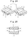
- the engaging projection 62 may be provided on the front and rear end of the half part 51, as shown in a seventh alteration illustrated in FIGS. 24 and 25.
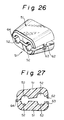
- an eighth alteration shown in FIGS. 26 and 27 includes a selfhinge 64 which interconnects the half parts 51, 51 and the engaging pawls 62 and engaging recesses 63.
- This mechanism makes it possible to handle both half parts 51, 51 as a single part before clamping the core wires between the half parts 51, 51, thereby simplifying parts management during a production process.
- a ninth alteration shown in FIGS. 28 and 29 has only the selfhinge. This alteration, however, can also simplify parts management.
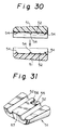
- FIG. 30 shows a tenth alteration.
- a difference between the tenth alteration and the second embodiment is to provide a structure of grooves in each half part 51 of the plug body. The other elements between them are the same.
- Each half part 51 is provided with two grooves 52.
- Each groove 52 has three ridges 54 which extend circumferentially and are spaced axially. The heights of the ridges 54 are different and are increased toward the terminal insertion opening 131.
- the recesses 55 and engaging holes 51 may be provided in and on the fitting face of the half part 51, as shown in an eleventh alteration illustrated in FIG. 31.
- a twelfth alteration shown in FIG. 32 is provided with the engaging hole 56 in the rear end face of the half part 51.
- a thirteenth alteration shown in FIG. 33 is provided on the top face of the rear end of the half part 51 with an engaging projection 65 adapted to be hooked by a tool (not shown) to pull out the half part 51 from the connector housing 10.
- FIG. 34 shows a fourteenth alteration in which the mold resin 100 is firmly attached to the connector housing 10.
- the connector housing 10 is provided on its rear end with a single annular rib 15 which is provided with a plurality of through holes 152 into which the mold resin enters. This assures that the mold resin layer is prevented from coming out of the connector housing 10.
- Two annular ribs each having a plurality of through holes may be provided on the rear end of the connector housing 10 although they are not shown in the drawing.
- the annular ribs 15 and 16 may not be provided in the connector housing 10.
- the connector housing 10 may be provided in its rear end with a plurality of through holes 101 into which the mold resin enters, thereby preventing the mold resin layer 100 from coming out of the connector housing 10. If a small force is required to prevent the layer 100 from coming-out, a sixteenth alteration as shown in FIG. 36 may be provided with no annular ribs 15, 16 and through holes 101.
- FIG. 37 shows a seventeenth alteration.
- a difference between the seventeenth alteration and the second embodiment is to omit the waterproofing seal 30.
- the other elements between them are the same and are indicated by the same signs to avoid a repetition of explanation.
- FIG. 38 shows an eighteenth alteration having a plug body different from that of the second embodiment.
- the plug body includes two tapered cylindrical member 71, 71 which are divided into an upper half part and a lower half part. The taper of each member 71 is conformed to each cavity in the connector housing.
- a nineteenth alteration shown in FIG. 39 includes a tapered flat cylindrical member 72 and a partition member 73 to be inserted into the member 72 to define two through holes respectively for permitting the core wires to pass through.
- a twentieth alteration shown in FIG. 40 includes a single tapered plug body 74 with two wire through holes 75.
- FIG. 41 shows a twenty-first alteration which improves the connector housing and plug body in the second embodiment.
- the connector housing 10 has a stepped chamber 14.
- the plug body 76 has a stepped portion 76a which conforms to the stepped chamber 14. This structure can prevent the plug body 76 from entering too far into the chamber toward the cavities 12 upon insertion of the plug body 76 or injection of the mold resin.
- FIGS. 42 and 43 show a twenty-second alteration having a different improvement.
- a plug body 77 is provided on its exterior with guide ribs 78 extending in the inserting direction.
- the connector housing 10 is provided in its interior with two guide grooves 79 each of which receives each guide rib 78. This structure has advantages that the plug body 77 can be guided into the chamber 14 without causing any plays and can make firm contact with the chamber 14.
- the plug body to which adhesive, expansive agent, seal agent or rubber layer is applied may be disposed in the plug body accommodating chamber.
- FIGS. 44 to 72 a third embodiment of a waterproofed connector in accordance with the present invention will be described below by referring to FIGS. 44 to 72. Since the same signs in the second embodiment shown in FIGS. 44 to 72 as those in the first and second embodiments shown in FIGS. 1 to 9 and 10 to 43 indicate the same elements or parts, respectively, explanations of such structure and arrangement will be omitted below.
- a plug body 50 made of a hard plastic material is disposed through the terminal insertion opening 131 in the plug body accommodating chamber 14 in the connector housing 10. As shown in FIG. 44, the plug body 50 is divided into a pair of upper and lower half parts 51 and 51 to clamp two core wires 22 between the parts 51. Each half part 51 is provided with two U-shaped grooves on the fitting face to be coupled to the mating half part. When the half parts 51, 51 are coupled to each other, the opposed grooves 52 define wire through holes 53 which permit the wires 22 to pass therethrough. In the third embodiment, the plug body 50 and the chamber 14 are not tapered.
- each half part 51 is provided in its upper end face with a recess 55 in which a receiving hole 56 is formed.
- a tool (not shown) can hook in the hole 56 to pull the part 51 out of the chamber 14.
- the terminal metal fixture 40 is crimped on an end of each core wire 22 of the electrical cable 20 with the waterproofing seal 30 being attached to a section near the end.
- the terminal metal fixture 40 is inserted into each cavity 12 in the connector housing 10 and then the retainer 19 is pushed onto a locking position to prevent the terminal metal fixture 40 from coming out of the cavity 12.
- one of the half parts 51, 51 is inserted into the plug body accommodating chamber 14 through the terminal insertion opening 131 in the connector housing 10 while the half part 51 is in contact with the underside of the core wires 22.
- the other half part 51 is inserted into the chamber 14 through the opening 131 while the part 51 is in contact with the upside of the core wires 22.
- Two half parts 51, 51 clamp the core wires 22, 22, so that the core wires 22, 22 pass through the holes 53, 53 in the plug body 50, respectively.
- the ridges 54 on the grooves 52 in each half part 51 bite the insulation cover 221 of the core wires 22. Consequently, the plug body 50 is compressed in the chamber 14 in the connector housing 10 while the plug body 50 firmly clamps the core wires 22.
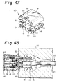
- the connector housing 10 under the present state is set in the mold 110 as shown in FIG. 48, the mold resin is injected in the mold 110, and the molded product is removed from the mold 110 by opening the mold 110 after cooling.
- the waterproofed connector having the mold resin layer 100 on the rear end of the connector housing 10 is obtained.
- the mold resin layer 100 enclosing the cable inlet for the electrical cable 20 in the connector housing 10 can effectively prevent the water from entering through the cable inlet into the connector housing 10.
- Minute gaps may be generated between the mold resin layer 100 and the connector housing 10 or the core wires 22 after molding. Since the present embodiment provides the mold resin layer 100 around the rear end of the connector housing 10 and the waterproofing seal 30 in the terminal insertion opening 131 of the cavities 12, the waterproofing seal 30 can prevent the water from entering the cavities 12 toward the terminal metal fixtures 40 even if water enters the opening 131 through the gaps between the mold resin layer 100 and the core wires 22 or the connector housing 10.
- This embodiment can reconcile a low cost and a high level of waterproofing.
- the resilient mold resin layer 100 formed on the cable inlet for the electrical cable 20 can follow any bend in the cable 20 to maintain the waterproofing function.
- the resilient mold resin layer 100 is not broken by any hit of stones or the like when a moving vehicle spatters the stones or the like, thereby enhancing a reliability of the connector.
- the mold resin layer 100 can prevent the mold resin from flowing forcibly into the cavities 12 toward the waterproofing seal 30 upon molding.
- the mold resin pushes the plug body 50 toward the waterproofing seal 30, thereby preventing the mold resin from leaking into the cavities toward the terminal metal fixture 40. It is also possible to raise the injection pressure of the mold resin. Even if the electrical cable 20 or the core wires 22 are subjected to any bending force, the plug body 50 maintains the core wires 22 at the center in the terminal insertion opening 131 so that the bending force is not transmitted to the waterproofing seal 30, thereby enhancing the waterproofing function of the seal 30.
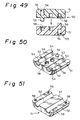
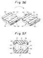
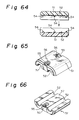
- Each alteration (FIGS. 49 to 72) in the third embodiment substantially corresponds to each alteration (FIGS. 15 to 36) in the second embodiment.
- the plug body 50 in the alterations in the second embodiment is tapered while the plug body 50 in the alterations in the third embodiment is not tapered.
- the plug body 50 in the third embodiment has no directivity since the plug body 50 is not tapered.
- FIG. 65 shows an alteration in which the plug body arranged in the chamber 14 is readily removed.
- the half part 51 is provided in its top faces of the front and rear ends with recesses 55 in which engaging holes 56 are formed to be hooked by a tool (not shown) when the half part 51 must be pulled out of the chamber 14.
- the holes 56 in the recesses 55 in the opposite ends of the half part 51 can be disposed in the chamber 14 in the connector housing 10 without taking care of the directivity of the plug body 50.
- the recesses 55 and engaging holes 56 may be provided in the inner face of the front and rear ends of the half part 51.
Landscapes
- Connector Housings Or Holding Contact Members (AREA)
Applications Claiming Priority (9)
| Application Number | Priority Date | Filing Date | Title |
|---|---|---|---|
| JP6209234A JP2785700B2 (ja) | 1994-08-09 | 1994-08-09 | 防水コネクタ |
| JP209234/94 | 1994-08-09 | ||
| JP20923494 | 1994-08-09 | ||
| JP6217974A JP2785704B2 (ja) | 1994-08-18 | 1994-08-18 | 防水コネクタ |
| JP6217973A JP2785703B2 (ja) | 1994-08-18 | 1994-08-18 | 防水コネクタ |
| JP217974/94 | 1994-08-18 | ||
| JP21797394 | 1994-08-18 | ||
| JP21797494 | 1994-08-18 | ||
| JP217973/94 | 1994-08-18 |
Publications (3)
| Publication Number | Publication Date |
|---|---|
| EP0696827A2 true EP0696827A2 (fr) | 1996-02-14 |
| EP0696827A3 EP0696827A3 (fr) | 1997-01-08 |
| EP0696827B1 EP0696827B1 (fr) | 2000-12-13 |
Family
ID=27328975
Family Applications (1)
| Application Number | Title | Priority Date | Filing Date |
|---|---|---|---|
| EP95305407A Expired - Lifetime EP0696827B1 (fr) | 1994-08-09 | 1995-08-02 | Connecteur étanché |
Country Status (3)
| Country | Link |
|---|---|
| US (1) | US5580264A (fr) |
| EP (1) | EP0696827B1 (fr) |
| DE (1) | DE69519608T2 (fr) |
Cited By (11)
| Publication number | Priority date | Publication date | Assignee | Title |
|---|---|---|---|---|
| WO1997036346A1 (fr) * | 1996-03-27 | 1997-10-02 | The Whitaker Corporation | Connecteur electrique etanche |
| EP1079470A1 (fr) * | 1999-08-23 | 2001-02-28 | Harness System Technologies Research, Ltd. | Connecteur étanche |
| FR2900507A1 (fr) * | 2006-04-28 | 2007-11-02 | Connecteurs Electr Deutsch Soc | Bouchon d'etancheite longitudinale d'un connecteur |
| WO2011042005A3 (fr) * | 2009-10-09 | 2011-07-21 | Harting Electric Gmbh & Co. Kg | Traversée de câble dans des boîtiers de connecteurs |
| WO2011110599A1 (fr) * | 2010-03-09 | 2011-09-15 | Bontaz Centre | Dispositif de connexion electrique etanche a travers une paroi et procede de realisation correspondant |
| CN101364686B (zh) * | 2007-08-09 | 2011-10-05 | 矢崎总业株式会社 | 用于防水连接器的橡胶塞和防水连接器 |
| WO2012136446A1 (fr) * | 2011-04-07 | 2012-10-11 | Robert Bosch Gmbh | Étanchéisation de boîtiers pour éléments de contacts enfichables |
| WO2014040699A1 (fr) * | 2012-09-15 | 2014-03-20 | Leoni Bordnetz-Systeme Gmbh | Connecteur électrique ainsi que boîtier de connecteur |
| EP2720323A1 (fr) * | 2012-10-15 | 2014-04-16 | The Boeing Company | Connecteur électrique amélioré de réduction de court-circuit électrique provoqué par un liquide |
| WO2018206601A1 (fr) * | 2017-05-08 | 2018-11-15 | Leoni Bordnetz-Systeme Gmbh | Procédé de montage d'un connecteur mâle sur un câble à gaine multiconducteur et connecteur électrique |
| WO2023104421A1 (fr) * | 2021-12-10 | 2023-06-15 | Enova Solutions Ag | Connecteur enfichable |
Families Citing this family (81)
| Publication number | Priority date | Publication date | Assignee | Title |
|---|---|---|---|---|
| JP3288217B2 (ja) * | 1996-03-06 | 2002-06-04 | 矢崎総業株式会社 | リヤホルダ及びこのリヤホルダを用いた防水コネクタ |
| US5865636A (en) * | 1996-03-27 | 1999-02-02 | The Whitaker Corporation | Seal for use with an electrical connector comprising insulation displacement type contacts |
| US5984714A (en) * | 1997-10-30 | 1999-11-16 | A-G Geophysical Products, Inc. | Electrical connector tail |
| JP3517109B2 (ja) * | 1998-03-31 | 2004-04-05 | 矢崎総業株式会社 | 防水コネクタ及び防水コネクタの組立方法 |
| JP3547988B2 (ja) | 1998-03-31 | 2004-07-28 | 矢崎総業株式会社 | 防水コネクタ及び防水処理方法 |
| JP3566541B2 (ja) | 1998-03-31 | 2004-09-15 | 矢崎総業株式会社 | 防水コネクタ及び防水処理方法 |
| JP3566540B2 (ja) | 1998-03-31 | 2004-09-15 | 矢崎総業株式会社 | 防水コネクタ |
| JPH11354201A (ja) | 1998-06-10 | 1999-12-24 | Yazaki Corp | 防水コネクタ |
| JP3500065B2 (ja) | 1998-06-25 | 2004-02-23 | 矢崎総業株式会社 | 防水コネクタ |
| JP3540164B2 (ja) | 1998-07-06 | 2004-07-07 | 矢崎総業株式会社 | 防水コネクタ |
| JP2000323226A (ja) * | 1999-03-09 | 2000-11-24 | Sumitomo Wiring Syst Ltd | コネクタ |
| JP3535034B2 (ja) * | 1999-03-29 | 2004-06-07 | 矢崎総業株式会社 | 防水コネクタ |
| JP2001118626A (ja) * | 1999-10-18 | 2001-04-27 | Yazaki Corp | コネクタハウジングとその製造方法 |
| US6497589B1 (en) * | 2000-11-17 | 2002-12-24 | General Electric Company | Methods and apparatus for electrical connections |
| US6364675B1 (en) * | 2000-12-06 | 2002-04-02 | Bonnie Brauer | Electrical connector with tension disconnect |
| WO2004032587A1 (fr) * | 2002-10-03 | 2004-04-15 | Poly-Products Ind. Co. Ltd. | Dispositif electrique a boitier etanche et procede de fabrication correspondant |
| TW549710U (en) * | 2002-11-15 | 2003-08-21 | Hon Hai Prec Ind Co Ltd | Cable end connector assembly |
| TW557006U (en) * | 2002-11-15 | 2003-10-01 | Hon Hai Prec Ind Co Ltd | Cable connector assembly |
| TW572419U (en) * | 2003-03-18 | 2004-01-11 | Delta Electronics Inc | Power line securing module for electronic apparatus |
| JP2004355987A (ja) * | 2003-05-30 | 2004-12-16 | Nec Corp | 防水型モジュラコネクタ |
| JP2005005177A (ja) * | 2003-06-13 | 2005-01-06 | Yazaki Corp | ケーブルとハウジング間の防水装置 |
| US7104840B2 (en) * | 2003-06-27 | 2006-09-12 | Yazaki Corporation | Electrical connector |
| DE102004061663B3 (de) * | 2004-12-22 | 2006-06-14 | Gessmann Gmbh & Co. Kg | Elektrisches Kupplungselement |
| US7260891B2 (en) * | 2005-01-13 | 2007-08-28 | Siemens Vdo Automotive Corporation | Connector overmold spacer |
| DE102005009442A1 (de) * | 2005-03-02 | 2006-09-14 | Hirschmann Automotive Gmbh | Steckverbinder mit einer Crimp-Abdichtung und/oder einer Kabelhalterung |
| DE102005009441A1 (de) * | 2005-03-02 | 2006-09-14 | Hirschmann Automotive Gmbh | Steckverbinder mit einer Crimp-Abdichtung und/oder einer Kabelhalterung |
| JP2009252712A (ja) * | 2008-04-11 | 2009-10-29 | Yazaki Corp | 防水コネクタ及び防水コネクタの製造方法 |
| DE102008018758A1 (de) * | 2008-04-14 | 2009-10-15 | Kmi-Holding Gmbh | Steckverbindervorrichtung |
| CN101577391B (zh) * | 2008-05-07 | 2011-03-23 | 富士康(昆山)电脑接插件有限公司 | 插头连接器及其制造方法 |
| US8734174B2 (en) * | 2009-02-20 | 2014-05-27 | Yazaki Corporation | Waterproof connector having an integrally formed elastic seal member |
| US20100238621A1 (en) * | 2009-03-20 | 2010-09-23 | Tracy Mark S | Insert-molded conductor |
| CN102365791B (zh) * | 2009-03-24 | 2014-12-10 | 矢崎总业株式会社 | 防水连接器 |
| CN201438573U (zh) * | 2009-05-14 | 2010-04-14 | 富士康(昆山)电脑接插件有限公司 | 电连接器组件 |
| CN102742090B (zh) * | 2009-11-30 | 2016-01-13 | 富加宜汽车控股公司 | 密封件、包括该密封件的系统和连接器组件、组装和制造方法 |
| CN103210548B (zh) * | 2010-11-12 | 2016-02-10 | 赫斯曼汽车有限公司 | 插接连接器以及用于制造这种插接连接器的方法 |
| JP5890985B2 (ja) * | 2011-08-30 | 2016-03-22 | 矢崎総業株式会社 | コネクタ及びこのコネクタに用いられる被覆部材 |
| JP2014530452A (ja) * | 2011-09-20 | 2014-11-17 | マルチ−ホールディング アーゲー | プラグコネクタ |
| CN104685729B (zh) | 2012-07-16 | 2017-08-08 | 美国北卡罗来纳康普公司 | 平衡的插头连接器和插座连接器 |
| DE202013000969U1 (de) * | 2013-01-31 | 2014-05-08 | Rosenberger Hochfrequenztechnik Gmbh & Co. Kg | Steckverbinder |
| US9930592B2 (en) | 2013-02-19 | 2018-03-27 | Mimosa Networks, Inc. | Systems and methods for directing mobile device connectivity |
| US9179336B2 (en) | 2013-02-19 | 2015-11-03 | Mimosa Networks, Inc. | WiFi management interface for microwave radio and reset to factory defaults |
| WO2014137370A1 (fr) * | 2013-03-06 | 2014-09-12 | Mimosa Networks, Inc. | Appareil étanche à l'eau pour câbles et interfaces de câbles |
| US9362629B2 (en) | 2013-03-06 | 2016-06-07 | Mimosa Networks, Inc. | Enclosure for radio, parabolic dish antenna, and side lobe shields |
| US10742275B2 (en) | 2013-03-07 | 2020-08-11 | Mimosa Networks, Inc. | Quad-sector antenna using circular polarization |
| US9191081B2 (en) | 2013-03-08 | 2015-11-17 | Mimosa Networks, Inc. | System and method for dual-band backhaul radio |
| US9735495B2 (en) * | 2013-03-25 | 2017-08-15 | Fci Americas Technology Llc | Electrical cable assembly |
| US9295103B2 (en) | 2013-05-30 | 2016-03-22 | Mimosa Networks, Inc. | Wireless access points providing hybrid 802.11 and scheduled priority access communications |
| US10938110B2 (en) | 2013-06-28 | 2021-03-02 | Mimosa Networks, Inc. | Ellipticity reduction in circularly polarized array antennas |
| US9001689B1 (en) | 2014-01-24 | 2015-04-07 | Mimosa Networks, Inc. | Channel optimization in half duplex communications systems |
| US9780892B2 (en) | 2014-03-05 | 2017-10-03 | Mimosa Networks, Inc. | System and method for aligning a radio using an automated audio guide |
| US9998246B2 (en) | 2014-03-13 | 2018-06-12 | Mimosa Networks, Inc. | Simultaneous transmission on shared channel |
| US10958332B2 (en) | 2014-09-08 | 2021-03-23 | Mimosa Networks, Inc. | Wi-Fi hotspot repeater |
| USD752566S1 (en) | 2014-09-12 | 2016-03-29 | Mimosa Networks, Inc. | Wireless repeater |
| JP6536378B2 (ja) * | 2015-11-24 | 2019-07-03 | 日立金属株式会社 | コネクタ及びその製造方法ならびにワイヤハーネス |
| US10749263B2 (en) | 2016-01-11 | 2020-08-18 | Mimosa Networks, Inc. | Printed circuit board mounted antenna and waveguide interface |
| GB2547958B (en) | 2016-03-04 | 2019-12-18 | Commscope Technologies Llc | Two-wire plug and receptacle |
| TWI746561B (zh) | 2016-05-31 | 2021-11-21 | 美商安芬諾股份有限公司 | 高效能纜線終端 |
| EP3491697B8 (fr) | 2016-07-29 | 2023-10-18 | Mimosa Networks, Inc. | Réseau d'antennes à point d'accès multibandes |
| US10090614B2 (en) * | 2016-10-18 | 2018-10-02 | Delphi Technologies, Inc. | Electrical connector having sealed snap-in locking cavity plugs |
| US20180241139A1 (en) * | 2017-02-23 | 2018-08-23 | Lear Corporation | Electrical terminal assembly and method of assembling the same |
| AU2018258285B2 (en) * | 2017-04-24 | 2023-05-04 | Commscope Technologies Llc | Connectors for a single twisted pair of conductors |
| CN110945724B (zh) | 2017-06-08 | 2021-08-27 | 康普技术有限责任公司 | 用于单扭绞导体对的连接器 |
| US11070006B2 (en) | 2017-08-03 | 2021-07-20 | Amphenol Corporation | Connector for low loss interconnection system |
| US10511074B2 (en) | 2018-01-05 | 2019-12-17 | Mimosa Networks, Inc. | Higher signal isolation solutions for printed circuit board mounted antenna and waveguide interface |
| WO2019147774A1 (fr) | 2018-01-26 | 2019-08-01 | Commscope Technologies Llc | Connecteurs pour paire torsadée unique de conducteurs |
| EP3759765A4 (fr) | 2018-02-26 | 2022-04-13 | CommScope Technologies LLC | Connecteurs et contacts de paire torsadée unique de conducteurs |
| US11069986B2 (en) | 2018-03-02 | 2021-07-20 | Airspan Ip Holdco Llc | Omni-directional orthogonally-polarized antenna system for MIMO applications |
| JP6897621B2 (ja) | 2018-03-30 | 2021-06-30 | 株式会社オートネットワーク技術研究所 | ワイヤハーネス |
| JP6897620B2 (ja) | 2018-03-30 | 2021-06-30 | 株式会社オートネットワーク技術研究所 | ワイヤハーネス |
| DE102018111919A1 (de) | 2018-05-17 | 2019-11-21 | Unger Kabel-Konfektionstechnik GmbH | Gerätedose zum elektrischen Verbinden eines Elektrogeräts sowie Verbindungskabel und Elektrogerät |
| TWI740050B (zh) * | 2018-06-01 | 2021-09-21 | 日商島野股份有限公司 | 用於人力交通工具之電纜線總成 |
| JP2019220251A (ja) * | 2018-06-15 | 2019-12-26 | 住友電装株式会社 | 多芯電線の防水構造 |
| US11289821B2 (en) | 2018-09-11 | 2022-03-29 | Air Span Ip Holdco Llc | Sector antenna systems and methods for providing high gain and high side-lobe rejection |
| WO2020172395A1 (fr) | 2019-02-22 | 2020-08-27 | Amphenol Corporation | Ensemble connecteur de câble haute performance |
| EP3939129A4 (fr) | 2019-03-15 | 2022-12-14 | CommScope Technologies LLC | Connecteurs et contacts pour une paire torsadée unique de conducteurs |
| JP7259455B2 (ja) * | 2019-03-22 | 2023-04-18 | 株式会社オートネットワーク技術研究所 | コネクタ付きケース、コネクタ付きワイヤーハーネス、及びエンジンコントロールユニット |
| KR102060478B1 (ko) * | 2019-03-25 | 2019-12-30 | 엘지전자 주식회사 | 터미널 구조체 및 이를 포함하는 전동식 압축기 |
| CN110299643A (zh) * | 2019-07-02 | 2019-10-01 | 罗森伯格(上海)通信技术有限公司 | 一种室外防水接头盒 |
| DE102021104539A1 (de) | 2021-02-25 | 2022-08-25 | Robert Bosch Gesellschaft mit beschränkter Haftung | Steckervorrichtung für ein Kabel |
| CN117203862A (zh) * | 2021-06-11 | 2023-12-08 | 赫斯曼汽车有限公司 | 具有内部密封件的插接连接装置 |
| CN115460025A (zh) * | 2022-08-23 | 2022-12-09 | 智道网联科技(北京)有限公司 | 单对以太网供电通信电路及模块 |
Citations (1)
| Publication number | Priority date | Publication date | Assignee | Title |
|---|---|---|---|---|
| JPH0573871U (ja) | 1992-03-06 | 1993-10-08 | 住友電装株式会社 | 差し込みモールドプラグ |
Family Cites Families (9)
| Publication number | Priority date | Publication date | Assignee | Title |
|---|---|---|---|---|
| SE415511B (sv) * | 1979-01-08 | 1980-10-06 | Volvo Ab | Elektriskt anslutningsdon |
| DE8706150U1 (fr) * | 1986-05-15 | 1987-07-23 | Werner Turck Gmbh & Co Kg, 5884 Halver, De | |
| US5114359A (en) * | 1990-07-13 | 1992-05-19 | Sumitomo Wiring Systems Ltd. | Connector |
| JP2659295B2 (ja) * | 1991-09-12 | 1997-09-30 | 矢崎総業株式会社 | 防水コネクタ用ゴム栓の自動供給方法及び防水コネクタ用ゴム栓 |
| JP2598584Y2 (ja) * | 1991-09-12 | 1999-08-16 | 矢崎総業株式会社 | 組立式シールドコネクタ |
| GB9212732D0 (en) * | 1992-06-16 | 1992-07-29 | Amp Gmbh | Sealed electrical connector and method of making the same |
| JP2575393Y2 (ja) * | 1992-11-11 | 1998-06-25 | 住友電装株式会社 | 防水コネクタ |
| JPH0749741Y2 (ja) * | 1993-06-04 | 1995-11-13 | 小林電機工業株式会社 | 防水コネクタ |
| JP2568643Y2 (ja) * | 1993-11-24 | 1998-04-15 | 住友電装株式会社 | 防水構造及びコネクタ |
-
1995
- 1995-07-27 US US08/507,927 patent/US5580264A/en not_active Expired - Lifetime
- 1995-08-02 EP EP95305407A patent/EP0696827B1/fr not_active Expired - Lifetime
- 1995-08-02 DE DE69519608T patent/DE69519608T2/de not_active Expired - Fee Related
Patent Citations (1)
| Publication number | Priority date | Publication date | Assignee | Title |
|---|---|---|---|---|
| JPH0573871U (ja) | 1992-03-06 | 1993-10-08 | 住友電装株式会社 | 差し込みモールドプラグ |
Cited By (24)
| Publication number | Priority date | Publication date | Assignee | Title |
|---|---|---|---|---|
| WO1997036346A1 (fr) * | 1996-03-27 | 1997-10-02 | The Whitaker Corporation | Connecteur electrique etanche |
| EP1079470A1 (fr) * | 1999-08-23 | 2001-02-28 | Harness System Technologies Research, Ltd. | Connecteur étanche |
| US6331124B1 (en) | 1999-08-23 | 2001-12-18 | Autonetworks Technologies Ltd. | Waterproof connector |
| FR2900507A1 (fr) * | 2006-04-28 | 2007-11-02 | Connecteurs Electr Deutsch Soc | Bouchon d'etancheite longitudinale d'un connecteur |
| CN101364686B (zh) * | 2007-08-09 | 2011-10-05 | 矢崎总业株式会社 | 用于防水连接器的橡胶塞和防水连接器 |
| WO2011042005A3 (fr) * | 2009-10-09 | 2011-07-21 | Harting Electric Gmbh & Co. Kg | Traversée de câble dans des boîtiers de connecteurs |
| FR2957463A1 (fr) * | 2010-03-09 | 2011-09-16 | Bontaz Centre Sa | Dispositif de connexion electrique etanche a travers une paroi |
| CN102884684A (zh) * | 2010-03-09 | 2013-01-16 | 邦达中心 | 产生透壁密封电气连接的装置和其相应的制造方法 |
| CN102884684B (zh) * | 2010-03-09 | 2017-09-22 | 邦达研发中心 | 产生透壁密封电气连接的装置和其相应的制造方法 |
| WO2011110599A1 (fr) * | 2010-03-09 | 2011-09-15 | Bontaz Centre | Dispositif de connexion electrique etanche a travers une paroi et procede de realisation correspondant |
| US8905784B2 (en) | 2010-03-09 | 2014-12-09 | Bontaz Centre R & D | Device for producing a sealed electrical connection through a wall |
| CN103444009B (zh) * | 2011-04-07 | 2016-08-24 | 罗伯特·博世有限公司 | 用于插接接触元件的壳体的密封部 |
| WO2012136446A1 (fr) * | 2011-04-07 | 2012-10-11 | Robert Bosch Gmbh | Étanchéisation de boîtiers pour éléments de contacts enfichables |
| CN103444009A (zh) * | 2011-04-07 | 2013-12-11 | 罗伯特·博世有限公司 | 用于插接接触元件的壳体的密封部 |
| CN104813544B (zh) * | 2012-09-15 | 2017-04-12 | 莱尼电气系统有限公司 | 电接触插接器以及插接器壳体 |
| CN104813544A (zh) * | 2012-09-15 | 2015-07-29 | 莱尼电气系统有限公司 | 电接触插接器以及插接器壳体 |
| US9515404B2 (en) | 2012-09-15 | 2016-12-06 | Leoni Bordnetz-Systeme Gmbh | Electrical contact plug and plug housing |
| WO2014040699A1 (fr) * | 2012-09-15 | 2014-03-20 | Leoni Bordnetz-Systeme Gmbh | Connecteur électrique ainsi que boîtier de connecteur |
| US8998630B2 (en) | 2012-10-15 | 2015-04-07 | The Boeing Company | Non-conductive material with peaks and valleys surrounding a plurality of electrical contacts |
| EP2720323A1 (fr) * | 2012-10-15 | 2014-04-16 | The Boeing Company | Connecteur électrique amélioré de réduction de court-circuit électrique provoqué par un liquide |
| WO2018206601A1 (fr) * | 2017-05-08 | 2018-11-15 | Leoni Bordnetz-Systeme Gmbh | Procédé de montage d'un connecteur mâle sur un câble à gaine multiconducteur et connecteur électrique |
| CN110603692A (zh) * | 2017-05-08 | 2019-12-20 | 莱尼电气系统有限公司 | 用于将插塞器装配在多芯的护套导线上的方法以及电的插塞器 |
| US11309656B2 (en) | 2017-05-08 | 2022-04-19 | Leoni Bordnetz-Systeme Gmbh | Method for assembling a plug on a multi-core sheathed cable, and electrical plug |
| WO2023104421A1 (fr) * | 2021-12-10 | 2023-06-15 | Enova Solutions Ag | Connecteur enfichable |
Also Published As
| Publication number | Publication date |
|---|---|
| US5580264A (en) | 1996-12-03 |
| DE69519608D1 (de) | 2001-01-18 |
| DE69519608T2 (de) | 2001-05-10 |
| EP0696827B1 (fr) | 2000-12-13 |
| EP0696827A3 (fr) | 1997-01-08 |
Similar Documents
| Publication | Publication Date | Title |
|---|---|---|
| EP0696827B1 (fr) | Connecteur étanché | |
| US5718596A (en) | Connector engaging structure | |
| EP1583184B1 (fr) | Joint d'étanchéité pour connecteur étanche et son procédé de moulage | |
| US8177584B2 (en) | Connector with wire sealing resilient plug | |
| US6464522B2 (en) | Connector with terminal protective plate having internal and external sealing members | |
| JP3485150B2 (ja) | シールドコネクタ | |
| US5278357A (en) | Electric wire holding case preventing of oil leak | |
| EP0574862B1 (fr) | Connecteur électrique cacheté et méthode de sa fabrication | |
| CN102362072B (zh) | 压缩机插头组件 | |
| US7262363B2 (en) | Electric wire protective cap | |
| US5622512A (en) | Apparatus for forming waterproof connection | |
| US6817888B2 (en) | Connector with cover | |
| JP5477653B2 (ja) | 機器用コネクタ | |
| JP2001015205A (ja) | 防水コネクタ | |
| JP3285004B2 (ja) | コネクタ | |
| JP2003109702A (ja) | 端子防油水構造 | |
| WO2013183305A1 (fr) | Connecteur | |
| JP3947093B2 (ja) | 機器用コネクタ | |
| JP2785704B2 (ja) | 防水コネクタ | |
| JP2586314Y2 (ja) | 防水コネクタ | |
| US7086899B1 (en) | Waterproof connector | |
| JP2785703B2 (ja) | 防水コネクタ | |
| JP6438675B2 (ja) | コネクタの防水構造 | |
| JP3119119B2 (ja) | 圧接ジョイントコネクタ | |
| JP2011060426A (ja) | コネクタ |
Legal Events
| Date | Code | Title | Description |
|---|---|---|---|
| PUAI | Public reference made under article 153(3) epc to a published international application that has entered the european phase |
Free format text: ORIGINAL CODE: 0009012 |
|
| 17P | Request for examination filed |
Effective date: 19950824 |
|
| AK | Designated contracting states |
Kind code of ref document: A2 Designated state(s): DE FR GB |
|
| PUAL | Search report despatched |
Free format text: ORIGINAL CODE: 0009013 |
|
| AK | Designated contracting states |
Kind code of ref document: A3 Designated state(s): DE FR GB |
|
| 17Q | First examination report despatched |
Effective date: 19990122 |
|
| GRAG | Despatch of communication of intention to grant |
Free format text: ORIGINAL CODE: EPIDOS AGRA |
|
| 17Q | First examination report despatched |
Effective date: 19990122 |
|
| GRAG | Despatch of communication of intention to grant |
Free format text: ORIGINAL CODE: EPIDOS AGRA |
|
| GRAH | Despatch of communication of intention to grant a patent |
Free format text: ORIGINAL CODE: EPIDOS IGRA |
|
| GRAH | Despatch of communication of intention to grant a patent |
Free format text: ORIGINAL CODE: EPIDOS IGRA |
|
| GRAA | (expected) grant |
Free format text: ORIGINAL CODE: 0009210 |
|
| AK | Designated contracting states |
Kind code of ref document: B1 Designated state(s): DE FR GB |
|
| REF | Corresponds to: |
Ref document number: 69519608 Country of ref document: DE Date of ref document: 20010118 |
|
| ET | Fr: translation filed | ||
| PG25 | Lapsed in a contracting state [announced via postgrant information from national office to epo] |
Ref country code: GB Free format text: LAPSE BECAUSE OF NON-PAYMENT OF DUE FEES Effective date: 20010802 |
|
| PLBE | No opposition filed within time limit |
Free format text: ORIGINAL CODE: 0009261 |
|
| STAA | Information on the status of an ep patent application or granted ep patent |
Free format text: STATUS: NO OPPOSITION FILED WITHIN TIME LIMIT |
|
| 26N | No opposition filed | ||
| GBPC | Gb: european patent ceased through non-payment of renewal fee |
Effective date: 20010802 |
|
| PG25 | Lapsed in a contracting state [announced via postgrant information from national office to epo] |
Ref country code: FR Free format text: LAPSE BECAUSE OF NON-PAYMENT OF DUE FEES Effective date: 20020430 |
|
| PG25 | Lapsed in a contracting state [announced via postgrant information from national office to epo] |
Ref country code: DE Free format text: LAPSE BECAUSE OF NON-PAYMENT OF DUE FEES Effective date: 20020501 |
|
| REG | Reference to a national code |
Ref country code: FR Ref legal event code: ST |