EP0690940B1 - Schienenanordnung - Google Patents
Schienenanordnung Download PDFInfo
- Publication number
- EP0690940B1 EP0690940B1 EP94911926A EP94911926A EP0690940B1 EP 0690940 B1 EP0690940 B1 EP 0690940B1 EP 94911926 A EP94911926 A EP 94911926A EP 94911926 A EP94911926 A EP 94911926A EP 0690940 B1 EP0690940 B1 EP 0690940B1
- Authority
- EP
- European Patent Office
- Prior art keywords
- plate
- rail
- arrangement according
- foot
- projections
- Prior art date
- Legal status (The legal status is an assumption and is not a legal conclusion. Google has not performed a legal analysis and makes no representation as to the accuracy of the status listed.)
- Expired - Lifetime
Links
Images

Classifications
-
- E—FIXED CONSTRUCTIONS
- E01—CONSTRUCTION OF ROADS, RAILWAYS, OR BRIDGES
- E01B—PERMANENT WAY; PERMANENT-WAY TOOLS; MACHINES FOR MAKING RAILWAYS OF ALL KINDS
- E01B9/00—Fastening rails on sleepers, or the like
- E01B9/66—Rail fastenings allowing the adjustment of the position of the rails, so far as not included in the preceding groups
-
- E—FIXED CONSTRUCTIONS
- E01—CONSTRUCTION OF ROADS, RAILWAYS, OR BRIDGES
- E01B—PERMANENT WAY; PERMANENT-WAY TOOLS; MACHINES FOR MAKING RAILWAYS OF ALL KINDS
- E01B7/00—Switches; Crossings
- E01B7/22—Special sleepers for switches or crossings; Fastening means therefor
Definitions
- the invention relates to a rail arrangement
- a rail arrangement comprising a on a base plate arranged first rail such as stock rail with rail foot and one on a second plate like sliding chair arranged second rail like switch tongue with Rail foot that is fixed between projections like ribs and over fasteners like tension clamps is held down on the plate, with the second plate over at least one spring element is clamped to the base plate and the rail foot holds down the first rail or at least forms an anti-tip device for it.
- a device which consists of a separate from the Base plate arranged sliding chair, which with the foot of the stock rail one Form-fit forms and by a spring element lying on the side of the sliding chair is clamped on the base plate.
- the spring element has a U-shape and supports with his free leg ends on one above the base of the stock rail lying edition. If the U-shaped spring element breaks, the sliding chair can Stop holding the stock rail down.
- EP 0 336 311 B1 describes a device for fastening a rail, whose foot is held down by a spring element which is detachable from one on the Base plate arranged sliding chair goes out and is clamped over an abutment, is an integral part of the base plate.
- a two-part sliding chair is known from EP 0 113 515 A1.
- One with one The first part of a sliding chair that supports the section on the foot of the rail is detachable from a second part, which is firmly connected to a base plate.
- a stock rail fastening can be found in EP 0 343 149 A2, in which A spring with a progressive characteristic curve is supported on the stock rail base.
- One of the objects of the present invention is an apparatus of the type described above so that with a simple construction on the one hand a tilting of the rail is excluded and on the other hand it is ensured that the second plate even when the spring or springs holding it down breaks cannot be moved to the base plate uncontrollably, so that always a safe holding down of the rail is ensured like the stock rail. It is too Object of the invention, on the second plate in the second rail like switch tongue set desired positions or easily adapt to different To be able to make rail foot widths.
- the object is essentially achieved in that the second plate with the base plate is connected via an additional connecting element such as a screw element, with one of the fastenings for the rail foot of the second rail cooperates.
- the attachment to the rail foot of the second rail such as a the turnout tongue exciting screw element, in addition to that the second plate - in addition to the basically existing fuse via at least one spring element - is screwed onto the base plate to provide additional security Offer.
- the screw element penetrates at least one of the projections such as Rib.
- the screw element has a slot penetrates, which runs in the longitudinal direction of both the plate and the base plate.
- the slot has one for the slidably arranged Screw element suitable insertion opening, in particular from the rail remote End of the slot.
- the slot is at least partially in the second plate protrusions extending from the base plate as in the section L-shaped Cheeks or thighs is limited. These protrusions extend into Longitudinal direction of the base plate or plate, so that it is additionally secured against rotation.
- the projections such as ribs can optionally be slidable to the second plate be arranged, however, it is preferably provided that at least one of the Fastenings for the rail foot of the second rail are an integral part of the plate is.
- a further development of the invention is characterized in that the Protrusions such as ribs start from a third plate that is releasable with the second Plate over at least one of the cooperating with one of the fasteners Screw elements is connected.
- the third plate can be moved to the second plate can be arranged to the projections at the desired distance of the To be able to adjust the rail to each other.
- the projections are like ribs themselves preferably integral parts of the third plate.
- the projections like ribs itself in the longitudinal direction the third plate is slidable.
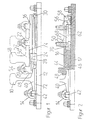
- a device for fastening a rail in the form of a stock rail (10) shown which is arranged on a base plate (12) via its rail foot (40) and on the one hand by a tension clamp (14) and on the other hand by a second plate (16) is held down.
- this has a structure of a Sliding chair for switch tongues with the restriction that that of the stock rail (10) associated rail (18) not displaceable, but between ribs (20) and (22) is arranged fixed to the stock rail (10).
- the base plate (16) is first detachable via rod spring elements (24) and (26) the base plate (12) also referred to as a ribbed plate.
- the Bar spring elements (24) and (26) between firmly emanating from the ribbed plate Abutments (28) and from the plate (16) outgoing supports braced.
- Support facing away from the rail bear the reference numerals (30) and (32).
- a rail side Support is denoted by (34).
- the abutment (28) forms an upper boundary of a channel (36) on the circumferential side is closed and open at the end.
- Each channel (36) points in the direction the tapered insertion opening (38), the openings (38) being such run that each spring element (26) from the side into the channel (36) and then stretched between the supports (32) and (34) and the abutments (28) becomes. This causes the plate (16) with its front above the Rail foot (40) extending section (48) on the rail foot to the Hold down.
- the second plate (16) has cavities, see above that the former are at least partially surrounded by the second plate (16).
- the rail-side supports (34) extend along the edge of the rail base (40) of the stock rail (10), on the opposite side as it were on one Rib (42) abuts and is held down by the tension clamp (14).
- the rod spring elements (24) and (26) also extend in from the longitudinal edge outgoing open channels, the underside of the ribbed plate (12) and the top are limited by the second plate (16). Each spring element (24) or (26) also projects from the rear of the respective channel to both the rod spring element (24, 26) easy to grasp for assembly and removal from the channel.
- An L-shaped projection (44) extends from the center of the ribbed plate (12) in the plate (16) and in the longitudinal direction of the recess (46) such intervenes that if the spring elements (24) and (26) fail, the plate (16) is lifted is excluded. This results in a further tilt protection for the rail (10).
- the projection (44) can also rest on the edge of the rail foot (40), so that additionally the function of a rib is exercised.
- the plate (16) is further secured by a screw (50), via which a clamp (52) extending from the rib (22) is tensioned, via which the foot (50 ') the second rail (18) is held down.
- a clamp (52) extending from the rib (22) is tensioned, via which the foot (50 ') the second rail (18) is held down.
- Corresponding tension clamp is provided, which is provided with the reference number (54). The screw that clamps the clamp is screwed to the plate (16).
- the screw (50) passes through a slot (56) which starts from the base plate (12) and ends at the top of the second plate (16).
- the slot faces away from the rail (56) accessible via an insertion opening (58) through which the screw (50) is inserted can be.
- the slot (56) is of legs or cheeks which are L-shaped in section limited the base plate (12), which are provided with the reference numerals (60) and (62) are and - as FIGS. 2 and 3 illustrate - in a chamber (64) Extend plate (16).
- the clear distance between the cross legs (66) and (68) of the Legs (60) and (62) are adapted to the diameter of the screw shaft, that is, less than its head or mother (70).
- the rib (22) is not an integral part of the base plate (16), this can are moved along the slot (56) together with the screw (50).
- the slot (56) may optionally have a length that allows both ribs delimiting a rail foot can be arranged displaceably.
- the teaching of the invention also has the advantage that only two Different types of plates are required to hold a switch tongue.
- the plates according to the invention can only last longer than usual a spring-held plates, as an additional fastening via the screw he follows. The jumps of inertia occurring in known switch areas are avoided.
Landscapes
- Engineering & Computer Science (AREA)
- Mechanical Engineering (AREA)
- Architecture (AREA)
- Civil Engineering (AREA)
- Structural Engineering (AREA)
- Seats For Vehicles (AREA)
- Insulated Conductors (AREA)
- Moving Of Heads (AREA)
- Chairs Characterized By Structure (AREA)
- Shutters For Cameras (AREA)
- Slot Machines And Peripheral Devices (AREA)
- Soil Working Implements (AREA)
- Near-Field Transmission Systems (AREA)
- Electric Propulsion And Braking For Vehicles (AREA)
- Mounting Components In General For Electric Apparatus (AREA)
- Noodles (AREA)
- Sorting Of Articles (AREA)
- Machines For Laying And Maintaining Railways (AREA)
- Scissors And Nippers (AREA)
- Train Traffic Observation, Control, And Security (AREA)
- Automotive Seat Belt Assembly (AREA)
- Connections Arranged To Contact A Plurality Of Conductors (AREA)
- Diaphragms For Electromechanical Transducers (AREA)
- Platform Screen Doors And Railroad Systems (AREA)
- Prostheses (AREA)
- Paper (AREA)
- Surgical Instruments (AREA)
- Forklifts And Lifting Vehicles (AREA)
Applications Claiming Priority (5)
| Application Number | Priority Date | Filing Date | Title |
|---|---|---|---|
| DE19934309515 DE4309515A1 (de) | 1993-03-25 | 1993-03-25 | Schienenanordnung |
| DE4309515 | 1993-03-25 | ||
| DE4310300 | 1993-03-30 | ||
| DE4310300 | 1993-03-30 | ||
| PCT/EP1994/000864 WO1994021859A1 (de) | 1993-03-25 | 1994-03-18 | Schienenanordnung |
Publications (2)
| Publication Number | Publication Date |
|---|---|
| EP0690940A1 EP0690940A1 (de) | 1996-01-10 |
| EP0690940B1 true EP0690940B1 (de) | 1998-06-03 |
Family
ID=25924275
Family Applications (1)
| Application Number | Title | Priority Date | Filing Date |
|---|---|---|---|
| EP94911926A Expired - Lifetime EP0690940B1 (de) | 1993-03-25 | 1994-03-18 | Schienenanordnung |
Country Status (12)
| Country | Link |
|---|---|
| EP (1) | EP0690940B1 (enExample) |
| KR (1) | KR100332005B1 (enExample) |
| AT (1) | ATE166937T1 (enExample) |
| AU (1) | AU6428194A (enExample) |
| DE (1) | DE59406141D1 (enExample) |
| DK (1) | DK0690940T3 (enExample) |
| ES (1) | ES2118397T3 (enExample) |
| FI (1) | FI954492A0 (enExample) |
| NO (1) | NO953753L (enExample) |
| PL (2) | PL310822A1 (enExample) |
| TW (1) | TW253921B (enExample) |
| WO (1) | WO1994021859A1 (enExample) |
Families Citing this family (3)
| Publication number | Priority date | Publication date | Assignee | Title |
|---|---|---|---|---|
| DE202009014434U1 (de) * | 2009-09-18 | 2010-02-11 | Vossloh-Werke Gmbh | Unterlegplatte für die Befestigung einer Schiene auf einem festen Untergrund und Befestigung einer Schiene |
| ES2397149B1 (es) * | 2011-01-12 | 2014-04-24 | Jez Sistemas Ferroviarios, S.L. | Placa para aparatos de vía de altas prestaciones |
| KR200453894Y1 (ko) | 2011-01-26 | 2011-06-01 | 주식회사베스트엔지니어링 | 레일 체결구조 |
Family Cites Families (5)
| Publication number | Priority date | Publication date | Assignee | Title |
|---|---|---|---|---|
| GB1489882A (en) * | 1974-10-26 | 1977-10-26 | Hixson R | Rail fastening assembly |
| US4326670A (en) * | 1980-06-23 | 1982-04-27 | Lord Corporation | Adjustable spring clip |
| DE3411122A1 (de) * | 1984-03-26 | 1985-10-03 | BWG Butzbacher Weichenbau GmbH, 6308 Butzbach | Vorrichtung zum befestigen von schienen |
| US4615484A (en) * | 1985-05-20 | 1986-10-07 | San Francisco Bay Area Rapid Transit District | Insulative protective device for rail fastener |
| AT389721B (de) * | 1988-05-20 | 1990-01-25 | Voest Alpine Maschinenbau | Vorrichtung zum befestigen von backenschienen in weichen |
-
1994
- 1994-03-18 EP EP94911926A patent/EP0690940B1/de not_active Expired - Lifetime
- 1994-03-18 PL PL94310822A patent/PL310822A1/xx unknown
- 1994-03-18 WO PCT/EP1994/000864 patent/WO1994021859A1/de not_active Ceased
- 1994-03-18 DE DE59406141T patent/DE59406141D1/de not_active Expired - Lifetime
- 1994-03-18 PL PL94109760U patent/PL57834Y1/xx unknown
- 1994-03-18 FI FI954492A patent/FI954492A0/fi unknown
- 1994-03-18 ES ES94911926T patent/ES2118397T3/es not_active Expired - Lifetime
- 1994-03-18 AT AT94911926T patent/ATE166937T1/de active
- 1994-03-18 AU AU64281/94A patent/AU6428194A/en not_active Abandoned
- 1994-03-18 KR KR1019950704174A patent/KR100332005B1/ko not_active Expired - Fee Related
- 1994-03-18 DK DK94911926T patent/DK0690940T3/da active
- 1994-04-11 TW TW083103183A patent/TW253921B/zh not_active IP Right Cessation
-
1995
- 1995-09-22 NO NO953753A patent/NO953753L/no unknown
Also Published As
| Publication number | Publication date |
|---|---|
| TW253921B (enExample) | 1995-08-11 |
| DK0690940T3 (da) | 1999-03-22 |
| FI954492A7 (fi) | 1995-09-22 |
| WO1994021859A1 (de) | 1994-09-29 |
| FI954492L (fi) | 1995-09-22 |
| ES2118397T3 (es) | 1998-09-16 |
| EP0690940A1 (de) | 1996-01-10 |
| PL310822A1 (en) | 1996-01-08 |
| DE59406141D1 (de) | 1998-07-09 |
| ATE166937T1 (de) | 1998-06-15 |
| FI954492A0 (fi) | 1995-09-22 |
| KR100332005B1 (ko) | 2002-08-13 |
| NO953753L (no) | 1995-11-03 |
| PL57834Y1 (en) | 2000-04-28 |
| AU6428194A (en) | 1994-10-11 |
| NO953753D0 (no) | 1995-09-22 |
Similar Documents
| Publication | Publication Date | Title |
|---|---|---|
| DE69008524T2 (de) | Halteranordnung. | |
| DE2554581A1 (de) | Anordnung eines abnehmbaren ballastgewichts | |
| DE29916465U1 (de) | Tisch-Einheit | |
| EP0455182A2 (de) | Vorrichtung zum Verriegeln einer Weichenzunge | |
| EP0659224B1 (de) | Vorrichtung zum befestigen einer schiene | |
| DE102004013347A1 (de) | Anordnung zum Umstellen einer Zungenschiene zu einer Backenschiene | |
| EP0690940B1 (de) | Schienenanordnung | |
| DE4309515A1 (de) | Schienenanordnung | |
| DE202007004182U1 (de) | Sicherheitsgeländer für ein Krankenbett | |
| DE3300863A1 (de) | Vorrichtung aus einer fuer schienen vorgesehenen schwelle und aus klipsen zur befestigung des fusses einer schiene an der schwelle | |
| DE19924579B4 (de) | Einrichtung zur lösbaren Befestigung eines Sitzes, insbesondere eines Fahrzeugsitzes | |
| DE102017100092B3 (de) | Behältertransportanlage mit einem auswechselbaren Bahnelement | |
| DE4421678B4 (de) | Befestigungs- und Haltevorrichtung für Gleisbauschutzabgrenzungen | |
| DE10157676A1 (de) | Einrichtung zum seitlichen Abstützen einer Schiene | |
| DE602005000447T2 (de) | Befestigungsvorrichtung einer Schiene für eine Eisenbahnweiche | |
| EP0778372B1 (de) | Gleitstuhl | |
| DE9417106U1 (de) | Bausatz zum Absperren von Gleisanlagen gegenüber Baustellen | |
| DE10338421A1 (de) | Vorrichtung zum Befestigen einer Schiene | |
| DE3417600A1 (de) | Verschluss zum halten eines in einen bremsbelagtraeger einschiebbaren bremsbelages fuer scheibenbremsen, insbesondere fuer schienenfahrzeuge | |
| DE3908824A1 (de) | Bausatz fuer einrichtungen zum lagern von gliedmassen | |
| DE1188110B (de) | Schienenbefestigung fuer Backenschienen in Weichen | |
| EP0745162B1 (de) | Schienenbefestigung | |
| DE4229900C2 (de) | Zugsperrvorrichtung für den Schulter- oder Beckengurt eines Fahrzeugsicherheitsgurtes an einem Kindersitz | |
| DE2000482B1 (de) | Vorrichtung zum Befestigen von Backenschienen in Weichen | |
| DE10018453C2 (de) | Tisch |
Legal Events
| Date | Code | Title | Description |
|---|---|---|---|
| PUAI | Public reference made under article 153(3) epc to a published international application that has entered the european phase |
Free format text: ORIGINAL CODE: 0009012 |
|
| 17P | Request for examination filed |
Effective date: 19951013 |
|
| AK | Designated contracting states |
Kind code of ref document: A1 Designated state(s): AT DE DK ES FR IT NL SE |
|
| 17Q | First examination report despatched |
Effective date: 19961015 |
|
| GRAG | Despatch of communication of intention to grant |
Free format text: ORIGINAL CODE: EPIDOS AGRA |
|
| GRAG | Despatch of communication of intention to grant |
Free format text: ORIGINAL CODE: EPIDOS AGRA |
|
| GRAG | Despatch of communication of intention to grant |
Free format text: ORIGINAL CODE: EPIDOS AGRA |
|
| GRAH | Despatch of communication of intention to grant a patent |
Free format text: ORIGINAL CODE: EPIDOS IGRA |
|
| GRAH | Despatch of communication of intention to grant a patent |
Free format text: ORIGINAL CODE: EPIDOS IGRA |
|
| GRAA | (expected) grant |
Free format text: ORIGINAL CODE: 0009210 |
|
| AK | Designated contracting states |
Kind code of ref document: B1 Designated state(s): AT DE DK ES FR IT NL SE |
|
| REF | Corresponds to: |
Ref document number: 166937 Country of ref document: AT Date of ref document: 19980615 Kind code of ref document: T |
|
| REF | Corresponds to: |
Ref document number: 59406141 Country of ref document: DE Date of ref document: 19980709 |
|
| ITF | It: translation for a ep patent filed | ||
| REG | Reference to a national code |
Ref country code: ES Ref legal event code: FG2A Ref document number: 2118397 Country of ref document: ES Kind code of ref document: T3 |
|
| ET | Fr: translation filed | ||
| RAP2 | Party data changed (patent owner data changed or rights of a patent transferred) |
Owner name: BWG BUTZBACHER WEICHENBAU GESELLSCHAFT MBH & CO. K |
|
| REG | Reference to a national code |
Ref country code: DK Ref legal event code: T3 |
|
| NLT2 | Nl: modifications (of names), taken from the european patent patent bulletin |
Owner name: BWG BUTZBACHER WEICHENBAU GESELLSCHAFT MBH & CO. K |
|
| PLBE | No opposition filed within time limit |
Free format text: ORIGINAL CODE: 0009261 |
|
| STAA | Information on the status of an ep patent application or granted ep patent |
Free format text: STATUS: NO OPPOSITION FILED WITHIN TIME LIMIT |
|
| 26N | No opposition filed | ||
| PGFP | Annual fee paid to national office [announced via postgrant information from national office to epo] |
Ref country code: DK Payment date: 20010323 Year of fee payment: 8 |
|
| PGFP | Annual fee paid to national office [announced via postgrant information from national office to epo] |
Ref country code: SE Payment date: 20010326 Year of fee payment: 8 |
|
| PG25 | Lapsed in a contracting state [announced via postgrant information from national office to epo] |
Ref country code: SE Free format text: LAPSE BECAUSE OF NON-PAYMENT OF DUE FEES Effective date: 20020319 |
|
| PG25 | Lapsed in a contracting state [announced via postgrant information from national office to epo] |
Ref country code: DK Free format text: LAPSE BECAUSE OF NON-PAYMENT OF DUE FEES Effective date: 20020402 |
|
| EUG | Se: european patent has lapsed |
Ref document number: 94911926.7 |
|
| REG | Reference to a national code |
Ref country code: DK Ref legal event code: EBP |
|
| PG25 | Lapsed in a contracting state [announced via postgrant information from national office to epo] |
Ref country code: IT Free format text: LAPSE BECAUSE OF NON-PAYMENT OF DUE FEES;WARNING: LAPSES OF ITALIAN PATENTS WITH EFFECTIVE DATE BEFORE 2007 MAY HAVE OCCURRED AT ANY TIME BEFORE 2007. THE CORRECT EFFECTIVE DATE MAY BE DIFFERENT FROM THE ONE RECORDED. Effective date: 20050318 |
|
| PGFP | Annual fee paid to national office [announced via postgrant information from national office to epo] |
Ref country code: FR Payment date: 20120403 Year of fee payment: 19 |
|
| PGFP | Annual fee paid to national office [announced via postgrant information from national office to epo] |
Ref country code: DE Payment date: 20120323 Year of fee payment: 19 |
|
| PGFP | Annual fee paid to national office [announced via postgrant information from national office to epo] |
Ref country code: NL Payment date: 20120327 Year of fee payment: 19 |
|
| PGFP | Annual fee paid to national office [announced via postgrant information from national office to epo] |
Ref country code: AT Payment date: 20120313 Year of fee payment: 19 |
|
| PGFP | Annual fee paid to national office [announced via postgrant information from national office to epo] |
Ref country code: ES Payment date: 20120327 Year of fee payment: 19 |
|
| REG | Reference to a national code |
Ref country code: NL Ref legal event code: V1 Effective date: 20131001 |
|
| REG | Reference to a national code |
Ref country code: AT Ref legal event code: MM01 Ref document number: 166937 Country of ref document: AT Kind code of ref document: T Effective date: 20130318 |
|
| REG | Reference to a national code |
Ref country code: FR Ref legal event code: ST Effective date: 20131129 |
|
| REG | Reference to a national code |
Ref country code: DE Ref legal event code: R119 Ref document number: 59406141 Country of ref document: DE Effective date: 20131001 |
|
| PG25 | Lapsed in a contracting state [announced via postgrant information from national office to epo] |
Ref country code: AT Free format text: LAPSE BECAUSE OF NON-PAYMENT OF DUE FEES Effective date: 20130318 Ref country code: FR Free format text: LAPSE BECAUSE OF NON-PAYMENT OF DUE FEES Effective date: 20130402 Ref country code: DE Free format text: LAPSE BECAUSE OF NON-PAYMENT OF DUE FEES Effective date: 20131001 |
|
| PG25 | Lapsed in a contracting state [announced via postgrant information from national office to epo] |
Ref country code: NL Free format text: LAPSE BECAUSE OF NON-PAYMENT OF DUE FEES Effective date: 20131001 |
|
| REG | Reference to a national code |
Ref country code: ES Ref legal event code: FD2A Effective date: 20140606 |
|
| PG25 | Lapsed in a contracting state [announced via postgrant information from national office to epo] |
Ref country code: ES Free format text: LAPSE BECAUSE OF NON-PAYMENT OF DUE FEES Effective date: 20130319 |