EP0689070A1 - Dispositif de traitement de l'extrémité pour une fibre en plastique - Google Patents
Dispositif de traitement de l'extrémité pour une fibre en plastique Download PDFInfo
- Publication number
- EP0689070A1 EP0689070A1 EP95401490A EP95401490A EP0689070A1 EP 0689070 A1 EP0689070 A1 EP 0689070A1 EP 95401490 A EP95401490 A EP 95401490A EP 95401490 A EP95401490 A EP 95401490A EP 0689070 A1 EP0689070 A1 EP 0689070A1
- Authority
- EP
- European Patent Office
- Prior art keywords
- ferrule
- heating medium
- base
- terminal
- chamber
- Prior art date
- Legal status (The legal status is an assumption and is not a legal conclusion. Google has not performed a legal analysis and makes no representation as to the accuracy of the status listed.)
- Granted
Links
Images


Classifications
-
- G—PHYSICS
- G02—OPTICS
- G02B—OPTICAL ELEMENTS, SYSTEMS OR APPARATUS
- G02B6/00—Light guides; Structural details of arrangements comprising light guides and other optical elements, e.g. couplings
- G02B6/24—Coupling light guides
- G02B6/255—Splicing of light guides, e.g. by fusion or bonding
- G02B6/2552—Splicing of light guides, e.g. by fusion or bonding reshaping or reforming of light guides for coupling using thermal heating, e.g. tapering, forming of a lens on light guide ends
-
- G—PHYSICS
- G02—OPTICS
- G02B—OPTICAL ELEMENTS, SYSTEMS OR APPARATUS
- G02B6/00—Light guides; Structural details of arrangements comprising light guides and other optical elements, e.g. couplings
- G02B6/24—Coupling light guides
- G02B6/36—Mechanical coupling means
- G02B6/38—Mechanical coupling means having fibre to fibre mating means
- G02B6/3807—Dismountable connectors, i.e. comprising plugs
- G02B6/3833—Details of mounting fibres in ferrules; Assembly methods; Manufacture
- G02B6/3855—Details of mounting fibres in ferrules; Assembly methods; Manufacture characterised by the method of anchoring or fixing the fibre within the ferrule
-
- Y—GENERAL TAGGING OF NEW TECHNOLOGICAL DEVELOPMENTS; GENERAL TAGGING OF CROSS-SECTIONAL TECHNOLOGIES SPANNING OVER SEVERAL SECTIONS OF THE IPC; TECHNICAL SUBJECTS COVERED BY FORMER USPC CROSS-REFERENCE ART COLLECTIONS [XRACs] AND DIGESTS
- Y10—TECHNICAL SUBJECTS COVERED BY FORMER USPC
- Y10S—TECHNICAL SUBJECTS COVERED BY FORMER USPC CROSS-REFERENCE ART COLLECTIONS [XRACs] AND DIGESTS
- Y10S425/00—Plastic article or earthenware shaping or treating: apparatus
- Y10S425/812—Venting
Definitions
- the present invention relates to an apparatus and a process for effecting a thermal treatment of a plastic fibre, such as an optical fibre, composed of a cladded core covered with a coating, whereby an end portion of the fibre is held fast within a ferrule.
- Plastic fibres such as optical fibres nowadays find applications in a wide variety of technical fields, covering transport vehicles from cars to aircraft, meteorological observation, industrial and scientific instrumentation, lighting, etc.
- JP-A-S58 187 903 once the plastic fibre is fitted into its ferrule, it is submitted to a cold and hot thermal shock e.g. by being exposed for 30 minutes at -40°C and 30 minutes at 85°C.
- this practice causes the plastic fibre to shrink, whereupon the end portion of the fibre tends to become disengaged from its ferrule.
- the cause of this fibre shrinkage is not yet properly understood. It is nevertheless widely held that it originates from the heating and drawing of the core and cladding during manufacture, which creates a strain between the core and the cladding. Under these conditions, the further addition of heat is thought to give rise to the aforementioned shrinkage.
- the disengagement of the plastic fibre is prevented by fixing the fibre to its ferrule by an adhesive, or by effecting a thermal treatment on the terminal portion of the fibre, such as the so-called "hot plate treatment", or the like.
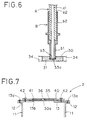
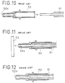
- FIGs. 10 to 14 An example of such a known thermal treatment is illustrated in Figs. 10 to 14.
- a plastic fibre 51 is passed through a ferrule 52.
- the inner surface at the tip of the ferrule is tapered to form a tapered melt zone 52a (Fig. 10).
- the tip of the fibre is applied against a hot plate 53 having a smooth face (Fig. 11).
- the heat from the plate 53 causes the tip of the plastic fibre to fuse and flow into the melt zone. In this way, the end of the plastic fibre is prevented from falling off by forming a taper, and its end section is rendered smooth (Fig. 12).
- the cooling time of the heating medium after the treatment is in some cases unnecessarily long before the plastic fibre terminal becomes solidified in the ferrule.
- an object of the present invention is to improve the thermal treatment of a plastic fibre terminal and to provide a device for that treatment so as to prevent the formation of a void between the melted plastic fibre and the ferrule, and consequently to prevent the formation of the aforementioned crack.
- the present invention provides a device for treating a plastic fiber terminal comprised of at least a cladded core and a coating, and in which a terminal portion of the cladded core is stripped.
- the coating terminal portion is passed through a ferrule that has an internal taper and is configured so as to retain the cladded core and the coating such that a tip portion of the cladded core protrudes from an end of the ferrule.
- the device is also provided with a heating medium and a heating means for heating the heating medium.
- the heating medium is held by a base frame having a central aperture and a top frame also having a central aperture, the two frames being configured for supporting the heating medium.
- the heating medium has relatively thick central area and a relatively thin rim portion.
- the central area is provided with a blind hole having a base and a sidewall.
- the blind hole is configured for receiving the terminal of the fiber such that the tip of the cladded core is applied to the base and the sidewall of the blind hole comes into contact with a corresponding sidewall portion of the ferrule.
- the rim is fixed between the base frame and the top frame by fixing means such that the central area is positioned within the aperture of the top frame.
- the relatively thick central area having the blind hole is preferably formed by a rest plate having a relatively small surface compared to the surface of a base plate, the rest plate being provided with a through hole and being superposed onto the base plate.
- the rest plate is thus detachably mounted on the base plate.
- the top frame has a step-wise structure configured so as to hold both the rest plate and the base plate.
- base of the blind hole is finished in a mirror-surface fashion.
- the heating medium can be in the form of a metal plate to ensure good thermal transfer.
- a plurality of heat evacuation vents may be provided in the heating medium.
- the device can be constructed in the form of a chamber having walls to which the base frame is fixed by fixing means, the heating means being disposed inside the chamber.
- the walls of the chamber can also be provided with at least one vent-hole.
- the heating means preferably cooperate with a positioning mechanism for selectively bringing the heating means into contact with the heating medium.
- a temperature setting mechanism may also be provided.
- the plastic fiber terminal is a plastic optical fiber.
- the invention also provides a process for treating a plastic fiber terminal comprised of at least a cladded core and a coating, the process comprising the steps of :
- the plastic fiber tip is passed through the ferrule and abutted against a face of the heating medium and, at the same time, the sidewall of the end portion of the ferrule is heated, so that the plastic fiber is heated not only in the vicinity of the tip, but also in the melt zone of the ferrule in a global and uniform way and so that the lateral part of the plastic fiber is rendered easier to melt.
- the formation of a void between the melted plastic fiber and the ferrule is effectively prevented.
- the plastic fiber thus treated is especially adapted to use in environments where temperature variations are high.
- the configuration adapted for the heating medium has advantages in that the heating and cooling thereof is globally more efficiently done and that the handling thereof becomes easier and more adapted for a wide use.
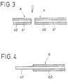
- a terminal treatment preparation process in which a plastic fibre A is initially fitted into an adapted ferrule B, shall first be explained with reference to Figs. 3 to 5.
- the ferrule is made of a heat-conductive material such as a metal.
- the plastic fibre A which is comprised of a cladded core al and a coating a2, is cut as shown in Fig. 3.
- the coating a2 is peeled off as shown in Fig. 4.
- a third step shown in Fig. 5a, the exposed cladded core al of the plastic fibre is inserted into the ferrule B so that a predetermined length L of the cladded core a1 protrudes from the tip of the ferrule (Fig. 5b).
- the ferrule B comprises a first sleeve portion b2 of relatively large diameter for supporting the coating a2 of the plastic fiber, and a second sleeve portion b1 of relatively small diameter for supporting the exposed cladded core a1 of the fibre.
- the plastic fibre is thermally processed so that the second sleeve portion b1 becomes filled with melted cladded core a1 of the plastic fibre A.
- melt zone b3 having a length D.
- the internal surface of the sleeve at the melt zone b3 forms a taper expanding towards the tip of the sleeve.
- the length L of the cladded core a1 protruding from the edge of the ferrule is determined as a function of the diameter of the cladded core al and the volume of the melt zone b3.
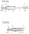
- the device 1 shown in Fig. 1 comprises a chamber 10 having an open face, a cover fixed thereon and composed of a heating medium 30, a base frame 13, a top frame 40 and a heating device disposed inside the chamber 10 (not shown in the figures).
- the heating medium 30 may be in the form of a heating plate.
- the heating medium 30 is a square or rectangular plate made of a metal having good thermal conductivity, such as copper, brass, aluminium, iron or the like. It comprises a relatively thick central area 31 and a thinner rim 32 surrounding the central area 31.
- the central, relatively thick, area 31 of the heating medium 30 has a centrally-located blind hole 33 for receiving an end portion of the ferrule B and a plurality of heat evacuation vents 34 around the blind hole 33.
- the heating medium 30 may alternatively be made of a non-metallic material having good thermal conductivity.
- the base frame 13 and the top frame 40 both have a square or rectangular central aperture (respectively 13b, 41).
- the cross-sections of the outermost portions of the heating medium rim 32 are smaller than the corresponding cross-sections of the base frame 13 and the top frame 40 but larger than the cross-section of the two apertures (13b, 41).
- the rim 32 thus lies interposed between base frame 13 and top frame 40 and is held therebetween by screws 42 such that the thicker central area 31 fits inside the aperture 41 of the top frame 40.
- the chamber 10 shown in Fig. 1 is provided with a plurality of vent-holes 11a through the sidewalls 11.
- the base frame shown in Figs. 1 and 2 is fixed by screws 13a to a flange 12 formed on the upper portion of the sidewalls 11.
- the aforementioned heating means Inside the chamber 10 there are provided the aforementioned heating means and an elevator mechanism (not shown in the figures) which enables the heating means to approach to or move away from the heating medium 30. These movements can be operated from the outside through a positioning button 21 which protrudes from the sidewalls 11 of the chamber 10.
- the aforementioned heating means is provided with a temperature setting screw (not shown in the figures), which can be accessed by inserting a screwdriver through an access hole 14 formed in a sidewall 11 of the chamber 10.
- the base 33a of the blind hole 33 functions as a pressing surface to carry out the treatment on the terminal of a plastic optical fibre passed through a ferrule.
- the base of the blind hole is preferably finished in a mirror-face fashion so as to produce a smooth end face of the plastic optical fibre.
- the heating medium 30 is heated by operating the heater positioning button 21 so that the heating means is put into the contact with the underside of the heating medium 30.
- the end portion of the ferrule B containing a protruding cladded core al is inserted into the blind hole 33 and pressed, the end portion of the cladded core al of the plastic optical fibre A is heated not only by its end face, but also by the wall portions of the ferule B. Accordingly, the portion which is intended to correspond to the melt zone b3 fuses uniformly. In this way, the melt zone b3 is filled completely without producing a void and at the same time the mirror-face finish of the base 3a is imprinted on the end face of the cladded core al of the plastic optical fibre A.
- the heating means is preset by the temperature adjusting screw so that treatment temperature settles at the level of 180°C.
- the heating means is moved away from the under-side of the heating medium 30 by operation of the heater positioning button 21 and the heating medium 30 is left to stand until the temperature decreases to below 120°C, i.e. the temperature at which molten plastic of the optical fibre solidifies.
- the present device is provided with a number of heat evacuation vents 34 in the heating medium 30.
- Figs. 7, 8 and 9 show other embodiments of the invention.
- the terminal treatment device 2 and 3 in these figures have approximately the same construction as in the preceding embodiment, the same construction elements are referred to by the same numbers. Only different elements are explained in the following part of the description.
- the terminal treatment device 2 shown in figure 7 has a heating medium 30 which comprises two superposed plates.
- a base plate 30a is relatively thin and of uniform thickness. Its topmost side is finished in a mirror-face.
- the base plate 30a is fixed on a base frame 13 of a chamber 10 by a top frame 40 and screws 42.
- a rest plate 35 made of a material having good thermal conductivity, is fitted into the aperture 41 of the top frame 40 and is disposed on the base plate 30a.
- the central portion of the rest plate 35 is provided with a through hole 36 into which the tip of ferrule can be inserted.
- the upper side of the base plate 30a which has a face with a mirror-like finish, is accessible through the hole.
- the plastic optical fibre prepared as described is passed through a ferrule so that the tip of the cladded core protrudes a little from the ferrule B.
- the tip portion of the ferrule is fitted into the through hole 36 in the rest plate 35 and pressed onto the upper face of the base plate 30a, it is also heated by the contact between its sidewalls and confronting side wall of the hole 36. In this way, an effective terminal treatment can be achieved in the same way as in the preceding embodiment.
- the rest plate 35 is simply superposed to a base plate 30a, so that the rest plate 35 can easily be removed.
- the base plate 30a may be used as in a classical terminal treatment device, if needs be.
- Another advantage of the above-described construction is that it can easily be derived from an existing device simply by superposing the rest plate 35 on the heating medium of the known device which serves as a base plate.
- the rest plate 35 is also provided with a heat evacuation vent such as in the present example, the natural cooling time may be shortened. This possibility is not shown in Figs. 7 to 9.
- Figs. 8 and 9 show a variant of the terminal treatment device 2 illustrated in Fig. 7.
- the device 3 differs from the one of figure 7 by the fact that the rest plate clamp 43 is integrally formed with the top frame 40 and that the rest plate 35 and the base plate 30a are together inserted and fixed between the top frame 40 and the base frame 13.
- the rest plate 35 is fixed in a detachable way, a known terminal treatment device can be transformed into the terminal treatment device according to the present invention, and vice versa.
- the rest plate 35 in the terminal treatment device 3 may of course be provided with some form of heat evacuation vent to shorten the natural cooling time.
- the present invention involves first passing a plastic optical fibre through a ferrule and thereafter inserting and pressing the end of the fibre into a blind hole formed in a heating medium.
- the plastic optical fibre is then heated not only by the end face but also by its sidewalls, so that the corresponding portion fuses uniformly and fills the melt zone without forming a void.
- the device can also be used as a classical terminal treatment device after removal of the rest plate.
- This type of device has a large utility and is easier to clean. This is especially true in the type of device where the rest plate is fitted against the frame, for in this case the setting and removal of the deposit plate are very easy, and working efficiency is thus considerably improved.
Applications Claiming Priority (3)
| Application Number | Priority Date | Filing Date | Title |
|---|---|---|---|
| JP6143514A JP2947073B2 (ja) | 1994-06-24 | 1994-06-24 | プラスチック光ファイバの端面処理装置 |
| JP14351494 | 1994-06-24 | ||
| JP143514/94 | 1994-06-24 |
Publications (2)
| Publication Number | Publication Date |
|---|---|
| EP0689070A1 true EP0689070A1 (fr) | 1995-12-27 |
| EP0689070B1 EP0689070B1 (fr) | 2002-08-28 |
Family
ID=15340516
Family Applications (1)
| Application Number | Title | Priority Date | Filing Date |
|---|---|---|---|
| EP95401490A Expired - Lifetime EP0689070B1 (fr) | 1994-06-24 | 1995-06-23 | Dispositif de traitement de l'extrémité pour une fibre en plastique |
Country Status (4)
| Country | Link |
|---|---|
| US (1) | US5770132A (fr) |
| EP (1) | EP0689070B1 (fr) |
| JP (1) | JP2947073B2 (fr) |
| DE (1) | DE69527891T2 (fr) |
Cited By (10)
| Publication number | Priority date | Publication date | Assignee | Title |
|---|---|---|---|---|
| WO2001044846A2 (fr) * | 1999-12-15 | 2001-06-21 | Scc Special Communication Cables Gmbh & Co Kg | Procede pour assembler une fibre optique et un connecteur |
| WO2001096923A1 (fr) * | 2000-06-12 | 2001-12-20 | Krone Gmbh | Ensemble et procede a utiliser dans la terminaison d'une ou de plusieurs fibres optiques |
| EP1227348A2 (fr) * | 2001-01-17 | 2002-07-31 | Autonetworks Technologies, Ltd. | Procédé de fabrication pour une extrémité d'une fibre optique et dispositif de traitement d'extrémité d'une fibre optique |
| US7530746B2 (en) | 2007-04-13 | 2009-05-12 | Abc Telecommunications, Inc. | Field termination connector with shaped adhesive pre-form |
| US7534050B2 (en) | 2007-04-13 | 2009-05-19 | Adc Telecommunications, Inc. | Field terminatable fiber optic connector assembly |
| US7676134B2 (en) | 2007-04-13 | 2010-03-09 | Adc Telecommunications, Inc. | Field termination kit |
| US8083416B2 (en) | 2007-11-30 | 2011-12-27 | Adc Telecommunications, Inc. | Hybrid fiber/copper connector system and method |
| US8636425B2 (en) | 2011-03-15 | 2014-01-28 | Adc Telecommunications, Inc. | Fiber optic connector |
| US9176285B2 (en) | 2012-05-03 | 2015-11-03 | Adc Telecommunications, Inc. | Fiber optic connector |
| US9268102B2 (en) | 2012-02-07 | 2016-02-23 | Tyco Electronics Raychem Bvba | Cable termination assembly and method for connectors |
Families Citing this family (9)
| Publication number | Priority date | Publication date | Assignee | Title |
|---|---|---|---|---|
| US6636672B1 (en) * | 1999-07-07 | 2003-10-21 | Fitel Usa Corp | System comprising plastic optical fiber |
| JP2001021732A (ja) | 1999-07-08 | 2001-01-26 | Alps Electric Co Ltd | プラスチック光ファイバ端面加工方法及びその加工装置 |
| US6883975B2 (en) * | 2001-02-12 | 2005-04-26 | Polymicro Technologies, Inc. | Connector ferrule and method of sealing |
| US7003985B2 (en) * | 2001-10-01 | 2006-02-28 | Swain Robert F | Method and apparatus for removing polymeric coatings from optical fiber in a non-oxidizing environment |
| US6436198B1 (en) * | 2001-10-01 | 2002-08-20 | Robert F. Swain | Method and apparatus for removing polymeric coatings from optical fiber |
| US7309167B2 (en) * | 2005-02-22 | 2007-12-18 | Innovaquartz Inc. | High energy fiber terminations and methods |
| CN101606091B (zh) * | 2007-09-07 | 2012-07-04 | 住友电气工业株式会社 | 保护套管以及用于制造保护套管的装置和方法 |
| US9888837B2 (en) * | 2011-11-28 | 2018-02-13 | I-Tek Medical Solutions, Inc. | Fiber optic illumination device and method of manufacturing |
| CN111108420A (zh) | 2017-09-29 | 2020-05-05 | 康普技术有限责任公司 | 用于光纤连接器的快速处理的传导加热组件和方法 |
Citations (9)
| Publication number | Priority date | Publication date | Assignee | Title |
|---|---|---|---|---|
| JPS58187903A (ja) | 1982-04-28 | 1983-11-02 | Mitsubishi Rayon Co Ltd | 導光体の製造方法 |
| JPS60156007A (ja) * | 1984-01-25 | 1985-08-16 | Matsushita Electric Works Ltd | 光フアイバ端面処理用治具 |
| EP0152225A2 (fr) * | 1984-01-30 | 1985-08-21 | The Furukawa Electric Co., Ltd. | Cordon d'un fibre optique plastique avec un bout |
| JPS61258203A (ja) * | 1985-05-13 | 1986-11-15 | Asahi Chem Ind Co Ltd | プラスチツク光フアイバの端面処理方法 |
| JPH01221704A (ja) * | 1988-02-29 | 1989-09-05 | Toray Ind Inc | プラスチック光ファイバの端面処理装置 |
| EP0393601A2 (fr) * | 1989-04-18 | 1990-10-24 | The Whitaker Corporation | Support pour un dispositif de traitement d'extrémité d'une fibre optique |
| JPH052111A (ja) * | 1991-06-25 | 1993-01-08 | Sony Corp | 光ケーブルの端面加工方法 |
| DE9309432U1 (de) * | 1993-06-21 | 1993-08-26 | Siemens Ag | Elektrisches Gerät |
| JPH0613428A (ja) | 1992-06-24 | 1994-01-21 | Matsushita Electric Ind Co Ltd | 半導体装置の製造方法 |
Family Cites Families (10)
| Publication number | Priority date | Publication date | Assignee | Title |
|---|---|---|---|---|
| GB1556046A (en) * | 1975-07-09 | 1979-11-21 | Elliott Bros | Optical-fibre cables |
| JPS6015241B2 (ja) * | 1979-03-13 | 1985-04-18 | 三菱レイヨン株式会社 | 光学繊維の端面加工方法 |
| US4510005A (en) * | 1982-09-28 | 1985-04-09 | Allied Corporation | Method and apparatus for reshaping and polishing an end face of an optical fiber |
| JPS59118433A (ja) * | 1982-12-27 | 1984-07-09 | Furukawa Electric Co Ltd:The | プラスチツクフアイバの端面処理方法 |
| IT1212960B (it) * | 1983-10-25 | 1989-12-07 | Russo Vera Firenze Via D Panch | Metodo di fabbricazione per terminazioni a microlente per fibre ottiche,particolarmente per uso biomedico e/o chirurgico, e dispositivo per effettuare detto metodo |
| JPH0233005A (ja) * | 1988-07-21 | 1990-02-02 | Kao Corp | 物品の取り出し方法及びその装置 |
| CA2052110A1 (fr) * | 1990-11-16 | 1992-05-17 | Eric C. Angel | Terminaison de fibre optique |
| JPH0667032A (ja) * | 1992-08-24 | 1994-03-11 | Japan Automat Mach Co Ltd | 光ファイバーの端面処理方法 |
| JPH06118276A (ja) * | 1992-10-07 | 1994-04-28 | Mitsubishi Rayon Co Ltd | 光ファイバコードの端面加工法 |
| JPH07218731A (ja) * | 1994-02-07 | 1995-08-18 | Sumitomo Wiring Syst Ltd | プラスチックファイバの端面処理方法及び端面処理装置 |
-
1994
- 1994-06-24 JP JP6143514A patent/JP2947073B2/ja not_active Expired - Fee Related
-
1995
- 1995-06-23 EP EP95401490A patent/EP0689070B1/fr not_active Expired - Lifetime
- 1995-06-23 DE DE69527891T patent/DE69527891T2/de not_active Expired - Fee Related
- 1995-06-23 US US08/494,267 patent/US5770132A/en not_active Expired - Lifetime
Patent Citations (9)
| Publication number | Priority date | Publication date | Assignee | Title |
|---|---|---|---|---|
| JPS58187903A (ja) | 1982-04-28 | 1983-11-02 | Mitsubishi Rayon Co Ltd | 導光体の製造方法 |
| JPS60156007A (ja) * | 1984-01-25 | 1985-08-16 | Matsushita Electric Works Ltd | 光フアイバ端面処理用治具 |
| EP0152225A2 (fr) * | 1984-01-30 | 1985-08-21 | The Furukawa Electric Co., Ltd. | Cordon d'un fibre optique plastique avec un bout |
| JPS61258203A (ja) * | 1985-05-13 | 1986-11-15 | Asahi Chem Ind Co Ltd | プラスチツク光フアイバの端面処理方法 |
| JPH01221704A (ja) * | 1988-02-29 | 1989-09-05 | Toray Ind Inc | プラスチック光ファイバの端面処理装置 |
| EP0393601A2 (fr) * | 1989-04-18 | 1990-10-24 | The Whitaker Corporation | Support pour un dispositif de traitement d'extrémité d'une fibre optique |
| JPH052111A (ja) * | 1991-06-25 | 1993-01-08 | Sony Corp | 光ケーブルの端面加工方法 |
| JPH0613428A (ja) | 1992-06-24 | 1994-01-21 | Matsushita Electric Ind Co Ltd | 半導体装置の製造方法 |
| DE9309432U1 (de) * | 1993-06-21 | 1993-08-26 | Siemens Ag | Elektrisches Gerät |
Non-Patent Citations (4)
| Title |
|---|
| PATENT ABSTRACTS OF JAPAN vol. 11, no. 109 (P - 564)<2556> 7 April 1987 (1987-04-07) * |
| PATENT ABSTRACTS OF JAPAN vol. 13, no. 537 (P - 968) 5 September 1989 (1989-09-05) * |
| PATENT ABSTRACTS OF JAPAN vol. 17, no. 258 (P - 1540) 8 January 1993 (1993-01-08) * |
| PATENT ABSTRACTS OF JAPAN vol. 9, no. 329 (P - 416) 16 August 1985 (1985-08-16) * |
Cited By (32)
| Publication number | Priority date | Publication date | Assignee | Title |
|---|---|---|---|---|
| WO2001044846A3 (fr) * | 1999-12-15 | 2001-11-29 | Scc Special Comm Cables Gmbh | Procede pour assembler une fibre optique et un connecteur |
| WO2001044846A2 (fr) * | 1999-12-15 | 2001-06-21 | Scc Special Communication Cables Gmbh & Co Kg | Procede pour assembler une fibre optique et un connecteur |
| USRE43542E1 (en) | 2000-06-12 | 2012-07-24 | Adc Gmbh | Assembly and method for use in terminating an optical fiber or fibers |
| WO2001096923A1 (fr) * | 2000-06-12 | 2001-12-20 | Krone Gmbh | Ensemble et procede a utiliser dans la terminaison d'une ou de plusieurs fibres optiques |
| US6811323B2 (en) | 2000-06-12 | 2004-11-02 | Krone Gmbh | Assembly and method for use in terminating an optical fiber or fibers |
| KR100851732B1 (ko) * | 2000-06-12 | 2008-08-11 | 에이디씨 게엠베하 | 광섬유의 단부처리에 사용되는 조립체와 방법 |
| EP1227348A2 (fr) * | 2001-01-17 | 2002-07-31 | Autonetworks Technologies, Ltd. | Procédé de fabrication pour une extrémité d'une fibre optique et dispositif de traitement d'extrémité d'une fibre optique |
| EP1227348A3 (fr) * | 2001-01-17 | 2004-03-24 | Autonetworks Technologies, Ltd. | Procédé de fabrication pour une extrémité d'une fibre optique et dispositif de traitement d'extrémité d'une fibre optique |
| US8944702B2 (en) | 2007-04-13 | 2015-02-03 | Adc Telecommunications, Inc. | Fiber optic connector with fiber take-up region |
| US9389372B2 (en) | 2007-04-13 | 2016-07-12 | Commscope Technologies Llc | Fiber optic connector with fiber take-up region |
| US7766556B2 (en) | 2007-04-13 | 2010-08-03 | Adc Telecommunications, Inc. | Field terminatable fiber optic connector assembly |
| US7929819B2 (en) | 2007-04-13 | 2011-04-19 | Adc Telecommunications, Inc. | Field termination kit |
| US7534050B2 (en) | 2007-04-13 | 2009-05-19 | Adc Telecommunications, Inc. | Field terminatable fiber optic connector assembly |
| US10175429B2 (en) | 2007-04-13 | 2019-01-08 | Commscope Technologies Llc | Fiber optic connector with fiber take-up region |
| US7530746B2 (en) | 2007-04-13 | 2009-05-12 | Abc Telecommunications, Inc. | Field termination connector with shaped adhesive pre-form |
| US7676134B2 (en) | 2007-04-13 | 2010-03-09 | Adc Telecommunications, Inc. | Field termination kit |
| US8083416B2 (en) | 2007-11-30 | 2011-12-27 | Adc Telecommunications, Inc. | Hybrid fiber/copper connector system and method |
| US8678666B2 (en) | 2007-11-30 | 2014-03-25 | Adc Telecommunications, Inc. | Hybrid fiber/copper connector system and method |
| US9841566B2 (en) | 2011-03-15 | 2017-12-12 | Commscope Technologies Llc | Fiber optic connector |
| US10146011B2 (en) | 2011-03-15 | 2018-12-04 | Commscope Technologies Llc | Fiber optic connector |
| US11782224B2 (en) | 2011-03-15 | 2023-10-10 | Commscope Technologies Llc | Fiber optic connector |
| US9500813B2 (en) | 2011-03-15 | 2016-11-22 | Commscope Technologies Llc | Fiber optic connector |
| US10859771B2 (en) | 2011-03-15 | 2020-12-08 | Commscope Technologies Llc | Fiber optic connector |
| US10495822B2 (en) | 2011-03-15 | 2019-12-03 | Commscope Technologies Llc | Fiber optic connector |
| US9151904B2 (en) | 2011-03-15 | 2015-10-06 | Adc Telecommunications, Inc. | Fiber optic connector |
| US8636425B2 (en) | 2011-03-15 | 2014-01-28 | Adc Telecommunications, Inc. | Fiber optic connector |
| US10036859B2 (en) | 2012-02-07 | 2018-07-31 | CommScope Connectivity Belgium BVBA | Cable termination assembly and method for connectors |
| US9268102B2 (en) | 2012-02-07 | 2016-02-23 | Tyco Electronics Raychem Bvba | Cable termination assembly and method for connectors |
| US9625660B2 (en) | 2012-02-07 | 2017-04-18 | CommScope Connectivity Belgium BVBA | Cable termination assembly and method for connectors |
| US10371899B2 (en) | 2012-05-03 | 2019-08-06 | Commscope Technologies Llc | Fiber optic connector |
| US9638869B2 (en) | 2012-05-03 | 2017-05-02 | Commscope Technologies Llc | Fiber optic connector |
| US9176285B2 (en) | 2012-05-03 | 2015-11-03 | Adc Telecommunications, Inc. | Fiber optic connector |
Also Published As
| Publication number | Publication date |
|---|---|
| JPH085867A (ja) | 1996-01-12 |
| JP2947073B2 (ja) | 1999-09-13 |
| DE69527891T2 (de) | 2003-05-08 |
| EP0689070B1 (fr) | 2002-08-28 |
| US5770132A (en) | 1998-06-23 |
| DE69527891D1 (de) | 2002-10-02 |
Similar Documents
| Publication | Publication Date | Title |
|---|---|---|
| EP0689070B1 (fr) | Dispositif de traitement de l'extrémité pour une fibre en plastique | |
| US5778125A (en) | Optical fiber terminations | |
| JPH075347A (ja) | 光部品をカプセル封緘する方法およびカプセル封緘された光部品 | |
| US5044721A (en) | Holder for optical fiber end-processing device | |
| EP0666486A1 (fr) | Procédé de traitement de l'extrémité d'une fibre en plastique et dispositif pour ce traitement | |
| US4781775A (en) | Coplanar die to substrate bond method | |
| JPS61284710A (ja) | 光フアイバ端末にコネクタを固着する方法 | |
| JPH03504906A (ja) | 可撓性同軸ケーブルと口金のはんだ付け方法 | |
| JP3234166B2 (ja) | 鋳造光ファイバプリフォーム中のコアホール作製の方法及び装置 | |
| US3017483A (en) | Method of induction welding of stranded aluminum cable | |
| JPH11264911A (ja) | 光ファイバ束の製造方法 | |
| US2259281A (en) | Method and apparatus for soldering connections to cable sheaths | |
| JP3869986B6 (ja) | 光ファイバー束の製造方法、それにより製造された光ファイバー束及びその方法の実施装置 | |
| JPH0632680Y2 (ja) | 半導体製造装置の加熱炉 | |
| KR100188818B1 (ko) | 양초제조장치 및 그 방법 | |
| JP2004012878A (ja) | 光ファイバ芯線の端面加工方法 | |
| JPS6021320A (ja) | 微小鋼材部品の局部焼入れ方法 | |
| SU694926A1 (ru) | Способ изолировани сростка многожильных кабелей | |
| JPS58108502A (ja) | 光フアイバの周側面処理方法 | |
| JPH06288824A (ja) | 光ファイバセンサヘッド | |
| KR19990079519A (ko) | 평면음극선관의 패널과 펀넬 분리방법 | |
| JP2000321462A (ja) | 線材補強用スリーブの加熱方法 | |
| JPH07120731B2 (ja) | 半導体装置の製造方法 | |
| JP2001194556A (ja) | 光ファイバアレイ及びその製造方法 | |
| JPH0798004B2 (ja) | 根付けの製造方法 |
Legal Events
| Date | Code | Title | Description |
|---|---|---|---|
| PUAI | Public reference made under article 153(3) epc to a published international application that has entered the european phase |
Free format text: ORIGINAL CODE: 0009012 |
|
| 17P | Request for examination filed |
Effective date: 19950630 |
|
| AK | Designated contracting states |
Kind code of ref document: A1 Designated state(s): DE FR GB |
|
| 17Q | First examination report despatched |
Effective date: 20000829 |
|
| GRAG | Despatch of communication of intention to grant |
Free format text: ORIGINAL CODE: EPIDOS AGRA |
|
| GRAG | Despatch of communication of intention to grant |
Free format text: ORIGINAL CODE: EPIDOS AGRA |
|
| GRAH | Despatch of communication of intention to grant a patent |
Free format text: ORIGINAL CODE: EPIDOS IGRA |
|
| GRAH | Despatch of communication of intention to grant a patent |
Free format text: ORIGINAL CODE: EPIDOS IGRA |
|
| GRAA | (expected) grant |
Free format text: ORIGINAL CODE: 0009210 |
|
| AK | Designated contracting states |
Kind code of ref document: B1 Designated state(s): DE FR GB |
|
| REG | Reference to a national code |
Ref country code: GB Ref legal event code: FG4D |
|
| REF | Corresponds to: |
Ref document number: 69527891 Country of ref document: DE Date of ref document: 20021002 |
|
| ET | Fr: translation filed | ||
| PLBE | No opposition filed within time limit |
Free format text: ORIGINAL CODE: 0009261 |
|
| STAA | Information on the status of an ep patent application or granted ep patent |
Free format text: STATUS: NO OPPOSITION FILED WITHIN TIME LIMIT |
|
| 26N | No opposition filed |
Effective date: 20030530 |
|
| PGFP | Annual fee paid to national office [announced via postgrant information from national office to epo] |
Ref country code: FR Payment date: 20060608 Year of fee payment: 12 |
|
| PGFP | Annual fee paid to national office [announced via postgrant information from national office to epo] |
Ref country code: DE Payment date: 20060615 Year of fee payment: 12 |
|
| PGFP | Annual fee paid to national office [announced via postgrant information from national office to epo] |
Ref country code: GB Payment date: 20060621 Year of fee payment: 12 |
|
| GBPC | Gb: european patent ceased through non-payment of renewal fee |
Effective date: 20070623 |
|
| REG | Reference to a national code |
Ref country code: FR Ref legal event code: ST Effective date: 20080229 |
|
| PG25 | Lapsed in a contracting state [announced via postgrant information from national office to epo] |
Ref country code: DE Free format text: LAPSE BECAUSE OF NON-PAYMENT OF DUE FEES Effective date: 20080101 |
|
| PG25 | Lapsed in a contracting state [announced via postgrant information from national office to epo] |
Ref country code: GB Free format text: LAPSE BECAUSE OF NON-PAYMENT OF DUE FEES Effective date: 20070623 |
|
| PG25 | Lapsed in a contracting state [announced via postgrant information from national office to epo] |
Ref country code: FR Free format text: LAPSE BECAUSE OF NON-PAYMENT OF DUE FEES Effective date: 20070702 |