EP0685643A2 - Ventilnadel für ein elektromagnetisch betätigbares Ventil - Google Patents
Ventilnadel für ein elektromagnetisch betätigbares Ventil Download PDFInfo
- Publication number
- EP0685643A2 EP0685643A2 EP95105247A EP95105247A EP0685643A2 EP 0685643 A2 EP0685643 A2 EP 0685643A2 EP 95105247 A EP95105247 A EP 95105247A EP 95105247 A EP95105247 A EP 95105247A EP 0685643 A2 EP0685643 A2 EP 0685643A2
- Authority
- EP
- European Patent Office
- Prior art keywords
- section
- valve
- valve needle
- armature
- closing member
- Prior art date
- Legal status (The legal status is an assumption and is not a legal conclusion. Google has not performed a legal analysis and makes no representation as to the accuracy of the status listed.)
- Granted
Links
Images


Classifications
-
- F—MECHANICAL ENGINEERING; LIGHTING; HEATING; WEAPONS; BLASTING
- F02—COMBUSTION ENGINES; HOT-GAS OR COMBUSTION-PRODUCT ENGINE PLANTS
- F02M—SUPPLYING COMBUSTION ENGINES IN GENERAL WITH COMBUSTIBLE MIXTURES OR CONSTITUENTS THEREOF
- F02M61/00—Fuel-injectors not provided for in groups F02M39/00 - F02M57/00 or F02M67/00
- F02M61/16—Details not provided for in, or of interest apart from, the apparatus of groups F02M61/02 - F02M61/14
- F02M61/168—Assembling; Disassembling; Manufacturing; Adjusting
-
- F—MECHANICAL ENGINEERING; LIGHTING; HEATING; WEAPONS; BLASTING
- F02—COMBUSTION ENGINES; HOT-GAS OR COMBUSTION-PRODUCT ENGINE PLANTS
- F02M—SUPPLYING COMBUSTION ENGINES IN GENERAL WITH COMBUSTIBLE MIXTURES OR CONSTITUENTS THEREOF
- F02M51/00—Fuel-injection apparatus characterised by being operated electrically
- F02M51/06—Injectors peculiar thereto with means directly operating the valve needle
- F02M51/061—Injectors peculiar thereto with means directly operating the valve needle using electromagnetic operating means
- F02M51/0625—Injectors peculiar thereto with means directly operating the valve needle using electromagnetic operating means characterised by arrangement of mobile armatures
- F02M51/0664—Injectors peculiar thereto with means directly operating the valve needle using electromagnetic operating means characterised by arrangement of mobile armatures having a cylindrically or partly cylindrically shaped armature, e.g. entering the winding; having a plate-shaped or undulated armature entering the winding
- F02M51/0671—Injectors peculiar thereto with means directly operating the valve needle using electromagnetic operating means characterised by arrangement of mobile armatures having a cylindrically or partly cylindrically shaped armature, e.g. entering the winding; having a plate-shaped or undulated armature entering the winding the armature having an elongated valve body attached thereto
-
- F—MECHANICAL ENGINEERING; LIGHTING; HEATING; WEAPONS; BLASTING
- F02—COMBUSTION ENGINES; HOT-GAS OR COMBUSTION-PRODUCT ENGINE PLANTS
- F02M—SUPPLYING COMBUSTION ENGINES IN GENERAL WITH COMBUSTIBLE MIXTURES OR CONSTITUENTS THEREOF
- F02M2200/00—Details of fuel-injection apparatus, not otherwise provided for
- F02M2200/80—Fuel injection apparatus manufacture, repair or assembly
- F02M2200/8046—Fuel injection apparatus manufacture, repair or assembly the manufacture involving injection moulding, e.g. of plastic or metal
-
- Y—GENERAL TAGGING OF NEW TECHNOLOGICAL DEVELOPMENTS; GENERAL TAGGING OF CROSS-SECTIONAL TECHNOLOGIES SPANNING OVER SEVERAL SECTIONS OF THE IPC; TECHNICAL SUBJECTS COVERED BY FORMER USPC CROSS-REFERENCE ART COLLECTIONS [XRACs] AND DIGESTS
- Y10—TECHNICAL SUBJECTS COVERED BY FORMER USPC
- Y10S—TECHNICAL SUBJECTS COVERED BY FORMER USPC CROSS-REFERENCE ART COLLECTIONS [XRACs] AND DIGESTS
- Y10S239/00—Fluid sprinkling, spraying, and diffusing
- Y10S239/90—Electromagnetically actuated fuel injector having ball and seat type valve
Definitions
- the invention relates to a valve needle for an electromagnetically actuated valve according to the preamble of the main claim.
- a valve needle for an electromagnetically actuated valve is already known, which consists of an armature section, a valve closing member section and a tubular valve sleeve section connecting the armature section with the valve closing member section.
- the individual sections represent separate parts manufactured separately from one another, which are only connected to one another using joining processes.
- valve needle for an electromagnetically actuated valve which consists of an armature section, a valve closing member section and a valve sleeve section connecting the armature section with the valve closing member section.
- the armature section is connected to one end of the valve sleeve section by means of a first welded connection and the valve closing member section is connected to the other end of the Valve sleeve section connected by a second weld.
- Two welding operations are therefore required to produce the valve needle, which lead to a relatively complex and expensive manufacture of the valve needle.
- a valve needle for an electromagnetically actuated valve consists of a one-piece tubular actuating part consisting of an armature section and a valve sleeve section by injection molding and subsequent sintering according to the metal injection molding process (MIM). to manufacture.
- the actuating part is then connected to a valve closing element section by means of a welded connection.
- a continuous inner longitudinal opening is provided in the armature section and valve sleeve section, in which fuel can flow in the direction of the valve closing member section, which then emerges from the valve sleeve section through transverse openings near the valve closing section.
- valve needle according to the invention with the characterizing features of the main claim has the advantage that it can be produced in a particularly simple and inexpensive manner.
- the "valve sleeve section" is no longer a sleeve, but is rather solid as a valve needle section between the armature section and valve closing member section, so that the tool for producing the armature section and valve needle section Actuating part can be constructed very simply, since no cross slide tools are required to create cross openings. This completely eliminates the risk of burrs that previously existed in the transverse openings due to production.
- At least two axially extending flow channels in the interior of the armature section ensure that the fuel flows freely in the direction of the valve seat. The fuel emerging from the flow channels can flow along the outer circumference of the valve needle section without deflections.
- valve needle is obtained when it is manufactured with the armature section, the valve needle section and the valve closing member section as a molded part according to the metal injection molding process.
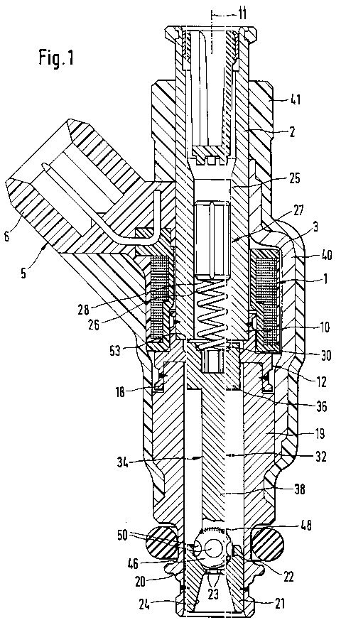
- FIG. 1 shows a fuel injector with a valve needle according to the invention
- FIG. 2 shows a plan view of the valve needle
- FIG. 3 shows a section along the line III-III in FIG. 2
- FIG. 4 shows a section along the line IV-IV in FIG. 2.
- the electromagnetically actuated valve shown in FIG. 1, for example, in the form of an injection valve for fuel injection systems of mixed-compression spark-ignition internal combustion engines has a core 2, which is surrounded by a magnet coil 1 and serves as a fuel inlet connector.
- the magnet coil 1 with a coil body 3 is, for. B. with a plastic extrusion 5, at the same time an electrical connector 6 is molded.
- a tubular, metallic intermediate part 12 is connected, for example by welding, concentrically to a longitudinal valve axis 11 and partially overlaps the core end 10 axially.
- the intermediate part 12 is at its core 2 facing away End provided with a lower cylinder section 18 which engages over a tubular nozzle carrier 19 and is tightly connected thereto, for example by welding.
- a cylindrical valve seat body 21 is tightly mounted by welding in a through hole 20 which runs concentrically to the valve longitudinal axis 11.
- the valve seat body 21 has the solenoid 1 facing a fixed valve seat 22, downstream of which in the valve seat body 21 z. B. two spray openings 23 are formed. Downstream of the spray openings 23, the valve seat body 21 has a treatment bore 24 which widens in the shape of a truncated cone in the flow direction.
- a tubular adjusting bushing 27 is pressed into a stepped flow bore 25 of the core 2 that runs concentrically to the valve longitudinal axis 11 in order to adjust the spring force of a return spring 26.
- the press-in depth of the adjusting bush 27 into the flow bore 25 of the core 2 determines the spring force of the return spring 26 and thus also influences the dynamic fuel quantity emitted during the opening and closing stroke of the valve.
- the return spring 26 With its end facing away from the adjusting bush 27, the return spring 26 is supported on a holding shoulder 30 of an actuating part 32 arranged concentrically to the longitudinal valve axis 11, while the return spring 26 rests with its other end on a lower end face 28 of the adjusting bush 27.
- the actuating part 32 is part of a valve needle 34 and itself consists of an armature section 36 facing the core 2 and interacting with the core 2 and the magnet coil 1 and a solid valve needle section 38 extending towards the valve seat body 21 Arranged downstream of the valve needle section 38, for example spherical valve closing member section 46, the actuating part 32 forms the valve needle 34.
- the spherical valve closing member section 46 is, for example, firmly and tightly connected to the actuating part 32 by means of a welded connection 48 achieved by laser welding.
- valve needle section 38 of the actuating part 32 has at its downstream end facing away from the holding shoulder 30 an end-side, for example conical or spherical, spherical-shaped contact surface 49
- Valve needle section 38 and the valve closing member section 46 generally have a smaller diameter than the armature section 36.
- The, for example, spherical valve closing member section 46 has z. B. four circular flats 50, which facilitate the flow of fuel in the direction of the valve seat 22 of the valve seat body 21.
- the actuating part 32 is explained in more detail below with reference to FIGS. 2 to 4.
- the magnet coil 1 is at least partially surrounded by at least one guiding element 40, which is designed as a bracket and serves as a ferromagnetic element, which bears with its one end on the core 2 and with its other end on the nozzle carrier 19 and with these z. B. is connected by welding or soldering. A part of the valve is enclosed by a plastic sheath 41, which extends from the core 2 in the axial direction over the magnet coil 1 with connector 6 and the at least one guide element 40.
- the actuating part 32 consisting of the armature section 36 and the valve needle section 38 and optionally also the valve closing member section 46 of the valve needle 34 are produced by injection molding and subsequent sintering.
- the already known and also referred to as metal injection molding (MIM) process comprises the production of molded parts from a metal powder with a binder, for. B. a plastic binder, for example on conventional plastic injection molding machines and the subsequent removal of the binder and sintering the remaining metal powder structure.
- the composition of the metal powder can be matched in a simple manner to optimal magnetic properties of the actuating part 32 consisting of the armature section 36 and the valve needle section 38 or the valve closing member section 46.
- FIG. 2 shows a top view of the actuating part 32 or the armature section 36 from an upstream end face 53 facing the core 2.
- This top view clearly shows that the holding shoulder 30, which is axially lower than the end face 53 and has a smaller diameter than the end face 53, for supporting the return spring 26 is interrupted by, for example, three or four axial grooves 55 running axially, i.e. in the direction of the valve longitudinal axis 11 is.
- the return spring 26 is consequently only in contact with the regions of the holding shoulder 30 which remain annular between the axial grooves 55.
- the axial grooves 55 extend over the entire remaining length of the armature section 36 and serve to allow the fuel coming from the flow bore 25 of the core 2 to flow unhindered in the direction of the valve seat 22.
- FIGS. 3 and 4 are representations of sections along the lines III-III and IV-IV in FIG. 2, FIG. 3 showing a section that runs through the solid material from the holding shoulder 30 in the axial direction of the anchor section 36, and FIG. 4 illustrates a section through two axial grooves 55 in the armature section 36.
- a central inner, blind hole-like recess 57 extends, for example, with the same diameter as the solid valve needle section 38, starting from the holding shoulder 30 in the anchor section 36 downstream to an end face 56 of the valve needle section 38 opposite the contact surface 49 and is directly connected to the axial grooves 55.
- the valve needle section 38 projects partially into the armature section 36, i. H.
- the upstream end face 56 of the valve needle section 38 facing the holding shoulder 30 lies further upstream than a shoulder 58, which results on the outer contour of the actuating part 32, from the armature section 36 to the valve needle section 38, at which the axial grooves 55 end.
- the axial grooves 55 no longer represent grooves, but due to the complete material encapsulation, axial flow channels 60 adjoining one another in alignment partially as a wall film of the valve needle section 38, since the inner boundary of each flow channel 60 is given by the valve needle section 38.
- the injection point 62 during injection molding of the actuating part 32 can be provided such that it lies in a recess 61 at the downstream end of the actuating part 32.
- the valve closing member section 46 Before the valve closing member section 46 is attached, it must then not be removed, which guarantees a cost reduction. Rather, after the spherical valve closing member section 46 has been welded onto the contact surface 49 of the actuating part 32, the depression 61 with the injection point 62 is hermetically sealed, so that there are no negative effects from this area.
- the MIM method can be used even more easily if, instead of already known tubular actuation parts, the actuation parts 32 according to the invention are produced with a solid valve needle section 38. The introduction of transverse openings in the region of the valve needle section 38 is in fact completely eliminated.
- valve needle 34 with the armature section 36, valve needle section 38 and valve closing member section 46 is produced as a molded part according to the metal injection molding method. This eliminates the need to weld the valve closing member section 46 to the valve needle section 38.
Landscapes
- Engineering & Computer Science (AREA)
- Chemical & Material Sciences (AREA)
- Combustion & Propulsion (AREA)
- Mechanical Engineering (AREA)
- General Engineering & Computer Science (AREA)
- Physics & Mathematics (AREA)
- Electromagnetism (AREA)
- Manufacturing & Machinery (AREA)
- Fuel-Injection Apparatus (AREA)
- Magnetically Actuated Valves (AREA)
Abstract
Description
- Die Erfindung geht aus von einer Ventilnadel für ein elektromagnetisch betätigbares Ventil nach der Gattung des Hauptanspruchs. Aus der DE-OS 32 44 290 ist bereits eine Ventilnadel für ein elektromagnetisch betätigbares Ventil bekannt, die aus einem Ankerabschnitt, einem Ventilschließgliedabschnitt und einem den Ankerabschnitt mit dem Ventilschließgliedabschnitt verbindenden rohrförmigen Ventilhülsenabschnitt besteht. Die einzelnen Abschnitte stellen getrennt voneinander gefertigte Einzelteile dar, die erst mit Fügeverfahren miteinander verbunden werden.
- Es ist auch aus der DE-OS 40 08 675 eine Ventilnadel für ein elektromagnetisch betätigbares Ventil bekannt, die aus einem Ankerabschnitt, einem Ventilschließgliedabschnitt und einem den Ankerabschnitt mit dem Ventilschließgliedabschnitt verbindenden Ventilhülsenabschnitt besteht. Der Ankerabschnitt ist mit einem Ende des Ventilhülsenabschnitts mittels einer ersten Schweißverbindung und der Ventilschließgliedabschnitt mit dem anderen Ende des Ventilhülsenabschnitts mittels einer zweiten Schweißverbindung verbunden. Zur Herstellung der Ventilnadel sind also zwei Schweißarbeitsgänge erforderlich, die zu einer relativ aufwendigen und teuren Fertigung der Ventilnadel führen.
- Des weiteren ist aus der DE-PS 42 30 376 bekannt, eine Ventilnadel für ein elektromagnetisch betätigbares Ventil aus einem einteiligen, aus einem Ankerabschnitt und einem Ventilhülsenabschnitt bestehenden rohrförmigen Betätigungsteil durch Spritzgießen und anschließendes Sintern nach dem Metal-Injection-Molding-Verfahren (MIM) herzustellen. Anschließend wird das Betätigungsteil mittels einer Schweißverbindung mit einem Ventilschließgliedabschnitt verbunden. Im Ankerabschnitt und Ventilhülsenabschnitt ist dabei eine durchgehende innere Langsöffnung vorgesehen, in der Brennstoff in Richtung zum Ventilschließgliedabschnitt strömen kann, der dann nahe des Ventilschließgliedabschnittes durch Queröffnungen aus dem Ventilhülsenabschnitt austritt. Bei der Fertigung der Ventilnadel mit dem sogenannten MIM-Verfahren sind also Schieberwerkzeuge nötig, um die Queröffnungen auszubilden.
- Die erfindungsgemäße Ventilnadel mit den kennzeichnenden Merkmalen des Hauptanspruchs hat demgegenüber den Vorteil, daß sie auf besonders einfache und kostengünstige Art und Weise herstellbar ist. Dies wird erfindungsgemäß dadurch erreicht, daß der "Ventilhülsenabschnitt" gerade keine Hülse mehr darstellt, sondern als Ventilnadelabschnitt zwischen Ankerabschnitt und Ventilschließgliedabschnitt massiv ausgebildet ist, so daß das Werkzeug zur Herstellung des aus Ankerabschnitt und Ventilnadelabschnitt bestehenden Betätigungsteils sehr einfach aufgebaut sein kann, da keine Querschieberwerkzeuge zur Erzeugung von Queröffnungen nötig sind. Damit entfällt vollständig die Gefahr einer Gratbildung, die fertigungsbedingt an den Queröffnungen bisher bestand. Wenigstens zwei axial verlaufende Strömungskanäle im Inneren des Ankerabschnitts sorgen für ein ungehindertes Strömen des Brennstoffs in Richtung des Ventilsitzes. Der aus den Strömungskanälen austretende Brennstoff kann am äußeren Umfang des Ventilnadelabschnitts ohne Umlenkungen entlang strömen.
- Durch die in den Unteransprüchen aufgeführten Maßnahmen sind vorteilhafte Weiterbildungen und Verbesserungen der im Hauptanspruch angegebenen Ventilnadel möglich.
- Besonders vorteilhaft ist es, im Ankerabschnitt drei oder vier Axialnuten vorzusehen, die einen dem Ventilschließgliedabschnitt abgewandten Halteabsatz für eine Rückstellfeder unterbrechen und für den Durchtritt des Brennstoffs sorgen.
- Vorteilhaft ist es zudem, den Anspritzpunkt beim Fertigen des Betätigungsteils an dessen dem Ventilschließgliedabschnitt zugewandter Stirnseite vorzusehen, da dieser beim Anbringen des Ventilschließgliedabschnitts von diesem überdeckt wird und damit nicht entfernt werden muß. Vielmehr ist nach dem Anschweißen des kugelförmigen Ventilschließgliedabschnitts der Anspritzbereich am Ventilnadelabschnitt hermetisch abgeschlossen, so daß keine negativen Wirkungen von dort ausgehen können.
- Eine besonders vorteilhafte Ausgestaltung der Ventilnadel ergibt sich dann, wenn sie mit dem Ankerabschnitt, dem Ventilnadelabschnitt und dem Ventilschließgliedabschnitt als ein Formteil nach dem Metal-Injection-Molding-Verfahren hergestellt ist.
- Ein Ausführungsbeispiel der Erfindung ist in der Zeichnung vereinfacht dargestellt und in der nachfolgenden Beschreibung näher erläutert. Es zeigen Figur 1 ein Brennstoffeinspritzventil mit einer erfindungsgemäßen Ventilnadel, Figur 2 eine Draufsicht auf die Ventilnadel, Figur 3 einen Schnitt entlang der Linie III-III in Figur 2 und Figur 4 einen Schnitt entlang der Linie IV-IV in Figur 2.
- Das in der Figur 1 beispielsweise dargestellte elektromagnetisch betätigbare Ventil in der Form eines Einspritzventils für Brennstoffeinspritzanlagen von gemischverdichtenden fremdgezündeten Brennkraftmaschinen hat einen von einer Magnetspule 1 umgebenen, als Brennstoffeinlaßstutzen dienenden Kern 2. Die Magnetspule 1 mit einem Spulenkörper 3 ist z. B. mit einer Kunststoffumspritzung 5 versehen, wobei zugleich ein elektrischer Anschlußstecker 6 mitangespritzt ist.
- Mit einem unteren Kernende 10 des Kerns 2 ist konzentrisch zu einer Ventillängsachse 11 dicht ein rohrförmiges, metallenes Zwischenteil 12 beispielsweise durch Schweißen verbunden und übergreift das Kernende 10 teilweise axial. Das Zwischenteil 12 ist an seinem dem Kern 2 abgewandten Ende mit einem unteren Zylinderabschnitt 18 versehen, der einen rohrförmigen Düsenträger 19 übergreift und mit diesem beispielsweise durch Schweißen dicht verbunden ist. In das stromabwärts liegende Ende des Düsenträgers 19 ist in einer konzentrisch zu der Ventillängsachse 11 verlaufenden Durchgangsbohrung 20 ein zylinderförmiger Ventilsitzkörper 21 durch Schweißen dicht montiert. Der Ventilsitzkörper 21 weist der Magnetspule 1 zugewandt einen festen Ventilsitz 22 auf, stromabwärts dessen im Ventilsitzkörper 21 z. B. zwei Abspritzöffnungen 23 ausgebildet sind. Stromabwärts der Abspritzöffnungen 23 hat der Ventilsitzkörper 21 eine sich in Strömungsrichtung kegelstumpfförmig erweiternde Aufbereitungsbohrung 24.
- In eine konzentrisch zu der Ventillängsachse 11 verlaufende abgestufte Strömungsbohrung 25 des Kerns 2 ist zur Einstellung der Federkraft einer Rückstellfeder 26 eine rohrförmige Einstellbuchse 27 eingepreßt. Die Einpreßtiefe der Einstellbuchse 27 in die Strömungsbohrung 25 des Kerns 2 bestimmt die Federkraft der Rückstellfeder 26 und beeinflußt damit auch die dynamische, während des Öffnungs- und des Schließhubes des Ventils abgegebene Brennstoffmenge. Mit ihrem der Einstellbuchse 27 abgewandten Ende stützt sich die Rückstellfeder 26 an einem Halteabsatz 30 eines konzentrisch zu der Ventillängsachse 11 angeordneten Betätigungsteils 32 ab, während die Rückstellfeder 26 mit ihrem anderen Ende an einer unteren Stirnfläche 28 der Einstellbuchse 27 anliegt.
- Das Betätigungsteil 32 ist Teil einer Ventilnadel 34 und besteht selbst aus einem dem Kern 2 zugewandten und mit dem Kern 2 sowie der Magnetspule 1 zusammenwirkenden Ankerabschnitt 36 und einem sich dem Ventilsitzkörper 21 zugewandt erstreckenden massiv ausgebildeten Ventilnadelabschnitt 38. Zusammen mit einem am stromabwärtigen Ende des Ventilnadelabschnitts 38 angeordneten, z.B. kugelförmigen Ventilschließgliedabschnitt 46 bildet das Betätigungsteil 32 die Ventilnadel 34. Der kugelförmige Ventilschließgliedabschnitt 46 ist dabei beispielsweise mittels einer durch Laserschweißen erzielten Schweißverbindung 48 mit dem Betätigungsteil 32 fest und dicht verbunden. Um eine möglichst gute Verbindung und eine exakte Zentrierung des kugelförmigen Ventilschließgliedabschnitts 46 gegenüber dem Betätigungsteil 32 zu erzielen, hat der Ventilnadelabschnitt 38 des Betätigungsteils 32 an seinem stromabwärtigen Ende dem Halteabsatz 30 abgewandt eine stirnseitige, z.B. konische oder der Kugelform angepaßte kalottenförmig ausgebildete Anlagefläche 49. Der Ventilnadelabschnitt 38 und der Ventilschließgliedabschnitt 46 haben in der Regel einen geringeren Durchmesser als der Ankerabschnitt 36. Der beispielsweise kugelförmige Ventilschließgliedabschnitt 46 weist an seinem Umfang z. B. vier kreisförmige Abflachungen 50 auf, die das Strömen des Brennstoffs in Richtung des Ventilsitzes 22 des Ventilsitzkörpers 21 erleichtern. Anhand der Figuren 2 bis 4 wird das Betätigungsteil 32 nachfolgend näher erläutert.
- Die Magnetspule 1 ist von wenigstens einem, beispielsweise als Bügel ausgebildeten, als ferromagnetisches Element dienenden Leitelement 40 wenigstens teilweise umgeben, das mit seinem einen Ende an dem Kern 2 und mit seinem anderen Ende an dem Düsenträger 19 anliegt und mit diesen z. B. durch Schweißen oder Löten verbunden ist. Ein Teil des Ventils ist von einer Kunststoffummantelung 41 umschlossen, die sich vom Kern 2 ausgehend in axialer Richtung über die Magnetspule 1 mit Anschlußstecker 6 und das wenigstens eine Leitelement 40 erstreckt.
- Das aus dem Ankerabschnitt 36 und dem Ventilnadelabschnitt 38 bestehende Betätigungsteil 32 und gegebenenfalls auch der Ventilschließgliedabschnitt 46 der Ventilnadel 34 sind durch Spritzgießen und anschließendes Sintern hergestellt. Das bereits bekannte und auch als Metal-Injection-Molding (MIM) bezeichnete Verfahren umfaßt die Herstellung von Formteilen aus einem Metallpulver mit einem Bindemittel, z. B. einem Kunststoffbindemittel, beispielsweise auf konventionellen Kunststoffspritzgießmaschinen und das nachfolgende Entfernen des Bindemittels und Sintern des verbleibenden Metallpulvergerüsts. Die Zusammensetzung des Metallpulvers kann dabei auf einfache Weise auf optimale magnetische Eigenschaften des aus Ankerabschnitt 36 und Ventilnadelabschnitt 38 bestehenden Betätigungsteils 32 oder des Ventilschließgliedabschnittes 46 abgestimmt werden.
- Ein Betätigungsteil 32 gemäß dem in der Figur 1 dargestellten Ausführungsbeispiel ist ebenfalls in den Figuren 2 bis 4 gezeigt. Die Figur 2 zeigt dabei eine Draufsicht auf das Betätigungsteil 32 bzw. den Ankerabschnitt 36 von einer stromaufwärtigen, dem Kern 2 zugewandten Stirnseite 53 aus. In dieser Draufsicht ist gut zu erkennen, daß der axial gegenüber der Stirnseite 53 tiefer liegende und einen geringeren Durchmesser als die Stirnseite 53 aufweisende Halteabsatz 30 zum Abstützen der Rückstellfeder 26 durch beispielsweise drei oder vier axial, also in Richtung der Ventillängsachse 11 verlaufende Axialnuten 55 unterbrochen ist. Die Rückstellfeder 26 liegt demzufolge nur an den zwischen den Axialnuten 55 ringförmig verbleibenden Bereichen des Halteabsatzes 30 an. Die Axialnuten 55 erstrecken sich über die gesamte verbleibende Länge des Ankerabschnitts 36 und dienen dazu, den aus der Strömungsbohrung 25 des Kerns 2 kommenden Brennstoff ungehindert in Richtung zum Ventilsitz 22 strömen zu lassen.
- Die Figuren 3 und 4 sind Darstellungen von Schnitten entlang der Linien III-III bzw. IV-IV in Figur 2, wobei die Figur 3 einen Schnitt zeigt, der durch das massive Material vom Halteabsatz 30 ausgehend in axialer Richtung des Ankerabschnitts 36 verläuft, und die Figur 4 einen Schnitt durch zwei Axialnuten 55 im Ankerabschnitt 36 verdeutlicht. Eine zentrale innere, sacklochähnliche Ausnehmung 57 erstreckt sich beispielsweise mit dem gleichen Durchmesser wie der massive Ventilnadelabschnitt 38 vom Halteabsatz 30 ausgehend im Ankerabschnitt 36 stromabwärts bis zu einer der Anlagefläche 49 gegenüberliegenden Stirnfläche 56 des Ventilnadelabschnitts 38 und steht mit den Axialnuten 55 direkt in Verbindung. Der Ventilnadelabschnitt 38 ragt dabei teilweise in den Ankerabschnitt 36 hinein, d. h. die stromaufwärtige, dem Halteabsatz 30 zugewandte Stirnfläche 56 des Ventilnadelabschnitts 38 liegt weiter stromaufwärts als ein sich an der äußeren Kontur des Betätigungsteils 32 ergebender Absatz 58 von Ankerabschnitt 36 zu Ventilnadelabschnitt 38, an dem die Axialnuten 55 enden. Die Axialnuten 55 stellen jedoch in ihrem unteren Abschnitt, nämlich genau ab der Stirnfläche 56 des Ventilnadelabschnitts 38 keine Nuten mehr dar, sondern durch die vollständige Materialumschließung sich fluchtend anschließende, axiale Strömungskanäle 60. Der Brennstoff tritt im Bereich des Absatzes 58 aus den Strömungskanälen 60 zumindest teilweise als Wandfilm des Ventilnadelabschnitts 38 aus, da die innere Begrenzung jedes Strömungskanals 60 durch den Ventilnadelabschnitt 38 gegeben ist.
- In vorteilhafter Weise kann der Anspritzpunkt 62 beim Spritzgießen des Betätigungsteils 32 so vorgesehen sein, daß er am stromabwärtigen Ende des Betätigungsteils 32 in einer Vertiefung 61 liegt. Vor dem Anbringen des Ventilschließgliedabschnitts 46 muß dieser nämlich dann nicht entfernt werden, womit eine Kostenreduzierung garantiert ist. Vielmehr ist nach dem Anschweißen des kugelförmigen Ventilschließgliedabschnitts 46 an der Anlagefläche 49 des Betätigungsteils 32 die Vertiefung 61 mit dem Anspritzpunkt 62 hermetisch abgeschlossen, so daß keine negativen Auswirkungen von diesem Bereich ausgehen. Das MIM-Verfahren läßt sich noch einfacher anwenden, wenn anstelle bereits bekannter rohrförmiger Betätigungsteile die erfindungsgemäßen Betätigungsteile 32 mit einem massiven Ventilnadelabschnitt 38 hergestellt werden. Das Einbringen von Queröffnungen im Bereich des Ventilnadelabschnitts 38 entfällt nämlich vollständig.
- Eine weitere Vereinfachung ergibt sich dann, wenn die Ventilnadel 34 mit Ankerabschnitt 36, Ventilnadelabschnitt 38 und Ventilschließgliedabschnitt 46 als ein Formteil nach dem Metal-Injection-Molding-Verfahren hergestellt ist. Damit entfällt ein Verschweißen des Ventilschließgliedabschnitts 46 am Ventilnadelabschnitt 38.
Claims (8)
- Ventilnadel für ein elektromagnetisch betätigbares Ventil, insbesondere für ein Einspritzventil für Brennstoffeinspritzanlagen von Brennkraftmaschinen, das einen Kern, eine Magnetspule und einen festen Ventilsitz hat, mit dem die aus einem Ankerabschnitt, einem Ventilnadelabschnitt und einem Ventilschließgliedabschnitt bestehende Ventilnadel zusammenwirkt, wobei der Ventilnadelabschnitt den Ankerabschnitt mit dem Ventilschließgliedabschnitt verbindet, dadurch gekennzeichnet, daß im Inneren des Ankerabschnitts (36) mindestens zwei axial verlaufende Strömungskanäle (60) vorgesehen sind, wobei der Ventilnadelabschnitt (38) als massiv ausgebildetes Teil die innere Begrenzung der wenigstens zwei Strömungskanäle (60) darstellt.
- Ventilnadel nach Anspruch 1, dadurch gekennzeichnet, daß zumindest der Ankerabschnitt (36) mit dem Ventilnadelabschnitt (38) der Ventilnadel (34) einteilig durch Spritzgießen und anschließendes Sintern nach dem Metal-Injection-Molding-Verfahren hergestellt sind.
- Ventilnadel nach Anspruch 1, dadurch gekennzeichnet, daß Ankerabschnitt (36), Ventilnadelabschnitt (38) und Ventilschließgliedabschnitt (46) der Ventilnadel (34) als ein Teil nach dem Metal-Injection-Molding-Verfahren hergestellt sind.
- Ventilnadel nach Anspruch 1 oder 2, dadurch gekennzeichnet, daß der Ventilschließgliedabschnitt (46) mittels einer Schweißverbindung (48) mit dem dem Ankerabschnitt (36) abgewandten Ende des Ventilnadelabschnitts (38) verbunden ist.
- Ventilnadel nach Anspruch 1, dadurch gekennzeichnet, daß eine stromaufwärtige Stirnfläche (56) des Ventilnadelabschnitts (38) im axialen Erstreckungsbereich des Ankerabschnitts (36) liegt, die die dem Ventilschließgliedabschnitt (46) zugewandte Begrenzung einer zentralen inneren Ausnehmung (57) im Ankerabschnitt (36) darstellt.
- Ventilnadel nach Anspruch 5, dadurch gekennzeichnet, daß die innere Ausnehmung (57) im Ankerabschnitt (36) mit wenigstens zwei Axialnuten (55) des Ankerabschnitts (36) direkt in Verbindung steht.
- Ventilnadel nach Anspruch 1 und 6, dadurch gekennzeichnet, daß die durch die radiale Begrenzung des Ventilnadelabschnitts (38) gebildeten Strömungskanäle (60) fluchtend zu den wenigstens zwei Axialnuten (55) des Ankerabschnitts (36) verlaufen.
- Ventilnadel nach Anspruch 2, dadurch gekennzeichnet, daß der Anspritzpunkt (62) zum Spritzgießen des Ankerabschnitts (36) und des Ventilnadelabschnitts (38) in einer Vertiefung (61) am stromabwärtigen Ende des Ventilnadelabschnitts (38) vorgesehen ist.
Applications Claiming Priority (2)
| Application Number | Priority Date | Filing Date | Title |
|---|---|---|---|
| DE4415850A DE4415850A1 (de) | 1994-05-05 | 1994-05-05 | Ventilnadel für ein elektromagnetisch betätigbares Ventil |
| DE4415850 | 1994-05-05 |
Publications (3)
| Publication Number | Publication Date |
|---|---|
| EP0685643A2 true EP0685643A2 (de) | 1995-12-06 |
| EP0685643A3 EP0685643A3 (de) | 1997-05-02 |
| EP0685643B1 EP0685643B1 (de) | 2001-09-12 |
Family
ID=6517355
Family Applications (1)
| Application Number | Title | Priority Date | Filing Date |
|---|---|---|---|
| EP95105247A Expired - Lifetime EP0685643B1 (de) | 1994-05-05 | 1995-04-07 | Ventilnadel für ein elektromagnetisch betätigbares Ventil |
Country Status (5)
| Country | Link |
|---|---|
| US (1) | US5632467A (de) |
| EP (1) | EP0685643B1 (de) |
| JP (1) | JPH07301357A (de) |
| DE (2) | DE4415850A1 (de) |
| ES (1) | ES2164115T3 (de) |
Cited By (4)
| Publication number | Priority date | Publication date | Assignee | Title |
|---|---|---|---|---|
| EP2077389A4 (de) * | 2006-09-25 | 2011-10-12 | Hitachi Ltd | Kraftstoffeinspritzventil |
| US8505835B2 (en) | 2005-11-02 | 2013-08-13 | Robert Bosch Gmbh | Fuel injector |
| CN103733279A (zh) * | 2011-08-09 | 2014-04-16 | 罗伯特·博世有限公司 | 用于喷射阀的衔铁 |
| WO2019137679A1 (de) * | 2018-01-11 | 2019-07-18 | Robert Bosch Gmbh | Ventil zum zumessen eines fluids, insbesondere brennstoffeinspritzventil |
Families Citing this family (47)
| Publication number | Priority date | Publication date | Assignee | Title |
|---|---|---|---|---|
| DE4420176A1 (de) * | 1994-06-09 | 1995-12-14 | Bosch Gmbh Robert | Ventilnadel für ein elektromagnetisch betätigbares Ventil |
| JPH10196488A (ja) * | 1997-01-08 | 1998-07-28 | Aisan Ind Co Ltd | 電磁式燃料噴射弁 |
| DE19702066C2 (de) * | 1997-01-22 | 1998-10-29 | Daimler Benz Ag | Piezoelektrischer Injektor für Kraftstoffeinspritzanlagen von Brennkraftmaschinen |
| JP3518966B2 (ja) * | 1997-01-30 | 2004-04-12 | 三菱電機株式会社 | 筒内噴射用燃料噴射弁 |
| JP3933739B2 (ja) * | 1997-01-30 | 2007-06-20 | 三菱電機株式会社 | 燃料噴射弁 |
| DE19739150A1 (de) * | 1997-09-06 | 1999-03-11 | Bosch Gmbh Robert | Brennstoffeinspritzventil |
| US6508418B1 (en) | 1998-05-27 | 2003-01-21 | Siemens Automotive Corporation | Contaminant tolerant compressed natural gas injector and method of directing gaseous fuel therethrough |
| US6328231B1 (en) * | 1998-05-27 | 2001-12-11 | Siemens Automotive Corporation | Compressed natural gas injector having improved low noise valve needle |
| US6489870B1 (en) | 1999-11-22 | 2002-12-03 | Tlx Technologies | Solenoid with improved pull force |
| US6392516B1 (en) * | 1998-12-04 | 2002-05-21 | Tlx Technologies | Latching solenoid with improved pull force |
| US6431474B2 (en) | 1999-05-26 | 2002-08-13 | Siemens Automotive Corporation | Compressed natural gas fuel injector having magnetic pole face flux director |
| US6089467A (en) * | 1999-05-26 | 2000-07-18 | Siemens Automotive Corporation | Compressed natural gas injector with gaseous damping for armature needle assembly during opening |
| US6405947B2 (en) | 1999-08-10 | 2002-06-18 | Siemens Automotive Corporation | Gaseous fuel injector having low restriction seat for valve needle |
| US6422488B1 (en) | 1999-08-10 | 2002-07-23 | Siemens Automotive Corporation | Compressed natural gas injector having gaseous dampening for armature needle assembly during closing |
| US6799733B1 (en) | 2000-06-28 | 2004-10-05 | Siemens Automotive Corporation | Fuel injector having a modified seat for enhanced compressed natural gas jet mixing |
| JP3734702B2 (ja) * | 2000-10-17 | 2006-01-11 | 株式会社日立製作所 | 電磁式燃料噴射弁 |
| US6631857B2 (en) * | 2000-12-22 | 2003-10-14 | Caterpillar Inc | Partially plastic fuel injector component and method of making the same |
| US7320334B1 (en) * | 2002-04-03 | 2008-01-22 | Hydro-Gear Limited Partnership | Valve Assembly |
| US7066199B1 (en) | 2002-04-03 | 2006-06-27 | Hydro-Gear Limited Partnership | Valve assembly |
| US6691512B1 (en) | 2002-04-03 | 2004-02-17 | Hydro-Gear Limited Partnership | Hydraulic transmission with combination check valve and pressure release valve |
| US6986363B1 (en) | 2002-04-03 | 2006-01-17 | Hydro-Gear Limited Partnership | Valve assembly for use in a hydraulic component |
| US6761182B1 (en) * | 2002-04-03 | 2004-07-13 | Hydro-Gear Limited Partnership | Method for configuration of a valve |
| US6719005B1 (en) | 2002-04-03 | 2004-04-13 | Hydro-Gear, Limited Partnership | Combination check valve and pressure release valve |
| US6964280B1 (en) | 2002-04-03 | 2005-11-15 | Hydro-Gear Limited Partnership | Valve assembly for use in a hydraulic component |
| DE10215939C1 (de) * | 2002-04-11 | 2003-08-21 | Ina Schaeffler Kg | Elektromagnetisches Hydtaulikventil, insbesondere Proportionalventil zur Steuerung einer Vorrichtung zur Drehwinkelverstellung einer Nockenwelle gegenüber einer Kurbelwelle einer Brennkraftmaschine, sowie Verfahren zu dessen Herstellung |
| DE10261610A1 (de) * | 2002-12-27 | 2004-07-08 | Robert Bosch Gmbh | Ventil zum Steuern eines Fluids |
| US7028708B1 (en) | 2003-05-09 | 2006-04-18 | Hydro-Gear Limited Partnership | Combined check valve and pressure relief valve |
| US7316114B1 (en) | 2003-09-18 | 2008-01-08 | Hydro-Gear Limited Partnership | Valve for a hydraulic drive apparatus |
| US6935454B1 (en) | 2003-09-18 | 2005-08-30 | Hydro-Gear Limited Partnership | Valve for a hydraulic drive apparatus |
| DE102004058803A1 (de) | 2004-12-07 | 2006-06-08 | Robert Bosch Gmbh | Einspritzventil |
| US7296594B1 (en) | 2005-03-22 | 2007-11-20 | Hydro-Gear Limited Partnership | Combination check valve and neutral valve assembly for use in a hydraulic component |
| US20070069172A1 (en) * | 2005-04-26 | 2007-03-29 | Parker-Hannifin Corporation | Magnetic repulsion actuator and method |
| US7178787B2 (en) * | 2005-05-05 | 2007-02-20 | Trw Automotive U.S. Llc | Valve assembly |
| US7451780B1 (en) | 2005-05-16 | 2008-11-18 | Hydro-Gear Limited Partnership | Multifunction valve for use in a hydraulic component |
| DE102005023369B4 (de) * | 2005-05-20 | 2017-07-13 | Continental Automotive Gmbh | Einspritzventil und Düsennadel für das Einspritzventil |
| US7673847B2 (en) * | 2005-09-21 | 2010-03-09 | Aisan Kogyo Kabushiki Kaisha | Fluid control valve for supplying gas to a fuel cell in a vehicle |
| DE102006020689A1 (de) * | 2006-05-04 | 2007-11-08 | Robert Bosch Gmbh | Magnetventil mit stoffschlüssiger Ankerverbindung |
| WO2008038396A1 (en) * | 2006-09-25 | 2008-04-03 | Hitachi, Ltd. | Fuel injection valve |
| CN102094736B (zh) * | 2006-09-25 | 2012-09-05 | 株式会社日立制作所 | 燃料喷射阀 |
| DE102007062182A1 (de) | 2007-12-21 | 2009-06-25 | Robert Bosch Gmbh | Einspritzventil zum Abspritzen eines Fluids |
| DE102008010976A1 (de) * | 2008-02-25 | 2009-08-27 | Robert Bosch Gmbh | Verfahren zum Richten eines langgestreckten Bauteils |
| US20100155510A1 (en) * | 2008-12-22 | 2010-06-24 | Bamber Daniel W | Nozzle trumpet |
| DE102009055133A1 (de) | 2009-12-22 | 2011-06-30 | Robert Bosch GmbH, 70469 | Polkern für Magnetventile hergestellt mittels Mehrstoff-MIM |
| JP5862941B2 (ja) * | 2011-11-08 | 2016-02-16 | 株式会社デンソー | 燃料噴射弁 |
| DE102012223552A1 (de) | 2012-12-18 | 2014-06-18 | Robert Bosch Gmbh | Ventil zum Zumessen von Fluid |
| JP6139191B2 (ja) * | 2013-03-14 | 2017-05-31 | 日立オートモティブシステムズ株式会社 | 電磁式燃料噴射弁 |
| JP6187563B2 (ja) * | 2015-09-28 | 2017-08-30 | 株式会社デンソー | 燃料噴射弁 |
Family Cites Families (10)
| Publication number | Priority date | Publication date | Assignee | Title |
|---|---|---|---|---|
| FR789833A (fr) * | 1935-05-08 | 1935-11-07 | Injecteur pour moteur à combustion interne | |
| SU932033A1 (ru) * | 1980-04-04 | 1982-05-30 | Специальное Конструкторское Бюро Вакуумных Покрытий При Госплане Латсср | Устройство дл герметизации откачиваемого сосуда |
| DE3244290A1 (de) * | 1981-12-11 | 1983-06-23 | Aisan Kogyo K.K., Obu, Aichi | Elektromagnetischer brennstoff-injektor |
| US4483485A (en) * | 1981-12-11 | 1984-11-20 | Aisan Kogyo kabuskiki Kaisha | Electromagnetic fuel injector |
| DE3439672A1 (de) * | 1984-10-30 | 1986-04-30 | Pierburg Gmbh & Co Kg, 4040 Neuss | Elektromagnetisch getaktetes einspritzventil fuer gemischverdichtende brennkraftmaschinen |
| DE3711850A1 (de) * | 1987-04-08 | 1988-10-27 | Bosch Gmbh Robert | Elektromagnetisch betaetigbares ventil |
| DE3933331A1 (de) * | 1989-10-06 | 1991-04-11 | Bosch Gmbh Robert | Kraftstoffeinspritzventil fuer kraftstoffeinspritzanlagen von brennkraftmaschinen |
| DE4008675A1 (de) * | 1990-03-17 | 1991-09-19 | Bosch Gmbh Robert | Elektromagnetisch betaetigbares ventil |
| JPH04187863A (ja) * | 1990-11-20 | 1992-07-06 | Nippondenso Co Ltd | 電磁式燃料噴射弁 |
| DE4230376C1 (de) * | 1992-09-11 | 1993-04-22 | Robert Bosch Gmbh, 7000 Stuttgart, De |
-
1994
- 1994-05-05 DE DE4415850A patent/DE4415850A1/de active Pending
-
1995
- 1995-04-07 DE DE59509585T patent/DE59509585D1/de not_active Expired - Lifetime
- 1995-04-07 ES ES95105247T patent/ES2164115T3/es not_active Expired - Lifetime
- 1995-04-07 EP EP95105247A patent/EP0685643B1/de not_active Expired - Lifetime
- 1995-04-26 JP JP7102520A patent/JPH07301357A/ja active Pending
- 1995-05-05 US US08/436,066 patent/US5632467A/en not_active Expired - Lifetime
Cited By (5)
| Publication number | Priority date | Publication date | Assignee | Title |
|---|---|---|---|---|
| US8505835B2 (en) | 2005-11-02 | 2013-08-13 | Robert Bosch Gmbh | Fuel injector |
| EP2077389A4 (de) * | 2006-09-25 | 2011-10-12 | Hitachi Ltd | Kraftstoffeinspritzventil |
| CN103733279A (zh) * | 2011-08-09 | 2014-04-16 | 罗伯特·博世有限公司 | 用于喷射阀的衔铁 |
| US9309847B2 (en) | 2011-08-09 | 2016-04-12 | Robert Bosch Gmbh | Armature for a fuel injector |
| WO2019137679A1 (de) * | 2018-01-11 | 2019-07-18 | Robert Bosch Gmbh | Ventil zum zumessen eines fluids, insbesondere brennstoffeinspritzventil |
Also Published As
| Publication number | Publication date |
|---|---|
| DE59509585D1 (de) | 2001-10-18 |
| EP0685643B1 (de) | 2001-09-12 |
| ES2164115T3 (es) | 2002-02-16 |
| JPH07301357A (ja) | 1995-11-14 |
| DE4415850A1 (de) | 1995-11-09 |
| EP0685643A3 (de) | 1997-05-02 |
| US5632467A (en) | 1997-05-27 |
Similar Documents
| Publication | Publication Date | Title |
|---|---|---|
| EP0685643B1 (de) | Ventilnadel für ein elektromagnetisch betätigbares Ventil | |
| EP0720691B1 (de) | Ventilnadel für ein elektromagnetisch betätigbares ventil und verfahren zur herstellung | |
| DE3878599T2 (de) | Elektromagnetisches kraftstoffeinspritzventil. | |
| EP0612375B1 (de) | Ventilnadel für ein elektromagnetisch betätigbares ventil und verfahren zur herstellung | |
| EP0944769B1 (de) | Brennstoffeinspritzventil | |
| EP0717816B1 (de) | Elektromagnetisch betätigbares ventil | |
| EP0733162B1 (de) | Verfahren zur herstellung eines magnetkreises für ein ventil | |
| DE4109868A1 (de) | Einstellbuchse fuer ein elektromagnetisch betaetigbares ventil und verfahren zur herstellung | |
| DE4105643C2 (de) | Kraftstoffeinspritzventil und Verfahren für dessen Herstellung | |
| DE19722720A1 (de) | Kraftstoffinjektor mit vereinfachter Bauteilform und vereinfachtem Zusammenbau | |
| DE19712590A1 (de) | Elektromagnetisch betätigbares Ventil | |
| EP1068441A1 (de) | Elektromagnetisch betätigbares ventil und verfahren zur herstellung eines magnetmantels für ein ventil | |
| EP0937200A1 (de) | Elektromagnetisch betätigbares ventil | |
| DE19855568A1 (de) | Brennstoffeinspritzventil | |
| EP0925441B1 (de) | Elektromagnetisch betätigbares ventil | |
| DE19727074B4 (de) | Kraftstoffeinspritzventil für Zylindereinspritzung | |
| DE10050055A1 (de) | Brennstoffeinspritzventil | |
| DE19503820C2 (de) | Elektromagnetisch betätigbares Ventil und Verfahren zur Herstellung einer Führung an einem Ventil | |
| DE19853102A1 (de) | Brennstoffeinspritzventil | |
| DE10257896A1 (de) | Brennstoffeinspritzventil und Verfahren zu dessen Herstellung | |
| EP0954696B1 (de) | Brennstoffeinspritzventil und verfahren zur herstellung einer ventilnadel eines brennstoffeinspritzventils | |
| DE10059263B4 (de) | Verfahren zur Herstellung bzw. zur Montage eines Brennstoffeinspritzventils | |
| DE19925984A1 (de) | Brennstoffeinspritzventil und Verfahren zu dessen Herstellung | |
| EP4671575A1 (de) | Durchflussregelventil und verfahren | |
| WO2002012710A1 (de) | Brennstoffeinspritzventil |
Legal Events
| Date | Code | Title | Description |
|---|---|---|---|
| PUAI | Public reference made under article 153(3) epc to a published international application that has entered the european phase |
Free format text: ORIGINAL CODE: 0009012 |
|
| AK | Designated contracting states |
Kind code of ref document: A2 Designated state(s): DE ES FR GB IT SE |
|
| PUAL | Search report despatched |
Free format text: ORIGINAL CODE: 0009013 |
|
| AK | Designated contracting states |
Kind code of ref document: A3 Designated state(s): DE ES FR GB IT SE |
|
| 17P | Request for examination filed |
Effective date: 19971103 |
|
| 17Q | First examination report despatched |
Effective date: 19980114 |
|
| GRAG | Despatch of communication of intention to grant |
Free format text: ORIGINAL CODE: EPIDOS AGRA |
|
| GRAG | Despatch of communication of intention to grant |
Free format text: ORIGINAL CODE: EPIDOS AGRA |
|
| GRAH | Despatch of communication of intention to grant a patent |
Free format text: ORIGINAL CODE: EPIDOS IGRA |
|
| GRAH | Despatch of communication of intention to grant a patent |
Free format text: ORIGINAL CODE: EPIDOS IGRA |
|
| GRAA | (expected) grant |
Free format text: ORIGINAL CODE: 0009210 |
|
| AK | Designated contracting states |
Kind code of ref document: B1 Designated state(s): DE ES FR GB IT SE |
|
| REF | Corresponds to: |
Ref document number: 59509585 Country of ref document: DE Date of ref document: 20011018 |
|
| ET | Fr: translation filed | ||
| GBT | Gb: translation of ep patent filed (gb section 77(6)(a)/1977) |
Effective date: 20011120 |
|
| REG | Reference to a national code |
Ref country code: GB Ref legal event code: IF02 |
|
| REG | Reference to a national code |
Ref country code: ES Ref legal event code: FG2A Ref document number: 2164115 Country of ref document: ES Kind code of ref document: T3 |
|
| PLBE | No opposition filed within time limit |
Free format text: ORIGINAL CODE: 0009261 |
|
| STAA | Information on the status of an ep patent application or granted ep patent |
Free format text: STATUS: NO OPPOSITION FILED WITHIN TIME LIMIT |
|
| 26N | No opposition filed | ||
| PGFP | Annual fee paid to national office [announced via postgrant information from national office to epo] |
Ref country code: SE Payment date: 20030424 Year of fee payment: 9 |
|
| PG25 | Lapsed in a contracting state [announced via postgrant information from national office to epo] |
Ref country code: SE Free format text: LAPSE BECAUSE OF NON-PAYMENT OF DUE FEES Effective date: 20040408 |
|
| EUG | Se: european patent has lapsed | ||
| PGFP | Annual fee paid to national office [announced via postgrant information from national office to epo] |
Ref country code: GB Payment date: 20050331 Year of fee payment: 11 |
|
| PGFP | Annual fee paid to national office [announced via postgrant information from national office to epo] |
Ref country code: ES Payment date: 20050421 Year of fee payment: 11 |
|
| PG25 | Lapsed in a contracting state [announced via postgrant information from national office to epo] |
Ref country code: GB Free format text: LAPSE BECAUSE OF NON-PAYMENT OF DUE FEES Effective date: 20060407 |
|
| PG25 | Lapsed in a contracting state [announced via postgrant information from national office to epo] |
Ref country code: ES Free format text: LAPSE BECAUSE OF NON-PAYMENT OF DUE FEES Effective date: 20060408 |
|
| GBPC | Gb: european patent ceased through non-payment of renewal fee |
Effective date: 20060407 |
|
| REG | Reference to a national code |
Ref country code: ES Ref legal event code: FD2A Effective date: 20060408 |
|
| PGFP | Annual fee paid to national office [announced via postgrant information from national office to epo] |
Ref country code: IT Payment date: 20090427 Year of fee payment: 15 Ref country code: FR Payment date: 20090420 Year of fee payment: 15 |
|
| REG | Reference to a national code |
Ref country code: FR Ref legal event code: ST Effective date: 20101230 |
|
| PG25 | Lapsed in a contracting state [announced via postgrant information from national office to epo] |
Ref country code: IT Free format text: LAPSE BECAUSE OF NON-PAYMENT OF DUE FEES Effective date: 20100407 |
|
| PG25 | Lapsed in a contracting state [announced via postgrant information from national office to epo] |
Ref country code: FR Free format text: LAPSE BECAUSE OF NON-PAYMENT OF DUE FEES Effective date: 20100430 |
|
| PGFP | Annual fee paid to national office [announced via postgrant information from national office to epo] |
Ref country code: DE Payment date: 20120626 Year of fee payment: 18 |
|
| PG25 | Lapsed in a contracting state [announced via postgrant information from national office to epo] |
Ref country code: DE Free format text: LAPSE BECAUSE OF NON-PAYMENT OF DUE FEES Effective date: 20131101 |
|
| REG | Reference to a national code |
Ref country code: DE Ref legal event code: R119 Ref document number: 59509585 Country of ref document: DE Effective date: 20131101 |