EP0683596B1 - Caméra du type carte avec fonction de traitement d'image - Google Patents
Caméra du type carte avec fonction de traitement d'image Download PDFInfo
- Publication number
- EP0683596B1 EP0683596B1 EP95107553A EP95107553A EP0683596B1 EP 0683596 B1 EP0683596 B1 EP 0683596B1 EP 95107553 A EP95107553 A EP 95107553A EP 95107553 A EP95107553 A EP 95107553A EP 0683596 B1 EP0683596 B1 EP 0683596B1
- Authority
- EP
- European Patent Office
- Prior art keywords
- image
- card
- image data
- type camera
- input unit
- Prior art date
- Legal status (The legal status is an assumption and is not a legal conclusion. Google has not performed a legal analysis and makes no representation as to the accuracy of the status listed.)
- Expired - Lifetime
Links
Images


Classifications
-
- G—PHYSICS
- G06—COMPUTING; CALCULATING OR COUNTING
- G06F—ELECTRIC DIGITAL DATA PROCESSING
- G06F1/00—Details not covered by groups G06F3/00 - G06F13/00 and G06F21/00
- G06F1/16—Constructional details or arrangements
- G06F1/1613—Constructional details or arrangements for portable computers
- G06F1/1632—External expansion units, e.g. docking stations
-
- G—PHYSICS
- G06—COMPUTING; CALCULATING OR COUNTING
- G06F—ELECTRIC DIGITAL DATA PROCESSING
- G06F3/00—Input arrangements for transferring data to be processed into a form capable of being handled by the computer; Output arrangements for transferring data from processing unit to output unit, e.g. interface arrangements
- G06F3/002—Specific input/output arrangements not covered by G06F3/01 - G06F3/16
- G06F3/005—Input arrangements through a video camera
-
- H—ELECTRICITY
- H04—ELECTRIC COMMUNICATION TECHNIQUE
- H04N—PICTORIAL COMMUNICATION, e.g. TELEVISION
- H04N1/00—Scanning, transmission or reproduction of documents or the like, e.g. facsimile transmission; Details thereof
- H04N1/00127—Connection or combination of a still picture apparatus with another apparatus, e.g. for storage, processing or transmission of still picture signals or of information associated with a still picture
- H04N1/00129—Connection or combination of a still picture apparatus with another apparatus, e.g. for storage, processing or transmission of still picture signals or of information associated with a still picture with a display device, e.g. CRT or LCD monitor
-
- H—ELECTRICITY
- H04—ELECTRIC COMMUNICATION TECHNIQUE
- H04N—PICTORIAL COMMUNICATION, e.g. TELEVISION
- H04N1/00—Scanning, transmission or reproduction of documents or the like, e.g. facsimile transmission; Details thereof
- H04N1/21—Intermediate information storage
- H04N1/2104—Intermediate information storage for one or a few pictures
- H04N1/2112—Intermediate information storage for one or a few pictures using still video cameras
- H04N1/2137—Intermediate information storage for one or a few pictures using still video cameras with temporary storage before final recording, e.g. in a frame buffer
-
- H—ELECTRICITY
- H04—ELECTRIC COMMUNICATION TECHNIQUE
- H04N—PICTORIAL COMMUNICATION, e.g. TELEVISION
- H04N23/00—Cameras or camera modules comprising electronic image sensors; Control thereof
- H04N23/60—Control of cameras or camera modules
-
- H—ELECTRICITY
- H04—ELECTRIC COMMUNICATION TECHNIQUE
- H04N—PICTORIAL COMMUNICATION, e.g. TELEVISION
- H04N1/00—Scanning, transmission or reproduction of documents or the like, e.g. facsimile transmission; Details thereof
- H04N1/00127—Connection or combination of a still picture apparatus with another apparatus, e.g. for storage, processing or transmission of still picture signals or of information associated with a still picture
- H04N1/00204—Connection or combination of a still picture apparatus with another apparatus, e.g. for storage, processing or transmission of still picture signals or of information associated with a still picture with a digital computer or a digital computer system, e.g. an internet server
-
- H—ELECTRICITY
- H04—ELECTRIC COMMUNICATION TECHNIQUE
- H04N—PICTORIAL COMMUNICATION, e.g. TELEVISION
- H04N2101/00—Still video cameras
-
- H—ELECTRICITY
- H04—ELECTRIC COMMUNICATION TECHNIQUE
- H04N—PICTORIAL COMMUNICATION, e.g. TELEVISION
- H04N2201/00—Indexing scheme relating to scanning, transmission or reproduction of documents or the like, and to details thereof
- H04N2201/0008—Connection or combination of a still picture apparatus with another apparatus
- H04N2201/0034—Details of the connection, e.g. connector, interface
- H04N2201/0048—Type of connection
- H04N2201/0051—Card-type connector, e.g. PCMCIA card interface
-
- H—ELECTRICITY
- H04—ELECTRIC COMMUNICATION TECHNIQUE
- H04N—PICTORIAL COMMUNICATION, e.g. TELEVISION
- H04N2201/00—Indexing scheme relating to scanning, transmission or reproduction of documents or the like, and to details thereof
- H04N2201/0077—Types of the still picture apparatus
-
- H—ELECTRICITY
- H04—ELECTRIC COMMUNICATION TECHNIQUE
- H04N—PICTORIAL COMMUNICATION, e.g. TELEVISION
- H04N23/00—Cameras or camera modules comprising electronic image sensors; Control thereof
- H04N23/50—Constructional details
- H04N23/53—Constructional details of electronic viewfinders, e.g. rotatable or detachable
- H04N23/531—Constructional details of electronic viewfinders, e.g. rotatable or detachable being rotatable or detachable
Definitions
- the present invention relates to a card type camera which is used in connection with an information processing device such as electronic notebooks or other portable information equipment, personal word processors, and personal computers.
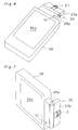
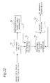
- FIGs. 1, 2, and 3 are a front view, a side view, and a circuit block diagram of the electronics still camera, respectively.
- the electronics still camera 1 comprises a card camera having an image input unit, which is composed of a lens 4 and a CCD (Charge-Coupled Device) 5, provided in the center of a card-like body 3 as shown in Figs. 1 and 2.
- CCD Charge-Coupled Device
- the electronics still camera 1 reproduces still image information written in image-use memory.
- drive pulses are generated by a drive pulse generator 8 based on a timing signal derived from a synchronizing signal generator 7, whereby a drive signal for the CCD 5 is generated by a drive circuit 9.
- an output signal from the CCD 5 is sampled by a sample hold circuit 10, gain-controlled by an AGC (Automatic Gain Control) compressor 11, and thereafter log-compressed.
- the log-compressed signal is converted into a digital signal by an A/D (Analog-to-Digital) converter 12, and then log-expanded by an expander 13. Further, it undergoes such processes as color separation, horizontal/vertical edge correction, ⁇ -correction, and white balance by a processor 14.
- R, G, and B signals obtained in this way are stored via a data buffer 15 into an image memory 16 composed of R memory, G memory, and B memory.
- the R, G, and B signals thus stored in the image memory 16 are transmitted to the reproducing section 2 via the connectors 6. Then, they are converted into analog signals by a D/A (Digital-to-Analog) converter 17 of the reproducing section 2, and amplified by an image amplifier 18. Thus, a still image is displayed on a monitor 19 based on the amplified analog signals.
- Various types of image processing involved in this display process for the picked-up still image are executed by an unshown image processing unit on the reproducing section 2 side.
- an image input unit composed of a lens 4 and a CCD 5 is provided in the center of the card-like body 3, while connectors 6 are provided on a side edge. Therefore, when the electronics still camera 1 is operated to pick up an image under real-time monitoring in connection with the exclusive-use reproducing section 2, the generally entire body 3 except the connectors 6 is projected from the reproducing section 2. This results in a poor convenience of use, as a problem.
- the electronics still camera 1 when it is connected to the reproducing section 2, one-way access only from the electronics still camera 1 side is permitted. Therefore, the image memory 16 cannot be accessed from the reproducing section 2 side. As a result, it is impossible to read necessary image data stored in the image memory 16 from the reproducing section 2 side, execute image processing on them, and transfer the processing results to the electronics still camera 1 once again.
- the lens 4 is projected vertical to a direction in which the card-like body 3 extends.
- the camera 1 is not provided with the function of producing a shutter sound at the press of the shutter switch 20. As a result, the operator cannot be sure that image data of the subject has been captured by an operation of the shutter switch.
- the object of the present invention is therefore to provide a user-friendly card type camera which is capable of executing image processing upon digital image data stored in memory, being connected to an external information processing device, allowing real-time monitoring from the connected information processing device side, and gaining access to the memory from the external information processing device side.
- the card-type camera according to the invention is defined in claim 1.
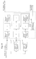
- Fig. 4 is a block diagram of a card type camera of an embodiment.
- This card type camera is made up generally of an image input unit 23 and an IC card unit 33.
- the image input unit 23 is composed of an image forming part 21 comprising an optical lens and the like, and an image pick-up part 22 comprising a CCD, a CCD drive circuit, an A/D converter, and the like.
- the IC card unit 33 comprises a memory 24, a memory controller 25, a hand-move corrector 26, a brightness converter 27, an edge enhancer 28, an edge amount detector 29, an error diffuser 30, an adaptive binarizer 31, and an IC card interface 32, all of which are contained in a card-like body in the form of LSI (Large-Scale Integrated circuit).
- LSI Large-Scale Integrated circuit
- the IC card unit 33 has an IC card connector 34 provided at a side edge thereof and connected to the IC card interface 32. This allows the IC card unit 33 to be connected to an external portable information device or an information processing device such as personal word processors and personal computers.
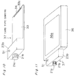
- Fig. 5 is an external view of an example of the card type camera and a portable information device of the electronic notebook type, which is an example of the external information processing device to which the card type camera is fitted.
- the IC card unit 33 of the card type camera 35 is card-like shaped and has an image input unit 23a provided at an end portion thereof.
- the image input unit 23a is arranged to be bendable at a hinge 35a serving as a movable means.
- the angle of the optical axis of a lens 21a forming the image forming part 21 with respect to the surface of the IC card unit 33 is variable.
- the card type camera 35 is fitted to a portable information device 36 by inserting the IC card unit 33 into a slot 36b of the portable information device 36.
- the IC card connector 34 provided at an edge 33a of the other end of the IC card unit 33 is connected to a connector provided inside the portable information device 36.
- an image captured from the image input unit 23a of the card type camera 35 can be displayed on a display screen 36a of the portable information device 36 in real time, or results of image processing, which will be described later, executed upon the image data temporarily stored in the memory 24 (see Fig. 4) can be displayed on the display screen 36a.
- reference numeral 51 denotes a shutter switch and 49 (seeFig. 4) denotes a shutter sound generator for generating a shutter sound.
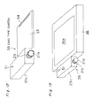
- Fig. 6 is a view in which the card type camera 35 has been fitted to the portable information device 36.
- the image input unit 23a is projected out of the portable information device 36 so that photographing is possible.
- subjects in the forward direction can be photographed by positioning the display screen 36a generally horizontal.
- subjects in the forward direction can be photographed by positioning the display screen 36a vertical, while subjects in the downward direction can be photographed by positioning the display screen 36a horizontal.
- subjects in the backward direction can be photographed by positioning the display screen 36a vertical, while subjects in the upward direction can be photographed by positioning the display screen 36a horizontal.
- Focusing adjustment in the card type camera 35 can be attained by manual adjustment, as shown in Fig. 9, by turning an outer barrel 21b of the image forming part 21.
- a card type camera 37 as shown in Fig. 10 is formed in such a way that the image input unit 23b of the card type camera 35 as shown in Fig. 5 is fixed to the IC card unit 33, so that the card type camera 37 is simplified in construction.
- the direction in which the surface of the display screen 36a extends and the direction of the optical axis of the lens 21a are fixedly set so as to be identical to each other.
- a card type camera 38 as shown in Fig. 12 is a modification of the card type camera 37 as shown in Fig. 10.
- the lens 21a is attached beside an image input unit 23c.
- the lens 21a is directed leftward.
- an image input unit 23d is provided with a movable means so that an end portion is rotatable about the axis of the card type camera 39.
- the lens 21a and its outer barrel 21b are provided on a side face of the rotating part 21c, whereby the image forming part 21 is formed at the rotating part 21c.
- the optical axis of the lens 21a is rotatable through 360 degrees within a horizontal plane.
- a card type camera 40 as shown in Fig. 16 is so arranged that an image input unit 23e and the IC card unit 33 are provided with connectors 23f, 33a or connectors 23g, 33b as the connecting and attaching means, as shown in Fig. 17 or 18, whereby the image input unit 23e is attachable to and removable from the IC card unit 33.
- the image input unit 23e is separated from the IC card unit 33, both are connected to each other via the connectors 23f, 33a or 23g, 33b with a cable 41a or a cable 41b as the image data transfer means.
- the lens 21a of the image input unit 23e can be directed in any direction freely without being restricted by the direction of the display screen 36a of the portable information device 36.
- the image input unit 23e is provided independently of the IC card unit 33 so as not to be removable therefrom, where both are connected to each other with a cable 41.
- the arrangement may be cableless by using a radio transmission means or an optical transmission means as the image data transfer means.
- the card type camera 35, 37, 38, 39, or 40 in the present embodiment when it is fitted to the portable information device 36 with the image input unit 23a, 23b, 23c, 23d, or 23e provided at a side portion of the IC card unit 33 or independently thereof, the entire IC card unit 33 is contained in the portable information device 36 so as to be hidden, where only the image input unit 23 is projected out of the portable information device 36.
- the card type camera is very convenient to use because the generally entire IC card unit 33 is prevented from being projected out of the portable information device 36, which would be involved in the conventional electronics still camera 1 shown in Fig. 1.
- the movable means is used so that the direction of the incident-side optical axis of the image forming part 21 is variable with respect to the direction in which the IC card unit 33 extends, i.e., the direction of the lens 21a is turnable.
- the image input unit 23e is separated from the IC card unit 33.
- Fig. 19 is a block diagram of the portable information device 36.
- a CPU (Central Processing Unit) 42 controls a system controller 44 and a PCMCIA (Pulse Code Modulation Computer Interface Adapter) controller 45 according to a system program stored in a main memory 43 to thereby control the operation of image capture process performed by the card type cameras (hereinafter, typified by the card type camera 35) and operations of various types of image processing later described in detail. Further, by controlling the system controller 44, the PCMCIA controller 45, and a display controller 47, the CPU 42 displays an image onto a liquid crystal display (LCD) as the display screen 36a via a video memory 48 based on image data derived from the card type camera 35 and captured via the connector 46.
- LCD liquid crystal display
- Fig. 20 is a flow chart of the operation of image capture process to be executed on the card type camera 35 side under the control of the CPU 42 in the portable information device 36. The following description on the operation of image capture process goes on according to Fig. 20.
- step S1 such processes are executed as initializing registers of the IC card unit 33, setting functions of image processing to be executed, and setting a region of the memory 24 of which image data is transferred to the portable information device 36.
- the functions of image processing to be executed in this step may be all of the image processing functions, i.e., the hand-move correction process, brightness conversion process, edge enhancement process, edge amount detection process, error diffusion process, and adaptive binarization process, or may be only the error diffusion process or the adaptive binarization process necessary for displaying an image onto the display screen 36a of the portable information device 36.
- the setting may be such that an image optimum for the image display means of the information processing device to which the card type camera is fitted can be displayed.
- step S2 image data corresponding to one field image is grabbed by the image pick-up part 22 for the focusing adjustment, brightness conversion, and other processes, and digitized and stored in the memory 24.
- step S3 the image data of the one field image stored in the memory 24 is read from the region set at step S1, and the image processing set at step S1 out of the above-described image processing functions is executed on the read image data.
- step S4 the image data of the one field image that has undergone the image processing at step S3 is transmitted by the IC card interface 32 to the portable information device 36 via the IC card connector 34. Then, based on the image data transmitted in this way, an image is displayed on the display screen 36a on the portable information device 36 side.
- step S5 it is decided whether or not the shutter switch 51 provided in the card type camera 35 has been pressed, or whether or not a shutter operation has been instructed from the portable information device 36 side.
- the program goes to step S6. Meanwhile, if the shutter switch has not been pressed because a desired image is not displayed on the display screen 36a, the program returns to step S2 to fetch the next one field image.
- one field image will be displayed one after another on the display screen 36a in the portable information device 36 until the shutter is pressed. While this is done, manual focusing adjustment is performed, for example in the above-described manner, by the operator referring to the images displayed one by one on the display screen 36a. Then, if the shutter switch is pressed by the operator with a desired image displayed on the display screen 36a, it is decided at step S5 that the shutter switch has been pressed, where the program moves to step S6.
- step S6 image data of the next field image that succeeds the field image captured at the press of the shutter switch is captured by the image pick-up part 22, and digitized and stored in the memory 24.
- step S7 now that the frame image has been captured in the memory 24, image capture is halted.
- step S8 the image processing set at step S1 is executed on the image data of the frame image stored in the memory 24.
- step S3 is in any case purposed to display a monitoring-oriented image onto the display screen 36a of the portable information device 36
- the present step is designed for primary image processing such as hand-move correction to be executed on the frame image captured by the operator.
- step S9 image data of the frame image that has undergone the image processing at step S8 is transmitted by the IC card interface 32 to the portable information device 36 via the IC card connector 34, where the operation of image capture process is ended.
- the card type camera 35 when fitted to the portable information device 36, functions as if it were one camera unit.
- one field image of a subject is captured and subjected to the error diffusion process, adaptive binarization process, and other processes, and displayed in real time on the display screen 36a of the portable information device 36.
- the shutter switch 51 is pressed with an optimum image obtained, image data of frame images including the above one field image and the next field image is captured and stored in the memory 24. Thereafter, the frame image data is subjected to the previously set image processing, such as the hand-move correction process, and transmitted to the portable information device 36.
- the image to be displayed in real time on the display screen 36a is displayed based on the image data that has undergone the image processing such as the error diffusion process and adaptive binarization process. Therefore, the image display means that displays an image on the display screen 36a, whether an image display means or a liquid crystal display means capable of multi-level halftone display, is enabled to display a high-grade image.
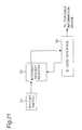
- Fig. 21 is a block diagram for the shutter switch pressing operation.
- the shutter switch 51 provided in the image input unit 23 of the card type camera 35 is pressed, information representing an interrupt request from the shutter switch 51 is written into an interrupt request register 52 while an interrupt signal is transmitted to the IC card interface 32. Then, the interrupt signal is transmitted by the IC card interface 32 to the portable information device 36 via the IC card connector 34.
- the CPU 42 of the portable information device 36 accesses the interrupt request register 52 via the IC card interface 32. Then, when it detects the information representing an interrupt request derived from the shutter switch 51, it confirms that the interrupt is one due to a press of the shutter switch.
- the CPU 42 On the portable information device 36 side, when it receives the interrupt signal derived from the shutter switch 51 or when it has confirmed an interrupt request due to a press of the shutter switch, it is decided whether or not interrupt processing is currently possible. If the interrupt processing is impossible, the CPU 42 displays so on the display screen 36a. On the other hand, if the interrupt processing is possible, the CPU 42 transmits a sound signal to the card type camera 35 side, causing the shutter sound generator 49 to generate a shutter sound. After these processes are completed, the image data capture control for the next frame image is executed.
- interrupt request information derived from the shutter switch 51 and written in the interrupt request register 52 is cleared by access (read or clear request) from the portable information device 36 side.
- the individual processes of image processing are described in detail, including the hand-move correction process to be executed by the hand-move corrector 26 in the IC card unit 33, the brightness conversion process to be executed by the brightness converter 27, the edge enhancement process to be executed by the edge enhancer 28, the edge amount detection process to be executed by the edge amount detector 29, the error diffusion process to be executed by the error diffuser 30, and the adaptive binarization process to be executed by the adaptive binarizer 31.
- shift amount between the two field images is first determined by making use of representative-point matching.
- the shift amount determined is used as an offset value of address for reading image data of either one of the two field images from the memory 24.
- Fig. 22 is a detailed block diagram of the hand-move corrector 26.
- Image data of one field image (e.g., an odd-field image) at a time point captured by the image pick-up part 22 is inputted to a low-pass filter 53. Then, noise components of the image are removed by an IIR (Infinite Impulse Response) low-pass filter using image data of an attentional pixel, a one-line preceding pixel, and a one-pixel preceding pixel out of the image data of the odd-field image.
- IIR Intelligent Impulse Response
- a plurality of representative points are selected out of the odd-field image data that has had noise components removed, and stored in a representative-point table by a representative-point table generator 54.
- image data of an even-field image succeeding the odd-field image is captured and has its noise components removed by the low-pass filter 53 in the same way as above.
- a matching process is executed between the individual pixels of the even-field image data that has had noise components removed, and the representative points.
- the matching process in this case is executed within a specified search range (n pixels ⁇ m pixels) where the pixel corresponding to the representative point is positioned as (1, 1).
- a difference between the brightness value of each representative point in the representative-point table and the brightness value of each pixel within the above search range corresponding to the representative point in the even-field image data is calculated by a difference calculator 55.
- the brightness value of a pixel in the even-field image data in this case is determined by an average value of the brightness values of pixels that are adjacent to each other on succeeding two lines in the pertinent even-field image data. This is because a frame image is composed of an odd-field image and an even-field image, and a line of the even-field image exists between the succeeding two lines of the even-field image.
- a remaining-difference table generator 56 generates a remaining-difference table by adding an absolute value of the difference obtained by the difference calculator 55 to like elements in all the matrices associated with all the representative points. This addition process is executed sequentially, and the contents of the remaining-difference table that are effective upon completion of the processing for the succeeding two field images are taken as the matching result.
- An offset detector 57 searches an element showing a minimum value out of the remaining-difference table generated by the remaining-difference table generator 56. It detects the address of a searched element as the aforementioned offset value equivalent to the shift amount between the odd-field image and the even-field image.
- the offset value detected in this way is transmitted to the memory controller 25, and used as correction data for reading the even-field image data from the memory 24.
- the image data of the frame image can be read out so that there will not occur any shift between the odd-field image and the even-field image.
- an effective hand-move correction process can be achieved.
- a ⁇ -correction process is executed on an output signal from the CCD.
- the brightness value is desired to be changed according to the characteristics of the image display means of the portable information device 36, to which the card type camera 35 is fitted, or where a brighter or darker image is desired to be displayed according to the brightness of the environment.
- brightness conversion is performed by the brightness converter 27 based on the look-up table, while in the latter case the accumulation time of the CCD is controlled in the image capture process.
- the brightness conversion conditions can be controlled from the portable information device 36 side, by the arrangement that information can be transferred bidirectionally by the IC card interface 32.
- Fig. 23 is a detailed block diagram of the brightness converter 27.
- An address selector 58 selects an address of a RAM (Random Access Memory) 59 in correspondence to the brightness value of an input image based on image data read from the memory 24 under the control of the memory controller 25.
- the RAM 59 is accessed based on the selected address so that a new brightness value in the look-up table stored in the RAM 59 is read and transmitted to the edge enhancer 28. That is, in short, the brightness value of an input image is converted into another by using the look-up table.
- the brightness value can be converted into various brightness data by changing the contents of the RAM 59.
- Updating the contents of the RAM 59 in this process is achieved in the following way. That is, in synchronization with write control information inputted from the portable information device 36 side via the IC card interface 32, a RAM controller 60 generates an address signal and transmits it to the address selector 58. Further, the RAM controller 60 generates a write signal and transmits it to the RAM 59. Then, the RAM controller 60 writes a new element value (brightness data) of the look-up table fed from the portable information device 36 to an address of the RAM 59 selected by the address selector 58 based on the aforementioned address signal.
- the above write control information and new element value of the look-up table constitutes update information for the aforementioned conversion table.
- display at a brightness according to the ambient conditions is enabled by allowing the brightness data written into the RAM 59 to be rewritten by an external information processing device.
- the image display means of the information processing device is an image display means that performs halftone expression by controlling the lighting time of pixels, display can be made at an optimum brightness according to the brightness characteristics of the image display means.
- CRTs Cathode-Ray Tubes
- LCDs differ in ⁇ -characteristic from each other, brightness correction according to the ⁇ -characteristic of the image display means used becomes possible.
- the present invention is not limited to this arrangement, but such brightness value conversion may also be carried out on the card type camera 35 side by using a ROM (Read Only Memory) in which brightness data for use of brightness conversion has been written, instead of the RAM 59.
- ROM Read Only Memory
- a clear image can be obtained by executing the edge enhancement process on input image data.
- Such an edge enhancement process is more effective to emphasize the edges of character images.
- Fig. 24 is a detailed block diagram of the edge enhancer 28.
- Image data that has undergone the brightness conversion process by the brightness converter 27 is delayed by a first-in first-out memory 61.
- the delayed image data is further delayed by another first-in first-out memory 62.
- An arithmetic processor 64 converts the brightness value A of the attentional pixel "a” into a new brightness value A' with the use of the brightness values of the above pixels "a” through “e” by the following equation.
- edge enhancement is achieved by enhancing the brightness value of an attentional pixel.
- A' 3A - 1/2(B+C+D+E) where B, C, D, and E are brightness values of the pixels "b", “c", “d”, and “e”, respectively.
- the edge enhancement process is executed selectively only on pixels which are desired to be emphasized. That is, the arithmetic processor 64 decides what extent the brightness values of the neighboring four pixels "b", “c", “d”, and “e” have changed to relative to the brightness value of the attentional pixel "a". For example, for a 256-level halftone input, if one of the values,
- the arithmetic processor 64 executes the brightness conversion upon attentional pixels that have been regarded as needing the edge enhancement process, while it outputs the brightness value, as it is, for attentional pixels regarded as not needing the edge enhancement process.
- varied value "32" of brightness for deciding the need of edge enhancement process may also be set to an optimum value, as required, depending on how the enhancement is made. Besides, it may be made adaptively changeable depending on the brightness of the entire image or the like.
- Such an edge enhancement process if executed on image data captured by the image input unit 23, allows edge portions to be retained in the subsequent error diffusion process as much as possible, or allows fine portions to be kept from being lost in the adaptive binarization process.
- the amount of high-frequency components contained in the image becomes a maximum at a just focusing, naturally. Also, if the number of pixels having a brightness difference of "32" or more from those of neighboring four pixels and therefore needing the edge enhancement process by the arithmetic processor 64 in the edge enhancer 28 (i.e., pixels located at edges) is counted (i.e., the edge amount is detected), the relative amount of high-frequency components contained in the image can be known. Accordingly, it is proper to perform the focusing adjustment in such a way that the edge amount becomes a maximum by using the edge amount as the focusing state.
- the edge amount detector 29 is arranged in the same way as the aforementioned edge enhancer 28. Then, its arithmetic processor counts the number of pixels "a” having a value equal to or more than "32" in any one of the values
- the CPU 42 in the portable information device 36 reads the edge amount via the IC card interface 32, decides the current focusing state in a manner as described below, and displays the decision result onto the display screen 36a.
- the operator can attain the focusing adjustment by referring to the focusing state displayed on the display screen 36a.
- a first focusing-state decision method is to make a decision by the absolute value of edge. That is, while a value representing the edge amount is displayed on the display screen 36a, the operator executes focusing adjustment by referring to the displayed value in such a way that the edge amount becomes a maximum.
- a second focusing-state decision method is to make a decision by the direction of change in the edge amount. That is, with respect to the edge amount obtained from one field image captured at the last time in the loop of step S2 through step S5 in the flow chart of image capture process operation as shown in Fig. 20, a mark representing that the focusing is coming up nearer is displayed on the display screen 36a if the edge amount obtained from the one field image captured this time has increased; a mark representing that the focusing is going away farther is displayed if the edge amount has decreased; and a mark representing that the focusing is a just focus is displayed if the edge amount is generally equal. The operator executes the focusing adjustment so that the mark of just focus will be displayed.
- a third focusing-state decision method is to make a decision by holding a maximum value of edge amounts of images captured in succession in the loop of step S2 through step S5 in the flow chart of the image capture process operation and by comparing the edge amount of the image captured this time with the foregoing maximum value. That is, a mark representing that the focusing is coming up nearer is displayed on the display screen 36a if the comparison between the current edge amount and the maximum value has resulted in an increase; a mark representing that the focusing is going away farther is displayed if the comparison has resulted in a decrease; and a mark representing that the focusing is a just focus is displayed if the comparison has resulted in an equality.
- a fourth focusing-state decision method is to make a decision by normalizing the edge amount. That is, since the edge amount contained in an image varies depending on the brightness or illuminated state of the subject, the edge amount is normalized while the increasing/decreasing rate of edge amount is obtained by dividing an edge amount of an image captured this time by the foregoing maximum value of edge amount. By so doing, a focusing state free from any effect of the absolute value of edge amount can be decided.
- any erroneous decision in making a decision of focusing state can be avoided by passing the edge amount obtained in this way through a proper low-pass filter.
- the edge amount detection process is a function that provides an aid for the focusing adjustment and that enhances the camera's user-friendly convenience. Accordingly, making use of the auxiliary function for focusing adjustment facilitates the operation of focusing adjustment under the viewing of, for example, a poor-contrast LCD 36a.
- the error diffusion process is a process of reflecting any error, which results from replacing a brightness value of one pixel with another brightness value, upon the processing of thresholds for subsequent pixels, when the halftone level of an input image is rounded by using some number of set thresholds, whereby a multi-level halftone display is enabled with a less number of halftone levels by retaining the halftone information of the original image as much as possible.
- Fig. 25 is a detailed block diagram of the error diffuser 30.
- An error adder 65 adds a value of error calculated by an error calculator 69 to the brightness value of an attentional pixel based on image data derived from the edge enhancer 28, thereby giving a brightness value of the pertinent pixel. Then, a threshold processor 66 executes threshold processing upon the new brightness value of the pertinent pixel obtained in this way according to a previously set threshold, and outputs a rounded brightness value to the IC card interface 32.
- An error detector 67 detects an error between the unrounded brightness value derived from the error adder 65 and the rounded brightness value derived from the threshold processor 66. Then, the error detector 67 transmits the value of error detected to the error calculator 69 and a first-in first-out memory 68.
- the error calculator 69 multiplies four error values consisting of an error value related to a pixel one-pixel preceding the attentional pixel and error values related to three neighboring pixels one-line preceding the attentional pixel by their corresponding factors, respectively, based on an error value train derived from the error detector 67 and an error value train derived from the first-in first-out memory 68, and further averages them to determine the error value of the attentional pixel. It is noted that the above four factors are so set that their total becomes less than "1".
- thresholds previously set in the threshold processor 66 and the number of them can be newly set via the IC card interface 32 from the portable information device 36 side.
- Such an arrangement allows the brightness of an input image represented in 8 bits (256-level halftone) to be selectively displayed in 1 bit (2-level) to 4 bits (16-level).
- halftone conversion matching the characteristics of the image display means becomes possible.
- a captured image contains shadows of the card type camera 35 itself, illumination dots, variations in ground intensity and others that the subject originally has, and the like. Therefore, when the image data is binarized with a constant threshold for displaying a black-and-white, two-level image on the display screen 36a, pixels that should properly be displayed black may be dissipated into white, or pixels that should properly be displayed white may be dirtied black.
- the present embodiment is designed to perform an optimum binarization by adaptively changing the threshold value according to the brightness state of images.
- Fig. 26 is a detailed block diagram of the adaptive binarizer 31.
- the threshold processor 75 executes threshold processing by using the threshold derived from the threshold calculator 73 upon the brightness svalue related to the attentional pixel in the image data fed via a first-in first-out memory 74.
- the threshold processor 75 transmits the processing result to the IC card interface 32.
- the threshold for binarizing the brightness value for each attentional pixel is calculated and updated by adding a one-line general brightness variation to a brightness variation of the neighborhood of the attentional pixel. Accordingly, an adaptive binarization process becomes attainable in real time according to the brightness environment of ambient pixels.
- the result of the error diffusion process by the error diffuser 30 and the result of the adaptive binarization process by the adaptive binarizer 31 are transferred by the IC card interface 32 to the information processing device, to which the card type camera is fitted. Then, on the information processing device side, the system controller 44 instructs the PCMCIA controller 45 to adopt and capture via the connector 46 either the result of error diffusion process or the result of adaptive binarization process depending on the display abilities of the display controller 47 and the display screen 36a, under the control of the CPU 42.
- the image data captured in this way and subjected to the error diffusion process or the adaptive binarization process is transferred to the video memory 48 via a system bus, and displayed on the LCD 36a by the display controller 47.
- a threshold to be used by the threshold processor 66 of the error diffuser 30 is set from the portable information device 36 side, and the result of the error diffusion process obtained is adopted so that a halftone image by the four-level halftone display is displayed on the LCD 36a.
- image data in 8 bits (256 levels) per pixel of the captured image can be compressed in the amount of information at a rate of 2 bits (four levels) per pixel, so that 8-pixel image data can be transferred at one time by a 16-bit bus at high speed.
- the display controller 47 and the LCD 36a are capable of only 2-level display, the result of the adaptive binarization process is adopted and a two-level image of high grade subjected to the adaptive binarization process is displayed on the display screen 36a.
- image data for halftone display by low-level halftone and image data for two-level display in correspondence to the ability of the image display means of the information processing device are obtained at high speed by the error diffuser 30 and the adaptive binarizer 31, both integrated into LSI. Accordingly, an image can be displayed in real time on the information processing device side.
- a high-grade image can be displayed whether the image display means of the information processing device, to which the card type camera is fitted, is an image display means capable of halftone display or an image display means capable of displaying only two-level images.
- an image of clear edges subjected to the adaptive binarization process by the adaptive binarizer 31 can be displayed in the case of character images, and natural images subjected to the error diffusion process by the error diffuser 30 can be displayed in the case of natural images.
- one-frame image data captured into the memory 24 is subjected to the image processing such as the hand-move correction process, brightness conversion process, edge enhancement process, edge amount detection process, error diffusion process, and adaptive binarization process, and then transmitted to the portable information device 36 so as to be stored in the main memory 43 or displayed on the display screen 36a.
- the image processing such as the hand-move correction process, brightness conversion process, edge enhancement process, edge amount detection process, error diffusion process, and adaptive binarization process
- unprocessed image data is read by accessing the memory 24 of the card type camera 35 from the portable information device 36 side via the IC card interface 32, and subjected to the above-mentioned image processing by means of software under the control of the CPU 42.
- the processing speed would be lower than in the case where the image processing sections are integrated into an LSI and the aforementioned image processing is executed by means of hardware, as in the present embodiment.
- the portable information device 36 is required to capture images successively at high speed from the card type camera 35 side. Yet, in this process, an image transfer request is issued from the portable information device 36 asynchronously with the cycle at which the card type camera 35 captures images.
- one-sided field e.g., odd field
- even-filed images are simply interpolated vertically between odd-field images to complete image data of a one-frame image.
- the one-frame image is delivered as such to the portable information device 36.
- Figs. 27A, 27B, 27C, 27D, 27E, and 27F are a timing chart in the case where image data of odd-field images captured by the card type camera 35 is read from the card type camera 35 side asynchronously (corresponding to step S4 in the flow chart of image capture process operation as shown in Fig. 20).
- the memory 24 has two RAMs, a first RAM 24a and a second RAM 24b. It is noted that the numbers in the figure are those of field images.
- image data of the first field transmitted from the image pick-up part 22 is written into the first RAM 24a.
- the transfer permit signal for the portable information device 36 goes "H" level.
- the portable information device 36 reads the image data of the first field from the first RAM 24a.
- image data of the third field is transferred from the image pick-up part 22 during the first RAM 24a's operation, the data is written into the second RAM 24b.
- the image data of captured frame images is read by the portable information device 36 at such timing as described below.
- Figs. 28A, 28B, 28C, 28D, 28E, 28F, 28G, 28H, 28I and 28J are a timing chart of reading image data at a press of the shutter switch (corresponding to step S9 in the flow chart of the image capture process operation as shown in Fig. 20).
- image data of odd fields is written into the first RAM 24a and the second RAM 24b in the same manner as in the above-described monitoring state.
- the write address is controlled by the memory controller 25 so that images of both odd and even fields are written into the first RAM 24a and the second RAM 24b.
- image data of successive field images is written into the first RAM 24a and the second RAM 24b.
- Fig. 29 is a block diagram for the generation of a transfer address of the first RAM 24a or the second RAM 24b by the memory controller 25.
- a start address in the X-direction is loaded to a register Xs according to the address data
- an end address in the X-direction is loaded to a register Xe
- a start address in the Y-direction is loaded to a register Ys
- an end address in the Y-direction is loaded to a register Ye.
- the value of the register Xs is first loaded to an X-counter 76 and the value of the register Ys is loaded to a Y-counter 78. Then, the X-counter 76 is incremented (decremented) so that the address is updated. In this process, the address signal from the X-counter 76 is transmitted to the memory 24 and an X-address comparator 77 normally as an x-address signal. On the other hand, the address signal from the Y-counter 78 is transmitted to the memory 24 and a Y-address comparator 79 normally as a y-address signal.
- the X-address comparator 77 compares an address transferred from the X-counter 76 and an end address that has been loaded to the register Xe with each other. When they become equal to each other, the X-address comparator 77 loads the value of the register Xs to the X-counter 76 to increment (decrement) the X-counter 76. Further, it also increments (decrements) the content of the Y-counter 78.
- the Y-address comparator 79 compares an address transferred from the Y-counter 78 and an end address loaded to the register Ye with each other, where when they become equal to each other, it stops the X-counter 76 and the Y-counter 78 from operating.
- an x-address signal outputted from the X-counter 76 and a y-address signal outputted from the Y-counter 78 are used as a CAS (Column Address Strobe signal) and a RAS (Raw Address Strobe signal) for the first RAM 24a or the second RAM 24b, whereby image data can be transferred to the portable information device 36 with the read address automatically updated.
- CAS Cold Address Strobe signal
- RAS Raw Address Strobe signal
- the above start address and end address may be so designated that, for example, image data of a few lines is read every few lines from a field image.
- image data of a small region in the two RAMs is transferred so that high-speed monitoring in real time is enabled.
- the addressing in the memory 24 is effective also for write operation. Accordingly, it is also possible that image data is written into the memory 24 at high speed from the portable information device 36 side with a write area for the memory 24 designated, and after the execution of various types of image processing as described above on the card type camera 35 side, processed image data is returned to the portable information device 36 once again.
- the card type camera has been made up from the image input unit 23, which comprises the image forming part 21 having the optical lens 21a and the image pick-up part 22 having a CCD and the like, and the IC card unit 33, which comprises in the form of an LSI the memory 24, various image processing sections, and the IC card interface 32. Therefore, the card type camera can be combined integrally with the portable information device 36 as if they were one unit camera, by inserting the IC card unit 33 into the slot 36b of the portable information device 36 as an external information processing device.
- the adaptive binarization process by the adaptive binarizer 31 on the image data of an image captured by the image input unit 23 image data for use of halftone display and two-level tone display according to the ability of the image display means of the portable information device 36 can be obtained at high speed, so that the image can be displayed in real time on the display screen 36a of the portable information device 36.
- a high-grade image can be displayed on the display screen 36a without being restricted by the ability of the image display means.
- the card type camera is convenient for the user to use in photographing a subject.
- the edge amount detection process by the edge amount detector 29 by executing the edge amount detection process by the edge amount detector 29 on captured image data, the relative amount of high-frequency components of the image can be detected, whereby the focusing state can be known on the portable information device 36 side. Accordingly, an optimum image can be photographed with focusing adjustment attained by referring to the focusing state in real time.
- the shift amount between two field images constituting one frame image can be detected, whereby any hand move can be corrected by giving an offset value to the read address for image data of either one of the two field images constituting the frame image.
- the frame image can be used as image data of the photographed image, so that the vertical resolution will never deteriorate even with the use of a normal CCD.
- the IC card interface 32 is provided on the card type camera 35 side, the memory 24 or individual information processing sections of the card type camera 35 can be accessed also from the portable information device 36 side. Accordingly, it is possible to set element values of the look-up table to be used in the brightness conversion process, thresholds and the number of them to be used in the error diffusion process, start address and end address for the generation of memory addresses, and the like, from the portable information device 36 side.
- the conversion into image data can be executed and the read/write time to the memory 24 can be shortened.
- the lens 21a constituting the image forming part 21 of the image input unit 23 so as to be rotatable in its direction, or by separating the image input unit 23 from the IC card unit 33, the direction of the subject will never be restricted by the direction of the display screen 36a of the portable information device 36, making the card type camera more convenient to use.
- a shutter sound is generated by the shutter sound generator 49 on the card type camera 35 side in response to a sound signal derived from the portable information device 36. Accordingly, the operator can confirm that image data of the aimed subject has been surely captured.
- the focusing state is decided by the CPU 42 of the portable information device 36 based on the edge amount obtained by the card type camera 35.
- the present invention is not limited to this arrangement, but the focusing state may also be decided on the card type camera 35 side.
- the focusing adjustment has been attained by manual operation. Otherwise, the auto focusing may be applied based on the decision result of focusing state on the information processing device side or the decision result of focusing state on the card type camera side.
- the above embodiment has been so arranged that image data is transferred in the order of the memory 24, the brightness converter 27, the edge enhancer 28, and the error diffuser 30.
- the present invention is not limited to this arrangement, but it is also possible to input image data derived from the memory 24, image data derived from the image pick-up part 22, or image data processed at any image processing section, to the individual image processing sections.
- the above embodiment has been described by taking an example of the portable information device 36 as an external information processing device to which the card type camera is fitted.
- the external information processing device may be a personal word processor, a personal computer, or the like.
- an image picked up with card type camera 35 fitted to the portable information device 36 can be processed by the personal computer or the like.
- the processing operations of the brightness converter 27, the edge enhancer 28, and the edge amount detector 29 have been described by taking a case where an image is displayed on an LCD.
- similar operations are executed to attain "a display by a brightness according to the characteristics of an image display means used," “an enhancement on edge portions,” or “detection of a relative amount of high-frequency components contained in an image.”
Claims (11)
- Caméra de type carte comprenantladite unité de carte à circuits intégrés (33) peut être insérée dans un dispositif de traitement d'information séparé externe (36) par l'intermédiaire d'un emplacement de carte (36b) prévu dans le dispositif de traitement d'information (36), qui réalise un traitement d'image sur les données d'image pour afficher une image capturée à partir de ladite unité d'entrée d'image (23) sur un écran d'affichage (36a) dudit dispositif de traitement d'information (36),une unité d'entrée d'image (23) comportant une partie de formation d'image (21) pour former une image d'un sujet sur une surface de formation d'image et une partie de capture d'image (22) pour capturer l'image sur la surface de formation d'image et produire des données d'image numériques,une unité de carte à circuits intégrés (33) comportant une mémoire (24), et un régisseur de mémoire (25), etun connecteur (34), dans lequel:
caractérisée en ce que
des données d'image provenant de l'unité d'entrée d'image (23) sont mémorisées dans la mémoire (24) et les données d'image mémorisées sont transférées vers le dispositif de traitement d'information (36) connecté électriquement à la caméra de type carte par l'intermédiaire du connecteur (34),
ladite unité de carte à circuits intégrés (33) comprend:ledit moyen de traitement d'image comprend au moins un dispositif de distribution d'erreur (30) pour réaliser une opération de distribution d'erreur sur des données d'image transférées depuis l'unité d'entrée d'image (23) ou sur des données d'image lues dans la mémoire (24), et un numériseur binaire adaptatif (31) pour réaliser une opération de numérisation binaire adaptative dans laquelle un seuil est modifié de manière adaptative en fonction d'une luminosité ambiante pour des données d'image transférées depuis l'unité d'entrée d'image (23) ou pour des données d'image lues dans la mémoire (24).un moyen de traitement d'image pour réaliser un traitement d'image sur des données d'image transférées depuis l'unité d'entrée d'image (23) ou sur des données d'image lues dans la mémoire (24); etune interface (32) connectée au connecteur (34) et à la mémoire (24), au régisseur de mémoire (25), et au moyen de traitement d'image, et servant pour une transmission et une réception de données entre au moins un composant parmi la mémoire (24), le régisseur de mémoire (25) et le moyen de traitement d'image, et le dispositif de traitement d'information (36); et - Caméra de type carte selon la revendication 1, dans laquelle
le moyen de traitement d'image comprend également un convertisseur de luminosité (27) pour réaliser une opération de conversion de luminosité sur les données d'image en se référant à un tableau de conversion. - Caméra de type carte selon la revendication 1 ou 2, dans laquelle
le moyen de traitement d'image comprend également un dispositif d'accentuation des contours (28) pour réaliser une opération d'accentuation des contours à l'aide de laquelle une valeur de luminosité d'un pixel ayant une différence de luminosité supérieure à une différence spécifiée par rapport à la luminosité des pixels voisins est accentuée davantage, en se basant sur les données d'image. - Caméra de type carte selon l'une quelconque des revendications 1 à 3, dans laquelle
le moyen de traitement d'image comprend également un détecteur de valeur de contour (29) pour détecter un nombre de pixels ayant une différence de luminosité supérieure à une différence spécifiée par rapport à la luminosité des pixels voisins en tant que valeur de contour, en se basant sur les données d'image. - Caméra de type carte selon l'une quelconque des revendications 1 à 4, dans laquelle
le moyen de traitement d'image comprend également un correcteur déplacé à la main (26) pour détecter une quantité de déplacement entre deux images de demi-trame constituant une image de trame en tant que valeur de décalage pour une adresse de lecture de l'une ou l'autre des deux images de demi-trame en fonction de données d'image transférées depuis l'unité d'entrée d'image (23), et ensuite transférer la valeur de décalage vers le régisseur de mémoire (25) en tant qu'information d'adresse pour lire l'image de trame dans la mémoire (24). - Caméra de type carte selon la revendication 5, dans laquelle
le correcteur déplacé à la main (26) comprend:un moyen de calcul de différence (55) pour calculer des différences entre des valeurs de luminosité d'une pluralité de pixels représentatifs dans l'une ou l'autre de deux images de demi-trame constituant une image de trame, et des valeurs de luminosité de l'ensemble des pixels dans une zone spécifiée incorporant des pixels de l'autre image de demi-trame correspondant aux pixels représentatifs, chacun en tant que position de référence, en fonction de données d'image transférées depuis l'unité d'entrée d'image (23);un moyen de production de tableau de différence restante (56) pour produire un tableau de différence restante en ajoutant des valeurs absolues des différences relatives aux pixels correspondants dans chaque zone spécifiée pour toutes les zones spécifiées, en fonction de résultats de calcul par le moyen de calcul de différence; etun moyen de détection de décalage (57) pour détecter une valeur de déplacement d'une position de référence d'un élément qui fournit une valeur minimale dans le tableau de différence restante en tant que valeur de décalage pour une adresse de lecture de l'autre image de demi-trame. - Caméra de type carte selon l'une quelconque des revendications 1 à 6, dans laquelle
l'unité d'entrée d'image (23) est prévue à une partie extrême sur un côté opposé à un côté où l'unité de carte à circuits intégrés (33) est insérée dans le dispositif de traitement d'information (36), et l'unité d'entrée d'image (23) dépasse vers l'extérieur du dispositif de traitement d'information (36) lorsque l'unité de carte à circuits intégrés (33) est adaptée sur le dispositif de traitement d'information (36) et est connectée électriquement à celui-ci. - Caméra de type carte selon la revendication 7, dans laquelle
l'unité d'entrée d'image (23) comporte un corps et la partie de formation d'image (21a) couplée au corps par un moyen mobile (35a), et une direction d'un axe optique, du côté d'incidence, de la partie de formation d'image (21a) est modifiable par rapport à une direction dans laquelle se prolonge l'unité de carte à circuits intégrés (33). - Caméra de type carte selon l'une quelconque des revendications 1 à 6, dans laquelle
l'unité d'entrée d'image (23e) est prévue indépendamment de l'unité de carte à circuits intégrés (33), comprenant
un moyen de transfert de données d'image (41) pour transférer des données d'image dérivées de l'unité d'entrée d'image (23e) à l'unité de carte à circuits intégrés (33). - Caméra de type carte selon la revendication 9, dans laquellel'unité d'entrée d'image (23e) et l'unité de carte à circuits intégrés (33) comprennent chacune un moyen de connexion (23f, 23g, 33a, 33b) pour les connecter l'une et l'autre et un moyen de fixation pour les fixer l'une à l'autre de manière démontable, etle moyen de transfert de données d'image (41a) transfère des données d'image dérivées de l'unité d'entrée d'image (23e) séparée de l'unité de carte à circuits intégrés (33) vers l'unité de carte à circuits intégrés (33) par l'intermédiaire du moyen de connexion (23f, 23g, 33a, 33b).
- Caméra de type carte selon l'une quelconque des revendications 1 à 10, comprenant également:dans laquelle l'interface (32) réalise une transmission et une réception de signal entre l'interrupteur d'obturateur (51) et le générateur de signal sonore d'obturateur (49), et le dispositif de traitement d'information.un interrupteur d'obturateur (51) pour délivrer un signal d'interruption lorsqu'il est actionné; etun générateur de signal sonore d'obturateur (49) pour produire un signal sonore d'obturateur lors de la réception d'un signal de son transféré par le dispositif de traitement d'information (36) en fonction du signal d'interruption,
Applications Claiming Priority (6)
| Application Number | Priority Date | Filing Date | Title |
|---|---|---|---|
| JP10369694A JP3203127B2 (ja) | 1994-05-18 | 1994-05-18 | カード型カメラ |
| JP10369694 | 1994-05-18 | ||
| JP103696/94 | 1994-05-18 | ||
| JP11089194A JP3459681B2 (ja) | 1994-05-25 | 1994-05-25 | カード型カメラ |
| JP11089194 | 1994-05-25 | ||
| JP110891/94 | 1994-05-25 |
Publications (3)
| Publication Number | Publication Date |
|---|---|
| EP0683596A2 EP0683596A2 (fr) | 1995-11-22 |
| EP0683596A3 EP0683596A3 (fr) | 1996-04-10 |
| EP0683596B1 true EP0683596B1 (fr) | 2000-08-30 |
Family
ID=26444303
Family Applications (1)
| Application Number | Title | Priority Date | Filing Date |
|---|---|---|---|
| EP95107553A Expired - Lifetime EP0683596B1 (fr) | 1994-05-18 | 1995-05-17 | Caméra du type carte avec fonction de traitement d'image |
Country Status (3)
| Country | Link |
|---|---|
| US (1) | US6118485A (fr) |
| EP (1) | EP0683596B1 (fr) |
| DE (1) | DE69518578T2 (fr) |
Families Citing this family (97)
| Publication number | Priority date | Publication date | Assignee | Title |
|---|---|---|---|---|
| US20020082043A1 (en) * | 1994-05-19 | 2002-06-27 | Kari-Pekka Wilska | Device for personal communications, data collection and data processing, and a circuit card |
| US6292272B1 (en) | 1995-08-03 | 2001-09-18 | Canon Kabushiki Kaisha | Image sensor |
| EP1284449A1 (fr) * | 1996-01-29 | 2003-02-19 | Canon Kabushiki Kaisha | Caméra numérique et ordinateur adapté à ladite caméra |
| US20030156217A1 (en) * | 1996-04-03 | 2003-08-21 | Nikon Corporation | Information input apparatus |
| JPH104530A (ja) * | 1996-06-14 | 1998-01-06 | Nikon Corp | 情報記録装置 |
| US6850279B1 (en) * | 1996-06-18 | 2005-02-01 | Sony Corporation | Optical image recording system, and associated processing system |
| JPH1056586A (ja) * | 1996-08-13 | 1998-02-24 | Nikon Corp | 撮像装置 |
| US6256063B1 (en) | 1996-10-02 | 2001-07-03 | Fuji Photo Film Co., Ltd. | Image signal processing unit and electronic still camera |
| FI104222B1 (fi) * | 1996-10-03 | 1999-11-30 | Nokia Mobile Phones Ltd | Modulaarinen matkaviestinjärjestelmä |
| JPH10171010A (ja) * | 1996-12-10 | 1998-06-26 | Canon Inc | カメラ及びその接続装置並びにカメラシステム |
| JPH10200842A (ja) * | 1997-01-07 | 1998-07-31 | Minolta Co Ltd | デジタルカメラ |
| US6786420B1 (en) | 1997-07-15 | 2004-09-07 | Silverbrook Research Pty. Ltd. | Data distribution mechanism in the form of ink dots on cards |
| JPH114367A (ja) * | 1997-04-16 | 1999-01-06 | Seiko Epson Corp | 高速画像選択方法および高速画像選択機能付デジタルカメラ |
| US6618117B2 (en) | 1997-07-12 | 2003-09-09 | Silverbrook Research Pty Ltd | Image sensing apparatus including a microcontroller |
| US6948794B2 (en) | 1997-07-15 | 2005-09-27 | Silverbrook Reserach Pty Ltd | Printhead re-capping assembly for a print and demand digital camera system |
| US7110024B1 (en) | 1997-07-15 | 2006-09-19 | Silverbrook Research Pty Ltd | Digital camera system having motion deblurring means |
| US6690419B1 (en) | 1997-07-15 | 2004-02-10 | Silverbrook Research Pty Ltd | Utilising eye detection methods for image processing in a digital image camera |
| US6624848B1 (en) | 1997-07-15 | 2003-09-23 | Silverbrook Research Pty Ltd | Cascading image modification using multiple digital cameras incorporating image processing |
| US6879341B1 (en) | 1997-07-15 | 2005-04-12 | Silverbrook Research Pty Ltd | Digital camera system containing a VLIW vector processor |
| US7630006B2 (en) | 1997-10-09 | 2009-12-08 | Fotonation Ireland Limited | Detecting red eye filter and apparatus using meta-data |
| US7042505B1 (en) | 1997-10-09 | 2006-05-09 | Fotonation Ireland Ltd. | Red-eye filter method and apparatus |
| US7738015B2 (en) | 1997-10-09 | 2010-06-15 | Fotonation Vision Limited | Red-eye filter method and apparatus |
| US6700684B1 (en) * | 1998-01-28 | 2004-03-02 | Fujitsu Limited | Image inputting apparatus |
| JP2002514021A (ja) * | 1998-04-30 | 2002-05-14 | シー テクノロジーズ アクチボラゲット | 異なるモードで情報を記録する装置 |
| US6853404B1 (en) | 1998-05-11 | 2005-02-08 | Foveon, Inc. | Electronic view camera for tripod mounting |
| JP4099736B2 (ja) * | 1998-06-30 | 2008-06-11 | ソニー株式会社 | 情報処理装置 |
| JP2000020163A (ja) | 1998-06-30 | 2000-01-21 | Sony Corp | 情報処理装置 |
| JP2967271B1 (ja) * | 1998-07-14 | 1999-10-25 | セイコーインスツルメンツ株式会社 | 撮影後に直ちにプリント可能なデジタルカメラ |
| AUPP702098A0 (en) | 1998-11-09 | 1998-12-03 | Silverbrook Research Pty Ltd | Image creation method and apparatus (ART73) |
| KR20010020678A (ko) * | 1999-03-25 | 2001-03-15 | 윌리엄 비. 켐플러 | 프로그램가능한 실시간 화상 처리 |
| US6778216B1 (en) | 1999-03-25 | 2004-08-17 | Texas Instruments Incorporated | Method and apparatus for digital camera real-time image correction in preview mode |
| US7039221B1 (en) * | 1999-04-09 | 2006-05-02 | Tumey David M | Facial image verification utilizing smart-card with integrated video camera |
| JP2000333066A (ja) * | 1999-05-21 | 2000-11-30 | Fuji Photo Film Co Ltd | ディジタル・スチル・カメラおよびその動作制御方法 |
| AUPQ056099A0 (en) | 1999-05-25 | 1999-06-17 | Silverbrook Research Pty Ltd | A method and apparatus (pprint01) |
| JP2001125662A (ja) * | 1999-08-18 | 2001-05-11 | Fujitsu Ltd | 情報処理装置用の認証情報入力手段付き拡張装置、認証情報入力ユニット及び情報処理装置 |
| US6525932B1 (en) | 1999-08-18 | 2003-02-25 | Fujitsu Limited | Expansion unit and electronic apparatus |
| JP4320091B2 (ja) | 1999-08-31 | 2009-08-26 | 富士通株式会社 | 拡張ユニット及び携帯型情報処理装置 |
| JP2001069390A (ja) * | 1999-08-31 | 2001-03-16 | Fujitsu Ltd | 電子機器に取り付け可能な撮像装置 |
| US20060033831A1 (en) * | 1999-09-14 | 2006-02-16 | Nikon Corporation | Electronic still camera |
| JP2001142760A (ja) | 1999-11-15 | 2001-05-25 | Sony Corp | 半導体記憶装置 |
| JP3750462B2 (ja) | 2000-02-22 | 2006-03-01 | コニカミノルタフォトイメージング株式会社 | デジタルカメラおよび記録媒体 |
| US6811492B1 (en) * | 2000-03-20 | 2004-11-02 | Nintendo Co., Ltd. | Video game machine using digital camera and digital camera accessory for video game machine |
| AU4141000A (en) * | 2000-04-24 | 2001-11-07 | Video Domain Technologies Ltd | Surveillance system with camera |
| US6844941B1 (en) * | 2000-06-23 | 2005-01-18 | Xerox Corporation | Color halftoning using a single successive-filling halftone screen |
| JP3744778B2 (ja) * | 2000-08-28 | 2006-02-15 | セイコーエプソン株式会社 | 画像投写装置、画像処理方法および情報記憶媒体 |
| US7197513B2 (en) * | 2000-12-08 | 2007-03-27 | Aol Llc | Distributed image storage architecture |
| US7779117B2 (en) * | 2002-05-31 | 2010-08-17 | Aol Inc. | Monitoring digital images |
| US6933979B2 (en) * | 2000-12-13 | 2005-08-23 | International Business Machines Corporation | Method and system for range sensing of objects in proximity to a display |
| US6900980B2 (en) * | 2001-05-02 | 2005-05-31 | Palm, Inc. | Synchronization cradle with expansion card slots |
| US20040201745A1 (en) * | 2001-09-28 | 2004-10-14 | Eastman Kodak Company | Camera using a memory card with an integrated electronic imager for digital capture |
| JP2003125256A (ja) * | 2001-10-18 | 2003-04-25 | Fuji Photo Film Co Ltd | 撮像装置及び交換ユニット |
| US6842652B2 (en) * | 2002-02-22 | 2005-01-11 | Concord Camera Corp. | Image capture device |
| JP3937924B2 (ja) * | 2002-05-23 | 2007-06-27 | キヤノン株式会社 | 撮像装置及びその制御方法 |
| KR100486527B1 (ko) * | 2002-08-17 | 2005-05-03 | 엘지전자 주식회사 | 카메라를 구비한 이동통신 단말기에서의 촬영제어 장치 및 방법 |
| US7460170B2 (en) * | 2002-09-23 | 2008-12-02 | Hand Held Products, Inc. | Computer expansion module having image capture and decoding functionality |
| KR100461010B1 (ko) * | 2002-11-18 | 2004-12-09 | 삼성전자주식회사 | 고화질 ccd카메라 및 그 제어방법 |
| US7394493B2 (en) * | 2002-11-18 | 2008-07-01 | Samsung Electronics Co., Ltd. | CCD camera utilizing an IRIS and method for controlling the same |
| US6871409B2 (en) | 2002-12-18 | 2005-03-29 | Snap-On Incorporated | Gradient calculating camera board |
| TW587735U (en) * | 2003-01-21 | 2004-05-11 | Animation Technologies Inc | Image capturing device for electronic device |
| US8254674B2 (en) | 2004-10-28 | 2012-08-28 | DigitalOptics Corporation Europe Limited | Analyzing partial face regions for red-eye detection in acquired digital images |
| US7574016B2 (en) | 2003-06-26 | 2009-08-11 | Fotonation Vision Limited | Digital image processing using face detection information |
| US7792970B2 (en) | 2005-06-17 | 2010-09-07 | Fotonation Vision Limited | Method for establishing a paired connection between media devices |
| US8036458B2 (en) | 2007-11-08 | 2011-10-11 | DigitalOptics Corporation Europe Limited | Detecting redeye defects in digital images |
| US7689009B2 (en) | 2005-11-18 | 2010-03-30 | Fotonation Vision Ltd. | Two stage detection for photographic eye artifacts |
| US7920723B2 (en) | 2005-11-18 | 2011-04-05 | Tessera Technologies Ireland Limited | Two stage detection for photographic eye artifacts |
| US7970182B2 (en) | 2005-11-18 | 2011-06-28 | Tessera Technologies Ireland Limited | Two stage detection for photographic eye artifacts |
| US8170294B2 (en) | 2006-11-10 | 2012-05-01 | DigitalOptics Corporation Europe Limited | Method of detecting redeye in a digital image |
| US8520093B2 (en) | 2003-08-05 | 2013-08-27 | DigitalOptics Corporation Europe Limited | Face tracker and partial face tracker for red-eye filter method and apparatus |
| US9412007B2 (en) | 2003-08-05 | 2016-08-09 | Fotonation Limited | Partial face detector red-eye filter method and apparatus |
| US20050129385A1 (en) * | 2003-09-16 | 2005-06-16 | Jmz Llc | Intelligent portable memory device with display |
| JP4175234B2 (ja) * | 2003-10-07 | 2008-11-05 | セイコーエプソン株式会社 | 表示制御装置、携帯型情報端末及び表示制御方法 |
| US20050136746A1 (en) * | 2003-12-19 | 2005-06-23 | Chii-Moon Liou | Replaceable multiple-functional interface card |
| AU2003292627A1 (en) * | 2003-12-25 | 2005-07-21 | Nokia Corporation | Imaging device having auto focus mechanism |
| TWI255428B (en) * | 2003-12-29 | 2006-05-21 | Pixart Imaging Inc | Method of processing digital images |
| EP1679884B1 (fr) * | 2004-12-28 | 2008-01-23 | Seiko Epson Corporation | Appareil et dispositif portable d'imagerie, et téléphone portable l'utilisant |
| JP2007101886A (ja) * | 2005-10-04 | 2007-04-19 | Fujifilm Corp | 撮影装置 |
| US7599577B2 (en) | 2005-11-18 | 2009-10-06 | Fotonation Vision Limited | Method and apparatus of correcting hybrid flash artifacts in digital images |
| EP1987475A4 (fr) | 2006-02-14 | 2009-04-22 | Fotonation Vision Ltd | Detection et correction automatiques de defauts de flash anti-yeux rouges |
| EP2033142B1 (fr) | 2006-06-12 | 2011-01-26 | Tessera Technologies Ireland Limited | Progrès de l'extension des techniques aam des images en niveaux de gris aux images en couleurs |
| KR100817057B1 (ko) * | 2006-08-30 | 2008-03-26 | 삼성전자주식회사 | 동일한 픽셀 데이터 그룹에 포함되는 픽셀 데이터들을메모리의 동일한 뱅크 어드레스로 매핑하는 매핑 방법 및비디오 시스템 |
| DE102006043010A1 (de) * | 2006-09-13 | 2008-03-27 | Robert Bosch Gmbh | Modulares Kamerasystem |
| US8055067B2 (en) | 2007-01-18 | 2011-11-08 | DigitalOptics Corporation Europe Limited | Color segmentation |
| US7995804B2 (en) | 2007-03-05 | 2011-08-09 | Tessera Technologies Ireland Limited | Red eye false positive filtering using face location and orientation |
| US8503818B2 (en) | 2007-09-25 | 2013-08-06 | DigitalOptics Corporation Europe Limited | Eye defect detection in international standards organization images |
| US20090103756A1 (en) * | 2007-10-22 | 2009-04-23 | Ming-Chun Han | Multi-Media Device |
| GB2453964A (en) * | 2007-10-23 | 2009-04-29 | Salix Technology Co Ltd | Video camera with a pivot portion and an interface with a slot of an electronic device |
| US8212864B2 (en) | 2008-01-30 | 2012-07-03 | DigitalOptics Corporation Europe Limited | Methods and apparatuses for using image acquisition data to detect and correct image defects |
| US8344998B2 (en) * | 2008-02-01 | 2013-01-01 | Wimm Labs, Inc. | Gesture-based power management of a wearable portable electronic device with display |
| US8081254B2 (en) | 2008-08-14 | 2011-12-20 | DigitalOptics Corporation Europe Limited | In-camera based method of detecting defect eye with high accuracy |
| JP5189570B2 (ja) * | 2009-08-19 | 2013-04-24 | 株式会社キーエンス | 画像処理装置及び画像処理方法 |
| US8540379B2 (en) | 2010-10-15 | 2013-09-24 | Panasonic Corporation | Image display device and information processing apparatus including the same |
| JP4730480B1 (ja) * | 2010-10-15 | 2011-07-20 | パナソニック株式会社 | 画像表示装置および情報処理装置 |
| KR101909085B1 (ko) * | 2012-09-28 | 2018-10-18 | 삼성전자주식회사 | 다중 셔터 사운드 재생 방법 및 그 전자 장치 |
| LU92208B1 (en) * | 2013-06-07 | 2014-12-08 | Andrzej Jaroslaw Galuszka | Mobile phone or portable PC with a camera |
| USD797751S1 (en) * | 2016-08-22 | 2017-09-19 | Ypb Group Ltd. | Portable OTG anti-counterfeit scanner |
| JP7441016B2 (ja) | 2019-09-20 | 2024-02-29 | キヤノン株式会社 | 撮像装置、情報処理装置、制御方法及びプログラム |
| TWM597877U (zh) * | 2020-01-17 | 2020-07-01 | 宏碁股份有限公司 | 電子裝置組合 |
Family Cites Families (18)
| Publication number | Priority date | Publication date | Assignee | Title |
|---|---|---|---|---|
| US3777636A (en) * | 1970-06-30 | 1973-12-11 | Minolta Camera Kk | Electronic shutter in camera |
| US3791273A (en) * | 1972-10-10 | 1974-02-12 | Eastman Kodak Co | Indicator light for camera having electronic shutter |
| JPS61154368A (ja) * | 1984-12-27 | 1986-07-14 | Toshiba Corp | テレビカメラ装置 |
| JPH07110065B2 (ja) * | 1987-05-01 | 1995-11-22 | 富士写真フイルム株式会社 | デイジタル電子スチルカメラ |
| JPH01176168A (ja) | 1987-12-29 | 1989-07-12 | Nec Corp | 電子カメラ |
| JPH01183638A (ja) * | 1988-01-18 | 1989-07-21 | Fuji Photo Film Co Ltd | シャッタ音発生機構付電子スチルカメラ |
| DE69026846T2 (de) * | 1989-02-10 | 1997-01-09 | Canon Kk | Bildverarbeitungsvorrichtung |
| US5231501A (en) * | 1989-05-25 | 1993-07-27 | Asahi Kogaku Kogyo Kabushiki Kaisha | Still video apparatus |
| JP3226271B2 (ja) * | 1989-07-27 | 2001-11-05 | オリンパス光学工業株式会社 | ディジタル電子スチルカメラ |
| US5063448A (en) * | 1989-07-31 | 1991-11-05 | Imageware Research And Development Inc. | Apparatus and method for transforming a digitized signal of an image |
| DE3928182A1 (de) * | 1989-08-25 | 1991-02-28 | Goedecke Ag | Verfahren zur herstellung von gabapentin |
| JPH04295886A (ja) * | 1991-03-26 | 1992-10-20 | Seiko Epson Corp | 携帯型画像入出力装置 |
| US5475441A (en) * | 1992-12-10 | 1995-12-12 | Eastman Kodak Company | Electronic camera with memory card interface to a computer |
| JP3548191B2 (ja) * | 1993-03-22 | 2004-07-28 | キヤノン株式会社 | カメラ |
| JP2849301B2 (ja) * | 1993-03-25 | 1999-01-20 | 株式会社日立製作所 | 撮像装置 |
| JP3163872B2 (ja) * | 1993-10-21 | 2001-05-08 | 株式会社日立製作所 | コンピュータ機器ならびに撮像装置 |
| JP3325811B2 (ja) * | 1997-09-12 | 2002-09-17 | 岡山大学長 | 手荒れ・肌荒れの検査薬及び検査方法 |
| JPH1183638A (ja) * | 1997-09-12 | 1999-03-26 | Hitachi Ltd | 加圧流動床ボイラー用温度計 |
-
1995
- 1995-05-17 DE DE69518578T patent/DE69518578T2/de not_active Expired - Lifetime
- 1995-05-17 EP EP95107553A patent/EP0683596B1/fr not_active Expired - Lifetime
-
1997
- 1997-11-24 US US08/976,581 patent/US6118485A/en not_active Expired - Lifetime
Also Published As
| Publication number | Publication date |
|---|---|
| US6118485A (en) | 2000-09-12 |
| EP0683596A2 (fr) | 1995-11-22 |
| DE69518578T2 (de) | 2001-04-26 |
| EP0683596A3 (fr) | 1996-04-10 |
| DE69518578D1 (de) | 2000-10-05 |
Similar Documents
| Publication | Publication Date | Title |
|---|---|---|
| EP0683596B1 (fr) | Caméra du type carte avec fonction de traitement d'image | |
| US8564679B2 (en) | Image processing apparatus, image processing method and program | |
| US8749661B2 (en) | Imaging compositions of multiple images having different image ranges | |
| US8334914B2 (en) | Gradation correcting apparatus, and recording medium storing a program recorded therein | |
| CN109547691B (zh) | 图像拍摄方法和图像拍摄装置 | |
| US7129980B1 (en) | Image capturing apparatus and automatic exposure control correcting method | |
| US7454131B2 (en) | Image sensing apparatus with camera shake correction function | |
| US7414657B2 (en) | Image capture apparatus having display displaying correctly oriented images based on orientation of display, image display method of displaying correctly oriented images, and program | |
| KR20020083368A (ko) | 화질을 개선할 수 있는 디지털 카메라 및 그 화질 개선 방법 | |
| JP2006324976A (ja) | 動画撮像装置及びそのプログラム | |
| JPH08331285A (ja) | 画像入力装置 | |
| CN102223480A (zh) | 图像处理装置及图像处理方法 | |
| JP2003348387A (ja) | 資料提示装置 | |
| JP3956311B2 (ja) | 画像データ変換装置及びカメラ装置 | |
| JP3459681B2 (ja) | カード型カメラ | |
| JPH08331495A (ja) | 撮影機能付き電子アルバムシステム | |
| JP3203127B2 (ja) | カード型カメラ | |
| US8570407B2 (en) | Imaging apparatus, image processing program, image processing apparatus, and image processing method | |
| JP7442989B2 (ja) | 撮像装置、該撮像装置の制御方法、及びプログラム | |
| JP2002190984A (ja) | 撮像装置及び撮像方法 | |
| JP2001313868A (ja) | カード型カメラ | |
| JPH04270571A (ja) | 画面表示装置 | |
| JP3624037B2 (ja) | 画像入力装置および画像処理装置 | |
| JP3033309B2 (ja) | 階調補正装置 | |
| JP2000032331A (ja) | 自動露光制御装置 |
Legal Events
| Date | Code | Title | Description |
|---|---|---|---|
| PUAI | Public reference made under article 153(3) epc to a published international application that has entered the european phase |
Free format text: ORIGINAL CODE: 0009012 |
|
| AK | Designated contracting states |
Kind code of ref document: A2 Designated state(s): DE FR GB |
|
| PUAL | Search report despatched |
Free format text: ORIGINAL CODE: 0009013 |
|
| AK | Designated contracting states |
Kind code of ref document: A3 Designated state(s): DE FR GB |
|
| 17P | Request for examination filed |
Effective date: 19960613 |
|
| 17Q | First examination report despatched |
Effective date: 19980422 |
|
| GRAG | Despatch of communication of intention to grant |
Free format text: ORIGINAL CODE: EPIDOS AGRA |
|
| GRAG | Despatch of communication of intention to grant |
Free format text: ORIGINAL CODE: EPIDOS AGRA |
|
| GRAH | Despatch of communication of intention to grant a patent |
Free format text: ORIGINAL CODE: EPIDOS IGRA |
|
| GRAH | Despatch of communication of intention to grant a patent |
Free format text: ORIGINAL CODE: EPIDOS IGRA |
|
| GRAA | (expected) grant |
Free format text: ORIGINAL CODE: 0009210 |
|
| AK | Designated contracting states |
Kind code of ref document: B1 Designated state(s): DE FR GB |
|
| REF | Corresponds to: |
Ref document number: 69518578 Country of ref document: DE Date of ref document: 20001005 |
|
| ET | Fr: translation filed | ||
| PLBE | No opposition filed within time limit |
Free format text: ORIGINAL CODE: 0009261 |
|
| STAA | Information on the status of an ep patent application or granted ep patent |
Free format text: STATUS: NO OPPOSITION FILED WITHIN TIME LIMIT |
|
| 26N | No opposition filed | ||
| REG | Reference to a national code |
Ref country code: GB Ref legal event code: IF02 |
|
| PGFP | Annual fee paid to national office [announced via postgrant information from national office to epo] |
Ref country code: GB Payment date: 20140514 Year of fee payment: 20 |
|
| PGFP | Annual fee paid to national office [announced via postgrant information from national office to epo] |
Ref country code: FR Payment date: 20140509 Year of fee payment: 20 Ref country code: DE Payment date: 20140515 Year of fee payment: 20 |
|
| REG | Reference to a national code |
Ref country code: DE Ref legal event code: R071 Ref document number: 69518578 Country of ref document: DE |
|
| REG | Reference to a national code |
Ref country code: DE Ref legal event code: R071 Ref document number: 69518578 Country of ref document: DE |
|
| REG | Reference to a national code |
Ref country code: GB Ref legal event code: PE20 Expiry date: 20150516 |
|
| PG25 | Lapsed in a contracting state [announced via postgrant information from national office to epo] |
Ref country code: GB Free format text: LAPSE BECAUSE OF EXPIRATION OF PROTECTION Effective date: 20150516 |