EP0678470B1 - Vorrichtung zum Speichern und zur Ausgabe eines biegeelastischen Stabes - Google Patents
Vorrichtung zum Speichern und zur Ausgabe eines biegeelastischen Stabes Download PDFInfo
- Publication number
- EP0678470B1 EP0678470B1 EP95105252A EP95105252A EP0678470B1 EP 0678470 B1 EP0678470 B1 EP 0678470B1 EP 95105252 A EP95105252 A EP 95105252A EP 95105252 A EP95105252 A EP 95105252A EP 0678470 B1 EP0678470 B1 EP 0678470B1
- Authority
- EP
- European Patent Office
- Prior art keywords
- drum
- housing
- rod
- storage drum
- housing shell
- Prior art date
- Legal status (The legal status is an assumption and is not a legal conclusion. Google has not performed a legal analysis and makes no representation as to the accuracy of the status listed.)
- Expired - Lifetime
Links
- 239000011324 bead Substances 0.000 claims description 8
- 210000002105 tongue Anatomy 0.000 claims 2
- 238000005452 bending Methods 0.000 claims 1
- 238000009434 installation Methods 0.000 claims 1
- 230000002787 reinforcement Effects 0.000 claims 1
- 238000010276 construction Methods 0.000 abstract description 5
- 230000001681 protective effect Effects 0.000 abstract 1
- 210000001331 nose Anatomy 0.000 description 6
- 210000003128 head Anatomy 0.000 description 4
- 238000000034 method Methods 0.000 description 3
- 230000008878 coupling Effects 0.000 description 2
- 238000010168 coupling process Methods 0.000 description 2
- 238000005859 coupling reaction Methods 0.000 description 2
- 230000000694 effects Effects 0.000 description 2
- 230000003014 reinforcing effect Effects 0.000 description 2
- 238000004804 winding Methods 0.000 description 2
- 238000007792 addition Methods 0.000 description 1
- 230000000903 blocking effect Effects 0.000 description 1
- 238000005352 clarification Methods 0.000 description 1
- 238000010586 diagram Methods 0.000 description 1
- 238000006073 displacement reaction Methods 0.000 description 1
- 239000003292 glue Substances 0.000 description 1
- 238000007373 indentation Methods 0.000 description 1
- 238000003780 insertion Methods 0.000 description 1
- 230000037431 insertion Effects 0.000 description 1
- 239000000463 material Substances 0.000 description 1
- 230000000630 rising effect Effects 0.000 description 1
Images




Classifications
-
- B—PERFORMING OPERATIONS; TRANSPORTING
- B65—CONVEYING; PACKING; STORING; HANDLING THIN OR FILAMENTARY MATERIAL
- B65H—HANDLING THIN OR FILAMENTARY MATERIAL, e.g. SHEETS, WEBS, CABLES
- B65H75/00—Storing webs, tapes, or filamentary material, e.g. on reels
- B65H75/02—Cores, formers, supports, or holders for coiled, wound, or folded material, e.g. reels, spindles, bobbins, cop tubes, cans, mandrels or chucks
- B65H75/34—Cores, formers, supports, or holders for coiled, wound, or folded material, e.g. reels, spindles, bobbins, cop tubes, cans, mandrels or chucks specially adapted or mounted for storing and repeatedly paying-out and re-storing lengths of material provided for particular purposes, e.g. anchored hoses, power cables
- B65H75/36—Cores, formers, supports, or holders for coiled, wound, or folded material, e.g. reels, spindles, bobbins, cop tubes, cans, mandrels or chucks specially adapted or mounted for storing and repeatedly paying-out and re-storing lengths of material provided for particular purposes, e.g. anchored hoses, power cables without essentially involving the use of a core or former internal to a stored package of material, e.g. with stored material housed within casing or container, or intermittently engaging a plurality of supports as in sinuous or serpentine fashion
- B65H75/362—Cores, formers, supports, or holders for coiled, wound, or folded material, e.g. reels, spindles, bobbins, cop tubes, cans, mandrels or chucks specially adapted or mounted for storing and repeatedly paying-out and re-storing lengths of material provided for particular purposes, e.g. anchored hoses, power cables without essentially involving the use of a core or former internal to a stored package of material, e.g. with stored material housed within casing or container, or intermittently engaging a plurality of supports as in sinuous or serpentine fashion with stored material housed within a casing or container
- B65H75/364—Cores, formers, supports, or holders for coiled, wound, or folded material, e.g. reels, spindles, bobbins, cop tubes, cans, mandrels or chucks specially adapted or mounted for storing and repeatedly paying-out and re-storing lengths of material provided for particular purposes, e.g. anchored hoses, power cables without essentially involving the use of a core or former internal to a stored package of material, e.g. with stored material housed within casing or container, or intermittently engaging a plurality of supports as in sinuous or serpentine fashion with stored material housed within a casing or container the stored material being coiled
-
- B—PERFORMING OPERATIONS; TRANSPORTING
- B65—CONVEYING; PACKING; STORING; HANDLING THIN OR FILAMENTARY MATERIAL
- B65H—HANDLING THIN OR FILAMENTARY MATERIAL, e.g. SHEETS, WEBS, CABLES
- B65H2701/00—Handled material; Storage means
- B65H2701/30—Handled filamentary material
- B65H2701/37—Tapes
- B65H2701/376—Electrician's fish tapes
Definitions
- the invention relates to a device for storage and to output a flexible rod, the for pulling in cables or other electrical lines in cable protection conduits or conduits, with a Housing and a storage drum rotatably mounted in the housing, wherein the storage drum has an annular shape Gap and the housing have an outlet for the rod.
- a device of the aforementioned type is from the DE 30 31 570 C3 known.
- This device has been in the Practice extremely well proven. It serves to move in of cables or other electrical lines in cable protection tubes or empty pipes. This is not about relevant cable or the electrical line in the device saved, but a resilient strand-like Material, in practice mostly in the form of a cylindrical Staff with inherent tension that Endeavored to keep the rod straight or straight.
- This device has a disc-like storage drum on the inner jacket of which is flexible Apply the rod due to the inherent internal stress.
- the Storage drum is rotatable in an adapted housing stored, with the housing surrounding the drum on all sides, is closed on all sides. So that the flexible Rod pulled out of the device and after The drum can be inserted again an annular gap and the housing one Split opposite opening.
- the procedure is as follows that the flexible rod first into the Cable protection tube is inserted until the front end of the Rod emerges at the other end of the cable protection tube.
- the cable is now connected to the rod end and into the Cable protection tube retracted, while the flexurally elastic Inserted the rod back into the device and is stored therein.
- the insertion of the flexible rod for example in a cable protection tube with a considerable Force is connected because of the frictional forces between the rod and the cable protection tube with increasing Length are getting longer, especially since the cable protection tubes often Bends or because other cables are already in the cable protection tube are laid and accordingly Space conditions are becoming increasingly narrow.
- the invention is therefore based on the object of a device to create that even with the highest demands is easy to use or handle and in which the various rods in length and thickness can be used.
- the housing is cup-shaped on one side open is that the storage drum with the storable therein Rod is easily interchangeably stored in the housing and that the storage drum is provided with a manual drive.
- the main advantage is that the storage drum is directly accessible and when needed simply with the stick stored in it against another Drum can be replaced with another rod. It also makes it possible to carry the drum directly to provide a manual drive, which makes it possible to active rotation of the drum with great thrust and pulling forces to transfer the baton.
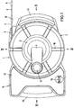
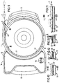
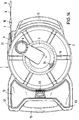
- FIGS 1 to 6 show different views of the Device according to the invention in an operational state.
- Reference number 1 denotes the housing, which bowl-shaped and open on one side upwards is.
- this bowl-shaped housing is one from above Storage drum 2 used so that it is easily accessible and, as will be described in more detail below, with the rod 7 that can be stored therein is easily replaceable in the Housing 1 is mounted.
- the storage drum 2 is with a Provide manual drive, which is essentially a hand crank 4 with a rotatable handle 5.
- the hand crank 4 is in one piece with a slightly conical plate 3 trained, which with reference to Figures 7 and 8 even closer is described.
- a groove-shaped one is open at the top Rod guide 6 provided.
- the rod guide 6 is advantageously in one piece with the bowl-shaped Housing 1 is formed and extends approximately tangentially to the Circumference of the drum 2 to the outside.
- the rod 7 is held on the outside End of a screw 10 for fastening a resilient Intermediate piece 9 is attached, which one elongated guide head 8 carries.
- To the side of the rod guide 6 is an outwardly curved contact bead 11 on the housing shell 1 molded.
- FIG. 1 On the opposite side of the contact bead 11 Side of the housing shell 1 is a receptacle 14 molded for accessories, the one with a cover 12 is provided.
- the lid 12 can be fitted with suitable hinges be attached to the receptacle 14.
- With the reference symbol 13 is an embodiment of a lid lock designated. Is on the outside of the receptacle 14 advantageously a handle 15 integrally formed.
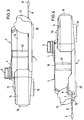
- Figures 1, 3 and 4 show that the storage drum 2 with inward reinforcing beads 16 and 23 can be provided, the reinforcing beads on the Top of the drum 2 radially and on the side walls then run essentially axially parallel.
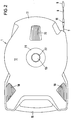
- FIG 2 shows a view of the underside of the housing 1 or the housing shell. It can be seen that the Bottom 17 of the housing shell 1 is essentially flat trained and provided with three support blocks 18, 19 and 20 is. In the bottom 17 there is a conical or frustoconical recess 21 with a circular Opening 50, in which there is a bearing sleeve 22 of the storage drum 2 is located, as shown in Figures 7 and 8 is seen at the upper end with the hand crank 4 of the hand drive connected is.
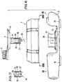
- FIG. 3 shows an exemplary embodiment in a simplified manner a side wall 24 of the housing shell 1.
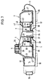
- FIGS. 7 and 8 illustrate the internal design of the device.
- the handle 5 expediently connected to the crank handle 4 by means of a rotary bearing 25 is.
- the hand crank 4 is in turn in one piece on the Molded conically inwardly curved plate 3.
- the dish 3 is non-positive and / or positive with the upper and inner drum wall parts 43 connected.
- a coupling rib 42 on the underside the plate 3 be molded into a corresponding Recess of the relevant neighboring drum wall part intervenes.
- Bearing sleeve 22 points outwards at its lower end protruding annular nose projections 27 which, as in Figure 7 is shown behind the edge of an opening 50 or behind the lower edge of one inserted in the housing shell Grip sleeve 28, which as a guide and pivot bearing for the bearing sleeve 22 is used.
- the attachment of the sleeve 28 the bottom parts of the housing shell 1 can either by Snap or glue in place.
- the said opening 50 and the lower end of the sleeve 28 are in the conical recess 21 of the bottom 17.
- the nose projections 27 are so large and strong and also formally designed so that they too no significant wear after a long period of operation have and the storage drum easily rotatable in the Hold the housing shell.
- the bearing shell 22 advantageously with axially parallel provided slots 26 so that the between located tongue-like parts of the bearing sleeve 22 something can spring elastically.
- FIGs 7 and 8 show other important construction details.
- the housing shell 1 has an inner Housing wall 35, which in the outer area with a upward ring projection 41 is provided.
- This Ring projection 41 engages in an annular gap 46, which between the outer edge of the drum base 32nd on the one hand and the adjacent edge of the outer drum wall 31 is formed.
- the ring projection 41 extends over the entire circumference of the annular gap 46 and seals this so that no rod parts on the circumference unintentionally down through the annular gap 46 can exit. So that the rod 7 at all from the Drum 2 and can also emerge from the housing shell, is the annular projection 41 in the outlet area 49 according to FIG 9 interrupted.
- Figure 11 shows that this interruption of the Ring projection 41 advantageously by flattening is formed in the exit area.
- Figure 11 illustrates furthermore, that this flattening in the exit area 49 the upwardly open groove-shaped rod guide 6 connects.
- Figure 9 also shows that the rod guide 6th tangential to the annular gap 46 and accordingly extends tangentially to the ring projection 41 to the outside.
- the receiving space for the flexible rod 7 in the Storage drum 2 is from an upper drum wall 29, the Drum bottom 32 and an inner substantially cylindrical Drum wall 30 and outer drum wall 31 limited. It is known that the flexible rod 7 can only be subjected to a certain degree of curvature, to avoid deforming it with others Words to achieve that the flexible rod due to the inherent tension after leaving the storage drum always extends straight.
- the rod Due to the tension, the rod is in the saved state striving to curl up on the inner surface of the outer circumference of the storage drum, i.e. on the outside Create drum wall 31.
- the rod When actively winding the Rod by hand drive, the rod at least lays down during the winding process in turns on the inner drum wall 30.
- the inner Drum wall 30 such a large distance from the axis of rotation or have such a large diameter that that in the receiving space located and abutting the drum wall 30 flexible rod 7 no impermissibly large bend experiences.
- it is in the construction the device of advantage that between the inner Drum wall 30 and the bearing sleeve 22 an annular intermediate housing is formed, which is derived from the Drum parts 30, 33, 34 and 43 are composed.
- the inner housing part 33 is designed as a drum sleeve, which for better storage and guidance on one Drum bearing sleeve 37 is seated and is rotatably guided.
- the Drum bearing sleeve 37 is in one piece with a stop ring 38 formed, the same time for attachment with a upper part of a conical bulge 36 of the inner housing wall 35 serves.
- For better centering and Facilitate assembly of the device conical indentation 36 still an inner ring projection 39.
- the inner drum sleeve 33 can still with or be provided with a plurality of slots 44, into which nose projections 45 engage the sleeve 34, which is angular in cross section.
- a further detail is with the reference symbol 48 Mistake. This is a ring stop of the housing bearing 28.
- the inner wall 47 of the housing shell is advantageous cylindrical. Another detail shows the Plate 3, which is provided with a flattened plate rim 40 is.
- the device In the practical Handling the device, it is possible to use the device simply on a suitable support or contact surface create the support blocks 18 to 20, or you can Device also simply with the bead 11 on a wall create and then the device with the handle 15 one hand and the other hand the crank actuate. It is understood that the device in each case keep the flexible rod 7 on the shortest Path into the relevant cable protection tube or empty tube reached.
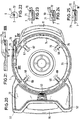
- FIGS 14 to 25 illustrate another embodiment the device according to the invention. So far the individual components with the embodiment according to Figures 1 to 13 match or act the same are the same reference numerals have been used, so that the relevant description of the embodiment according to Figure 1 to 13 also for the embodiment Figures 14 to 25 applies.
- FIG. 14 shows a different cover construction compared to FIG. 1, namely here is the lid 12 on the Top of the receptacle 14 on both sides of the Handle 15 held in pivot bearings 51 and 52.
- Swivel bearings can be used with simple pins 14 used on the outer corners of the cover 12 and are in the holes of the neighboring parts of the Intervene in housing shell 1.
- Lid lock 53 attached in the form of a snap lock.
- a resilient tongue can be used to open the lid operated, for example when closing the lid with a nose projection behind an edge in the Housing shell 1 engages.
- Figure 14 also illustrates some locking ribs 54, which on the top of the inner Drum wall part 43 ( Figure 8) are formed and the in corresponding locking ribs on the underside of the plate 3 intervene and in the assembled state of the device a positive connection between the storage drum 2 and the plate 3 and thus also the hand crank 4 form.
- Figures 15, 18, 19 and 20 illustrate that on Bottom of the storage drum 2 slider 59, 60, 61 and 62 provided are in an external position, as with the Sliders 60, 61 and 62 shown an exit of the in the Storage drum 2 wound rod 7 from the rotating Prevent slot so that in this slide position the storage drum is removed from the housing shell and can be exchanged for another.
- four are advantageous the circumference distributed slider 59, 60, 61 and 62 with radial displacement direction provided.
- the Sliders 59 to 62 in radial slide guides 67, 68, 69 and held 70. If the slide 59 to 62 in the are in the outer position, as in FIG.
- Figures 15 and 16 show a further advantageous embodiment the device according to the invention, namely axially fixed in the bearing sleeve 22, an axis of rotation 64 whose outer end a rotary handle 63 is arranged, which is pivotable between two positions, namely one first position according to Figure 17, in which the with noses 27 provided tabs 65 and 66 of the bearing sleeve 22 are pressed outwards in the operating position, and one second position according to the upper part of Figure 16, in which the tabs 65 and 66 resiliently pivoted inwards are released.
- This is how assembling and disassembling the individual components of the device, especially for replacing the storage drum 2, much easier and in the operating position secure cohesion guaranteed.
- Figures 20 to 25 illustrate another advantageous Design, namely in the rod guide 6th one to the outside, i.e. after the exit end of the rod guide 6 out, rising section 72 is provided, which expediently on the outer wall part 71 and on the bottom of the Rod guide 6 is integrally formed.
- the wall part 71 is materially reinforced so that it is in Operation and not when the device falls can break off.
- the wedge piece has another function, namely, as shown in FIGS. 22 and 23, dimensioned within the rod guide groove 6 so that the rod 7 there is space next to it and at the bottom of the rod guide groove can be moved.
- the wedge piece blocks the further entry, so that the practical handling of the Device is guaranteed that at least the head and usually also a section of the rod outside the rod guide groove 6 remains and is not accidentally wrapped up becomes.
- the blocking position is shown in FIG. 25. that for the said head as well as for one Screw connection 10 takes effect. In practice it can happen that the rod is overstressed on any Spot breaks. Then the entire staff need not be replaced, but you can put both ends on the broken point with a two-sided screw connection 10 connect again. If such Screw connection on the outer front end of the wedge piece 72 hits, the feed lock will take effect first.
Landscapes
- Packaging Of Annular Or Rod-Shaped Articles, Wearing Apparel, Cassettes, Or The Like (AREA)
- Storing, Repeated Paying-Out, And Re-Storing Of Elongated Articles (AREA)
- Storage Of Web-Like Or Filamentary Materials (AREA)
- Vehicle Body Suspensions (AREA)
- Vending Machines For Individual Products (AREA)
- De-Stacking Of Articles (AREA)
Description
Claims (23)
- Vorrichtung zum Speichern und zur Ausgabe eines biegeelastischen Stabes (7), der zum Einziehen von Kabeln oder sonstigen elektrischen Leitungen in Kabelschutzrohre oder Leerrohre dient, mit einem Gehäuse (1) und einer in dem Gehäuse drehbar gelagerten Speichertrommel (2), wobei die Speichertrommel (2) einen kreisringförmigen Spalt (46) und das Gehäuse (1) einen Auslaß für den Stab (7) aufweisen, dadurch gekennzeichnet, daß das Gehäuse (1) schalenförmig einseitig offen ausgebildet ist, daß die Speichertrommel (2) mit dem darin speicherbaren Stab (7) leicht auswechselbar in dem Gehäuse (1) gelagert ist und daß die Speichertrommel (2) mit einem Handantrieb (4, 5) versehen ist.
- Vorrichtung nach Anspruch 1, dadurch gekennzeichnet, daß der Handantrieb eine Handkurbel (4) aufweist, die mit einer Lagerhülse (22) der Speichertrommel (2) verbunden ist.
- Vorrichtung nach Anspruch 2, dadurch gekennzeichnet, daß die Handkurbel (4) einstückig mit einem leicht konisch nach innen gewölbten Teller (3) ausgebildet ist, und daß der Teller kraft- und/oder formschlüssig (42) mit oberen und inneren Trommelwandteilen (43) verbunden ist.
- Vorrichtung nach Anspruch 2 oder 3, dadurch gekennzeichnet, daß die Lagerhülse (22) am Ende nach außen ragende ringförmige Nasenvorsprünge (27) aufweist, die hinter den Rand einer in einer konischen Vertiefung (21) der Bodenfläche (17) der Gehäuseschale (1) vorgesehenen Öffnung (50) greifen.
- Vorrichtung nach einem der Ansprüche 2 bis 4, dadurch gekennzeichnet, daß die Lagerhülse (22) achsparallel verlaufende Schlitze (26) aufweist.
- Vorrichtung nach einem der vorhergehenden Ansprüche, dadurch gekennzeichnet, daß die Gehäuseschale (1) eine innere Gehäusewand (35) aufweist, welche im äußeren Bereich mit einem Ringvorsprung (41) versehen ist, daß der kreisringförmige Spalt (46) zwischen dem äußeren Rand eines Trommelbodens (32) und dem benachbarten Rand der äußeren Trommelwand (31) gebildet ist, und daß der Ringvorsprung (41) auf dem Umfang in den kreisringförmigen Spalt (46) eingreift, jedoch im Austrittsbereich (49) des Stabes (7) aus der Trommel (2) unterbrochen ist.
- Vorrichtung nach Anspruch 6, dadurch gekennzeichnet, daß die Unterbrechung des Ringvorsprunges (41) durch eine Abflachung (49) gebildet ist, an welche sich eine nach oben offene rillenförmige Stabführung (6) anschließt.
- Vorrichtung nach Anspruch 7, dadurch gekennzeichnet, daß die Stabführung (6) einstückig mit der Gehäuseschale (1) ausgebildet ist und tangential zu dem kreisringförmigen Spalt (46) und dem Ringvorsatz (41) nach außen verläuft.
- Vorrichtung nach einem der vorgehenden Ansprüche, dadurch gekennzeichnet, daß der Aufnahmeraum für den biegeelastischen Stab (7) in der Trommel (2) von einer oberen Trommelwand (29), einem Trommelboden (32), einer inneren im wesentlichen zylindrischen Trommelwand (30) und einer äußeren Trommelwand (31) begrenzt ist.
- Vorrichtung nach Anspruch 9, dadurch gekennzeichnet, daß die innere Trommelwand (30) einen so großen Abstand von der Drehachse bzw. einen so großen Durchmesser aufweist, daß der im Aufnahmeraum befindliche und an der Trommelwand (30) anliegende biegeelastische Stab (7) keine unzulässig große Biegung erfährt.
- Vorrichtung nach Anspruch 9 oder 10, dadurch gekennzeichnet, daß zwischen der inneren Trommelwand (30) und der Lagerhülse (22) ein ringförmiges Zwischengehäuse mit Trommelteilen (30, 34, 43) gebildet ist, welches auf einer an der Gehäuseschale (1, 35, 36) angebrachten inneren Trommellagerhülse (37) drehbar geführt ist.
- Vorrichtung nach einem der vorhergehenden Ansprüche, dadurch gekennzeichnet, daß der Boden (17) der Gehäuseschale (1) im wesentlichen ebenflächig ausgebildet und mit drei Auflageklötzen (18, 19, 20) versehen ist.
- Vorrichtung nach einem der Ansprüche 8 bis 12, dadurch gekennzeichnet, daß seitlich der Stabführung (6) ein nach außen gewölbter Anlagewulst (11) an der Gehäuseschale (1) angeformt ist.
- Vorrichtung nach Anspruch 13, dadurch gekennzeichnet, daß auf der dem Anlagewulst (11) gegenüberliegenden Seite der Gehäuseschale (1) ein Aufnahmebehälter (14) für Zubehörteile angeformt ist, der mit einem Deckel (12) versehen ist.
- Vorrichtung nach Anspruch 14, dadurch gekennzeichnet, daß außen an dem Aufnahmebehälter (14) ein Tragegriff (15) angeformt ist.
- Vorrichtung nach einem der vorhergehenden Ansprüche, dadurch gekennzeichnet, daß die Speichertrommel (2) mit nach innen gerichteten Verstärkungssicken (16, 23) versehen ist.
- Vorrichtung nach Anspruch 5, dadurch gekennzeichnet, daß axial in der Lagerhülse (22) eine Drehachse (64) befestigt ist, an deren Ende ein Drehgriff (63) angeordnet ist, welcher zwischen zwei Stellungen schwenkbar ist, einer ersten Stellung, in welcher die mit Nasenvorsprüngen (27) versehenen Laschen (65, 66) der Lagerhülse (22) in Betriebsstellung nach außen gedrückt sind, und einer zweiten Stellung, in welcher die Laschen (65, 66) nach innen federnd schwenkbar freigegeben sind.
- Vorrichtung nach einem der vorhergehenden Ansprüche, dadurch gekennzeichnet, daß am Boden der Speichertrommel (2) Schieber (59, 60, 62, 62) vorgesehen sind, welche in einer äußeren Stellung einen Austritt des Stabes (7) aus der Speichertrommel (2) bei deren Auswechslung verhindern und im Einbauzustand eine Drehbewegung der Speichertrommel (2) in der Gehäuseschale (1) sperren, und welche in einer inneren Stellung die Vorrichtungsbetätigung freigeben.
- Vorrichtung nach Anspruch 18, dadurch gekennzeichnet, daß vier auf dem Umfang verteilte Schieber (59, 60, 61, 62) mit radialer Verschieberichtung vorgesehen sind.
- Vorrichtung nach Anspruch 19, dadurch gekennzeichnet, daß die Schieber (59, 60, 61, 62) in radialen Schieberführungen (67, 68, 69, 70) gehalten sind und durch Öffnungen (55, 56, 57, 58) im Boden (17) der Gehäuseschale (1) betätigbar sind.
- Vorrichtung nach Anspruch 7 oder 8, dadurch gekennzeichnet, daß in der Stabführung (6) ein nach außen ansteigendes Keilstück (72) vorgesehen ist.
- Vorrichtung nach Anspruch 21, dadurch gekennzeichnet, daß das Keilstück (72) an dem äußeren Wandteil (71) und am Boden der Stabführung (6) einstückig angeformt ist.
- Vorrichtung nach den Ansprüchen 14 und 15, dadurch gekennzeichnet, daß der Deckel (12) des Aufnahmebehälters (14) zu beiden Seiten des Tragegriffs (15) in Schwenklagern (51, 52) gehalten ist, und daß im mittleren Bereich des Deckels (12) nahe dem Umfang der Speichertrommel (2) ein Deckelverschluß (53) in Form eines Schnappverschlusses angebracht ist.
Applications Claiming Priority (2)
| Application Number | Priority Date | Filing Date | Title |
|---|---|---|---|
| DE4413247 | 1994-04-16 | ||
| DE4413247A DE4413247C2 (de) | 1994-04-16 | 1994-04-16 | Vorrichtung zum Speichern und zur Ausgabe eines biegeelastischen Stabes |
Publications (3)
| Publication Number | Publication Date |
|---|---|
| EP0678470A2 EP0678470A2 (de) | 1995-10-25 |
| EP0678470A3 EP0678470A3 (de) | 1997-11-19 |
| EP0678470B1 true EP0678470B1 (de) | 1999-09-01 |
Family
ID=6515632
Family Applications (1)
| Application Number | Title | Priority Date | Filing Date |
|---|---|---|---|
| EP95105252A Expired - Lifetime EP0678470B1 (de) | 1994-04-16 | 1995-04-07 | Vorrichtung zum Speichern und zur Ausgabe eines biegeelastischen Stabes |
Country Status (5)
| Country | Link |
|---|---|
| US (1) | US5649674A (de) |
| EP (1) | EP0678470B1 (de) |
| AT (1) | ATE183984T1 (de) |
| DE (2) | DE4413247C2 (de) |
| ES (1) | ES2138675T3 (de) |
Families Citing this family (26)
| Publication number | Priority date | Publication date | Assignee | Title |
|---|---|---|---|---|
| DE19605410C2 (de) * | 1996-02-14 | 1998-05-14 | Katimex Cielker Gmbh | Vorrichtung zum Aufnehmen und Abziehen eines biegeelastischen, strangförmigen Materials |
| US5957399A (en) * | 1997-12-24 | 1999-09-28 | Siana, Jr.; Joseph | Retractor for capturing wire cable |
| DE10104062A1 (de) * | 2001-01-29 | 2002-08-01 | Karl-Heinz Bauer | Einzugskabel |
| US20030079595A1 (en) * | 2001-10-27 | 2003-05-01 | Shahram Shariff | Feed grip for a food slicer |
| GB2388835A (en) * | 2002-05-21 | 2003-11-26 | Electrolux Outdoor Prod Ltd | A cable storage device for a lawnmower |
| GB2410018B (en) * | 2004-01-15 | 2005-12-07 | Nicholas Mitchell | Storage reel |
| TW200950242A (en) * | 2008-05-20 | 2009-12-01 | Ching-Lung Tsai | Cable guide |
| GB0910679D0 (en) * | 2009-06-19 | 2009-08-05 | Numatic Int Ltd | Mobile electrical appliance with cable reeler |
| NO340885B1 (no) * | 2015-12-22 | 2017-07-10 | Loyd Arve Nornes | Oppspolingsapparat for et båndformet element |
| CN210129095U (zh) | 2016-12-15 | 2020-03-06 | 米沃奇电动工具公司 | 管线检查装置 |
| US11251590B2 (en) * | 2017-07-19 | 2022-02-15 | Ecm Industries, Llc | Cable snake |
| CN107565458B (zh) * | 2017-08-29 | 2020-09-01 | 中国建筑第八工程局有限公司 | 手摇式电线管穿线装置及其穿线方法 |
| CN211769548U (zh) | 2018-03-23 | 2020-10-27 | 米沃奇电动工具公司 | 拉线工具以及电动工具 |
| US12322939B2 (en) | 2018-03-23 | 2025-06-03 | Milwaukee Electric Tool Corporation | Fish tape assembly |
| EP4592748A3 (de) | 2018-05-09 | 2025-11-19 | Milwaukee Electric Tool Corporation | Rohrleitungsinspektionsvorrichtung |
| USD988113S1 (en) | 2019-05-09 | 2023-06-06 | Milwaukee Electric Tool Corporation | Receptacle for pipeline inspection device |
| USD983469S1 (en) * | 2019-05-09 | 2023-04-11 | Milwaukee Electric Tool Corporation | Hub for pipeline inspection device |
| EP3966903B1 (de) | 2019-05-10 | 2025-12-17 | Greenlee Tools, Inc. | Kabeleinziehband |
| CN114556728B (zh) | 2019-09-12 | 2024-10-29 | 格林利工具公司 | 穿线器盒 |
| WO2021163241A1 (en) | 2020-02-12 | 2021-08-19 | Milwaukee Electric Tool Corporation | Pipeline inspection device with enhanced image control |
| DE102020106097B3 (de) * | 2020-03-06 | 2021-05-06 | Lübbering Abrollsysteme e. K. Inhaber Achim Lübbering | Kabelführungs- und Verlege-Hilfsvorrichtung |
| CN111573441A (zh) * | 2020-05-25 | 2020-08-25 | 南京博雅达网络科技有限公司 | 一种便于收纳的防尘型网线 |
| WO2022081333A1 (en) | 2020-10-13 | 2022-04-21 | Milwaukee Electric Tool Corporation | Fish tape tool |
| USD1032116S1 (en) * | 2022-07-12 | 2024-06-18 | Lei Zhang | Pipe cleaner |
| US12053081B2 (en) * | 2022-11-30 | 2024-08-06 | Clay Smith | System and method for an adjustable support stake for securing and supporting items above the ground |
| DE102023207550A1 (de) | 2023-08-07 | 2025-02-13 | Robert Bosch Gesellschaft mit beschränkter Haftung | Kabeleinzugsvorrichtung mit einer Lagereinheit zu einer exzentrischen Lagerung eines Zugmittels |
Family Cites Families (18)
| Publication number | Priority date | Publication date | Assignee | Title |
|---|---|---|---|---|
| DE243551C (de) * | ||||
| US1118270A (en) * | 1913-07-17 | 1914-11-24 | Benjamin Dahl | Fish-wire reel. |
| US2300243A (en) * | 1941-06-07 | 1942-10-27 | Frank P Zierden | Hose housing |
| US3415461A (en) * | 1965-10-23 | 1968-12-10 | Cooper Ind Inc | Measuring tape construction |
| US3381916A (en) * | 1966-06-29 | 1968-05-07 | Porter Co Inc H K | Tape rule case and brake construction |
| DE7505287U (de) * | 1975-02-18 | 1975-08-21 | Licentia Patent Verwaltungs Gmbh | Vorrichtung zum Einziehen von Kabeln o. dgl. |
| US4061290A (en) * | 1976-05-13 | 1977-12-06 | Harrill Thomas D | Extension cord reel and case |
| IT7720919U1 (it) * | 1977-03-21 | 1978-09-21 | Zoccoli Stefano | Avvolgitore per prolunghe di cavi elettrici o simili |
| DE2752429A1 (de) * | 1977-11-24 | 1979-05-31 | Popp & Co | Kabeltrommel |
| DE3031570C2 (de) | 1980-08-21 | 1993-01-28 | Werner 5000 Köln Cielker | Vorrichtung zum Aufnehmen und Abziehen eines biegeelastischen strangförmigen Materials |
| GB2126461B (en) * | 1982-09-02 | 1985-10-30 | Ernest Joscelyn Clerk | A hand-held fishing reel |
| IT8321519U1 (it) * | 1983-04-13 | 1984-10-13 | Claber Spa | Avvolgitore portatile per tubo flessibile, particolarmente per autovetture, caravan, pullman, imbarcazioni, terrazzi e piccoli giardini |
| DE3324855A1 (de) * | 1983-07-09 | 1985-01-24 | Rehau Plastiks Ag + Co, 8673 Rehau | Wickeleinrichtung fuer wickelbares gut |
| US4557430A (en) * | 1984-07-19 | 1985-12-10 | Bonhard Robert B | Power cord storage and dispenser |
| US4826100A (en) * | 1988-01-11 | 1989-05-02 | Belliveau Robert C | Device for use in unwinding or rewinding coiled electrical wire |
| US5056731A (en) * | 1990-01-03 | 1991-10-15 | Ideal Industries, Inc. | Fishtape reel and handle |
| ATE137202T1 (de) * | 1992-01-09 | 1996-05-15 | Katimex Cielker Gmbh | Vorrichtung zum speichern von strangförmigem material |
| DE9202150U1 (de) * | 1992-02-19 | 1992-04-16 | Peter Lancier Maschinenbau-Hafenhütte GmbH & Co KG, 4400 Münster | Vorrichtung zum Einziehen von Kabeln in Leerrohre |
-
1994
- 1994-04-16 DE DE4413247A patent/DE4413247C2/de not_active Expired - Fee Related
-
1995
- 1995-04-07 DE DE59506706T patent/DE59506706D1/de not_active Expired - Fee Related
- 1995-04-07 AT AT95105252T patent/ATE183984T1/de not_active IP Right Cessation
- 1995-04-07 EP EP95105252A patent/EP0678470B1/de not_active Expired - Lifetime
- 1995-04-07 ES ES95105252T patent/ES2138675T3/es not_active Expired - Lifetime
- 1995-04-12 US US08/420,811 patent/US5649674A/en not_active Expired - Lifetime
Also Published As
| Publication number | Publication date |
|---|---|
| ATE183984T1 (de) | 1999-09-15 |
| DE4413247C2 (de) | 1996-02-15 |
| DE4413247A1 (de) | 1995-10-26 |
| US5649674A (en) | 1997-07-22 |
| ES2138675T3 (es) | 2000-01-16 |
| DE59506706D1 (de) | 1999-10-07 |
| EP0678470A2 (de) | 1995-10-25 |
| EP0678470A3 (de) | 1997-11-19 |
Similar Documents
| Publication | Publication Date | Title |
|---|---|---|
| EP0678470A2 (de) | Vorrichtung zum Speichern und zur Ausgabe eines biege-elastischen Stabes | |
| DE2913812C2 (de) | Bandkassetten-behaelter zur verwahrung einer bandkassette | |
| DE2517359C2 (de) | Kurbelbetätigtes Bandmaß | |
| DE2434847C3 (de) | ||
| DE3043307C2 (de) | Längenmeßgerät | |
| DE2908342C2 (de) | ||
| DE102016107159B4 (de) | Anschlussvorrichtung | |
| DE2441386B2 (de) | Bandspule | |
| DE2801047A1 (de) | Bandabziehvorrichtung | |
| EP0305738B1 (de) | Dorn zum Aufwickeln von bandförmigem Material | |
| DE2210709C3 (de) | Magnetbandspulenkassette | |
| DE19505926A1 (de) | Kabeltrommel | |
| DD142696A5 (de) | Trommel fuer die aufnahme von bandfoermigem gut | |
| DE2545346A1 (de) | Elektronenroehrenfuss | |
| DE9418157U1 (de) | Kabelschutzelement | |
| DE102019110180A1 (de) | Einzelrohrabdichtung und Kunststoffrohr | |
| DE2548131A1 (de) | Kabelhaspel | |
| EP3327884A1 (de) | Rohreinführung | |
| EP0149072A2 (de) | Tragbare Kabeltrommel | |
| EP2072441A2 (de) | Kabeltrommel | |
| DE3837636A1 (de) | Tastvorrichtung, insbesondere fuer elektrische schalter | |
| DE1950613A1 (de) | Vorrichtung zum Anschliessen eines Geraetes mit geringem Wasserverbrauch an einen Zapfhahn unter Zwischenschaltung einer Schlauchhaspel | |
| DE2850744A1 (de) | Vorrichtung und spule zum auf- und abrollen eines gurtes, z.b. eines sicherheitsgurtes | |
| DE20213994U1 (de) | Verschleißring zur Anbringung an einem Rohr, Schlauch, Kabel o.dgl. und mit dem Verschleißring versehene Wellrohranordnung | |
| DE2736285A1 (de) | Zahnaerztliches handstueck |
Legal Events
| Date | Code | Title | Description |
|---|---|---|---|
| PUAI | Public reference made under article 153(3) epc to a published international application that has entered the european phase |
Free format text: ORIGINAL CODE: 0009012 |
|
| AK | Designated contracting states |
Kind code of ref document: A2 Designated state(s): AT CH DE ES FR GB IT LI PT SE |
|
| PUAL | Search report despatched |
Free format text: ORIGINAL CODE: 0009013 |
|
| AK | Designated contracting states |
Kind code of ref document: A3 Designated state(s): AT CH DE ES FR GB IT LI PT SE |
|
| 17P | Request for examination filed |
Effective date: 19971125 |
|
| GRAG | Despatch of communication of intention to grant |
Free format text: ORIGINAL CODE: EPIDOS AGRA |
|
| 17Q | First examination report despatched |
Effective date: 19980907 |
|
| GRAG | Despatch of communication of intention to grant |
Free format text: ORIGINAL CODE: EPIDOS AGRA |
|
| GRAH | Despatch of communication of intention to grant a patent |
Free format text: ORIGINAL CODE: EPIDOS IGRA |
|
| GRAH | Despatch of communication of intention to grant a patent |
Free format text: ORIGINAL CODE: EPIDOS IGRA |
|
| GRAA | (expected) grant |
Free format text: ORIGINAL CODE: 0009210 |
|
| RAP1 | Party data changed (applicant data changed or rights of an application transferred) |
Owner name: KATIMEX CIELKER GMBH |
|
| RIN1 | Information on inventor provided before grant (corrected) |
Inventor name: CIELKER, WERNER |
|
| AK | Designated contracting states |
Kind code of ref document: B1 Designated state(s): AT CH DE ES FR GB IT LI PT SE |
|
| REF | Corresponds to: |
Ref document number: 183984 Country of ref document: AT Date of ref document: 19990915 Kind code of ref document: T |
|
| REG | Reference to a national code |
Ref country code: CH Ref legal event code: EP |
|
| REF | Corresponds to: |
Ref document number: 59506706 Country of ref document: DE Date of ref document: 19991007 |
|
| ITF | It: translation for a ep patent filed | ||
| ET | Fr: translation filed | ||
| REG | Reference to a national code |
Ref country code: ES Ref legal event code: FG2A Ref document number: 2138675 Country of ref document: ES Kind code of ref document: T3 |
|
| GBT | Gb: translation of ep patent filed (gb section 77(6)(a)/1977) |
Effective date: 20000127 |
|
| REG | Reference to a national code |
Ref country code: PT Ref legal event code: SC4A Free format text: AVAILABILITY OF NATIONAL TRANSLATION Effective date: 19991129 |
|
| PLBE | No opposition filed within time limit |
Free format text: ORIGINAL CODE: 0009261 |
|
| STAA | Information on the status of an ep patent application or granted ep patent |
Free format text: STATUS: NO OPPOSITION FILED WITHIN TIME LIMIT |
|
| 26N | No opposition filed | ||
| REG | Reference to a national code |
Ref country code: GB Ref legal event code: IF02 |
|
| PGFP | Annual fee paid to national office [announced via postgrant information from national office to epo] |
Ref country code: ES Payment date: 20080429 Year of fee payment: 14 Ref country code: DE Payment date: 20080509 Year of fee payment: 14 Ref country code: CH Payment date: 20080415 Year of fee payment: 14 |
|
| PGFP | Annual fee paid to national office [announced via postgrant information from national office to epo] |
Ref country code: AT Payment date: 20080415 Year of fee payment: 14 |
|
| PGFP | Annual fee paid to national office [announced via postgrant information from national office to epo] |
Ref country code: PT Payment date: 20080401 Year of fee payment: 14 Ref country code: IT Payment date: 20080426 Year of fee payment: 14 |
|
| PGFP | Annual fee paid to national office [announced via postgrant information from national office to epo] |
Ref country code: SE Payment date: 20080414 Year of fee payment: 14 |
|
| PGFP | Annual fee paid to national office [announced via postgrant information from national office to epo] |
Ref country code: FR Payment date: 20080412 Year of fee payment: 14 |
|
| PGFP | Annual fee paid to national office [announced via postgrant information from national office to epo] |
Ref country code: GB Payment date: 20080421 Year of fee payment: 14 |
|
| REG | Reference to a national code |
Ref country code: PT Ref legal event code: MM4A Free format text: LAPSE DUE TO NON-PAYMENT OF FEES Effective date: 20091007 |
|
| REG | Reference to a national code |
Ref country code: CH Ref legal event code: PL |
|
| EUG | Se: european patent has lapsed | ||
| GBPC | Gb: european patent ceased through non-payment of renewal fee |
Effective date: 20090407 |
|
| REG | Reference to a national code |
Ref country code: FR Ref legal event code: ST Effective date: 20091231 |
|
| PG25 | Lapsed in a contracting state [announced via postgrant information from national office to epo] |
Ref country code: LI Free format text: LAPSE BECAUSE OF NON-PAYMENT OF DUE FEES Effective date: 20090430 Ref country code: DE Free format text: LAPSE BECAUSE OF NON-PAYMENT OF DUE FEES Effective date: 20091103 Ref country code: CH Free format text: LAPSE BECAUSE OF NON-PAYMENT OF DUE FEES Effective date: 20090430 Ref country code: AT Free format text: LAPSE BECAUSE OF NON-PAYMENT OF DUE FEES Effective date: 20090407 |
|
| PG25 | Lapsed in a contracting state [announced via postgrant information from national office to epo] |
Ref country code: PT Free format text: LAPSE BECAUSE OF NON-PAYMENT OF DUE FEES Effective date: 20091007 |
|
| PG25 | Lapsed in a contracting state [announced via postgrant information from national office to epo] |
Ref country code: GB Free format text: LAPSE BECAUSE OF NON-PAYMENT OF DUE FEES Effective date: 20090407 Ref country code: FR Free format text: LAPSE BECAUSE OF NON-PAYMENT OF DUE FEES Effective date: 20091222 |
|
| REG | Reference to a national code |
Ref country code: ES Ref legal event code: FD2A Effective date: 20090408 |
|
| PG25 | Lapsed in a contracting state [announced via postgrant information from national office to epo] |
Ref country code: ES Free format text: LAPSE BECAUSE OF NON-PAYMENT OF DUE FEES Effective date: 20090408 |
|
| PG25 | Lapsed in a contracting state [announced via postgrant information from national office to epo] |
Ref country code: IT Free format text: LAPSE BECAUSE OF NON-PAYMENT OF DUE FEES Effective date: 20090407 |
|
| PG25 | Lapsed in a contracting state [announced via postgrant information from national office to epo] |
Ref country code: SE Free format text: LAPSE BECAUSE OF NON-PAYMENT OF DUE FEES Effective date: 20090408 |