EP0672824A1 - Mit flüssigem Gas betriebene Brennkraftmaschine - Google Patents
Mit flüssigem Gas betriebene Brennkraftmaschine Download PDFInfo
- Publication number
- EP0672824A1 EP0672824A1 EP95103688A EP95103688A EP0672824A1 EP 0672824 A1 EP0672824 A1 EP 0672824A1 EP 95103688 A EP95103688 A EP 95103688A EP 95103688 A EP95103688 A EP 95103688A EP 0672824 A1 EP0672824 A1 EP 0672824A1
- Authority
- EP
- European Patent Office
- Prior art keywords
- fuel
- throttle valve
- air
- engine
- gas
- Prior art date
- Legal status (The legal status is an assumption and is not a legal conclusion. Google has not performed a legal analysis and makes no representation as to the accuracy of the status listed.)
- Granted
Links
Images


Classifications
-
- F—MECHANICAL ENGINEERING; LIGHTING; HEATING; WEAPONS; BLASTING
- F02—COMBUSTION ENGINES; HOT-GAS OR COMBUSTION-PRODUCT ENGINE PLANTS
- F02B—INTERNAL-COMBUSTION PISTON ENGINES; COMBUSTION ENGINES IN GENERAL
- F02B75/00—Other engines
- F02B75/16—Engines characterised by number of cylinders, e.g. single-cylinder engines
- F02B75/18—Multi-cylinder engines
- F02B75/22—Multi-cylinder engines with cylinders in V, fan, or star arrangement
-
- F—MECHANICAL ENGINEERING; LIGHTING; HEATING; WEAPONS; BLASTING
- F02—COMBUSTION ENGINES; HOT-GAS OR COMBUSTION-PRODUCT ENGINE PLANTS
- F02M—SUPPLYING COMBUSTION ENGINES IN GENERAL WITH COMBUSTIBLE MIXTURES OR CONSTITUENTS THEREOF
- F02M21/00—Apparatus for supplying engines with non-liquid fuels, e.g. gaseous fuels stored in liquid form
- F02M21/02—Apparatus for supplying engines with non-liquid fuels, e.g. gaseous fuels stored in liquid form for gaseous fuels
- F02M21/0218—Details on the gaseous fuel supply system, e.g. tanks, valves, pipes, pumps, rails, injectors or mixers
- F02M21/023—Valves; Pressure or flow regulators in the fuel supply or return system
- F02M21/0239—Pressure or flow regulators therefor
-
- F—MECHANICAL ENGINEERING; LIGHTING; HEATING; WEAPONS; BLASTING
- F02—COMBUSTION ENGINES; HOT-GAS OR COMBUSTION-PRODUCT ENGINE PLANTS
- F02M—SUPPLYING COMBUSTION ENGINES IN GENERAL WITH COMBUSTIBLE MIXTURES OR CONSTITUENTS THEREOF
- F02M21/00—Apparatus for supplying engines with non-liquid fuels, e.g. gaseous fuels stored in liquid form
- F02M21/02—Apparatus for supplying engines with non-liquid fuels, e.g. gaseous fuels stored in liquid form for gaseous fuels
- F02M21/04—Gas-air mixing apparatus
- F02M21/047—Venturi mixer
-
- F—MECHANICAL ENGINEERING; LIGHTING; HEATING; WEAPONS; BLASTING
- F02—COMBUSTION ENGINES; HOT-GAS OR COMBUSTION-PRODUCT ENGINE PLANTS
- F02M—SUPPLYING COMBUSTION ENGINES IN GENERAL WITH COMBUSTIBLE MIXTURES OR CONSTITUENTS THEREOF
- F02M21/00—Apparatus for supplying engines with non-liquid fuels, e.g. gaseous fuels stored in liquid form
- F02M21/02—Apparatus for supplying engines with non-liquid fuels, e.g. gaseous fuels stored in liquid form for gaseous fuels
- F02M21/06—Apparatus for de-liquefying, e.g. by heating
-
- F—MECHANICAL ENGINEERING; LIGHTING; HEATING; WEAPONS; BLASTING
- F02—COMBUSTION ENGINES; HOT-GAS OR COMBUSTION-PRODUCT ENGINE PLANTS
- F02M—SUPPLYING COMBUSTION ENGINES IN GENERAL WITH COMBUSTIBLE MIXTURES OR CONSTITUENTS THEREOF
- F02M7/00—Carburettors with means for influencing, e.g. enriching or keeping constant, fuel/air ratio of charge under varying conditions
- F02M7/12—Other installations, with moving parts, for influencing fuel/air ratio, e.g. having valves
- F02M7/14—Other installations, with moving parts, for influencing fuel/air ratio, e.g. having valves with means for controlling cross-sectional area of fuel spray nozzle
- F02M7/16—Other installations, with moving parts, for influencing fuel/air ratio, e.g. having valves with means for controlling cross-sectional area of fuel spray nozzle operated automatically, e.g. dependent on exhaust-gas analysis
- F02M7/17—Other installations, with moving parts, for influencing fuel/air ratio, e.g. having valves with means for controlling cross-sectional area of fuel spray nozzle operated automatically, e.g. dependent on exhaust-gas analysis by a pneumatically adjustable piston-like element, e.g. constant depression carburettors
-
- F—MECHANICAL ENGINEERING; LIGHTING; HEATING; WEAPONS; BLASTING
- F02—COMBUSTION ENGINES; HOT-GAS OR COMBUSTION-PRODUCT ENGINE PLANTS
- F02B—INTERNAL-COMBUSTION PISTON ENGINES; COMBUSTION ENGINES IN GENERAL
- F02B43/00—Engines characterised by operating on gaseous fuels; Plants including such engines
-
- F—MECHANICAL ENGINEERING; LIGHTING; HEATING; WEAPONS; BLASTING
- F02—COMBUSTION ENGINES; HOT-GAS OR COMBUSTION-PRODUCT ENGINE PLANTS
- F02F—CYLINDERS, PISTONS OR CASINGS, FOR COMBUSTION ENGINES; ARRANGEMENTS OF SEALINGS IN COMBUSTION ENGINES
- F02F7/00—Casings, e.g. crankcases or frames
- F02F7/006—Camshaft or pushrod housings
- F02F2007/0063—Head bolts; Arrangements of cylinder head bolts
-
- F—MECHANICAL ENGINEERING; LIGHTING; HEATING; WEAPONS; BLASTING
- F02—COMBUSTION ENGINES; HOT-GAS OR COMBUSTION-PRODUCT ENGINE PLANTS
- F02M—SUPPLYING COMBUSTION ENGINES IN GENERAL WITH COMBUSTIBLE MIXTURES OR CONSTITUENTS THEREOF
- F02M35/00—Combustion-air cleaners, air intakes, intake silencers, or induction systems specially adapted for, or arranged on, internal-combustion engines
- F02M35/10—Air intakes; Induction systems
- F02M35/104—Intake manifolds
- F02M35/112—Intake manifolds for engines with cylinders all in one line
-
- F—MECHANICAL ENGINEERING; LIGHTING; HEATING; WEAPONS; BLASTING
- F02—COMBUSTION ENGINES; HOT-GAS OR COMBUSTION-PRODUCT ENGINE PLANTS
- F02M—SUPPLYING COMBUSTION ENGINES IN GENERAL WITH COMBUSTIBLE MIXTURES OR CONSTITUENTS THEREOF
- F02M35/00—Combustion-air cleaners, air intakes, intake silencers, or induction systems specially adapted for, or arranged on, internal-combustion engines
- F02M35/10—Air intakes; Induction systems
- F02M35/104—Intake manifolds
- F02M35/116—Intake manifolds for engines with cylinders in V-arrangement or arranged oppositely relative to the main shaft
-
- Y—GENERAL TAGGING OF NEW TECHNOLOGICAL DEVELOPMENTS; GENERAL TAGGING OF CROSS-SECTIONAL TECHNOLOGIES SPANNING OVER SEVERAL SECTIONS OF THE IPC; TECHNICAL SUBJECTS COVERED BY FORMER USPC CROSS-REFERENCE ART COLLECTIONS [XRACs] AND DIGESTS
- Y02—TECHNOLOGIES OR APPLICATIONS FOR MITIGATION OR ADAPTATION AGAINST CLIMATE CHANGE
- Y02T—CLIMATE CHANGE MITIGATION TECHNOLOGIES RELATED TO TRANSPORTATION
- Y02T10/00—Road transport of goods or passengers
- Y02T10/10—Internal combustion engine [ICE] based vehicles
- Y02T10/30—Use of alternative fuels, e.g. biofuels
Definitions
- the present invention relates to a gas-fuelled engine, in particular to a fuel supply device for supplying gaseous fuels such as LPG, LNG or CNG to such a gas-fuelled engine.
- the problem with the above described air/fuel mixture-forming device is that after being in use for a number of years, the air/fuel mixture ratio would tend to deviate from its initial setting. This was caused by carbon and other deposits forming in the fixed venturi and in the main jet opening. The cause is believed to be the formation of oil mists and the subsequent solidification and the carbonation such impurities, which become intermixed by the EGR device or by the blow-by gas return device in the air intake passage and are then blown back into the engine by these intake return systems.
- Another problem with the mixture-forming devices of the prior art is that the unitization of the fixed venturi unit and the throttle valve caused the overall assembly to be bulky, and if it was located in close proximity to the air intake manifold inside the V-bank of a V-type engine, the total height requirement of the engine would be increased. To wit, when the foregoing V-type engine was mounted in an automobile, it was necessary to increase the hood height.
- the present invention provides a gas-fuelled engine as indicated above which improved in that the throttle valve device of a mixture forming system which additionally comprises a variable venturi device is disposed separated from the downstream of the variable venturi device.
- the engine comprises a fuel supply device having a bend area in the air intake member and that the throttle valve is positioned downstream of that bend area.
- variable venturi mixture-forming device being connected with an air intake passage that opens inside a V-bank of a V-type engine with the throttle valve being located within the V bank, and the variable venturi mixer being located outside the V-bank in the axial direction of a crankshaft.
- the present invention makes it possible to position the throttle valve on the engine side at an adequate separation from the venturi unit.
- the arrangement keeps the throttle valve in the vicinity of the engine and prevents the reverse flow of oil mists and other foreign contaminants caused by blow back of intake air in the air intake passage. And further, the high density air/fuel mixture flowing from the venturi area toward the throttle valve holds these contaminants almost entirely in check by means the comparatively high air intake flow.
- said bend area results in the relatively heavy contaminates moving backward through the air intake passage to collide with the inner wall of the bend area of the air intake member, thereby preventing their further reverse flow.
- the other preferred embodiment of this invention places the relatively small throttle valve inside the V-bank but moves the relatively large variable venturi mixer outside the V-bank to reduce engine height requirements.
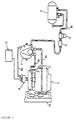
- Figure 1 is an assembly diagram of an embodiment of the fuel supply device for gas-fueled engines of this invention
- Figure 2 is a vertical sectional view of an embodiment of the fuel supply device for gas-fueled engines of this invention
- Figure 3 is a graph of the relationship between air intake flow and fuel flow
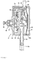
- Figure 4 is an enlarged sectional view of the fuel vaporization device. This embodiment will be explained in terms of a fuel supply device for gas-fueled engines used in automobiles.
- 1 is a gas-fueled engine
- 2 is a storage tank for holding the gaseous fuel.
- the gas in fuel tank 2 is stored under pressure in liquid form, and the fuel line 2a has been designed to transmit the fuel in a liquid form.
- the above mentioned gaseous fuel could be butane, propane, a mixture of them, or any other gaseous fuel substance known to the art.
- the upstream end of the foregoing fuel line 2a is connected to fuel tank 2 while the other end is connected, through a filter 4 and solenoid valve 5, to the fuel inlet of a pressure regulator 3 that will be described below.
- the aforementioned pressure regulator 3 heats the LPG gaseous fuel used in this embodiment to vaporize it from its liquid state, thereby also functioning as a fuel vaporization device.
- This pressure regulator 3 is also connected with a mixture-forming device 6, described below, by means of fuel line 2b.
- 3b is a coolant supply pipe which transmits engine coolant to the pressure regulator 3.
- 2b is a return line for the engine coolant from the pressure regulator 3 back to the engine 1.
- This fuel supply device transmits liquid fuel from the fuel tank 2 to a pressure regulator 3 which vaporizes it into a gas at approximately atmospheric pressure. The gaseous fuel is then mixed with air by the mixture-forming device 6 and supplied to the engine 1.
- reference number 7 indicates an engine control unit (ECU) that controls this fuel supply device.
- ECU 7 controls the operation of such devices as a control valve mechanism, to be described later, that is a part of the mixture-forming device 6, and the ignition system of the engine 1.
- the above mentioned gas-fueled engine 1 is a water-cooled 4-cylinder, 4-valve type engine.
- the cylinder block 10 is mounted atop the crankcase 2, and the cylinder head 11 is fastened on top of the cylinder block 10 by means of head bolts (not shown).
- a head cover 12 is further attached atop the cylinder head 11.
- Pistons 13 have been slidably inserted into the cylinder bores 10a formed in the foregoing cylinder block 10. These pistons 13 are joined to the crankshaft (not shown) by connecting rods.
- Concave combustion areas have been formed on the bottom of the foregoing cylinder head 11, and these, together with the cylinder bores 10a and the tops of the pistons, form the combustion chambers. Two air intake valve openings and two exhaust valve openings are also formed in each of the foregoing concave combustion areas.
- Air intake valves 14, and exhaust valves have been installed in the respective air intake valve openings and exhaust valve openings to open and close those openings.
- These air intake valves 14 and exhaust valves also have respective air intake lifters 15, and exhaust lifters (not shown) affixed to their top ends, and these are located parallel to each other in the direction perpendicular to the cylindrical axis.
- sparkplugs are installed in the foregoing cylinder head 11 so that their electrodes are positioned in the center of the foregoing concave combustion areas.
- a cleaning jacket 17 through which engine coolant is circulated by a coolant pump (not shown) is present inside the foregoing cylinder block 10 and cylinder head 11.
- a coolant temperature sensor 18 also projects into this cleaning jacket 17 in the cylinder block 10.
- This coolant temperature sensor 18 is connected to the foregoing ECU 7 by wires (not shown) to transmit the coolant-temperature output.
- This engine coolant is cooled by circulating it through an external heat exchanger 1a ( Figure 1). It is also possible to attach the foregoing coolant temperature sensor in the area of the thermostat (not shown) that is located near the heat exchanger 1a.
- An air intake passage 19 is present in the side wall 11a of the cylinder 11 which passes air to the combustion chamber through the air intake valve openings.
- An exhaust passage is present on the opposite side of the head from this side wall 11a and connects with the combustion chamber through the exhaust valve opening.
- the wall surface subtending the opening of the foregoing air intake passage 19 is connected to one end of the air intake manifold 20, while the wall surface subtending the opening of the foregoing exhaust passage is connected to one end of the exhaust manifold.
- a plenum chamber 21 is located at the other end of the foregoing air intake manifold 20. Also the other end of the foregoing exhaust manifold is connected to a catalytic converter with a catalyst layer.
- This catalytic layer includes a so-called three-element catalyst which reduces oxides of nitrogen and oxidizes carbon monoxide and hydrocarbons. Exhaust gases that have been treated by the catalytic converter are then expelled through the exhaust and muffler system into the atmosphere.
- An O2 sensor that detects the concentration of oxygen in the exhaust gas is also mounted in the exhaust manifold.
- This O2 sensor may be such as to emit a signal when the air/fuel mixture ratio (A/F) is too rich, or a signal when the A/F is too lean, or a signal when there is a transition from rich to lean.
- A/F air/fuel mixture ratio
- the mixture-forming device 6 is located at the side of the gas-fueled engine 1 and connected to the upstream end of the foregoing air intake manifold 20; it creates the air/fuel mixture that is supplied to the combustion chambers. It is composed of a variable venturi of mixer 22 and a separate throttle valve device 23. This throttle valve device 23 is attached to the air intake manifold 20.
- the lower opening of the foregoing mixer 22 includes a main unit 24 which is connected to the foregoing throttle valve device 23.
- An air intake passage 25 is present at the top of this main unit 24, and this air intake passages is connected to the air cleaner 26. This arrangement allows supplying air from the atmosphere to the air intake passage 25 by introducing it through the air introduction opening 26a of the air cleaner 26 and then passing it through the filter element 26b.
- the above mentioned mixer 22 is equipped with a piston 28 that is slidably mounted in a chamber 27 so that said piston 28 projects into the foregoing air intake passage 25.
- the chamber 27 houses a coil spring 29 which exerts a force upon the piston 28 to close air intake passage 25.
- a metering rod (needle valve) 32 which operates in concert with the main jet 31 of pressure chamber 30 that is connected to the pressure regulator 3 is installed in the front end of the piston 28.
- the main jet 31 and needle valve 32 are shaped so that no matter what the air intake flow volume, they maintain an approximately constant A/F mixture, while maintaining the average aperture of the below-described bleed air control valve 33 at an approximately constant value.
- a bleed port 34 is formed in the front end of piston 26 which passes inside and outside of chamber 27.
- the top part of chamber 27 comprises an atmospheric air port 35 which opens upstream from where the above mentioned main jet 31 opens into the venturi area.
- the atmospheric air port 35 is designed so that the pressure of the atmospheric air on piston 28 causes it to open the air intake passage 25. It would also be possible to design this atmospheric air port to make it pass through chamber 27 and open on the atmospheric air side.
- the foregoing throttle valve device 23 consists of a butterfly throttle valve 36 which opens and closes in the air intake pipe member 23a due to the operation of the throttle. At its upstream end, it is connected to the mixer 22, while the throttle valve 36 is located in the downstream area of the air intake member 23a and is separated from the foregoing throat area by an adequate distance.
- an idle bypass passage 37 is present in the foregoing mixer and detours around the above mentioned throttle valve 36.
- An idle speed control valve 38 is mounted in the idle bypass passage 37 in order to control the idle speed (RPM) of the engine 1.
- the above mentioned idle bypass passage 37 connects with the downstream end of mixer 22 and with the downstream side of throttle valve 36 in a manner such that mixed air fuel formed in the above mentioned throat area bypasses the throttle valve 36 and flows into the engine from the side.
- the idle speed control valve 38 is an electrical control valve, the cross section of the idle bypass passage 37 can be increased or decreased based upon control signals from the ECU 7, thereby controlling the flow of the air/fuel mixture through the idle bypass passage 37 to control the idle speed.
- the upstream-side opening of the idle bypass passage 37 is formed on the same surface as the air intake passage-side opening for the above mentioned main jet 31, so that a richer than normal mixture flows when the idle speed control valve 38 is open.
- the idle speed control valve 38 is located in close proximity to the mixer 22.
- the engine When, in the above described configuration of the idle bypass passage 37, the engine is operating at lower or mid-range operating ranges in which a comparatively small amount of air/fuel volume is required, it is possible to perform feedback control on the air/fuel mixture by utilizing the signal from the O2 sensor. This feature prevents overshoot in the air/fuel mixture control by speedily introducing the outflow from the main jet 31 into the combustion chamber to avoid delay in the feedback response.
- Reference number 38 represents the intake air pressure sensor that is connected to the throttle valve device 23.
- This intake air pressure sensor 38 is designed to detect the pressure in the air intake passage 25 and to emit a signal to the ECU 7.
- the pressure value for the intake air that is detected by this intake air pressure sensor 38 is used to control the ignition timing of the gas-fueled engine 1.
- the above described gas-fueled engine 1 is equipped with an EGR device 41 that reduces No x emissions in the exhaust gases.
- This EGR device 41 is composed of an EGR valve 42 and an EGR regulator 43.
- the EGR valve 42 controls the volume of exhaust gas that returns to plenum chamber 21 of the air intake manifold by means of the first EGR line 44 and the second EGR line 45.
- the structure of the bleed air control valve is such that the degree to which the valve element 33 projects is controlled by a stepping motor; the valve element 33a controls the cross-sectional area of the bleed air passage 46 which opens on the downstream side of the constriction 30a of the fuel supply chamber 30 formed in the mixture-forming device 6.
- the ECU 7 controls the above mentioned stepping motor based upon the output signals from the O2 sensor attached to the exhaust manifold using a feedback control system to drive the stepping motor.
- the upstream end of the foregoing bleed air passage 46 connects to the inside of the air cleaner 26 downstream of the filter element 26b.
- the negative pressure of the air intake passage acts upon the fuel supply chamber 30 to draw gaseous fuel into the fuel supply chamber 30 from the pressure regulator 3 through the constricted area 30a; in addition, air is drawn through the bleed air passage 46.
- this air will be termed "bleed air" in order to distinguish the air that is drawn in from the fuel supply chamber from the air drawn into the throat area from the air cleaner.
- This gaseous fuel and the bleed air are then mixed in the fuel supply chamber 30, and subsequently this mixture passes through the main jet 31 and is drawn into the air intake passage 25. Supposing that the negative venturi pressure that acts upon this fuel supply chamber 30 is constant (and similarly that the air intake volume is roughly constant), then it is possible to control the flow volume of gaseous fuel that is drawn into the fuel supply chamber by changing the bleed air flow volume by adjusting the aperture of the bleed air control valve 33.
- the mixture-forming device 6 controls the flow volume of gaseous fuel supplied to the air intake passage 25 by adjusting the aperture of the above described bleed air control valve 33.
- the bleed air control valve 33 controls the air/fuel ratio.
- the aperture of this bleed air control valve is adjusted by increasing or decreasing the number of steps to the stepping motor that drives it. In this embodiment, when the bleed air control valve is fully closed (aperture 0%) the step number is 0, and when fully open (aperture 100%) the step number is 100.
- a bleed air flow volume regulator valve providing the fine adjustment for the total bleed air volume is located near the bleed air control valve 33.
- This bleed-air flow-volume adjustment valve 47 has an adjustment screw located in the valve body at the front end, and it is held by a spring exerting force against it.
- the structure is such that it can increase or decrease the cross section of the passage that joins the air intake passage 25 with the fuel supply chamber 30.
- ⁇ F/Fc .
- F represents the actual air/fuel ratio
- the units for the amount of air intake are mass flow, but those for the fuel are flow by volume in order to clarify the difference between propane and butane.
- those data curves in the figure that are bent slightly indicate experimental results; they show the relationship between the air intake flow 10 and the fuel flow when various apertures were maintained for the bleed air control valve using 100% propane. All the percentages refer to the % of aperture opening; aperture 0% (step 0) is completely closed, and aperture 100% (step 100) is completely open. The other aperture percentages show additional aperture values lying within that range.
- step 50 which shows the results for 100% propane fuel, approximately overlaps the solid line for the stoichiometric state, meaning that if the step number is held at 50, a stoichiometric state may be maintained even when the air intake flow volume is changed.
- the O2 sensor emits a signal to ECU 7 indicating the air fuel mixture state (lean, stoichiometric, or rich).
- ECU 7 makes a determination of whether or not the signal output by the O2 signal is a rich signal. If the determination is made that it is the rich signal, it causes the stepping motor to be driven at the required speed to open the aperture of the valve element 33a of the bleed air control valve 33. At this time, the step number of the stepping motor would be increased from 50 to 55, for example. With the increase of the step number, the amount of bleed air in the fuel supply chamber 30 increases, causing the amount of fuel to decrease by that same amount. As a result, the air/fuel ratio changes from being in a rich state to a leaner state.
- the ECU 7 when it is determined that the O2 sensor is emitting a lean signal, the ECU 7 operates in a manner opposite from that described above and causes the bleed air valve 33 to be driven toward the closed side, for example, from step 50 to step 45. This reduces the bleed air volume inside the fuel supply chamber 30 in response to the reduced step number, thereby increasing the amount of fuel flow by that same amount. As a result, the air/fuel ratio moves from a lean or stoichiometric state to the rich side.
- the flow volume of the bleed air introduced into the foregoing fuel supply chamber is very small by comparison with the air intake flow, and accordingly the bleed air volume makes no direct contribution to the A/F ratio. Also, because the flow of fuel is controlled by the supply of bleed air, there is no need to make corrections for the fuel flow due to operations at high altitudes. The reason is that both the bleed air and the fuel are gases, therefore their respective densities are affected in a similar manner.
- the pressure regulator 3 that supplies fuel to the foregoing mixture-forming device 6 is configured as shown in Figure 4.
- reference number 51 denotes the housing which forms the main body of the pressure regulator 3.
- the above mentioned fuel line 2a is connected to this housing 51 at the inlet tube 52, and in addition, this inlet tube 52 is linked with an inlet passage 53.
- the inlet passage 53 extends to the first pressure regulation port 54, and this first pressure regulation port 54 is opened and closed by the first pressure regulation valve 55.
- the foregoing first pressure regulation valve 55 is operated by means of the first force-exerting member 58, which is comprised of an adjustment screw 56, spring 57, etc.
- a first cover plate 59 is also attached to the foregoing first housing 51, and this configuration creates a first pressure regulating chamber 60 inside the housing 51.
- the gage pressure of the first pressure regulation chamber 60 can be set to about 0.3 kg/cm2 to adjust the foregoing first force adjustment member 58.
- a diaphragm 61 and a second cover plate 62 are attached on the side of the foregoing housing 51 opposite the first cover 59. These components form the second pressure regulation chamber 63.
- This second pressure regulation chamber 63 is linked to the foregoing first pressure adjustment chamber 60 through a linking passage 64.
- a second pressure regulating valve 65 which can be opened and closed, is mounted in the opening of this linking passage 64 on the second pressure regulation chamber side. The operation of this second pressure regulating valve 65 is performed by means of a second force-exerting member 66 which links it to the movement of the above mentioned diaphragm 61. Atmospheric pressure operates on the back side of diaphragm by means of an atmospheric port 62a.
- the fuel pressure inside the above mentioned second pressure regulating chamber 63 is slightly lower than atmospheric pressure.
- the fuel passes through the fuel supply passage 67, then passes through the fuel line 2b that is connected to the fuel supply passage 65 and finally, it moves on to the fuel supply chamber 30 of the foregoing mixture-forming device 6.
- a heating passage 68 has also is present within the forgoing housing 51.
- This heating passage 68 is positioned adjacent to the foregoing inlet passage 53, and it circulates water heated in the cleaning jacket 24 of engine 1, as shown in Figure 1, through the coolant supply line 3a and the coolant return line 3b.
- the heat from the engine coolant is transmitted to the introduction line in the housing 51.
- Fuel, which flows into the inlet passage 53 in a liquid state is almost entirely vaporized when it flows from the first pressure regulation port 54 to the first pressure regulation chamber 60.
- this pressure regulator 3 makes use of the heat of the engine coolant to vaporize the liquid fuel which compensates for latent heat and raises the temperature of the fuel itself.
- the above mentioned ECU contains a central processing unit (CPU, not shown) and it controls the ignition timing and fuel control by means of the mixture-forming device 8 based upon detection of engine RPM by a sensor (not shown), upon the position of the throttle for throttle valve 36, the exhaust gas temperature, the engine coolant temperature that is detected by the coolant temperature sensor 25, and the concentration of O2 gas in the exhaust gases that is detected by the O2 sensor.
- CPU central processing unit
- the fuel supply device configured as described above vaporizes the fuel from fuel tank 2 in the pressure regulator 3, and then the gaseous fuel is mixed at the set air/fuel ratio in the mixture-forming device 6, whereupon it is supplied, mixed with air, to the engine 1. Also, since the mixture-forming device 6 is composed of a separate mixer 22 and throttle valve device 23, it becomes possible to position the throttle valve 36 an adequate distance away from the venturi unit, at the side of engine 1.
- This design prevents such contaminants from attaching to the main jet 31 or to the venturi of the mixture-forming device 6, thereby enabling it to maintain its initial properties over a long period of time.
- Figure 5 shows a top sectional view of another embodiment in which the piston axis and the intake pipe member lie within the same horizontal plane.
- Figure 6 shows a top sectional view of another embodiment wherein the central axis of the air intake pipe member lies in a horizontal plane and which is perpendicular to the vertical axial line of the piston.
- Figure 7 is a perspective view sighted along arrow VII of Figure 8
- Figure 8 is a top sectional view showing another embodiment wherein the axial line of the piston and the center line of the air intake pipe member run through the same vertical plane.
- Figure 9 is a perspective view sighted along arrow IX of Figure 8.
- the component parts shown in these figures that correspond to those in Figures 1 through 4 bear the same reference numbers, and detailed explanation of these will be avoided.
- the air intake pipe member 23a for the throttle valve devices 23 shown in Figures 5 through 9 all comprise a bend area 81, which is a bend of about 90 degrees.
- the throttle valve 36 is positioned downstream of the bend area 81.
- Reference number 82 appearing in Figures 5 and 9 represents the PCV valve which allows blow-by gas from the engine flow into the air intake system.
- This PVC valve 82 is attached to the air intake manifold that is connected to the downstream side of the throttle valve device 23.
- 83 represents combustion chambers for each cylinder, 84 the spark plugs, 85 the exhaust passages, and 86 the two exhaust valves per each cylinder.
- the mixer 22 shown in Figure 5 is similar to the one shown in Figure 2 in that the axial line of the piston 28 is horizontal.
- the air intake pipe member 23a of the throttle valve device 23 also extends horizontally in correspondence to the air intake passage 25.
- the axial line of the throttle valve extends vertically.
- the axial line of the piston 28 of the mixer 22 shown in Figures 6 and 7 is vertical, and the air intake passage 25 extends horizontally.
- the air intake pipe member 23a of the throttle valve 23 extends horizontally as well.
- the axial line of the throttle valve 36 is horizontal.
- the axial line of piston 28 of the mixer 22 shown in Figures 8 and 9 is horizontal, and the air intake passage extends vertically.
- the air intake pipe member 23a of the throttle valve device extends horizontally downstream of its bend 81 which vertically connects to the mixer 22.
- the axial line of the throttle valve 36 extends horizontally.
- bends 81 were made in the air intake pipe member 23a and the throttle valve 36 was positioned downstream of these bends 81. This design causes any comparatively heavy contaminating particles blown back from engine 1 upstream of the throttle valve 36 to collide with the inside wall of the bend area.
- This design provides even more reliable prevention against any contaminating substances being deposited upon the main jet 31 or venturi area of the mixer 22.
- changing the shape of the air intake pipe member 23a as was done for the alternative embodiments, still allows an assured supply of fuel to reach the engine 1.
- the shape of the air intake pipe member 23a can be altered to accommodate the engine mounting position and to avoid interference between it and the surrounding equipment.
- the present invention provides a great deal of latitude in the design of the air intake system.
- the throttle valve 36 has been located at an adequate distance from the mixer 22, the axial direction of the piston 28 in mixer 22 and the axial direction of the throttle valve may be entirely independent from each other. The reason is that the gaseous fuel drawn into the venturi remains approximately uniformly distributed throughout the entire range of the air intake passage until it passes the throttle valve 36. Extremely broad design latitude results in positioning the drive mechanism for the throttle valve 36, and in turn in a high degree of freedom in designing the air intake system.
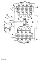
- Figure 10 shows a top view of a V-type gas-fueled engine equipped with the fuel supply device of this invention
- Figure 11 is an enlarged top sectional view of the principal parts from Figure 10
- Figure 12 is a view of Figure 10 sighted along arrow XII.
- Components which correspond or are equivalent to those explained for the foregoing Figures 1 through 9 bear the same reference numbers and detailed explanation of them will be omitted.
- the engine 1 shown in Figures 10 through 12 is a V-type engine formed from two cylinder banks 91, 92 composed of 4 cylinders each.
- An air intake manifold 20 is present for each of the cylinder banks that are located inside the V-bank.
- a throttle valve device 23 is connected upstream to the openings of these air intake manifolds 20 inside the V-bank 93.
- the air intake passage inside the air intake pipe 23a has been branched in two directions on the downstream side, in a manner such that it is T-shaped when viewed from above.
- Throttle valves 36 are installed in the downstream side of each of the branches of the air intake pipe. In this embodiment, the axes of the throttle valves are horizontal.
- the mixer 22 Further upstream of the air intake pipe 23a is the mixer 22. As is shown in Figure 10, it is located outside the V-bank 93 in the crankshaft direction. As shown in Figure 12, the throttle valves 36 located inside the V-bank 93 are positioned at roughly the same height as the mixer 22 which is located outside the V-bank.
- the fuel supply device of this invention when connected as shown to a V-type engine 1, the comparatively small sized throttle valves 36 are located inside the V-bank 93 of engine 1, while the comparatively large mixer 22 is located outside the V-bank, and such an arrangements does not add to the overall engine height requirements. Accordingly, when this V-type engine 1 is mounted in an automobile, the height of the hood need not be increased.
- LPG gas was used as the gaseous fuel in the foregoing embodiments, but equivalent effects may be obtained when using other gaseous fuels such as LNG gas (liquefied natural gas) or CNG gas (natural gas). However, when CNG gas is used, a fuel vaporizing device is not needed.
- the fuel supply device for a gas-fuelled engine employs a variable venturi mixture-forming device to mix the gaseous fuel with the air for supply to the engine, wherein this variable venturi mixture-forming device is composed of a variable venturi mixer and a throttle valve which is formed separately from this mixer, to assure an adequate distance to separate the throttle valve from the venturi unit on the side of the engine.
- This arrangement prevents contaminants such as oil mists that are blown back into the air intake passage from moving backward past the throttle valve located in close proximity to the engine, and further the backward flow of such contaminants from the venturi to the throttle valve is virtually completely prevented by the relatively high density air intake flow.
- This design inhibits the adhesion of carbon and other deposits from forming on the openings in the venturi and the main jet, thereby maintaining their initial properties for a long period of time.
- the fuel supply device for gas-fuelled engines related to another preferred embodiment further provides that the throttle valve be positioned downstream of a bend area in the air intake pipe member so that any heavy contaminants that have been blown back past the throttle valve into the air intake system will be prevented from moving further backward by their collision with the inner wall at the bend area.
- this design prevents even further the possibility of contaminants adhering to the main jet of the mixer or to the venturi unit.
- variable venturi mixture-forming device be connected to an air intake passage that opens inside the V-bank of the V-type engine, and that the throttle valves be located inside the V-bank, while the variable venturi mixer be located outside the V-bank in the axial crankshaft direction, thereby allowing the emplacement of the comparatively small throttle valves inside the V-bank, and of the comparatively large variable venturi mixer outside the V-bank.
- This arrangement prevents the air/fuel intake system from adding to engine height requirements, so that when mounting this V-type engine in an automobile, hood height need not be increased.
Landscapes
- Engineering & Computer Science (AREA)
- Chemical & Material Sciences (AREA)
- Combustion & Propulsion (AREA)
- Mechanical Engineering (AREA)
- General Engineering & Computer Science (AREA)
- Chemical Kinetics & Catalysis (AREA)
- General Chemical & Material Sciences (AREA)
- Oil, Petroleum & Natural Gas (AREA)
- Output Control And Ontrol Of Special Type Engine (AREA)
Applications Claiming Priority (2)
| Application Number | Priority Date | Filing Date | Title |
|---|---|---|---|
| JP6068172A JPH07253049A (ja) | 1994-03-14 | 1994-03-14 | 気体燃料エンジン用燃料供給装置 |
| JP68172/94 | 1994-03-14 |
Publications (2)
| Publication Number | Publication Date |
|---|---|
| EP0672824A1 true EP0672824A1 (de) | 1995-09-20 |
| EP0672824B1 EP0672824B1 (de) | 1997-09-17 |
Family
ID=13366095
Family Applications (1)
| Application Number | Title | Priority Date | Filing Date |
|---|---|---|---|
| EP95103688A Expired - Lifetime EP0672824B1 (de) | 1994-03-14 | 1995-03-14 | Mit flüssigem Gas betriebene Brennkraftmaschine |
Country Status (4)
| Country | Link |
|---|---|
| US (1) | US5755203A (de) |
| EP (1) | EP0672824B1 (de) |
| JP (1) | JPH07253049A (de) |
| DE (1) | DE69500708T2 (de) |
Cited By (3)
| Publication number | Priority date | Publication date | Assignee | Title |
|---|---|---|---|---|
| FR2794800A1 (fr) * | 1999-04-23 | 2000-12-15 | Daimler Chrysler Ag | Moteur a combustion interne suralimente, fonctionnant avec un combustible gazeux |
| EP2694793A1 (de) * | 2011-04-01 | 2014-02-12 | Hydrogen Energy Systems, LLC | Mischblock |
| EP3296556A4 (de) * | 2015-05-14 | 2018-08-08 | Yanmar Co., Ltd. | Biogasbefeuerter motor |
Families Citing this family (5)
| Publication number | Priority date | Publication date | Assignee | Title |
|---|---|---|---|---|
| US7607421B2 (en) * | 2006-04-20 | 2009-10-27 | Woodward Governor Company | Pulsation-dampening fuel trim strategy for air/fuel ratio control of propane-fueled, spark-ignited engines |
| JP5084625B2 (ja) * | 2008-06-11 | 2012-11-28 | 本田技研工業株式会社 | ガスエンジンの燃料供給装置 |
| US9091240B2 (en) * | 2013-01-24 | 2015-07-28 | Caterpillar Inc. | Compressed natural gas fuel mass control system |
| US9909534B2 (en) * | 2014-09-22 | 2018-03-06 | Ini Power Systems, Inc. | Carbureted engine having an adjustable fuel to air ratio |
| JP7436766B2 (ja) * | 2020-12-25 | 2024-02-22 | 株式会社クボタ | 吸気マニホルドおよびエンジン |
Citations (9)
| Publication number | Priority date | Publication date | Assignee | Title |
|---|---|---|---|---|
| US4168685A (en) * | 1975-03-14 | 1979-09-25 | Little Allan V | Fuel metering device for internal combustion engines and fuel systems incorporating such device |
| JPS5578146A (en) * | 1978-12-08 | 1980-06-12 | Automob Antipollut & Saf Res Center | Closed loop air/fuel ratio control device for lpg engine |
| DE3044744C1 (de) * | 1980-11-27 | 1982-03-18 | Daimler-Benz Ag, 7000 Stuttgart | Fluessiggasanlage fuer Brennkraftmaschinen |
| JPS57143153A (en) * | 1981-02-27 | 1982-09-04 | Suzuki Motor Co Ltd | Suction device of internal combustion engine |
| GB2096243A (en) * | 1981-04-07 | 1982-10-13 | Bosch Pierburg System Ohg | Carburettors for internal combustion engines |
| US4381753A (en) * | 1979-11-12 | 1983-05-03 | Honda Giken Kogyo Kabushiki Kaisha | Evaporative emission control device of an internal combustion engine for vehicle use |
| DE3205935A1 (de) * | 1982-02-19 | 1983-09-08 | Karl Hopt GmbH Elektrotechnische Fabrik, 7464 Schömberg | Sekundaerluft-zufuehrung |
| WO1994004813A1 (en) * | 1992-08-13 | 1994-03-03 | King Format Limited | Vapourizer apparatus |
| JPH06241125A (ja) * | 1992-06-24 | 1994-08-30 | Yamaha Motor Co Ltd | 気体燃料エンジン用混合気形成装置 |
Family Cites Families (75)
| Publication number | Priority date | Publication date | Assignee | Title |
|---|---|---|---|---|
| US1954968A (en) * | 1925-10-05 | 1934-04-17 | Climax Engineering Company | Automatic fuel proportioning device for gas engines |
| US2016695A (en) * | 1933-05-20 | 1935-10-08 | Continental Motors Corp | Engine |
| US2475086A (en) * | 1946-08-09 | 1949-07-05 | Ensign Carburetor Company | Control of feed pressure for internal-combustion engines |
| US3111120A (en) * | 1961-09-01 | 1963-11-19 | Chrysler Corp | Engine crankcase ventilation system |
| US3646924A (en) * | 1971-03-23 | 1972-03-07 | Int Materials Corp | Fuel system for gaseous fueled engines |
| GB1327513A (en) * | 1971-04-19 | 1973-08-22 | Mcjones R W | Controlling exhaust gas pollution |
| US4020813A (en) * | 1973-06-05 | 1977-05-03 | Nippon Soken, Inc. | Air-to-fuel ratio control means for carbureter |
| US3996909A (en) * | 1975-02-21 | 1976-12-14 | General Motors Corporation | Fuel shut-off valve assembly |
| US3996908A (en) * | 1975-02-21 | 1976-12-14 | General Motors Corporation | Fuel shut-off valve assembly |
| GB1554234A (en) * | 1975-07-08 | 1979-10-17 | Bosch Gmbh Robert | Fuel supply systems for internal combustion engines |
| DE2715588C3 (de) * | 1977-04-07 | 1980-12-11 | Robert Bosch Gmbh, 7000 Stuttgart | Kraftstoffversorgungsanlage für eine Brennkraftmaschine mit einer Einrichtung zur Zumessung einer Zusatzkraftstoffmenge |
| US4327689A (en) * | 1979-10-03 | 1982-05-04 | The Bendix Corporation | Combined warm-up enrichment, engine roughness and exhaust gas sensor control for EFI engine |
| US4263883A (en) * | 1979-11-21 | 1981-04-28 | Ingersoll-Rand Company | Engine combustion control system |
| US4285700A (en) * | 1979-12-27 | 1981-08-25 | Borg-Warner Corporation | Fuel enrichment apparatus and method for gaseous fuel mixers |
| US4347824A (en) * | 1980-06-26 | 1982-09-07 | I.C.E. Company, Inc. | LPG Fuel supply system |
| JPS5723101A (en) * | 1980-07-16 | 1982-02-06 | Toyota Motor Corp | Controlling method for memory for internal combustion engine |
| US4369751A (en) * | 1980-08-13 | 1983-01-25 | Ayres Technologies, Inc. | Liquefied propane carburetor modification system |
| US4413607A (en) * | 1980-08-13 | 1983-11-08 | Batchelor William H | Propane carburetion system |
| JPS5751935A (en) * | 1980-09-12 | 1982-03-27 | Nippon Denso Co Ltd | Air-to-fuel return controller |
| US4369749A (en) * | 1981-01-27 | 1983-01-25 | Aisan Kogyo Kabushiki Kaisha | Variable venturi carburetor |
| US4404947A (en) * | 1981-03-10 | 1983-09-20 | Swanson Wayne A | Vapor/air control system |
| US4359024A (en) * | 1981-03-12 | 1982-11-16 | Lootens Charles W | Engine attachment |
| US4364364A (en) * | 1981-07-23 | 1982-12-21 | Cooper Industries, Inc. | Air-fuel ratio controller |
| DE3149136A1 (de) * | 1981-12-11 | 1983-06-23 | Robert Bosch Gmbh, 7000 Stuttgart | Einrichtung zur regelung des kraftstoff-luftverhaeltnisses bei brennkraftmaschinen |
| JPS58104351A (ja) * | 1981-12-15 | 1983-06-21 | Toyota Motor Corp | 可変ベンチユリ気化器の燃料制御装置 |
| JPS58140455A (ja) * | 1982-02-16 | 1983-08-20 | Toyota Motor Corp | 可変ベンチユリ型気化器 |
| DE3207787A1 (de) * | 1982-03-04 | 1983-09-08 | Robert Bosch Gmbh, 7000 Stuttgart | Kraftstoffzumesssystem fuer eine brennkraftmaschine |
| US4541397A (en) * | 1982-04-23 | 1985-09-17 | Emco Wheaton (International) Limited | Gaseous fuel carburetion system |
| JPS58192963A (ja) * | 1982-05-01 | 1983-11-10 | Sanshin Ind Co Ltd | 内燃機関の燃料制御装置 |
| JPS58217747A (ja) * | 1982-06-09 | 1983-12-17 | Honda Motor Co Ltd | 内燃エンジンの空燃比制御方法 |
| US4517134A (en) * | 1982-12-27 | 1985-05-14 | Nissan Motor Company, Ltd. | Variable venturi carburetor |
| US4699630A (en) * | 1983-01-14 | 1987-10-13 | Lpf Carburetion, Inc. | Fuel valve for air-vapor mixer |
| JPH0629590B2 (ja) * | 1983-03-25 | 1994-04-20 | トヨタ自動車株式会社 | 内燃機関の空燃比制御方法 |
| JPS59201946A (ja) * | 1983-04-28 | 1984-11-15 | Honda Motor Co Ltd | 内燃エンジンの空燃比制御装置 |
| DE3319432A1 (de) * | 1983-05-28 | 1984-11-29 | Robert Bosch Gmbh, 7000 Stuttgart | Verfahren und einrichtung zur regelung des betriebsgemisches einer brennkraftmaschine |
| DE3321424A1 (de) * | 1983-06-14 | 1984-08-16 | Robert Bosch Gmbh, 7000 Stuttgart | Regeleinrichtung fuer die gemischzusammensetzung einer mit gasfoermigem kraftstoff betriebenen brennkraftmaschine |
| DE3327699A1 (de) * | 1983-08-01 | 1985-02-21 | Motoren-Werke Mannheim AG vorm. Benz Abt. stationärer Motorenbau, 6800 Mannheim | Einrichtung zur anpassung an gase unterschiedlicher heizwerte bei der gas-luft-gemisch-versorgung von gasmotoren |
| JPS6032031A (ja) * | 1983-08-03 | 1985-02-19 | Canon Inc | 撮影装置 |
| JPS60219429A (ja) * | 1984-04-16 | 1985-11-02 | Fuji Heavy Ind Ltd | 空燃比制御装置 |
| US4606319A (en) * | 1984-08-20 | 1986-08-19 | Silva Robert E | System and method of vaporizing liquid fuel for delivery to an internal combustion engine |
| JPS61192826A (ja) * | 1985-02-20 | 1986-08-27 | Toyota Motor Corp | 内燃機関の燃料カツト復帰時の燃料供給制御方法 |
| US4638783A (en) * | 1985-04-12 | 1987-01-27 | Dresser Industries, Inc. | Carburetion system for engines |
| US4686951A (en) * | 1985-06-24 | 1987-08-18 | Dresser Industries, Inc. | Method and apparatus for carburetion |
| DE3541484A1 (de) * | 1985-11-15 | 1987-11-19 | Erich A Dolderer | Innere gemischbildung |
| JPS62131908A (ja) * | 1985-12-03 | 1987-06-15 | Honda Motor Co Ltd | 2サイクル機関用潤滑油ポンプの制御装置 |
| DE3612994A1 (de) * | 1986-04-17 | 1987-10-29 | Hi Tec Gas International Gmbh | Dosiervorrichtung fuer gasfoermigen kraftstoff |
| US4813394A (en) * | 1986-06-03 | 1989-03-21 | St Clair Christie C | Carburetion systems |
| CA1282655C (en) * | 1986-06-27 | 1991-04-09 | Horst Bergmann | Regulation for a gas engine |
| DE3637304A1 (de) * | 1986-08-23 | 1988-05-05 | Vdo Schindling | Verfahren und schaltungsanordnung zur erkennung der betriebsbereitschaft einer sauerstoffmesssonde |
| JPS63212742A (ja) * | 1987-02-27 | 1988-09-05 | Fuji Heavy Ind Ltd | 内燃機関の燃料制御装置 |
| JP2535897B2 (ja) * | 1987-04-06 | 1996-09-18 | トヨタ自動車株式会社 | 内燃機関の空燃比制御装置 |
| US4938199A (en) * | 1987-08-31 | 1990-07-03 | Honda Giken Kogyo Kabushiki Kaisha | Method for controlling the air-fuel ratio in vehicle internal combustion engines |
| JPH0823286B2 (ja) * | 1987-10-01 | 1996-03-06 | 本田技研工業株式会社 | 2サイクルエンジンの潤滑装置 |
| US4864991A (en) * | 1987-12-01 | 1989-09-12 | Snyder Warren E | Method and apparatus for controlling air to gas ratio of gaseous fueled engines |
| JP2630372B2 (ja) * | 1988-03-18 | 1997-07-16 | 本田技研工業株式会社 | 内燃エンジンの排気成分濃度検出器の活性化判別方法 |
| US4970858A (en) * | 1988-03-30 | 1990-11-20 | Toyota Jidosha Kabushiki Kaisha | Air-fuel ratio feedback system having improved activation determination for air-fuel ratio sensor |
| US4813390A (en) * | 1988-04-04 | 1989-03-21 | Bennett David E | Air gas mixing device with valve position detector |
| NL8801554A (nl) * | 1988-06-17 | 1990-01-16 | Necam Bv | Intelligente besturing van autogasapparatuur. |
| US4829957A (en) * | 1988-07-11 | 1989-05-16 | Garretson Equipment Co., Inc. | Gaseous fuel injection system for internal combustion engines |
| JP2850130B2 (ja) * | 1988-10-20 | 1999-01-27 | ヤマハ発動機株式会社 | 2サイクルエンジンの潤滑装置 |
| JPH02139307A (ja) * | 1988-11-18 | 1990-05-29 | Kawakami Shoji Kk | 包装装置 |
| CA1326794C (en) * | 1989-09-29 | 1994-02-08 | Ortech Corporation | Flow control system |
| DE3940752A1 (de) * | 1989-12-09 | 1991-06-13 | Bosch Gmbh Robert | Verfahren zum steuern eines ottomotors ohne drosselklappe |
| JP2745754B2 (ja) * | 1990-01-23 | 1998-04-28 | トヨタ自動車株式会社 | 酸素センサの活性判定装置 |
| JP2784549B2 (ja) * | 1990-02-27 | 1998-08-06 | ヤンマーディーゼル株式会社 | 希薄燃焼式ガス機関 |
| JPH041456A (ja) * | 1990-04-13 | 1992-01-06 | Sanshin Ind Co Ltd | 船舶推進機の燃料供給装置 |
| US5101799A (en) * | 1990-04-20 | 1992-04-07 | Vr Systems, Inc. | Mixture control unit for use with the control system of a soil venting apparatus |
| US5076245A (en) * | 1990-08-01 | 1991-12-31 | David P. Ward | Fuel pressure control system for gaseous fuel engines |
| JPH07107379B2 (ja) * | 1990-09-10 | 1995-11-15 | 東京瓦斯株式会社 | ガスエンジンの空燃比制御方法 |
| JP2748686B2 (ja) * | 1990-11-16 | 1998-05-13 | トヨタ自動車株式会社 | 筒内直接噴射式火花点火機関 |
| JP2905304B2 (ja) * | 1991-04-02 | 1999-06-14 | 三菱電機株式会社 | 空燃比センサの活性化判定装置 |
| US5251602A (en) * | 1991-04-20 | 1993-10-12 | Yamaha Hatsudoki Kabushiki Kaisha | Fuel supply system for gas-fueled engine |
| JPH05164002A (ja) * | 1991-12-16 | 1993-06-29 | Matsuda Sangyo Kk | 定置式ガスエンジンの燃料制御装置 |
| US5293741A (en) * | 1992-01-31 | 1994-03-15 | Mazda Motor Corporation | Warming-up system for warming up an engine for an automotive vehicle |
| US5357935A (en) * | 1993-06-22 | 1994-10-25 | Clark Material Handling Company | Internal combustion engine with induction fuel system having an engine shut down circuit |
-
1994
- 1994-03-14 JP JP6068172A patent/JPH07253049A/ja active Pending
-
1995
- 1995-03-09 US US08/401,348 patent/US5755203A/en not_active Expired - Fee Related
- 1995-03-14 EP EP95103688A patent/EP0672824B1/de not_active Expired - Lifetime
- 1995-03-14 DE DE69500708T patent/DE69500708T2/de not_active Expired - Fee Related
Patent Citations (9)
| Publication number | Priority date | Publication date | Assignee | Title |
|---|---|---|---|---|
| US4168685A (en) * | 1975-03-14 | 1979-09-25 | Little Allan V | Fuel metering device for internal combustion engines and fuel systems incorporating such device |
| JPS5578146A (en) * | 1978-12-08 | 1980-06-12 | Automob Antipollut & Saf Res Center | Closed loop air/fuel ratio control device for lpg engine |
| US4381753A (en) * | 1979-11-12 | 1983-05-03 | Honda Giken Kogyo Kabushiki Kaisha | Evaporative emission control device of an internal combustion engine for vehicle use |
| DE3044744C1 (de) * | 1980-11-27 | 1982-03-18 | Daimler-Benz Ag, 7000 Stuttgart | Fluessiggasanlage fuer Brennkraftmaschinen |
| JPS57143153A (en) * | 1981-02-27 | 1982-09-04 | Suzuki Motor Co Ltd | Suction device of internal combustion engine |
| GB2096243A (en) * | 1981-04-07 | 1982-10-13 | Bosch Pierburg System Ohg | Carburettors for internal combustion engines |
| DE3205935A1 (de) * | 1982-02-19 | 1983-09-08 | Karl Hopt GmbH Elektrotechnische Fabrik, 7464 Schömberg | Sekundaerluft-zufuehrung |
| JPH06241125A (ja) * | 1992-06-24 | 1994-08-30 | Yamaha Motor Co Ltd | 気体燃料エンジン用混合気形成装置 |
| WO1994004813A1 (en) * | 1992-08-13 | 1994-03-03 | King Format Limited | Vapourizer apparatus |
Non-Patent Citations (3)
| Title |
|---|
| PATENT ABSTRACTS OF JAPAN vol. 004, no. 120 (M - 028) 26 August 1980 (1980-08-26) * |
| PATENT ABSTRACTS OF JAPAN vol. 006, no. 246 (M - 176) 4 December 1982 (1982-12-04) * |
| PATENT ABSTRACTS OF JAPAN vol. 018, no. 628 (M - 1713) 30 November 1994 (1994-11-30) * |
Cited By (4)
| Publication number | Priority date | Publication date | Assignee | Title |
|---|---|---|---|---|
| FR2794800A1 (fr) * | 1999-04-23 | 2000-12-15 | Daimler Chrysler Ag | Moteur a combustion interne suralimente, fonctionnant avec un combustible gazeux |
| EP2694793A1 (de) * | 2011-04-01 | 2014-02-12 | Hydrogen Energy Systems, LLC | Mischblock |
| EP2694793A4 (de) * | 2011-04-01 | 2014-09-10 | Hydrogen Energy Systems Llc | Mischblock |
| EP3296556A4 (de) * | 2015-05-14 | 2018-08-08 | Yanmar Co., Ltd. | Biogasbefeuerter motor |
Also Published As
| Publication number | Publication date |
|---|---|
| EP0672824B1 (de) | 1997-09-17 |
| DE69500708D1 (de) | 1997-10-23 |
| JPH07253049A (ja) | 1995-10-03 |
| DE69500708T2 (de) | 1998-01-08 |
| US5755203A (en) | 1998-05-26 |
Similar Documents
| Publication | Publication Date | Title |
|---|---|---|
| EP1103716B1 (de) | Lufteinlassanordnung für Brennkraftmaschine | |
| EP0736684B1 (de) | Einlasskrümmer für Brennkraftmaschine | |
| US5529048A (en) | Fuel control and feed system for gas fueled engine | |
| US4114566A (en) | Hot fuel gas generator | |
| EP1878892A2 (de) | Mehrzylinder-Ottomotor | |
| US5474053A (en) | Control for gaseous fueled engine | |
| US5251602A (en) | Fuel supply system for gas-fueled engine | |
| EP0745767A2 (de) | Mehrzylinder-, Brennstoffeinspritzbrennkraftmaschine und Brennstoffeinspritzverfahren | |
| EP0672824B1 (de) | Mit flüssigem Gas betriebene Brennkraftmaschine | |
| US5331937A (en) | Charge inlet system for internal combustion engine | |
| US6843236B1 (en) | Multi-phase fuel system | |
| WO1993000509A1 (en) | Fuel inlet system for internal combustion engine | |
| US4348338A (en) | Injection-type pressure-freed carburetor | |
| US5827335A (en) | Enhanced performance carburetor system | |
| US4470391A (en) | Air-fuel mixture intake construction for internal combustion engines | |
| EP0060656A1 (de) | Zumessvorrichtung für gasförmigen Brennstoff und Luft für Brennkraftmaschine | |
| US6843238B2 (en) | Cold start fuel control system | |
| US5546919A (en) | Operating arrangement for gaseous fueled engine | |
| US5678527A (en) | Induction and charge forming system for gaseous fueled engine | |
| US3996907A (en) | Fuel induction system | |
| JP3265060B2 (ja) | 気体燃料エンジン用混合気形成装置 | |
| US3971352A (en) | Fuel induction system | |
| EP0953761B1 (de) | Brennkraftmaschine mit Hilfseinlasskanal | |
| US4430982A (en) | Carburetor for an internal combustion engine | |
| US5320081A (en) | Fuel injection economizer |
Legal Events
| Date | Code | Title | Description |
|---|---|---|---|
| PUAI | Public reference made under article 153(3) epc to a published international application that has entered the european phase |
Free format text: ORIGINAL CODE: 0009012 |
|
| AK | Designated contracting states |
Kind code of ref document: A1 Designated state(s): DE FR GB |
|
| 17P | Request for examination filed |
Effective date: 19960319 |
|
| 17Q | First examination report despatched |
Effective date: 19960502 |
|
| GRAG | Despatch of communication of intention to grant |
Free format text: ORIGINAL CODE: EPIDOS AGRA |
|
| GRAH | Despatch of communication of intention to grant a patent |
Free format text: ORIGINAL CODE: EPIDOS IGRA |
|
| GRAH | Despatch of communication of intention to grant a patent |
Free format text: ORIGINAL CODE: EPIDOS IGRA |
|
| GRAA | (expected) grant |
Free format text: ORIGINAL CODE: 0009210 |
|
| AK | Designated contracting states |
Kind code of ref document: B1 Designated state(s): DE FR GB |
|
| REF | Corresponds to: |
Ref document number: 69500708 Country of ref document: DE Date of ref document: 19971023 |
|
| ET | Fr: translation filed | ||
| PLBE | No opposition filed within time limit |
Free format text: ORIGINAL CODE: 0009261 |
|
| STAA | Information on the status of an ep patent application or granted ep patent |
Free format text: STATUS: NO OPPOSITION FILED WITHIN TIME LIMIT |
|
| 26N | No opposition filed | ||
| REG | Reference to a national code |
Ref country code: GB Ref legal event code: IF02 |
|
| PGFP | Annual fee paid to national office [announced via postgrant information from national office to epo] |
Ref country code: FR Payment date: 20040309 Year of fee payment: 10 |
|
| PGFP | Annual fee paid to national office [announced via postgrant information from national office to epo] |
Ref country code: GB Payment date: 20040310 Year of fee payment: 10 |
|
| PG25 | Lapsed in a contracting state [announced via postgrant information from national office to epo] |
Ref country code: GB Free format text: LAPSE BECAUSE OF NON-PAYMENT OF DUE FEES Effective date: 20050314 |
|
| GBPC | Gb: european patent ceased through non-payment of renewal fee |
Effective date: 20050314 |
|
| PG25 | Lapsed in a contracting state [announced via postgrant information from national office to epo] |
Ref country code: FR Free format text: LAPSE BECAUSE OF NON-PAYMENT OF DUE FEES Effective date: 20051130 |
|
| REG | Reference to a national code |
Ref country code: FR Ref legal event code: ST Effective date: 20051130 |
|
| PGFP | Annual fee paid to national office [announced via postgrant information from national office to epo] |
Ref country code: DE Payment date: 20060309 Year of fee payment: 12 |
|
| PG25 | Lapsed in a contracting state [announced via postgrant information from national office to epo] |
Ref country code: DE Free format text: LAPSE BECAUSE OF NON-PAYMENT OF DUE FEES Effective date: 20071002 |